EP2853886B1 - Magnetic measurement method and system - Google Patents
Magnetic measurement method and system Download PDFInfo
- Publication number
- EP2853886B1 EP2853886B1 EP14186380.3A EP14186380A EP2853886B1 EP 2853886 B1 EP2853886 B1 EP 2853886B1 EP 14186380 A EP14186380 A EP 14186380A EP 2853886 B1 EP2853886 B1 EP 2853886B1
- Authority
- EP
- European Patent Office
- Prior art keywords
- sample
- ray
- magnetic
- rays
- magnetic field
- Prior art date
- Legal status (The legal status is an assumption and is not a legal conclusion. Google has not performed a legal analysis and makes no representation as to the accuracy of the status listed.)
- Active
Links
- 230000005291 magnetic effect Effects 0.000 title claims description 83
- 238000000691 measurement method Methods 0.000 title claims description 6
- 230000010287 polarization Effects 0.000 claims description 21
- 238000005259 measurement Methods 0.000 claims description 18
- 230000005540 biological transmission Effects 0.000 claims description 16
- 238000010884 ion-beam technique Methods 0.000 claims description 12
- 230000009102 absorption Effects 0.000 claims description 9
- 238000010521 absorption reaction Methods 0.000 claims description 9
- 238000002983 circular dichroism Methods 0.000 claims description 9
- 230000005855 radiation Effects 0.000 claims description 6
- 238000005530 etching Methods 0.000 claims description 5
- 230000004907 flux Effects 0.000 claims description 3
- 230000001678 irradiating effect Effects 0.000 claims description 2
- 239000000523 sample Substances 0.000 description 61
- 238000000034 method Methods 0.000 description 17
- 238000002834 transmittance Methods 0.000 description 10
- 238000007796 conventional method Methods 0.000 description 6
- 238000003384 imaging method Methods 0.000 description 5
- 230000005381 magnetic domain Effects 0.000 description 5
- 238000001514 detection method Methods 0.000 description 4
- 238000009826 distribution Methods 0.000 description 4
- 239000000696 magnetic material Substances 0.000 description 4
- 229910001172 neodymium magnet Inorganic materials 0.000 description 4
- 239000013078 crystal Substances 0.000 description 3
- 239000000463 material Substances 0.000 description 3
- 239000011859 microparticle Substances 0.000 description 3
- 239000002245 particle Substances 0.000 description 3
- 238000002360 preparation method Methods 0.000 description 3
- 230000035945 sensitivity Effects 0.000 description 3
- 230000007717 exclusion Effects 0.000 description 2
- 230000005415 magnetization Effects 0.000 description 2
- 239000013081 microcrystal Substances 0.000 description 2
- 239000000126 substance Substances 0.000 description 2
- 230000005374 Kerr effect Effects 0.000 description 1
- 238000003917 TEM image Methods 0.000 description 1
- 238000000862 absorption spectrum Methods 0.000 description 1
- 239000003086 colorant Substances 0.000 description 1
- 239000000470 constituent Substances 0.000 description 1
- 238000011161 development Methods 0.000 description 1
- 230000000694 effects Effects 0.000 description 1
- 238000010894 electron beam technology Methods 0.000 description 1
- 238000000921 elemental analysis Methods 0.000 description 1
- 230000005284 excitation Effects 0.000 description 1
- 230000005389 magnetism Effects 0.000 description 1
- 239000004570 mortar (masonry) Substances 0.000 description 1
- 239000013307 optical fiber Substances 0.000 description 1
- 238000012545 processing Methods 0.000 description 1
- 238000012552 review Methods 0.000 description 1
- 238000001040 scanning transmission X-ray microscopy Methods 0.000 description 1
- 238000010183 spectrum analysis Methods 0.000 description 1
- 238000012916 structural analysis Methods 0.000 description 1
- 230000005469 synchrotron radiation Effects 0.000 description 1
Images
Classifications
-
- G—PHYSICS
- G01—MEASURING; TESTING
- G01N—INVESTIGATING OR ANALYSING MATERIALS BY DETERMINING THEIR CHEMICAL OR PHYSICAL PROPERTIES
- G01N23/00—Investigating or analysing materials by the use of wave or particle radiation, e.g. X-rays or neutrons, not covered by groups G01N3/00 – G01N17/00, G01N21/00 or G01N22/00
- G01N23/02—Investigating or analysing materials by the use of wave or particle radiation, e.g. X-rays or neutrons, not covered by groups G01N3/00 – G01N17/00, G01N21/00 or G01N22/00 by transmitting the radiation through the material
- G01N23/06—Investigating or analysing materials by the use of wave or particle radiation, e.g. X-rays or neutrons, not covered by groups G01N3/00 – G01N17/00, G01N21/00 or G01N22/00 by transmitting the radiation through the material and measuring the absorption
- G01N23/083—Investigating or analysing materials by the use of wave or particle radiation, e.g. X-rays or neutrons, not covered by groups G01N3/00 – G01N17/00, G01N21/00 or G01N22/00 by transmitting the radiation through the material and measuring the absorption the radiation being X-rays
- G01N23/085—X-ray absorption fine structure [XAFS], e.g. extended XAFS [EXAFS]
-
- G—PHYSICS
- G01—MEASURING; TESTING
- G01N—INVESTIGATING OR ANALYSING MATERIALS BY DETERMINING THEIR CHEMICAL OR PHYSICAL PROPERTIES
- G01N23/00—Investigating or analysing materials by the use of wave or particle radiation, e.g. X-rays or neutrons, not covered by groups G01N3/00 – G01N17/00, G01N21/00 or G01N22/00
- G01N23/02—Investigating or analysing materials by the use of wave or particle radiation, e.g. X-rays or neutrons, not covered by groups G01N3/00 – G01N17/00, G01N21/00 or G01N22/00 by transmitting the radiation through the material
- G01N23/04—Investigating or analysing materials by the use of wave or particle radiation, e.g. X-rays or neutrons, not covered by groups G01N3/00 – G01N17/00, G01N21/00 or G01N22/00 by transmitting the radiation through the material and forming images of the material
-
- G—PHYSICS
- G01—MEASURING; TESTING
- G01N—INVESTIGATING OR ANALYSING MATERIALS BY DETERMINING THEIR CHEMICAL OR PHYSICAL PROPERTIES
- G01N27/00—Investigating or analysing materials by the use of electric, electrochemical, or magnetic means
- G01N27/72—Investigating or analysing materials by the use of electric, electrochemical, or magnetic means by investigating magnetic variables
-
- G—PHYSICS
- G01—MEASURING; TESTING
- G01N—INVESTIGATING OR ANALYSING MATERIALS BY DETERMINING THEIR CHEMICAL OR PHYSICAL PROPERTIES
- G01N2223/00—Investigating materials by wave or particle radiation
- G01N2223/40—Imaging
- G01N2223/405—Imaging mapping of a material property
Definitions
- the present invention relates to a magnetic measurement method and system.
- the Paper 1 has reported the original X-ray magnetic circular dichroism as follows: a magnetic sample is placed in the external strong magnetic field, an internal magnetization direction of the magnetic sample is aligned with one direction, then the sample is irradiated with circular polarization X-ray while the external magnetic field direction is alternately inverted, resultantly, intensity of transmission X-ray passing the sample is changed in accordance with whether the external magnetic field direction is parallel or anti-parallel to the polarization light direction, the intensity change appears remarkably at a neighborhood of X-ray absorption edge for the constituent element of the magnetic sample.
- a very old method such as disclosed in the patent literature 1 has been presented to observe magnetic samples.
- the conventional method presents several difficult problems: (1) the conventional method is merely able to observe magnetic characteristics in the region from uppermost surfaces of the sample to several nanometers in depth but unable to observe them over several nanometers in depth because any electrons to generate from places deeper than several nanometers cannot get out of the sample surfaces.
- the method is the one to detect the secondary electrons that are emitted from the magnetic sample on absorption of synchrotron radiation light
- the conventional method has the essentially undesirable problem that the observed analytical result does not always show true magnetic properties of the bulk due to interruption effect of oxidized layers in the uppermost surfaces
- the conventional method is undesirable to observe the magnetic sample within magnetic field because of an applied magnetic field to exert influence on the detection of the secondary electrons. For these reasons, it has been very difficult to accurately measure the magnetized structure in the inside of micro-particles.
- Element-Specific Magnetic Domain Imaging is known from KANTA ONO ET AL: "Element-specific magnetic domain imaging of (Nd, Dy)-Fe-B sintered magnets using scanning transmission X-ray microscopy", IEEE Transactions on Magnetics, vol. 47, Oct. 2011, pages 2672 - 2675 .
- the method uses circularly polarized X-rays for magnetic imaging, a Fresnel zone plate to focus X-rays, an order-sorting aperture to block zero-order light and samples rastered with respect to the focused soft X-ray beam.
- the magnetic characteristic of magnetic body is almost determined by the magnetic properties in the micro-region. Therefore, it is necessary for the development of new magnetic materials to assign magnetic properties of the micro-particles.
- the conventional methods such as disclosed in the above patent literature 1, Kerr effect microscope, magnetic force microscope, photo-electron microscope and the like, which have been known to obtain the magnetic information such as magnetic domain and magnetic moment, make it possible to observe the magnetic properties in the uppermost sample surfaces or averaged magnetic properties of polycrystalline materials.
- the conventional methods have been unable to observe even the magnetic properties of a single micro-particle as explained above.
- the object of the present invention is, in view of the above described circumstances, to provide a method, a system and an apparatus that are capable of measuring true magnetic characteristic of crystal grains composing magnetic polycrystalline materials.
- the invention refers to a magnetic measurement method according to claim 1 and a magnetic measurement system according to claim 3.
- the present invention provides a method and a system that are capable of measuring the magnetic characteristic of sample within external magnetic field by X-ray magnetic circular dichroism.
- the present invention provides a method and a system to measure accurately and directly magnetic characteristic of very thick samples of 1 ⁇ m.
- the present invention is able to directly measure transmittance of transmission X-ray passing the sample placed within external magnetic field, using the Avalanche photodiode to measure photo-count of X-ray magnetic circular dichroism. Therefore, the present invention makes it possible to carry out high sensitive and high precise measurement of magnetic sensitivity, magnetic state and magnetic structure of the bulk sample. Accordingly, the present invention makes it possible to measure the magnetic characteristic of single crystal grains in the sample of 50 nm ⁇ 1000 nm in thickness.
- the sample to be measured is cut into a microtome section of 50 nm in thickness.
- Preferable thickness of microtome section can be determined mainly by sample material, kinetic energy of used X-ray and transmittance of X-ray.
- a use of X-ray transmittance of 1 % or more is sufficient for the measurement of micro-crystal grains.
- the thickness of microtome section is preferably 1000 nm or less, more preferably 50 nm ⁇ 100 nm.
- the preparation of the microtome section of 50 nm ⁇ 100 nm in thickness makes it possible to measure magnetic characteristic of micro-crystal grains and imaging with resolution of 100 nm or less, and accordingly makes it possible to study local magnetic sensitivity induced by an applied magnetic field.
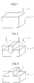
- microtome section For the preparation of microtome section, various methods can be used. For the preparation of microtome section of 1000 nm or less, the etching using focused ion beams is preferable. For example, the sample 1 as shown in Fig. 1 is etched using the focused ion beam 2, followed by obtaining a microtome section 1000 nm or less thick as shown in Fig. 2 .
- various materials for example, soft magnetic materials, hard magnetic materials, magnetic materials with plural magnetic phases, can be applied.
- a usual focused ion beam machine comprising an ion beam gun and optic system to generate Ga-ion beams and scanning system to scan ion beams on the sample surfaces can be utilized.
- an observation place is irradiated with the X-ray 3, followed by detection the transmission X-ray to measure magnetic characteristic of the sample.
- X-ray to be applied to the sample is circular polarization X-ray focused into 10 nm in beam size.
- the X-ray 3 generated by an X-ray generator which is capable of generating right-circular polarization X-ray and left-circular polarization X-ray enters a measurement place of the sample 1, successively the transmission X-ray is detected by a detector.
- the intensity IR of the transmission X-ray corresponding to right-circular polarization X-ray and the intensity IL of the transmission X-ray corresponding to left-circular polarization X-ray are alternately measured, successively the difference between them, that is, XMCD, can be detected.
- This measurement corresponds to the magnetization in the inside of the X-ray incident position. Successively, the same measurement is carried out while two-dimensional (2-D)-scanning the sample, thus a 2-D-data is obtained.
- the X-ray absorption parallel to the magnetic field direction of the sample and that in the anti-parallel direction are measured using either right-circular polarization X-ray or left-circular polarization X-ray, the difference between them, that is, XMCD, can be also measured.
- the method has the element-selectivity, that is, the method is capable of measuring the direction of magnetic moment for a specific element by adjusting X-ray energy with an excitation energy gap between specific electron orbital.
- an absorption spectrum changes in accordance with the direction of angular momentum of circular polarization light and the direction of angular momentum of atom.
- the basic magnetic properties such as orbital angular momentum, spin angular momentum and magnetic momentum can be measured from (1) the measurement of angular momentum of circular polarization X-ray and that of atom in the case both momentums are parallel; (2) the measurement of angular momentum of circular polarization X-ray and that of atom in the case both momentums are anti-paralle; (3) the difference between them, that is, XMCD.
- the present measurement system comprises a radiation source, a monochromator to disperse white radiation into monochromatic X-ray, an aperture slit to enter X-ray of the radiation source into an analytical section, the analytical section equipping a combination of Fresnel zone plate and order-sorting aperture to focus X-ray flux passing the aperture slit, a sample-stage to set a sample to be irradiated with X-ray and an X-ray-detector to detect transmission X-ray passing the sample; which is characterized by the measurement of X-ray magnetic circular dichroism of X-ray passing the sample within magnet field or nonmagnetic field.
- the XMCD at each sample place can be measured through precisely scanning the sample stage and using focused radiation light.
- the present measurement apparatus comprises the aperture slit, the analytical section equipping a combination of Fresnel zone plate (FZP) and order-sorting aperture (OSA) to focus X-ray flux passing the aperture slit, the sample-stage to set a sample to be irradiated with X-ray and the X-ray-detector equipping the Avalanche photodiode to detect transmittance of transmission X-ray passing the sample.
- the FZP, OSA, sample-stage and X-ray-detector are equipping piezoelectric devices, therefore their X-, Y- and Z-stages can be controlled to an accuracy of nanometers.
- the Avalanche photodiode having dynamic ranges and optical fibers which is used within external magnetic field is preferable.
- the exclusion of heat-generating parts such as mortars and laser prevents the resolution of APD from thermal drift. Therefore, such exclusion is necessary to measure XMCD of a single particle in the nano-crystalline magnet.
- a combination system of superconductive magnet and use of non-magnetic parts and devices is preferable.
- a bulk sample of Nd 2 Fe 14 B or Sm 2 Fe 17 N 3 is used as the sample.
- the sample is fabricated using focused ion beams, followed by measuring X-ray transmittance at each sample position.
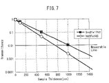
- the measurement of X-ray transmittance for the Nd 2 Fe 14 B sample or Sm 2 Fe 17 N 3 sample is based on the Nd-absorption-edge X-ray energy (980.4 eV) or Sm-absorption-edge X-ray energy (1083.3 eV), respectively. The result is shown in Fig. 7 .
- the Nd 2 Fe 14 B sample is measurable in the range 750 nm or less, 500 nm or less, 100 nm or less in thickness and that the Sm 2 Fe 17 N 3 sample is measurable in the range 1000 nm or less, 500 nm or less, 100 nm or less in thickness.
- a bulk sample of Nd-Fe-B magnet is used for the sample.
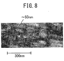
- a TEM image ( Fig. 8 ) of lateral face of the sample is observed. From Fig. 8 , the observed crystalline particle is estimated to be about 50 nm ⁇ 100 nm in size.
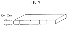
- the fabricated sample as shown in Fig. 9 is etched using focused ion beam.
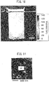
- X-ray transmittance of the obtained sample is measured, followed by determining thickness distribution as shown in Fig 10 .
- the sample is found to be fabricated into 50 nm in thickness.
- Fig. 11 shows a XMCD space distribution.
- the difference in contrasting density of white and black colors shows the difference for the direction of magnetic moment corresponding to the magnetic domain phase of magnetic body.
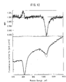
- the magnetic characteristic at the part (A) in Fig. 11 is found to have two peaks at 981 eV and 1003 eV, respectively, as shown in Fig. 12 . From the spectrum analysis, it is found that the magnetism property such as spin magnetic momentum and orbital magnetic momentum can be measured for a single crystal particle.
Description
- This application is based on and claims the benefit of priority Japanese Patent Application No.
JP2013-198163, filed on Sep. 25, 2013 - The present invention relates to a magnetic measurement method and system.
- The
Paper 1 has reported the original X-ray magnetic circular dichroism as follows: a magnetic sample is placed in the external strong magnetic field, an internal magnetization direction of the magnetic sample is aligned with one direction, then the sample is irradiated with circular polarization X-ray while the external magnetic field direction is alternately inverted, resultantly, intensity of transmission X-ray passing the sample is changed in accordance with whether the external magnetic field direction is parallel or anti-parallel to the polarization light direction, the intensity change appears remarkably at a neighborhood of X-ray absorption edge for the constituent element of the magnetic sample. Applying the above X-ray magnetic circular dichroism, a very old method such as disclosed in thepatent literature 1 has been presented to observe magnetic samples. Thepatent literature 1 presented the method and apparatus to observe magnetic domain by X-ray magnetic circular dichroism (XMCD) as follows: the intensity (I0) of incident X-ray and intensity (It) of transmission X-ray passing the sample are measured, µR×t = ln(I0/It) and µL×t = ln(I0/It) are calculated using the observed intensity (I0) and observed intensity (It), M= (µR×t-µL×t)/(µR×t+µL×t)= (µR-µL)(µR+µL) is calculated using [µR×t] and [µL×t], and M is transformed into electronic signal for imaging, here, µR and µL are X-ray absorption coefficient for right-circular polarization X-ray and left-circular polarization X-ray, respectively, and t is thickness of the sample. However the method was impracticable because focusing of X-ray is not good, sensitivity of X-ray detection is very low, and X-ray transmittance for right-circular polarization X-ray and left-circular polarization X-ray are calculated from observed X-ray intensity ln(I0/It) but indirectly observed. - Observation, structural analysis and elemental analysis of the structures and chemical and physical states of magnetic sample surfaces or their neighborhood have been studied using the secondary electrons which are emitted from the sample surfaces by irradiating the observed areas of the sample with electron beams or exciting light. For example, the
patent literature 2 presented the method to form observation images of microscopic structures of the sample. However, the above conventional method presents several difficult problems: (1) the conventional method is merely able to observe magnetic characteristics in the region from uppermost surfaces of the sample to several nanometers in depth but unable to observe them over several nanometers in depth because any electrons to generate from places deeper than several nanometers cannot get out of the sample surfaces. Because, the method is the one to detect the secondary electrons that are emitted from the magnetic sample on absorption of synchrotron radiation light, (2) the conventional method has the essentially undesirable problem that the observed analytical result does not always show true magnetic properties of the bulk due to interruption effect of oxidized layers in the uppermost surfaces, (3) the conventional method is undesirable to observe the magnetic sample within magnetic field because of an applied magnetic field to exert influence on the detection of the secondary electrons. For these reasons, it has been very difficult to accurately measure the magnetized structure in the inside of micro-particles. -
- [Paper 1] Physical Review Letters, vol. 58, pp.737-740 (1987)
- [Patent Literature 1]
JP-A-1993-045304 - [Patent Literature 2]
JP-A-2010-151455 - Moreover, a method of Element-Specific Magnetic Domain Imaging is known from KANTA ONO ET AL: "Element-specific magnetic domain imaging of (Nd, Dy)-Fe-B sintered magnets using scanning transmission X-ray microscopy", IEEE Transactions on Magnetics, vol. 47, Oct. 2011, pages 2672 - 2675. The method uses circularly polarized X-rays for magnetic imaging, a Fresnel zone plate to focus X-rays, an order-sorting aperture to block zero-order light and samples rastered with respect to the focused soft X-ray beam.
- The magnetic characteristic of magnetic body is almost determined by the magnetic properties in the micro-region. Therefore, it is necessary for the development of new magnetic materials to assign magnetic properties of the micro-particles. The conventional methods such as disclosed in the
above patent literature 1, Kerr effect microscope, magnetic force microscope, photo-electron microscope and the like, which have been known to obtain the magnetic information such as magnetic domain and magnetic moment, make it possible to observe the magnetic properties in the uppermost sample surfaces or averaged magnetic properties of polycrystalline materials. However, the conventional methods have been unable to observe even the magnetic properties of a single micro-particle as explained above. - The object of the present invention is, in view of the above described circumstances, to provide a method, a system and an apparatus that are capable of measuring true magnetic characteristic of crystal grains composing magnetic polycrystalline materials.
- The invention refers to a magnetic measurement method according to
claim 1 and a magnetic measurement system according toclaim 3.
To achieve the above object, the present invention provides a method and a system that are capable of measuring the magnetic characteristic of sample within external magnetic field by X-ray magnetic circular dichroism. In particular, the present invention provides a method and a system to measure accurately and directly magnetic characteristic of very thick samples of 1µm. - The present invention is able to directly measure transmittance of transmission X-ray passing the sample placed within external magnetic field, using the Avalanche photodiode to measure photo-count of X-ray magnetic circular dichroism. Therefore, the present invention makes it possible to carry out high sensitive and high precise measurement of magnetic sensitivity, magnetic state and magnetic structure of the bulk sample. Accordingly, the present invention makes it possible to measure the magnetic characteristic of single crystal grains in the sample of 50 nm∼1000 nm in thickness.
-
- [
Fig. 1] Fig. 1 is a perspective view showing the sample before etching. - [
Fig. 2] Fig. 2 is a perspective view showing the sample after etching. - [
Fig. 3] Fig. 3 is a perspective view showing the observation process. - [
Fig. 4] Fig. 4 is a schematic view illustrating the principle of X-ray magnetic circular dichroism (XMCD). - [
Fig. 5] Fig. 5 shows a configuration of the present apparatus equipping a scanning transmission electron microscope to carry out the present method. - [
Fig. 6] Fig. 6 show a configuration of the present apparatus to carry out the present method. - [
Fig. 7] Fig. 7 shows a relationship between X-ray transmittance and thickness of the sample. - [
Fig. 8] Fig. 8 is a transmission electron microscope (TEM) image of the sample plane. - [
Fig. 9] Fig. 9 is a perspective view showing a sample geometry after processing. - [
Fig. 10] Fig. 10 shows thickness-distribution obtained from intensity of the transmission X-ray. - [
Fig. 11] Fig. 11 shows an observed XMCD interval distribution. - [
Fig. 12] Fig. 12 shows a result of magnetic characteristic measurement. - First, the sample to be measured is cut into a microtome section of 50 nm in thickness. Preferable thickness of microtome section can be determined mainly by sample material, kinetic energy of used X-ray and transmittance of X-ray. For the present invention, a use of X-ray transmittance of 1 % or more is sufficient for the measurement of micro-crystal grains. The thickness of microtome section is preferably 1000 nm or less, more preferably 50 nm∼100 nm. The preparation of the microtome section of 50 nm∼100 nm in thickness makes it possible to measure magnetic characteristic of micro-crystal grains and imaging with resolution of 100 nm or less, and accordingly makes it possible to study local magnetic sensitivity induced by an applied magnetic field.
- For the preparation of microtome section, various methods can be used. For the preparation of microtome section of 1000 nm or less, the etching using focused ion beams is preferable. For example, the
sample 1 as shown inFig. 1 is etched using the focusedion beam 2, followed by obtaining amicrotome section 1000 nm or less thick as shown inFig. 2 . - As the sample, various materials, for example, soft magnetic materials, hard magnetic materials, magnetic materials with plural magnetic phases, can be applied. As an apparatus to generate the focused
ion beam 2, a usual focused ion beam machine comprising an ion beam gun and optic system to generate Ga-ion beams and scanning system to scan ion beams on the sample surfaces can be utilized. - After etching the sample using the focused
ion beam 2, an observation place is irradiated with theX-ray 3, followed by detection the transmission X-ray to measure magnetic characteristic of the sample. - According to the present invention, X-ray to be applied to the sample is circular polarization X-ray focused into 10 nm in beam size. In practice, the
X-ray 3 generated by an X-ray generator which is capable of generating right-circular polarization X-ray and left-circular polarization X-ray enters a measurement place of thesample 1, successively the transmission X-ray is detected by a detector. The intensity IR of the transmission X-ray corresponding to right-circular polarization X-ray and the intensity IL of the transmission X-ray corresponding to left-circular polarization X-ray are alternately measured, successively the difference between them, that is, XMCD, can be detected. This measurement corresponds to the magnetization in the inside of the X-ray incident position. Successively, the same measurement is carried out while two-dimensional (2-D)-scanning the sample, thus a 2-D-data is obtained. As another method, the X-ray absorption parallel to the magnetic field direction of the sample and that in the anti-parallel direction are measured using either right-circular polarization X-ray or left-circular polarization X-ray, the difference between them, that is, XMCD, can be also measured. - Further explaining in detail, magnetic information can be obtained using the principle of XMCD as shown in
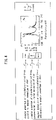
Fig. 4 . The method has the element-selectivity, that is, the method is capable of measuring the direction of magnetic moment for a specific element by adjusting X-ray energy with an excitation energy gap between specific electron orbital. - As shown in
Fig. 4 , an absorption spectrum changes in accordance with the direction of angular momentum of circular polarization light and the direction of angular momentum of atom. The basic magnetic properties such as orbital angular momentum, spin angular momentum and magnetic momentum can be measured from (1) the measurement of angular momentum of circular polarization X-ray and that of atom in the case both momentums are parallel; (2) the measurement of angular momentum of circular polarization X-ray and that of atom in the case both momentums are anti-paralle; (3) the difference between them, that is, XMCD. - As shown in
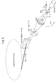
Fig. 5 , the present measurement system comprises a radiation source, a monochromator to disperse white radiation into monochromatic X-ray, an aperture slit to enter X-ray of the radiation source into an analytical section, the analytical section equipping a combination of Fresnel zone plate and order-sorting aperture to focus X-ray flux passing the aperture slit, a sample-stage to set a sample to be irradiated with X-ray and an X-ray-detector to detect transmission X-ray passing the sample; which is characterized by the measurement of X-ray magnetic circular dichroism of X-ray passing the sample within magnet field or nonmagnetic field. The XMCD at each sample place can be measured through precisely scanning the sample stage and using focused radiation light. - As shown in
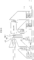
Fig. 6 , the present measurement apparatus comprises the aperture slit, the analytical section equipping a combination of Fresnel zone plate (FZP) and order-sorting aperture (OSA) to focus X-ray flux passing the aperture slit, the sample-stage to set a sample to be irradiated with X-ray and the X-ray-detector equipping the Avalanche photodiode to detect transmittance of transmission X-ray passing the sample. The FZP, OSA, sample-stage and X-ray-detector are equipping piezoelectric devices, therefore their X-, Y- and Z-stages can be controlled to an accuracy of nanometers. For the efficient X-ray detection under a vacuum and magnetic field, the Avalanche photodiode (APD) having dynamic ranges and optical fibers which is used within external magnetic field is preferable. Also, the exclusion of heat-generating parts such as mortars and laser prevents the resolution of APD from thermal drift. Therefore, such exclusion is necessary to measure XMCD of a single particle in the nano-crystalline magnet. In addition, for the measurement in the magnetic field, a combination system of superconductive magnet and use of non-magnetic parts and devices is preferable. - A bulk sample of Nd2Fe14B or Sm2Fe17N3 is used as the sample. The sample is fabricated using focused ion beams, followed by measuring X-ray transmittance at each sample position. The measurement of X-ray transmittance for the Nd2Fe14B sample or Sm2Fe17N3 sample is based on the Nd-absorption-edge X-ray energy (980.4 eV) or Sm-absorption-edge X-ray energy (1083.3 eV), respectively. The result is shown in
Fig. 7 . - From the result of
Fig. 7 , it is found that the Nd2Fe14B sample is measurable in the range 750 nm or less, 500 nm or less, 100 nm or less in thickness and that the Sm2Fe17N3 sample is measurable in therange 1000 nm or less, 500 nm or less, 100 nm or less in thickness. - A bulk sample of Nd-Fe-B magnet is used for the sample. A TEM image (
Fig. 8 ) of lateral face of the sample is observed. FromFig. 8 , the observed crystalline particle is estimated to be about 50 nm∼100 nm in size. - Next, the fabricated sample as shown in
Fig. 9 is etched using focused ion beam. X-ray transmittance of the obtained sample is measured, followed by determining thickness distribution as shown inFig 10 . The thickness of the sample can be determined from the following equation.

- As shown in
Fig. 10 , the sample is found to be fabricated into 50 nm in thickness. - Next, the fabricated sample is irradiated with circular polarization X-ray, followed by measuring magnetic characteristic.
Fig. 11 shows a XMCD space distribution. InFig. 11 , the difference in contrasting density of white and black colors shows the difference for the direction of magnetic moment corresponding to the magnetic domain phase of magnetic body. The magnetic characteristic at the part (A) inFig. 11 is found to have two peaks at 981 eV and 1003 eV, respectively, as shown inFig. 12 . From the spectrum analysis, it is found that the magnetism property such as spin magnetic momentum and orbital magnetic momentum can be measured for a single crystal particle. -
- 1
-
sample 1 - 2
- focused ion beam
- 3
- X-ray
Claims (5)
- A magnetic measurement method characterized by the measurement of magnetic characteristic of a sample of 50 nm in thickness by irradiating the sample with X-rays and detecting X-rays passing the sample, wherein circular polarization X-rays focused into 10 nm in beam size are used,
whereinwhile the sample is placed within an applied external magnetic field, the sample is alternately irradiated with right-circular polarization X-rays and left-circular polarization X-rays, absorption of both right-circular and left-circular polarization X-rays is measured, respectively, and the difference between the two X-ray absorptions, i.e. X-ray magnetic circular dichroism, is detected, orwhile the sample is placed within an applied external magnetic field, X-ray absorption of the sample parallel to the magnetic field direction and X-ray absorption of the sample anti-parallel to the magnetic field direction are measured, respectively, and the difference between said two X-ray absorptions is detected. - The magnetic measurement method according to claim 1, which is characterized by the sample being fabricated into microtome section of 50 nm in thickness using focused ion beam etching.
- A magnetic measurement system to perform the magnetic measurement method of claim 1 or claim 2, comprising: an X-ray source, means for applying an external magnetic field, a monochromator to monochromatise white radiation into monochromatic X-rays, an aperture slit to pass X-rays from the radiation source into an analytical section, the analytical section comprising a combination of a Fresnel zone plate and an order-sorting aperture to focus X-ray flux passing the aperture slit into 10 nm in beam size, a sample-stage to set a sample to be irradiated with X-rays and an X-ray-detector to detect transmission X-rays passing the sample; said system being configured to introduce transmission X-rays passing the sample into the X-ray-detector, and to detect X-ray magnetic circular dichroism in the X-ray-detector to measure a magnetic characteristic of the sample.
- The magnetic measurement system of claim 3, wherein the X-ray-detector comprises an Avalanche photodiode to detect transmission X-rays passing the sample.
- The magnetic measurement system of claim 3 or 4, wherein the Fresnel zone plate, the order-sorting aperture, the sample-stage and the X-ray detector comprise piezoelectric devices to control respective X-, Y- and Z-stages.
Applications Claiming Priority (1)
| Application Number | Priority Date | Filing Date | Title |
|---|---|---|---|
| JP2013198163A JP6411722B2 (en) | 2013-09-25 | 2013-09-25 | Magnetic property measurement method |
Publications (2)
| Publication Number | Publication Date |
|---|---|
| EP2853886A1 EP2853886A1 (en) | 2015-04-01 |
| EP2853886B1 true EP2853886B1 (en) | 2022-12-07 |
Family
ID=51589212
Family Applications (1)
| Application Number | Title | Priority Date | Filing Date |
|---|---|---|---|
| EP14186380.3A Active EP2853886B1 (en) | 2013-09-25 | 2014-09-25 | Magnetic measurement method and system |
Country Status (3)
| Country | Link |
|---|---|
| US (1) | US9766190B2 (en) |
| EP (1) | EP2853886B1 (en) |
| JP (1) | JP6411722B2 (en) |
Families Citing this family (3)
| Publication number | Priority date | Publication date | Assignee | Title |
|---|---|---|---|---|
| WO2019182097A1 (en) * | 2018-03-22 | 2019-09-26 | 国立研究開発法人量子科学技術研究開発機構 | Magnetic body observation method, and magnetic body observation device |
| CN108918424B (en) * | 2018-04-24 | 2020-10-02 | 金华职业技术学院 | Magnetic domain imaging method and magnetic domain wall shape discrimination method for magnetic wire |
| CN114563429B (en) * | 2022-03-25 | 2022-11-29 | 深圳技术大学 | Super-resolution X-ray shadow imaging system and imaging method thereof |
Family Cites Families (16)
| Publication number | Priority date | Publication date | Assignee | Title |
|---|---|---|---|---|
| US4003663A (en) * | 1971-02-26 | 1977-01-18 | Yeda Research & Development Co., Ltd. | Device for calibrating instrument that measures circular dichroism or circularly polarized luminescence |
| US3967902A (en) * | 1971-02-26 | 1976-07-06 | Yeda Research & Development Co. Ltd. | Method and apparatus for investigating the conformation of optically active molecules by measuring parameters associated with their luminescence |
| JPH0545304A (en) * | 1991-08-20 | 1993-02-23 | Hitachi Ltd | Method and apparatus for observing magnetic domain using circularly polarized light of x ray |
| WO2000072330A1 (en) * | 1999-05-24 | 2000-11-30 | Jmar Research, Inc. | Parallel x-ray nanotomography |
| US7338168B2 (en) * | 2001-07-06 | 2008-03-04 | Palantyr Research, Llc | Particle analyzing system and methodology |
| US6917472B1 (en) * | 2001-11-09 | 2005-07-12 | Xradia, Inc. | Achromatic fresnel optics for ultraviolet and x-ray radiation |
| JP2004037204A (en) * | 2002-07-02 | 2004-02-05 | Hamamatsu Photonics Kk | X-ray detector and inspection system having the same |
| US7864415B2 (en) * | 2007-09-17 | 2011-01-04 | U Chicago Argonne, Llc | Use of a focusing vortex lens as the objective in spiral phase contrast microscopy |
| JP5181150B2 (en) * | 2008-04-09 | 2013-04-10 | 独立行政法人科学技術振興機構 | Surface analysis method |
| JP2010151455A (en) | 2008-12-24 | 2010-07-08 | Toyota Central R&D Labs Inc | Observing method of magnetic sample, observing device, and observing tool thereof |
| JP2010278682A (en) * | 2009-05-27 | 2010-12-09 | Nippon Hoso Kyokai <Nhk> | X-ray imaging device |
| JP5589578B2 (en) * | 2010-06-10 | 2014-09-17 | 富士通株式会社 | X-ray analyzer |
| JP5228027B2 (en) | 2010-11-08 | 2013-07-03 | 株式会社日立ハイテクノロジーズ | Charged particle beam apparatus and sample preparation method |
| JP5644032B2 (en) | 2011-01-14 | 2014-12-24 | 株式会社日立産機システム | Method and apparatus for measuring magnetic properties of ferromagnetic materials |
| JP2012168027A (en) * | 2011-02-15 | 2012-09-06 | Sumitomo Metal Mining Co Ltd | Method of preparing sample for electron microscope |
| ES2439167B1 (en) * | 2012-06-21 | 2014-11-17 | Consejo Superior De Investigaciones Científicas (Csic) | Compounds with magnetic functionality, implants or gels derived from them, and the use of both to determine the enzymatic activity of an enzyme |
-
2013
- 2013-09-25 JP JP2013198163A patent/JP6411722B2/en active Active
-
2014
- 2014-09-25 US US14/496,966 patent/US9766190B2/en active Active
- 2014-09-25 EP EP14186380.3A patent/EP2853886B1/en active Active
Non-Patent Citations (1)
| Title |
|---|
| Y.U. IDZERDA ET AL: "Soft X-ray magnetic circular dichroism and magnetic films", NUCLEAR INSTRUMENTS & METHODS IN PHYSICS RESEARCH. SECTION A: ACCELERATORS, SPECTROMETERS, DETECTORS, AND ASSOCIATED EQUIPMENT, vol. 347, no. 1-3, 1 August 1994 (1994-08-01), NL, pages 134 - 141, XP055477818, ISSN: 0168-9002, DOI: 10.1016/0168-9002(94)91869-4 * |
Also Published As
| Publication number | Publication date |
|---|---|
| JP2015064280A (en) | 2015-04-09 |
| JP6411722B2 (en) | 2018-10-24 |
| EP2853886A1 (en) | 2015-04-01 |
| US20150084622A1 (en) | 2015-03-26 |
| US9766190B2 (en) | 2017-09-19 |
Similar Documents
| Publication | Publication Date | Title |
|---|---|---|
| Tusche et al. | Spin resolved photoelectron microscopy using a two-dimensional spin-polarizing electron mirror | |
| Hitchcock | Soft X-ray spectromicroscopy and ptychography | |
| JP7129109B2 (en) | Magnetic substance observation method and magnetic substance observation device | |
| EP2853886B1 (en) | Magnetic measurement method and system | |
| JP2008218063A (en) | Transmission electron microscope | |
| Popescu et al. | COMET: a new end-station at SOLEIL for coherent magnetic scattering in transmission | |
| JP2010003450A (en) | Scanning electron microscope | |
| Tinti et al. | The EIGER detector for low-energy electron microscopy and photoemission electron microscopy | |
| Agui et al. | Application of magnetic Compton scattering for spin-specific magnetic hysteresis measurement | |
| Guo et al. | Characterization of spectroscopic photoemission and low energy electron microscope using multipolarized soft x rays at BL17SU/SPring-8 | |
| US9835569B2 (en) | Magnetic measurement system and apparatus utilizing X-ray to measure comparatively thick magnetic materials | |
| Le Thomas et al. | Imaging of high-Q cavity optical modes by electron energy-loss microscopy | |
| Ślęzak et al. | Prospects of X‐ray photoemission electron microscopy at the first beamline of the Polish synchrotron facility ‘Solaris’ | |
| Tonner et al. | X-ray photoemission electron microscopy: Magnetic circular dichroism imaging and other contrast mechanisms | |
| Sugawara et al. | Bulk-sensitive magnetic microscope utilizing x-ray magnetic circularly polarized emission | |
| Quitmann et al. | Measuring magnetic excitations in microstructures using X-ray microscopy | |
| Escher et al. | 2D imaging spin-filter for NanoESCA based on Au/Ir (001) or Fe (001)-p (1× 1) O | |
| Schümmer et al. | A scanning reflection X-ray microscope for magnetic imaging in the EUV range | |
| Ueda et al. | Magnetic microstructures of neodymium in Nd2Fe14B permanent magnet by hard x-ray magnetic-circular dichroism using focused x-ray beam | |
| Kozhevnikov et al. | Neutron channeling in a nonmagnetic planar waveguide | |
| Petrov et al. | Pro-jecting classical Mott polarimeter, St | |
| WO2022118957A1 (en) | Magnetization measurement method | |
| US20230314348A1 (en) | Spin-resolved ultrafast electron diffraction | |
| Bukin | Time-resolved imaging of magnetisation dynamics using x-ray holography with extended reference and autocorrelation by linear differential operator (HERALDO) | |
| Samarin et al. | Electronic structure of thin cobalt film on W (1 1 0) by spin-polarized two-electron spectroscopy |
Legal Events
| Date | Code | Title | Description |
|---|---|---|---|
| PUAI | Public reference made under article 153(3) epc to a published international application that has entered the european phase |
Free format text: ORIGINAL CODE: 0009012 |
|
| 17P | Request for examination filed |
Effective date: 20140925 |
|
| AK | Designated contracting states |
Kind code of ref document: A1 Designated state(s): AL AT BE BG CH CY CZ DE DK EE ES FI FR GB GR HR HU IE IS IT LI LT LU LV MC MK MT NL NO PL PT RO RS SE SI SK SM TR |
|
| AX | Request for extension of the european patent |
Extension state: BA ME |
|
| R17P | Request for examination filed (corrected) |
Effective date: 20150312 |
|
| RBV | Designated contracting states (corrected) |
Designated state(s): AL AT BE BG CH CY CZ DE DK EE ES FI FR GB GR HR HU IE IS IT LI LT LU LV MC MK MT NL NO PL PT RO RS SE SI SK SM TR |
|
| STAA | Information on the status of an ep patent application or granted ep patent |
Free format text: STATUS: EXAMINATION IS IN PROGRESS |
|
| 17Q | First examination report despatched |
Effective date: 20180529 |
|
| STAA | Information on the status of an ep patent application or granted ep patent |
Free format text: STATUS: EXAMINATION IS IN PROGRESS |
|
| STAA | Information on the status of an ep patent application or granted ep patent |
Free format text: STATUS: EXAMINATION IS IN PROGRESS |
|
| GRAP | Despatch of communication of intention to grant a patent |
Free format text: ORIGINAL CODE: EPIDOSNIGR1 |
|
| STAA | Information on the status of an ep patent application or granted ep patent |
Free format text: STATUS: GRANT OF PATENT IS INTENDED |
|
| RIC1 | Information provided on ipc code assigned before grant |
Ipc: G01N 23/085 20180101ALI20220621BHEP Ipc: G01N 23/04 20060101AFI20220621BHEP |
|
| INTG | Intention to grant announced |
Effective date: 20220705 |
|
| GRAS | Grant fee paid |
Free format text: ORIGINAL CODE: EPIDOSNIGR3 |
|
| GRAA | (expected) grant |
Free format text: ORIGINAL CODE: 0009210 |
|
| STAA | Information on the status of an ep patent application or granted ep patent |
Free format text: STATUS: THE PATENT HAS BEEN GRANTED |
|
| AK | Designated contracting states |
Kind code of ref document: B1 Designated state(s): AL AT BE BG CH CY CZ DE DK EE ES FI FR GB GR HR HU IE IS IT LI LT LU LV MC MK MT NL NO PL PT RO RS SE SI SK SM TR |
|
| REG | Reference to a national code |
Ref country code: GB Ref legal event code: FG4D |
|
| REG | Reference to a national code |
Ref country code: CH Ref legal event code: EP Ref country code: AT Ref legal event code: REF Ref document number: 1536587 Country of ref document: AT Kind code of ref document: T Effective date: 20221215 |
|
| REG | Reference to a national code |
Ref country code: DE Ref legal event code: R096 Ref document number: 602014085718 Country of ref document: DE |
|
| REG | Reference to a national code |
Ref country code: IE Ref legal event code: FG4D |
|
| REG | Reference to a national code |
Ref country code: LT Ref legal event code: MG9D |
|
| REG | Reference to a national code |
Ref country code: NL Ref legal event code: MP Effective date: 20221207 |
|
| PG25 | Lapsed in a contracting state [announced via postgrant information from national office to epo] |
Ref country code: SE Free format text: LAPSE BECAUSE OF FAILURE TO SUBMIT A TRANSLATION OF THE DESCRIPTION OR TO PAY THE FEE WITHIN THE PRESCRIBED TIME-LIMIT Effective date: 20221207 Ref country code: NO Free format text: LAPSE BECAUSE OF FAILURE TO SUBMIT A TRANSLATION OF THE DESCRIPTION OR TO PAY THE FEE WITHIN THE PRESCRIBED TIME-LIMIT Effective date: 20230307 Ref country code: LT Free format text: LAPSE BECAUSE OF FAILURE TO SUBMIT A TRANSLATION OF THE DESCRIPTION OR TO PAY THE FEE WITHIN THE PRESCRIBED TIME-LIMIT Effective date: 20221207 Ref country code: FI Free format text: LAPSE BECAUSE OF FAILURE TO SUBMIT A TRANSLATION OF THE DESCRIPTION OR TO PAY THE FEE WITHIN THE PRESCRIBED TIME-LIMIT Effective date: 20221207 Ref country code: ES Free format text: LAPSE BECAUSE OF FAILURE TO SUBMIT A TRANSLATION OF THE DESCRIPTION OR TO PAY THE FEE WITHIN THE PRESCRIBED TIME-LIMIT Effective date: 20221207 |
|
| REG | Reference to a national code |
Ref country code: AT Ref legal event code: MK05 Ref document number: 1536587 Country of ref document: AT Kind code of ref document: T Effective date: 20221207 |
|
| PG25 | Lapsed in a contracting state [announced via postgrant information from national office to epo] |
Ref country code: RS Free format text: LAPSE BECAUSE OF FAILURE TO SUBMIT A TRANSLATION OF THE DESCRIPTION OR TO PAY THE FEE WITHIN THE PRESCRIBED TIME-LIMIT Effective date: 20221207 Ref country code: PL Free format text: LAPSE BECAUSE OF FAILURE TO SUBMIT A TRANSLATION OF THE DESCRIPTION OR TO PAY THE FEE WITHIN THE PRESCRIBED TIME-LIMIT Effective date: 20221207 Ref country code: LV Free format text: LAPSE BECAUSE OF FAILURE TO SUBMIT A TRANSLATION OF THE DESCRIPTION OR TO PAY THE FEE WITHIN THE PRESCRIBED TIME-LIMIT Effective date: 20221207 Ref country code: HR Free format text: LAPSE BECAUSE OF FAILURE TO SUBMIT A TRANSLATION OF THE DESCRIPTION OR TO PAY THE FEE WITHIN THE PRESCRIBED TIME-LIMIT Effective date: 20221207 Ref country code: GR Free format text: LAPSE BECAUSE OF FAILURE TO SUBMIT A TRANSLATION OF THE DESCRIPTION OR TO PAY THE FEE WITHIN THE PRESCRIBED TIME-LIMIT Effective date: 20230308 |
|
| PG25 | Lapsed in a contracting state [announced via postgrant information from national office to epo] |
Ref country code: NL Free format text: LAPSE BECAUSE OF FAILURE TO SUBMIT A TRANSLATION OF THE DESCRIPTION OR TO PAY THE FEE WITHIN THE PRESCRIBED TIME-LIMIT Effective date: 20221207 |
|
| PG25 | Lapsed in a contracting state [announced via postgrant information from national office to epo] |
Ref country code: SM Free format text: LAPSE BECAUSE OF FAILURE TO SUBMIT A TRANSLATION OF THE DESCRIPTION OR TO PAY THE FEE WITHIN THE PRESCRIBED TIME-LIMIT Effective date: 20221207 Ref country code: RO Free format text: LAPSE BECAUSE OF FAILURE TO SUBMIT A TRANSLATION OF THE DESCRIPTION OR TO PAY THE FEE WITHIN THE PRESCRIBED TIME-LIMIT Effective date: 20221207 Ref country code: PT Free format text: LAPSE BECAUSE OF FAILURE TO SUBMIT A TRANSLATION OF THE DESCRIPTION OR TO PAY THE FEE WITHIN THE PRESCRIBED TIME-LIMIT Effective date: 20230410 Ref country code: EE Free format text: LAPSE BECAUSE OF FAILURE TO SUBMIT A TRANSLATION OF THE DESCRIPTION OR TO PAY THE FEE WITHIN THE PRESCRIBED TIME-LIMIT Effective date: 20221207 Ref country code: CZ Free format text: LAPSE BECAUSE OF FAILURE TO SUBMIT A TRANSLATION OF THE DESCRIPTION OR TO PAY THE FEE WITHIN THE PRESCRIBED TIME-LIMIT Effective date: 20221207 Ref country code: AT Free format text: LAPSE BECAUSE OF FAILURE TO SUBMIT A TRANSLATION OF THE DESCRIPTION OR TO PAY THE FEE WITHIN THE PRESCRIBED TIME-LIMIT Effective date: 20221207 |
|
| PG25 | Lapsed in a contracting state [announced via postgrant information from national office to epo] |
Ref country code: SK Free format text: LAPSE BECAUSE OF FAILURE TO SUBMIT A TRANSLATION OF THE DESCRIPTION OR TO PAY THE FEE WITHIN THE PRESCRIBED TIME-LIMIT Effective date: 20221207 Ref country code: IS Free format text: LAPSE BECAUSE OF FAILURE TO SUBMIT A TRANSLATION OF THE DESCRIPTION OR TO PAY THE FEE WITHIN THE PRESCRIBED TIME-LIMIT Effective date: 20230407 Ref country code: AL Free format text: LAPSE BECAUSE OF FAILURE TO SUBMIT A TRANSLATION OF THE DESCRIPTION OR TO PAY THE FEE WITHIN THE PRESCRIBED TIME-LIMIT Effective date: 20221207 |
|
| REG | Reference to a national code |
Ref country code: DE Ref legal event code: R097 Ref document number: 602014085718 Country of ref document: DE |
|
| PLBE | No opposition filed within time limit |
Free format text: ORIGINAL CODE: 0009261 |
|
| STAA | Information on the status of an ep patent application or granted ep patent |
Free format text: STATUS: NO OPPOSITION FILED WITHIN TIME LIMIT |
|
| PG25 | Lapsed in a contracting state [announced via postgrant information from national office to epo] |
Ref country code: DK Free format text: LAPSE BECAUSE OF FAILURE TO SUBMIT A TRANSLATION OF THE DESCRIPTION OR TO PAY THE FEE WITHIN THE PRESCRIBED TIME-LIMIT Effective date: 20221207 |
|
| PGFP | Annual fee paid to national office [announced via postgrant information from national office to epo] |
Ref country code: GB Payment date: 20230803 Year of fee payment: 10 |
|
| 26N | No opposition filed |
Effective date: 20230908 |
|
| PG25 | Lapsed in a contracting state [announced via postgrant information from national office to epo] |
Ref country code: SI Free format text: LAPSE BECAUSE OF FAILURE TO SUBMIT A TRANSLATION OF THE DESCRIPTION OR TO PAY THE FEE WITHIN THE PRESCRIBED TIME-LIMIT Effective date: 20221207 |
|
| PGFP | Annual fee paid to national office [announced via postgrant information from national office to epo] |
Ref country code: FR Payment date: 20230808 Year of fee payment: 10 Ref country code: DE Payment date: 20230802 Year of fee payment: 10 |
|
| REG | Reference to a national code |
Ref country code: DE Ref legal event code: R084 Ref document number: 602014085718 Country of ref document: DE |
|
| REG | Reference to a national code |
Ref country code: GB Ref legal event code: 746 Effective date: 20240222 |