EP2853824B1 - Air-conditioning system - Google Patents
Air-conditioning system Download PDFInfo
- Publication number
- EP2853824B1 EP2853824B1 EP14182544.8A EP14182544A EP2853824B1 EP 2853824 B1 EP2853824 B1 EP 2853824B1 EP 14182544 A EP14182544 A EP 14182544A EP 2853824 B1 EP2853824 B1 EP 2853824B1
- Authority
- EP
- European Patent Office
- Prior art keywords
- air
- information
- adapter
- conditioning apparatus
- test operation
- Prior art date
- Legal status (The legal status is an assumption and is not a legal conclusion. Google has not performed a legal analysis and makes no representation as to the accuracy of the status listed.)
- Active
Links
- 238000004378 air conditioning Methods 0.000 title claims description 99
- 238000012360 testing method Methods 0.000 claims description 73
- 239000003507 refrigerant Substances 0.000 description 32
- 230000008859 change Effects 0.000 description 16
- 238000000034 method Methods 0.000 description 11
- 230000008569 process Effects 0.000 description 7
- 230000004044 response Effects 0.000 description 7
- 238000001816 cooling Methods 0.000 description 6
- 238000010586 diagram Methods 0.000 description 6
- 239000000428 dust Substances 0.000 description 6
- 238000010438 heat treatment Methods 0.000 description 6
- 238000004891 communication Methods 0.000 description 4
- 238000012423 maintenance Methods 0.000 description 4
- 238000012544 monitoring process Methods 0.000 description 4
- 230000015556 catabolic process Effects 0.000 description 3
- 238000006731 degradation reaction Methods 0.000 description 3
- 239000000470 constituent Substances 0.000 description 2
- 238000005057 refrigeration Methods 0.000 description 2
- 230000008439 repair process Effects 0.000 description 2
- 239000007787 solid Substances 0.000 description 2
- 230000007704 transition Effects 0.000 description 2
- 230000005856 abnormality Effects 0.000 description 1
- 230000005540 biological transmission Effects 0.000 description 1
- 230000001143 conditioned effect Effects 0.000 description 1
- 230000000694 effects Effects 0.000 description 1
- 230000006870 function Effects 0.000 description 1
Images


Classifications
-
- F—MECHANICAL ENGINEERING; LIGHTING; HEATING; WEAPONS; BLASTING
- F24—HEATING; RANGES; VENTILATING
- F24F—AIR-CONDITIONING; AIR-HUMIDIFICATION; VENTILATION; USE OF AIR CURRENTS FOR SCREENING
- F24F11/00—Control or safety arrangements
- F24F11/30—Control or safety arrangements for purposes related to the operation of the system, e.g. for safety or monitoring
- F24F11/49—Control or safety arrangements for purposes related to the operation of the system, e.g. for safety or monitoring ensuring correct operation, e.g. by trial operation or configuration checks
-
- F—MECHANICAL ENGINEERING; LIGHTING; HEATING; WEAPONS; BLASTING
- F24—HEATING; RANGES; VENTILATING
- F24F—AIR-CONDITIONING; AIR-HUMIDIFICATION; VENTILATION; USE OF AIR CURRENTS FOR SCREENING
- F24F1/00—Room units for air-conditioning, e.g. separate or self-contained units or units receiving primary air from a central station
- F24F1/0003—Room units for air-conditioning, e.g. separate or self-contained units or units receiving primary air from a central station characterised by a split arrangement, wherein parts of the air-conditioning system, e.g. evaporator and condenser, are in separately located units
-
- F—MECHANICAL ENGINEERING; LIGHTING; HEATING; WEAPONS; BLASTING
- F24—HEATING; RANGES; VENTILATING
- F24F—AIR-CONDITIONING; AIR-HUMIDIFICATION; VENTILATION; USE OF AIR CURRENTS FOR SCREENING
- F24F1/00—Room units for air-conditioning, e.g. separate or self-contained units or units receiving primary air from a central station
- F24F1/06—Separate outdoor units, e.g. outdoor unit to be linked to a separate room comprising a compressor and a heat exchanger
-
- F—MECHANICAL ENGINEERING; LIGHTING; HEATING; WEAPONS; BLASTING
- F24—HEATING; RANGES; VENTILATING
- F24F—AIR-CONDITIONING; AIR-HUMIDIFICATION; VENTILATION; USE OF AIR CURRENTS FOR SCREENING
- F24F11/00—Control or safety arrangements
- F24F11/30—Control or safety arrangements for purposes related to the operation of the system, e.g. for safety or monitoring
-
- F—MECHANICAL ENGINEERING; LIGHTING; HEATING; WEAPONS; BLASTING
- F24—HEATING; RANGES; VENTILATING
- F24F—AIR-CONDITIONING; AIR-HUMIDIFICATION; VENTILATION; USE OF AIR CURRENTS FOR SCREENING
- F24F11/00—Control or safety arrangements
- F24F11/50—Control or safety arrangements characterised by user interfaces or communication
- F24F11/52—Indication arrangements, e.g. displays
-
- F—MECHANICAL ENGINEERING; LIGHTING; HEATING; WEAPONS; BLASTING
- F24—HEATING; RANGES; VENTILATING
- F24F—AIR-CONDITIONING; AIR-HUMIDIFICATION; VENTILATION; USE OF AIR CURRENTS FOR SCREENING
- F24F11/00—Control or safety arrangements
- F24F11/50—Control or safety arrangements characterised by user interfaces or communication
- F24F11/56—Remote control
-
- F—MECHANICAL ENGINEERING; LIGHTING; HEATING; WEAPONS; BLASTING
- F24—HEATING; RANGES; VENTILATING
- F24F—AIR-CONDITIONING; AIR-HUMIDIFICATION; VENTILATION; USE OF AIR CURRENTS FOR SCREENING
- F24F11/00—Control or safety arrangements
- F24F11/62—Control or safety arrangements characterised by the type of control or by internal processing, e.g. using fuzzy logic, adaptive control or estimation of values
-
- F—MECHANICAL ENGINEERING; LIGHTING; HEATING; WEAPONS; BLASTING
- F24—HEATING; RANGES; VENTILATING
- F24F—AIR-CONDITIONING; AIR-HUMIDIFICATION; VENTILATION; USE OF AIR CURRENTS FOR SCREENING
- F24F11/00—Control or safety arrangements
- F24F11/70—Control systems characterised by their outputs; Constructional details thereof
- F24F11/72—Control systems characterised by their outputs; Constructional details thereof for controlling the supply of treated air, e.g. its pressure
- F24F11/74—Control systems characterised by their outputs; Constructional details thereof for controlling the supply of treated air, e.g. its pressure for controlling air flow rate or air velocity
- F24F11/77—Control systems characterised by their outputs; Constructional details thereof for controlling the supply of treated air, e.g. its pressure for controlling air flow rate or air velocity by controlling the speed of ventilators
-
- F—MECHANICAL ENGINEERING; LIGHTING; HEATING; WEAPONS; BLASTING
- F24—HEATING; RANGES; VENTILATING
- F24F—AIR-CONDITIONING; AIR-HUMIDIFICATION; VENTILATION; USE OF AIR CURRENTS FOR SCREENING
- F24F11/00—Control or safety arrangements
- F24F11/70—Control systems characterised by their outputs; Constructional details thereof
- F24F11/72—Control systems characterised by their outputs; Constructional details thereof for controlling the supply of treated air, e.g. its pressure
- F24F11/79—Control systems characterised by their outputs; Constructional details thereof for controlling the supply of treated air, e.g. its pressure for controlling the direction of the supplied air
-
- F—MECHANICAL ENGINEERING; LIGHTING; HEATING; WEAPONS; BLASTING
- F24—HEATING; RANGES; VENTILATING
- F24F—AIR-CONDITIONING; AIR-HUMIDIFICATION; VENTILATION; USE OF AIR CURRENTS FOR SCREENING
- F24F11/00—Control or safety arrangements
- F24F11/70—Control systems characterised by their outputs; Constructional details thereof
- F24F11/80—Control systems characterised by their outputs; Constructional details thereof for controlling the temperature of the supplied air
- F24F11/83—Control systems characterised by their outputs; Constructional details thereof for controlling the temperature of the supplied air by controlling the supply of heat-exchange fluids to heat-exchangers
- F24F11/84—Control systems characterised by their outputs; Constructional details thereof for controlling the temperature of the supplied air by controlling the supply of heat-exchange fluids to heat-exchangers using valves
-
- F—MECHANICAL ENGINEERING; LIGHTING; HEATING; WEAPONS; BLASTING
- F24—HEATING; RANGES; VENTILATING
- F24F—AIR-CONDITIONING; AIR-HUMIDIFICATION; VENTILATION; USE OF AIR CURRENTS FOR SCREENING
- F24F11/00—Control or safety arrangements
- F24F11/70—Control systems characterised by their outputs; Constructional details thereof
- F24F11/80—Control systems characterised by their outputs; Constructional details thereof for controlling the temperature of the supplied air
- F24F11/86—Control systems characterised by their outputs; Constructional details thereof for controlling the temperature of the supplied air by controlling compressors within refrigeration or heat pump circuits
-
- F—MECHANICAL ENGINEERING; LIGHTING; HEATING; WEAPONS; BLASTING
- F24—HEATING; RANGES; VENTILATING
- F24F—AIR-CONDITIONING; AIR-HUMIDIFICATION; VENTILATION; USE OF AIR CURRENTS FOR SCREENING
- F24F11/00—Control or safety arrangements
- F24F11/89—Arrangement or mounting of control or safety devices
-
- F—MECHANICAL ENGINEERING; LIGHTING; HEATING; WEAPONS; BLASTING
- F25—REFRIGERATION OR COOLING; COMBINED HEATING AND REFRIGERATION SYSTEMS; HEAT PUMP SYSTEMS; MANUFACTURE OR STORAGE OF ICE; LIQUEFACTION SOLIDIFICATION OF GASES
- F25B—REFRIGERATION MACHINES, PLANTS OR SYSTEMS; COMBINED HEATING AND REFRIGERATION SYSTEMS; HEAT PUMP SYSTEMS
- F25B41/00—Fluid-circulation arrangements
- F25B41/30—Expansion means; Dispositions thereof
-
- F—MECHANICAL ENGINEERING; LIGHTING; HEATING; WEAPONS; BLASTING
- F25—REFRIGERATION OR COOLING; COMBINED HEATING AND REFRIGERATION SYSTEMS; HEAT PUMP SYSTEMS; MANUFACTURE OR STORAGE OF ICE; LIQUEFACTION SOLIDIFICATION OF GASES
- F25B—REFRIGERATION MACHINES, PLANTS OR SYSTEMS; COMBINED HEATING AND REFRIGERATION SYSTEMS; HEAT PUMP SYSTEMS
- F25B49/00—Arrangement or mounting of control or safety devices
- F25B49/02—Arrangement or mounting of control or safety devices for compression type machines, plants or systems
-
- F—MECHANICAL ENGINEERING; LIGHTING; HEATING; WEAPONS; BLASTING
- F24—HEATING; RANGES; VENTILATING
- F24F—AIR-CONDITIONING; AIR-HUMIDIFICATION; VENTILATION; USE OF AIR CURRENTS FOR SCREENING
- F24F11/00—Control or safety arrangements
- F24F11/50—Control or safety arrangements characterised by user interfaces or communication
- F24F11/56—Remote control
- F24F11/58—Remote control using Internet communication
-
- F—MECHANICAL ENGINEERING; LIGHTING; HEATING; WEAPONS; BLASTING
- F24—HEATING; RANGES; VENTILATING
- F24F—AIR-CONDITIONING; AIR-HUMIDIFICATION; VENTILATION; USE OF AIR CURRENTS FOR SCREENING
- F24F11/00—Control or safety arrangements
- F24F11/62—Control or safety arrangements characterised by the type of control or by internal processing, e.g. using fuzzy logic, adaptive control or estimation of values
- F24F11/63—Electronic processing
- F24F11/65—Electronic processing for selecting an operating mode
-
- F—MECHANICAL ENGINEERING; LIGHTING; HEATING; WEAPONS; BLASTING
- F24—HEATING; RANGES; VENTILATING
- F24F—AIR-CONDITIONING; AIR-HUMIDIFICATION; VENTILATION; USE OF AIR CURRENTS FOR SCREENING
- F24F2120/00—Control inputs relating to users or occupants
- F24F2120/20—Feedback from users
-
- F—MECHANICAL ENGINEERING; LIGHTING; HEATING; WEAPONS; BLASTING
- F25—REFRIGERATION OR COOLING; COMBINED HEATING AND REFRIGERATION SYSTEMS; HEAT PUMP SYSTEMS; MANUFACTURE OR STORAGE OF ICE; LIQUEFACTION SOLIDIFICATION OF GASES
- F25B—REFRIGERATION MACHINES, PLANTS OR SYSTEMS; COMBINED HEATING AND REFRIGERATION SYSTEMS; HEAT PUMP SYSTEMS
- F25B2600/00—Control issues
- F25B2600/07—Remote controls
Definitions
- the centralized management device 13 performs the following control operation to prevent the operation of the air-conditioning apparatus 100 from being changed as the user operates the operation terminal 9.
- the centralized management device 13 includes operation restricting means 13A and is capable of controlling the operation terminal 9.
- the operation restricting means 13A restricts an operation on the operation terminal 9 to prevent the operation of the air-conditioning apparatus 100 from being changed as the user operates the operation terminal 9 (refer to step S301 in Fig. 7 ; to be described later).
- the adapter 2 outputs the adapter information A held in itself to the centralized management device 13 via the router 8 and the Internet 12 (step S300).
- the centralized management device 13 determines whether the adapter information A output from the adapter 2 is associated with test operation switch information (step S301). If the centralized management device 13 determines that the information is associated with test operation switch information (YES in step S301), it returns the process to step S300.
Description
- The present invention relates to an air-conditioning system.
- A technique has conventionally been proposed which is associated with an air-conditioning apparatus that a user away from his or her house can remotely operate with a terminal, such as a mobile phone (refer to, for example, Patent Literature 1).
- With the technique disclosed in
Patent Literature 1, operation instructions which the user away from his or her house can issue via the terminal, such as a mobile phone, are restricted in accordance with details of an operation instruction issued through remote control by another user in his or her house. This prevents transition to an operation that is not intended by the other user in the house, for example, transition to a heating operation when the user away from the house operates as such while a cooling operation is performed when the other user in the house operates as such. - [Patent Literature 1] Japanese Unexamined Patent Application Publication No.
2007-24420 Fig. 3 ) -
EP2351971A describes that an air-conditioning monitoring system (1) includes an air conditioner that shifts to a normal operation after a test operation is executed and that is controlled by a remote controller; and a centralized monitoring apparatus (3) that collects operating information of the air conditioner, the air conditioner and the centralized monitoring apparatus (3) being connected via a network. The centralized monitoring apparatus (3) includes a permission data output section (30) that outputs the permission data to the air conditioner, when there is no abnormality in the test operation data obtained from the air conditioner. - Some air-conditioning apparatuses include a test operation switch that is used to determine whether the air-conditioning apparatus operates properly when a serviceperson checks or repairs the air-conditioning apparatus. When the serviceperson turns on the test operation switch, a program stored in a control unit in advance is started to operate, for example, an air-sending fan and air vanes of an indoor unit and a compressor of an outdoor unit in accordance with the program.
- The technique disclosed in
Patent Literature 1 has the following shortcomings: details of the operation of the air-conditioning apparatus may be changed remotely through a terminal, such as a mobile phone, during determination as to whether the air-conditioning apparatus operates properly after turn-on of the test operation switch. Specifically, according to the technique disclosed inPatent Literature 1, it is often hard for a serviceperson to check the air-conditioning apparatus. Disadvantageously, this leads to lowered ease of maintenance of the air-conditioning apparatus. - The present invention has been made to overcome the above-described disadvantage, and has as its object to provide an air-conditioning system that suppresses degradation in ease of maintenance. An air conditioner system according to the preamble of
claim 1 is known fromEP 2 351 971 A2 - The present invention provides an air-conditioning system including an air-conditioning apparatus that includes an indoor unit and an outdoor unit, an adapter connected to the indoor unit and configured to communicate with the indoor unit, and a centralized management device configured to communicate with an operation terminal to receive operation information for operating the air-conditioning apparatus from the operation terminal and further communicate directly with the adapter via an external network. The indoor unit includes a test operation switch configured to perform a test operation mode in which a preset operation is executed, and a control unit connected to the adapter and configured to perform the test operation mode when the test operation switch is turned on. The control unit includes mode control means for, when the test operation switch is turned on, transmitting information indicating that the test operation mode is performed to the centralized management device via the adapter and the external network. The centralized management device includes operation restricting means for, when the information indicating that the test operation mode is performed is received, restricting an operation on the operation terminal to prevent an operation of the air-conditioning apparatus from being changed via the operation terminal.
- Since the air-conditioning system according to the present invention has the above-described configuration, it can suppress degradation in ease of maintenance.
-
- [
Fig. 1] Fig. 1 is a schematic diagram showing an air-conditioning system including an air-conditioning apparatus according to Embodiment of the present invention. - [
Fig. 2] Fig. 2 illustrates diagrams for explaining the air-conditioning apparatus according to Embodiment of the present invention. - [
Fig. 3] Fig. 3 is a cross-sectional view of an indoor unit of the air-conditioning apparatus according to Embodiment of the present invention. - [
Fig. 4] Fig. 4 is a block diagram illustrating the air-conditioning system according to Embodiment of the present invention. - [
Fig. 5] Fig. 5 is a flowchart illustrating a first control sequence of the air-conditioning apparatus according to Embodiment of the present invention. - [
Fig. 6] Fig. 6 is a flowchart illustrating a second control sequence of the air-conditioning apparatus according to Embodiment of the present invention. - [
Fig. 7] Fig. 7 is a flowchart illustrating a third control sequence of the air-conditioning apparatus according to Embodiment of the present invention. - [
Fig. 8] Fig. 8 illustrates an exemplary message displayed on an operation terminal. - Embodiment of the present invention will now be described with reference to the accompanying drawings.
-
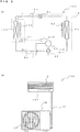
Fig. 1 is a schematic diagram illustrating an air-conditioning system 500 including an air-conditioning apparatus 100 according to Embodiment.Fig. 2 illustrates diagrams for explaining the air-conditioning apparatus 100 according to Embodiment.Fig. 3 is a cross-sectional view of anindoor unit 1 of the air-conditioning apparatus 100 according to Embodiment. The air-conditioning apparatus 100 and the air-conditioning system 500 including the air-conditioning apparatus 100 will be described with reference toFigs. 1 to 3 . - As illustrated in
Fig. 1 , the air-conditioning system 500 includes the air-conditioning apparatus 100 including acontroller 7, anadapter 2 connected to the air-conditioning apparatus 100, arouter 8 to communicate with theadapter 2, acentralized management device 13 to communicate with therouter 8 via anexternal network 11, and an operation terminal 9 (for example, a mobile phone) to communicate with thecentralized management device 13. - The air-
conditioning apparatus 100 includes theindoor unit 1 to supply conditioned air to an air-conditioned space (for example, a room in a house, a warehouse, or a room in a building), and anoutdoor unit 1B including, for example, an expansion device 51 and a compressor 52. Theindoor unit 1 is connected to theoutdoor unit 1B byrefrigerant pipes 63. - The
indoor unit 1 is installed in, for example, ahouse 10. Theindoor unit 1 includes an air-sendingfan 106 to supply air to an air-conditioned space (for example, a room, a warehouse, or a room in a building), anair vane unit 107 used to adjust the direction of air blown from the air-sendingfan 106, and anindoor heat exchanger 108 to be supplied with a refrigerant. Theindoor unit 1 further includes areception unit 3 to receive remote control information from thecontroller 7 which is an accessory to theindoor unit 1, atest operation switch 50 to allow theindoor unit 1 to perform a preset operation, and acontrol unit 21 electrically connected to thereception unit 3 and thetest operation switch 50. Theair vane unit 107 includes, for example, rotatable air vanes and a motor that rotates the air vanes. Although the following description assumes that thecontroller 7 is implemented using a remote controller capable of remotely operating the air-conditioning apparatus 100, thecontroller 7 is not limited to such an example. Thecontroller 7 may be connected to theindoor unit 1 by wire. - The
test operation switch 50 is used by a serviceperson to determine whether theindoor unit 1 operates properly in order to check or examine the air-conditioning apparatus 100. Specifically, thecontrol unit 21 includes a program to set, for example, each of the rotation speed (including ON/OFF) of the air-sendingfan 106, the angle of theair vane unit 107, the opening degree of the expansion device 51, and the rotation speed (including ON/OFF) of the compressor 52 to a preset value in order to check the operation of theindoor unit 1 or perform other operations involved. When the serviceperson turns on thetest operation switch 50, thecontrol unit 21 executes this program, thus driving, for example, the air-sendingfan 106. Thecontrol unit 21 will be described in detail later with reference toFig. 4 . - The
outdoor unit 1B is installed in an outdoor space, for example, on the roof of a building. Theoutdoor unit 1B includes the expansion device 51 to reduce the pressure of the refrigerant, the compressor 52 to compress the refrigerant, a four-way valve 53 to switch the flow path of the refrigerant, an outdoor heat exchanger 54 that functions as an evaporator in a heating operation and as a condenser (radiator) in a cooling operation, and an outdoor air-sending fan 55, which is provided to the outdoor heat exchanger 54, to supply air to the outdoor heat exchanger 54. - The
outdoor unit 1B further includes an outdoor-unit control unit 21B electrically connected to thecontrol unit 21. The outdoor-unit control unit 21B exchanges information with thecontrol unit 21. The outdoor-unit control unit 21B is disposed in, for example, an electrical component box (not illustrated) placed in the upper portion of a compressor chamber that accommodates, for example, the compressor 52. The outdoor-unit control unit 21B controls the rotation speed of the compressor 52 and the opening degree of the expansion device 51 in accordance with information received from thecontrol unit 21. Although the following description assumes that the expansion device 51 is placed inside theoutdoor unit 1B, the present invention is not limited to such an example. The expansion device 51 may be disposed outside theoutdoor unit 1B. - A driving unit of the air-
conditioning apparatus 100 includes the air-sendingfan 106 and theair vane unit 107 of theindoor unit 1, and the compressor 52, the expansion device 51, the four-way valve 53, and the outdoor air-sendingfan 55 of theoutdoor unit 1B. Theindoor unit 1 may further include, for example, a plasma dust collector (not illustrated) attached to a dust collecting filter which is provided to theindoor unit 1. The plasma dust collector includes, for example, opposed electrodes and a power supply. The plasma dust collector is also included in the driving unit. - The
adapter 2 is connected to thecontrol unit 21 of theindoor unit 1. Theadapter 2 exchanges information with thecontrol unit 21. Theadapter 2 is connected to therouter 8 by radio and is further connected via therouter 8 to theexternal network 11. Although Embodiment assumes that theadapter 2 is not a constituent component of the air-conditioning apparatus 100, the configuration of the air-conditioning apparatus 100 is not limited to such an example. The air-conditioning apparatus 100 may include theadapter 2 as a constituent component. - The
router 8 serves as a communication device to relay data from the air-conditioning apparatus 100 and data from the operation terminal 9 between two or more different networks. More specifically, therouter 8 serves as a communication device to perform relay operations between a network established by connecting, for example, thecontroller 7, thecontrol unit 21, and theadapter 2 and theexternal network 11 established by connecting, for example, thecentralized management device 13 and the operation terminal 9. Therouter 8 is connected to theadapter 2 by radio and is also connected via theexternal network 11 to thecentralized management device 13. Examples of theexternal network 11 include theInternet 12. Thecentralized management device 13, such as a server, is connected to theInternet 12. - The
centralized management device 13 communicates with the operation terminal 9. When a user away from thehouse 10 issues an operation instruction to theindoor unit 1 using the operation terminal 9, information indicating details of an operation associated with the operation instruction is transmitted via theInternet 12 and is temporarily stored in thecentralized management device 13. Thecentralized management device 13 regularly exchanges information with theindoor unit 1 via theadapter 2. Information is exchanged about once every five minutes, for example. - The
control unit 21 outputs information concerning theindoor unit 1 to theadapter 2. Theadapter 2 transmits the information received from theindoor unit 1 to therouter 8. Therouter 8 transmits the information received from theadapter 2 to thecentralized management device 13 via theInternet 12. - The
centralized management device 13 includes storage means 13B for storing information. Information used to send, for example, a response to the above-described transmission is stored in the storage means 13B. The stored information is output from, for example, thecentralized management device 13 to therouter 8 via theInternet 12. That is, therouter 8 receives the information output from thecentralized management device 13 via theInternet 12. Therouter 8 transmits the received information to theadapter 2. Theadapter 2 transmits the information received from therouter 8 to thecontrol unit 21. Thecentralized management device 13 regularly exchanges information with theindoor unit 1 in the above-described manner. - The
centralized management device 13 performs the following control operation to prevent the operation of the air-conditioning apparatus 100 from being changed as the user operates the operation terminal 9. Thecentralized management device 13 includesoperation restricting means 13A and is capable of controlling the operation terminal 9. When information indicating that a test operation mode is performed is received from theadapter 2 via theexternal network 11, the operation restricting means 13A restricts an operation on the operation terminal 9 to prevent the operation of the air-conditioning apparatus 100 from being changed as the user operates the operation terminal 9 (refer to step S301 inFig. 7 ; to be described later). - Specifically, if information indicating that the air-
conditioning apparatus 100 is currently operating in the test operation mode is stored in the storage means 13B when thecentralized management device 13 receives a request to provide information concerning the current operation of the air-conditioning apparatus 100 from the operation terminal 9, the centralized management device 13 (operation restricting means 13A) allows the operation terminal 9 to display information indicating that the air-conditioning apparatus 100 is operating in the test operation mode (refer to step S213 inFig. 6 ; to be described later). The operation restricting means 13A then transmits an instruction to the operation terminal 9 to prevent details of the operation of the air-conditioning apparatus 100 from being changed. Upon this operation, even if the user tries to change details of the operation of the air-conditioning apparatus 100, an operation on the operation terminal 9 is restricted such that the operation of the air-conditioning apparatus 100 cannot be changed (refer to step S214 inFig. 6 ; to be described later). - Furthermore, the operation restricting means 13A of the
centralized management device 13 performs a control operation different from the above-described control operation so that the operation of the air-conditioning apparatus 100 is not changed via the operation terminal 9. When information indicating that the test operation mode is performed is received, the operation restricting means 13A of thecentralized management device 13 stores the information in the storage means 13B. Thecentralized management device 13 determines on the basis of test operation switch information received from theadapter 2 whether the test operation mode is performed. If thecentralized management device 13 determines that the test operation mode is performed, it does not transmit to theadapter 2 operation information B that has been transmitted from the operation terminal 9 and been stored in the storage means 13B. - The operation terminal 9 is implemented using, for example, a mobile phone. The operation terminal 9 is capable of communication with the
centralized management device 13. The operation terminal 9 is not limited to a mobile phone. Any terminal capable of communication with thecentralized management device 13 can be used. - The operation terminal 9 includes a program (application) used to operate the air-
conditioning apparatus 100. This application is configured to accept an input to control the rate of air flow, an input to control the temperature, or an input to control the angle of theair vane unit 107. For example, when a user having the operation terminal 9 operates the operation terminal 9 to input information to change the air flow rate, the temperature, or the angle of theair vane unit 107, the input information is output to thecontrol unit 21 via thecentralized management device 13, theInternet 12, therouter 8, and theadapter 2. In an example, thecontrol unit 21 increases or reduces the rotation speed of the air-sendingfan 106 in response to the received information to change the air flow rate. In another example, thecontrol unit 21 controls the opening degree of the expansion device 51 and increases or reduces the rotation speed of the compressor 52 in response to the received information to change the temperature. In still another example, thecontrol unit 21 operates the motor (not illustrated) to drive theair vane unit 107 in response to the received information to change the angle of theair vane unit 107. - A refrigeration cycle operation of a refrigerant circuit, illustrated in
Fig. 2(a) , will now be described with reference toFig. 2(a) . Referring toFig. 2(a) , the refrigerant in the refrigerant circuit flows in a direction indicated by solid arrows in a cooling operation and a dehumidifying operation, while the refrigerant in the refrigerant circuit flows in a direction indicated by dotted arrows in a heating operation. - The cooling operation will now first be described. When the cooling operation is started, the four-way valve 53 is switched so that the refrigerant in the refrigerant circuit flows in the direction indicated by the solid arrows in
Fig. 2(a) . A gas refrigerant which is compressed by and discharged from the compressor 52 flows through the four-way valve 53 into the outdoor heat exchanger 54, where the gas refrigerant exchanges heat with outdoor air supplied from the outdoor air-sendingfan 55 and condenses. The refrigerant then flows out of the outdoor heat exchanger 54. The refrigerant leaving the outdoor heat exchanger 54 flows into the expansion device 51, which expands it to a lower pressure. The refrigerant having its pressure reduced flows into theindoor heat exchanger 108, where the refrigerant exchanges heat with indoor air supplied from the air-sendingfan 106 and gasifies. The refrigerant then flows out of theindoor heat exchanger 108. The gas refrigerant leaving theindoor heat exchanger 108 flows through the four-way valve 53 into the compressor 52 by suction. - The heating operation will now be described next. When the heating operation is started, the four-way valve 53 is switched so that the refrigerant flows in the direction indicated by the dotted arrows in
Fig. 2(a) . A gas refrigerant which is compressed by and discharged from the compressor 52 flows through the four-way valve 53 into theindoor heat exchanger 108, where the gas refrigerant exchanges heat with indoor air supplied from the air-sendingfan 106 and condenses. The refrigerant then flows out of theindoor heat exchanger 108. The refrigerant leaving theindoor heat exchanger 108 flows into the expansion device 51, which expands it to a lower pressure. The refrigerant having its pressure reduced flows into the outdoor heat exchanger 54, where the refrigerant exchanges heat with outdoor air supplied from the outdoor air-sendingfan 55 and gasifies. The refrigerant then flows out of the outdoor heat exchanger 54. The gas refrigerant leaving the outdoor heat exchanger 54 flows through the four-way valve 53 into the compressor 52 by suction. - The
control unit 21 will now be described.Fig. 4 is a block diagram illustrating the air-conditioning system 500 according to Embodiment. Thecontrol unit 21 includes information input means 22, information input-output means 23, storage means 25, mode control means 26, and output means 24. Thecontrol unit 21 includes, for example, a microcomputer. - The information input means 22 receives test operation switch information from the
test operation switch 50 and processes the information. Furthermore, the information input means 22 receives remote control information from thereception unit 3 which has received the remote control information from thecontroller 7, and processes the information. - The information input-output means 23 receives operation information B from the
adapter 2 which has received the operation information B from thecentralized management device 13, and processes the information. Additionally, the information input-output means 23 outputs information concerning theindoor unit 1 to theadapter 2. Examples of the information output from the information input-output means 23 to theadapter 2 include remote control information. - The storage means 25 stores, for example, various control setting values and programs. The storage means 25 is implemented using, for example, a storage medium, such as a flash memory. The storage means 25 stores a program to cause the air-
conditioning apparatus 100 to perform the test operation mode which is a preset operation. - The program for the test operation mode includes, for example, (1) operating the air-sending
fan 106 at a preset rotation speed for a preset period of time, (2) changing the angle of theair vane unit 107, and (3) driving a plasma dust collector on condition that the air-conditioning apparatus 100 includes the plasma dust connector. The program for the test operation mode may further include (4) performing the cooling operation or heating operation at a preset temperature. Specifically, in the above-described program content (1) operating the air-sendingfan 106 of theindoor unit 1, the compressor 52 and the outdoor air-sendingfan 55 of theoutdoor unit 1B may further be driven and, upon this operation, the opening degree of the expansion device 51 may be controlled and the four-way valve 53 may be switched to change the flow path. The program for the test operation mode may further include (5) recovering the refrigerant in the refrigerant circuit of the air-conditioning apparatus 100 to theoutdoor unit 1B. - The mode control means 26 reads from the storage means 25, for example, a control setting value or a program based on the remote control information or the operation information B. The mode control means 26 performs an arithmetic operation on the information and then transmits the result of an arithmetic operation to the output means 24 and/or the information input-output means 23.
- Upon receiving, for example, each of the operation information B, the remote control information, and the test operation switch information, the mode control means 26 performs an arithmetic operation on the information and outputs (information indicating) the result of an arithmetic operation to the output means 24 and/or the information input-output means 23. Note that the remote control information and the test operation switch information correspond to adapter information A, which will be described later. The mode control means 26 performs any of various arithmetic operations on the basis of information output from the information input means 22 and the control setting values and the programs stored in the storage means 25, and outputs the result of an arithmetic operation to the output means 24 and/or the information input-output means 23. When the
test operation switch 50 is turned on, the mode control means 26 transmits information indicating that the test operation mode is performed to thecentralized management device 13 via theadapter 2 and theexternal network 11. - The output means 24 receives information (indicating the result of an arithmetic operation) from the mode control means 26, and outputs operation instructions to the air-sending
fan 106, theair vane unit 107, and theoutdoor unit 1B (or the outdoor-unit control unit 21B of theoutdoor unit 1B). -
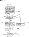
Fig. 5 is a flowchart illustrating a first control sequence of the air-conditioning apparatus 100 according to Embodiment. An operation over the network including thecontrol unit 21 and theadapter 2 will now be described with reference toFig. 5 . - The
control unit 21 receives an instruction to change details of the operation or operation mode of the air-conditioning apparatus 100. Specifically, thecontrol unit 21 receives remote control information from thecontroller 7 or test operation switch information from the test operation switch 50 (step S100). Thecontrol unit 21 allows the components (for example, the air-sending fan 106) to operate in accordance with the remote control information or the test operation switch information (step S101). - The
control unit 21 determines whether the information received in step S100 is test operation switch information or remote control information (step S102). If thecontrol unit 21 determines that the received information is test operation switch information (YES in step S102), it outputs to theadapter 2 information indicating that test operation switch information has been received (step S124). If thecontrol unit 21 determines that the received information is remote control information (NO in step S102), it outputs to theadapter 2 information indicating details of the operation currently in progress, that is, information indicating that remote control information has been received (step S114). - The
adapter 2 holds the information received from thecontrol unit 21, that is, the information indicating that test operation switch information or remote control information has been received (step S105). In step S106, the information indicating that test operation switch information or remote control information has been received is held in theadapter 2. The information indicating that test operation switch information or remote control information has been received is referred to as "adapter information A". -
Fig. 6 is a flowchart illustrating a second control sequence of the air-conditioning apparatus 100 according to Embodiment. An operation over the external network will now be described with reference toFig. 6 . - The user operates the operation terminal 9 to request information indicating how the air-
conditioning apparatus 100 is currently operating (step S200). When receiving the request from the operation terminal 9, thecentralized management device 13 determines whether the air-conditioning apparatus 100 is operating in the test operation mode (step S201). The result of determination by thecentralized management device 13 in step S201 is regularly updated in step S300, which will be described later. - If the
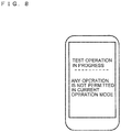
centralized management device 13 determines that the air-conditioning apparatus 100 is operating in the test operation mode (YES in step S201), it outputs to the operation terminal 9 information indicating that the air-conditioning apparatus 100 is operating in the test operation mode (step S212). In response to the received information, the operation terminal 9 displays the information indicating that the air-conditioning apparatus 100 is operating in the test operation mode (step S213).Fig. 8 illustrates an exemplary message displayed on the operation terminal 9. The operation terminal 9 performs by internal control a lock operation to prevent the operation mode of the air-conditioning apparatus 100 from being changed as the user operates the operation terminal 9 (step S214). Consequently, the air-conditioning apparatus 100 is prevented from being operated remotely from a location away from the house, thus enabling a serviceperson to more reliably check the air-conditioning apparatus 100. - If the
centralized management device 13 determines that the air-conditioning apparatus 100 is not operating in the test operation mode (NO in step S201), it outputs to the operation terminal 9 information indicating details of an operation which the air-conditioning apparatus 100 is currently performing (step S222). In response to the received information, the operation terminal 9 displays the information indicating details of the operation (step S223). The operation terminal 9 accepts an instruction to change the details of the operation of the air-conditioning apparatus 100 from the user who uses the operation terminal 9 (step S224). - The operation terminal 9 determines whether an instruction to change the details of the operation of the air-
conditioning apparatus 100 is issued (step S225). If the operation terminal 9 determines that no instruction to change the details of the operation of the air-conditioning apparatus 100 is issued (NO in step S225), the control process returns to step S200. On the other hand, if the operation terminal 9 determines that an instruction to change the details of the operation of the air-conditioning apparatus 100 is issued (YES in step S225), it transmits information indicating a change in detail of the operation to the centralized management device 13 (step S226). - The
centralized management device 13 holds the information received from the operation terminal 9. Specifically, thecentralized management device 13 holds the information indicating a change in detail of the operation output from the operation terminal 9 (step S227). In step S228, the information indicating a change in detail of the operation output from the operation terminal 9 is held in thecentralized management device 13. The information indicating a change in detail of the operation output from the operation terminal 9 will be referred to as "operation information B" hereinafter. -
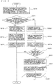
Fig. 7 is a flowchart illustrating a third control sequence of the air-conditioning apparatus 100 according to Embodiment. An operation performed by the air-conditioning system 500 will be described on the basis of the operation over the network including thecontrol unit 21 and theadapter 2, which has already been described with reference toFig. 5 , and the operation over the external network, which has already been described with reference toFig. 6 . - The
adapter 2 outputs the adapter information A held in itself to thecentralized management device 13 via therouter 8 and the Internet 12 (step S300). Thecentralized management device 13 determines whether the adapter information A output from theadapter 2 is associated with test operation switch information (step S301). If thecentralized management device 13 determines that the information is associated with test operation switch information (YES in step S301), it returns the process to step S300. - If the
centralized management device 13 determines that the adapter information A is not associated with test operation switch information (NO in step S301), it outputs the operation information B held in itself to theadapter 2 via theInternet 12 and the router 8 (step S312). Theadapter 2 outputs the received operation information B to the control unit 21 (step S313). - The
control unit 21 determines whether thetest operation switch 50 is ON (step S314). If thetest operation switch 50 is OFF (NO in step S314), thecontrol unit 21 operates various types of components (for example, the air-sending fan 106) in accordance with the operation information B designated by the user (step S315). For example, if the user has issued an instruction to increase the rate of air flow, thecontrol unit 21 increases the rate of air flow provided by the air-sendingfan 106. After that, the control process returns to step S300. - If the
test operation switch 50 is ON (YES in step S314), thecontrol unit 21 allows the air-conditioning apparatus 100 to operate in the test operation mode, regardless of the operation information B. After that, the control process returns to step S300. This is done when thecontrol unit 21 communicates with thecentralized management device 13 at a first timing, the operation information B to change the operation is output from thecentralized management device 13 to thecontrol unit 21 at a second timing, and thetest operation switch 50 is turned on in the interval between the first timing and the second timing. Specifically, although thetest operation switch 50 is OFF at the first timing (refer to steps S102 and S114 inFig. 5 ) and thecontrol unit 21 accordingly outputs the operation information B to thecontrol unit 21 at the second timing (step S313) following several steps, thetest operation switch 50 is turned on in the interval between the first timing and the second timing. - While the air-conditioning apparatus 100 (air-conditioning system 500) according to Embodiment is operating in the test operation mode, the test operation mode is maintained, regardless of a user instruction output from the operation terminal 9 via the
centralized management device 13, theInternet 12, therouter 8, and theadapter 2. Accordingly, the air-conditioning apparatus 100 (air-conditioning system 500) can suppress degradation in ease of maintenance of the air-conditioning apparatus 100 as it becomes hard for a serviceperson to check or repair the air-conditioning apparatus 100. - When the
test operation switch 50 is turned on, and a serviceperson checks the air-conditioning apparatus 100, he or she may detach a front panel (not illustrated) of theindoor unit 1 and insert his or her hands into the air-sendingfan 106 or its vicinity. The air-conditioning apparatus 100 (air-conditioning system 500) according to Embodiment can prevent such an accident that a serviceperson injures his or her hand while inserting it into the air-sendingfan 106 because in this state the air-sendingfan 106 is driven in response to an instruction from the operation terminal 9.[Reference Signs List] 1 indoor unit 1Boutdoor unit 2adapter 3 reception unit 7controller 8 router9 operation terminal 10house 11 external network 12 theInternet 13 centralized management device 13A operation restricting means 13B storage means 21 control unit 21B outdoor- unit control unit 22 information input means 23 information input-output means 24 output means 25 storage means 26 mode control means 50 test operation switch 51 expansion device 52 compressor 53 four-way valve 54 outdoor heat exchanger 55 outdoor air-sending fan 63 refrigerant pipe 100 air-conditioning apparatus 106 air-sending fan 107air vane unit 108 indoor heat exchanger 500 air-conditioning system A adapter information B operation information
Claims (4)
- An air-conditioning system (500) comprising:an air-conditioning apparatus (100) that includes an indoor unit (1) and an outdoor unit (1B);an adapter (2) connected to the indoor unit (1), the adapter (2) being configured to communicate with the indoor unit (1); anda centralized management device (13) configured to communicate with an operation terminal (9) to receive operation information (B) for operating the air-conditioning apparatus (100) from the operation terminal (9) and further communicate directly with the adapter (2) via an external network (11), characterised in that the indoor unit (1) includes a test operation switch (50) configured to perform a test operation mode in which a preset operation is executed, anda control unit (21) connected to the adapter (2), the control unit (21) being configured to perform the test operation mode when the test operation switch (50) is turned on,the control unit (21) includingmode control means (26) for, when the test operation switch (50) is turned on, transmitting information indicating that the test operation mode is performed to the centralized management device (13) via the adapter (2) and the external network (11), andthe centralized management device (13) includingoperation restricting means (13A) for, when the information indicating that the test operation mode is performed is received, restricting an operation on the operation terminal (9) to prevent an operation of the air-conditioning apparatus (100) from being changed via the operation terminal (9).
- The air-conditioning system (500) according to claim 1,
wherein the centralized management device (13) further includes
storage means (13B) for storing the operation information (B), and wherein
the operation restricting means (13A) is adapted for, when the information indicating that the test operation mode is performed is received, controlling so as not to output the operation information (B), which is sent from the operation terminal (9) and stored in the storage means (13B) to the adapter (2). - The air-conditioning system (500) of claim 1 or 2, wherein when the information indicating that the test operation mode is performed is received, the operation restricting means (13A) allows the operation terminal (9) to display information indicating that the air-conditioning apparatus (100) is operating in the test operation mode.
- The air-conditioning system (500) of any one of claims 1 to 3,
wherein when information indicating that the test operation mode is not performed is received, the operation restricting means (13A) outputs the operation information (B), received from the operation terminal (9), to the adapter (2) via the external network (11),
wherein the adapter (2) outputs the operation information (B) received from the operation restricting means (13A) to the control unit (21), and
wherein when receiving the operation information (B) from the adapter (2), the control unit (21) determines whether the test operation switch (50) is ON.
Applications Claiming Priority (1)
| Application Number | Priority Date | Filing Date | Title |
|---|---|---|---|
| JP2013186177A JP6021768B2 (en) | 2013-09-09 | 2013-09-09 | Air conditioning system |
Publications (3)
| Publication Number | Publication Date |
|---|---|
| EP2853824A2 EP2853824A2 (en) | 2015-04-01 |
| EP2853824A3 EP2853824A3 (en) | 2015-10-28 |
| EP2853824B1 true EP2853824B1 (en) | 2017-12-20 |
Family
ID=51429080
Family Applications (1)
| Application Number | Title | Priority Date | Filing Date |
|---|---|---|---|
| EP14182544.8A Active EP2853824B1 (en) | 2013-09-09 | 2014-08-27 | Air-conditioning system |
Country Status (5)
| Country | Link |
|---|---|
| US (1) | US9958179B2 (en) |
| EP (1) | EP2853824B1 (en) |
| JP (1) | JP6021768B2 (en) |
| CN (1) | CN104422089B (en) |
| AU (1) | AU2014215943B2 (en) |
Families Citing this family (5)
| Publication number | Priority date | Publication date | Assignee | Title |
|---|---|---|---|---|
| JP6270658B2 (en) * | 2014-08-06 | 2018-01-31 | 三菱電機株式会社 | Air conditioner indoor unit |
| EP3279590B1 (en) * | 2015-03-31 | 2018-12-12 | Daikin Industries, Ltd. | Air conditioner |
| CN105157176A (en) * | 2015-09-15 | 2015-12-16 | 北京爱普道尔科技有限公司 | Temperature controller conversion adapter system |
| CN109737561B (en) * | 2019-01-16 | 2021-01-22 | 奥克斯空调股份有限公司 | Intelligent air conditioner test method and air conditioner |
| JP7116338B2 (en) * | 2020-12-24 | 2022-08-10 | ダイキン工業株式会社 | Information takeover system, second substrate, air conditioner, and information takeover method |
Family Cites Families (23)
| Publication number | Priority date | Publication date | Assignee | Title |
|---|---|---|---|---|
| US5279458A (en) * | 1991-08-12 | 1994-01-18 | Carrier Corporation | Network management control |
| JP3162827B2 (en) * | 1992-09-18 | 2001-05-08 | 三洋電機株式会社 | Temperature control device |
| JPH11173625A (en) * | 1997-12-17 | 1999-07-02 | Mitsubishi Electric Corp | Air conditioner |
| JPH11182909A (en) * | 1997-12-19 | 1999-07-06 | Denso Corp | Inspection trial run device for air conditioner |
| JP2001241738A (en) * | 2000-03-02 | 2001-09-07 | Sanyo Electric Co Ltd | Refrigerator/cooler and its controlling method |
| JP2003042521A (en) * | 2001-07-26 | 2003-02-13 | Hitachi Ltd | Air conditioning apparatus |
| KR100452349B1 (en) * | 2001-10-15 | 2004-10-12 | 엘지전자 주식회사 | Air-Conditioner System and Setting Method for the Same |
| US6619055B1 (en) * | 2002-03-20 | 2003-09-16 | Honeywell International Inc. | Security system with wireless thermostat and method of operation thereof |
| EP1429082B1 (en) | 2002-12-10 | 2012-04-11 | LG Electronics Inc. | Central control system and method for controlling air conditioners |
| JP2005184711A (en) * | 2003-12-24 | 2005-07-07 | Canon Software Inc | Remote control management server, remote control management method, program and recording medium |
| KR20060059621A (en) * | 2004-11-29 | 2006-06-02 | 엘지전자 주식회사 | Apparatus for testing air conditioner |
| JP3963190B2 (en) * | 2005-04-07 | 2007-08-22 | ダイキン工業株式会社 | Refrigerant amount determination system for air conditioner |
| JP4474340B2 (en) * | 2005-07-19 | 2010-06-02 | シャープ株式会社 | Air conditioner |
| TWI318283B (en) * | 2007-07-06 | 2009-12-11 | Chunghwa Telecom Co Ltd | Network-based air-conditioning equipment remote monitoring and management system |
| JP4281836B2 (en) * | 2007-11-21 | 2009-06-17 | ダイキン工業株式会社 | Equipment for equipment, management equipment, equipment management system, equipment control method and communication control program between equipment and management equipment |
| JP2010016434A (en) * | 2008-07-01 | 2010-01-21 | Daikin Ind Ltd | Apparatus, system and method for remote management of equipment |
| JP2010034957A (en) * | 2008-07-30 | 2010-02-12 | Nippon Telegr & Teleph Corp <Ntt> | Remote control unit operating device |
| KR101622616B1 (en) * | 2009-05-15 | 2016-05-20 | 엘지전자 주식회사 | Diagnostic method for air conditioner and mobile terminal equipment using the same |
| JP2011141081A (en) | 2010-01-07 | 2011-07-21 | Mitsubishi Heavy Ind Ltd | Air-conditioning monitoring system, its control method, air conditioner, and centralized monitoring device |
| KR101294305B1 (en) * | 2011-01-21 | 2013-08-08 | 엘지전자 주식회사 | Central control system and method for setting up control points of the same |
| JP5815314B2 (en) * | 2011-07-15 | 2015-11-17 | 三菱電機ビルテクノサービス株式会社 | Terminal equipment for maintenance work |
| EP2822264B1 (en) * | 2012-02-28 | 2018-07-04 | Panasonic Corporation | Communication system, communication device, and communication method |
| EP4109005A3 (en) * | 2012-07-03 | 2023-03-08 | Samsung Electronics Co., Ltd. | Diagnosis control method for an air conditioner |
-
2013
- 2013-09-09 JP JP2013186177A patent/JP6021768B2/en active Active
-
2014
- 2014-08-12 US US14/457,318 patent/US9958179B2/en active Active
- 2014-08-19 AU AU2014215943A patent/AU2014215943B2/en active Active
- 2014-08-27 EP EP14182544.8A patent/EP2853824B1/en active Active
- 2014-09-09 CN CN201410454352.4A patent/CN104422089B/en active Active
Non-Patent Citations (1)
| Title |
|---|
| None * |
Also Published As
| Publication number | Publication date |
|---|---|
| CN104422089A (en) | 2015-03-18 |
| CN104422089B (en) | 2017-08-08 |
| EP2853824A2 (en) | 2015-04-01 |
| EP2853824A3 (en) | 2015-10-28 |
| AU2014215943A1 (en) | 2015-03-26 |
| US9958179B2 (en) | 2018-05-01 |
| AU2014215943B2 (en) | 2015-09-17 |
| US20150068234A1 (en) | 2015-03-12 |
| JP6021768B2 (en) | 2016-11-09 |
| JP2015052436A (en) | 2015-03-19 |
Similar Documents
| Publication | Publication Date | Title |
|---|---|---|
| EP2853824B1 (en) | Air-conditioning system | |
| CN107250683B (en) | Air conditioning system | |
| CN103032920B (en) | Air-conditioning, comprise the control method of the air handling system of this air-conditioning and the outdoor unit of this system | |
| JP5084502B2 (en) | Air conditioning system | |
| JP4720919B2 (en) | Compressor operation control device and air conditioner equipped with the same | |
| CN103292389B (en) | Air conditioner as well as outdoor unit and temperature controller thereof and control method of air conditioner | |
| CN109357369A (en) | Air conditioner and its refrigerant recovering control method | |
| EP3112766B1 (en) | Controller of heat source equipment | |
| CN104764159A (en) | Method of locating indoor unit by multi-split air conditioner and multi-split air conditioner | |
| KR101845563B1 (en) | A network system provided with an air conditioner and a control method the same | |
| US9464835B2 (en) | Remote software loading for refrigerant system | |
| KR100545957B1 (en) | Air conditioning apparatus and control method thereof | |
| EP1662210A1 (en) | Apparatus for monitoring air conditioner | |
| KR20090058988A (en) | Method and appliance for controlling multi-air conditioner using stand-alone type air conditioner controller | |
| KR20110020555A (en) | Air conditioner and operating method thereof | |
| KR20160010197A (en) | Air-conditioner and method | |
| JP5131185B2 (en) | Equipment control system | |
| KR20080079484A (en) | Air-conditioner system in the base station and its control method for the same | |
| JP3448440B2 (en) | Air conditioner | |
| JP2004324981A (en) | Control device for multiple room air-conditioner | |
| JP2016205687A (en) | Air conditioner | |
| KR101155346B1 (en) | Air conditioner and communication method | |
| JP6209745B2 (en) | Air conditioner | |
| JP2000205626A (en) | Air conditioner | |
| JP4333995B2 (en) | Air conditioner |
Legal Events
| Date | Code | Title | Description |
|---|---|---|---|
| PUAI | Public reference made under article 153(3) epc to a published international application that has entered the european phase |
Free format text: ORIGINAL CODE: 0009012 |
|
| 17P | Request for examination filed |
Effective date: 20140827 |
|
| AK | Designated contracting states |
Kind code of ref document: A2 Designated state(s): AL AT BE BG CH CY CZ DE DK EE ES FI FR GB GR HR HU IE IS IT LI LT LU LV MC MK MT NL NO PL PT RO RS SE SI SK SM TR |
|
| AX | Request for extension of the european patent |
Extension state: BA ME |
|
| PUAL | Search report despatched |
Free format text: ORIGINAL CODE: 0009013 |
|
| AK | Designated contracting states |
Kind code of ref document: A3 Designated state(s): AL AT BE BG CH CY CZ DE DK EE ES FI FR GB GR HR HU IE IS IT LI LT LU LV MC MK MT NL NO PL PT RO RS SE SI SK SM TR |
|
| AX | Request for extension of the european patent |
Extension state: BA ME |
|
| RIC1 | Information provided on ipc code assigned before grant |
Ipc: F24F 11/00 20060101ALI20150924BHEP Ipc: F24F 1/00 20110101AFI20150924BHEP |
|
| R17P | Request for examination filed (corrected) |
Effective date: 20160426 |
|
| RBV | Designated contracting states (corrected) |
Designated state(s): AL AT BE BG CH CY CZ DE DK EE ES FI FR GB GR HR HU IE IS IT LI LT LU LV MC MK MT NL NO PL PT RO RS SE SI SK SM TR |
|
| GRAP | Despatch of communication of intention to grant a patent |
Free format text: ORIGINAL CODE: EPIDOSNIGR1 |
|
| INTG | Intention to grant announced |
Effective date: 20170710 |
|
| GRAS | Grant fee paid |
Free format text: ORIGINAL CODE: EPIDOSNIGR3 |
|
| GRAA | (expected) grant |
Free format text: ORIGINAL CODE: 0009210 |
|
| AK | Designated contracting states |
Kind code of ref document: B1 Designated state(s): AL AT BE BG CH CY CZ DE DK EE ES FI FR GB GR HR HU IE IS IT LI LT LU LV MC MK MT NL NO PL PT RO RS SE SI SK SM TR |
|
| REG | Reference to a national code |
Ref country code: GB Ref legal event code: FG4D |
|
| REG | Reference to a national code |
Ref country code: CH Ref legal event code: EP |
|
| REG | Reference to a national code |
Ref country code: IE Ref legal event code: FG4D |
|
| REG | Reference to a national code |
Ref country code: AT Ref legal event code: REF Ref document number: 956723 Country of ref document: AT Kind code of ref document: T Effective date: 20180115 |
|
| REG | Reference to a national code |
Ref country code: DE Ref legal event code: R096 Ref document number: 602014018674 Country of ref document: DE |
|
| REG | Reference to a national code |
Ref country code: NL Ref legal event code: MP Effective date: 20171220 |
|
| PG25 | Lapsed in a contracting state [announced via postgrant information from national office to epo] |
Ref country code: FI Free format text: LAPSE BECAUSE OF FAILURE TO SUBMIT A TRANSLATION OF THE DESCRIPTION OR TO PAY THE FEE WITHIN THE PRESCRIBED TIME-LIMIT Effective date: 20171220 Ref country code: LT Free format text: LAPSE BECAUSE OF FAILURE TO SUBMIT A TRANSLATION OF THE DESCRIPTION OR TO PAY THE FEE WITHIN THE PRESCRIBED TIME-LIMIT Effective date: 20171220 Ref country code: NO Free format text: LAPSE BECAUSE OF FAILURE TO SUBMIT A TRANSLATION OF THE DESCRIPTION OR TO PAY THE FEE WITHIN THE PRESCRIBED TIME-LIMIT Effective date: 20180320 Ref country code: SE Free format text: LAPSE BECAUSE OF FAILURE TO SUBMIT A TRANSLATION OF THE DESCRIPTION OR TO PAY THE FEE WITHIN THE PRESCRIBED TIME-LIMIT Effective date: 20171220 |
|
| REG | Reference to a national code |
Ref country code: LT Ref legal event code: MG4D |
|
| REG | Reference to a national code |
Ref country code: AT Ref legal event code: MK05 Ref document number: 956723 Country of ref document: AT Kind code of ref document: T Effective date: 20171220 |
|
| PG25 | Lapsed in a contracting state [announced via postgrant information from national office to epo] |
Ref country code: BG Free format text: LAPSE BECAUSE OF FAILURE TO SUBMIT A TRANSLATION OF THE DESCRIPTION OR TO PAY THE FEE WITHIN THE PRESCRIBED TIME-LIMIT Effective date: 20180320 Ref country code: LV Free format text: LAPSE BECAUSE OF FAILURE TO SUBMIT A TRANSLATION OF THE DESCRIPTION OR TO PAY THE FEE WITHIN THE PRESCRIBED TIME-LIMIT Effective date: 20171220 Ref country code: RS Free format text: LAPSE BECAUSE OF FAILURE TO SUBMIT A TRANSLATION OF THE DESCRIPTION OR TO PAY THE FEE WITHIN THE PRESCRIBED TIME-LIMIT Effective date: 20171220 Ref country code: HR Free format text: LAPSE BECAUSE OF FAILURE TO SUBMIT A TRANSLATION OF THE DESCRIPTION OR TO PAY THE FEE WITHIN THE PRESCRIBED TIME-LIMIT Effective date: 20171220 Ref country code: GR Free format text: LAPSE BECAUSE OF FAILURE TO SUBMIT A TRANSLATION OF THE DESCRIPTION OR TO PAY THE FEE WITHIN THE PRESCRIBED TIME-LIMIT Effective date: 20180321 |
|
| PG25 | Lapsed in a contracting state [announced via postgrant information from national office to epo] |
Ref country code: NL Free format text: LAPSE BECAUSE OF FAILURE TO SUBMIT A TRANSLATION OF THE DESCRIPTION OR TO PAY THE FEE WITHIN THE PRESCRIBED TIME-LIMIT Effective date: 20171220 |
|
| PG25 | Lapsed in a contracting state [announced via postgrant information from national office to epo] |
Ref country code: CZ Free format text: LAPSE BECAUSE OF FAILURE TO SUBMIT A TRANSLATION OF THE DESCRIPTION OR TO PAY THE FEE WITHIN THE PRESCRIBED TIME-LIMIT Effective date: 20171220 Ref country code: SK Free format text: LAPSE BECAUSE OF FAILURE TO SUBMIT A TRANSLATION OF THE DESCRIPTION OR TO PAY THE FEE WITHIN THE PRESCRIBED TIME-LIMIT Effective date: 20171220 Ref country code: CY Free format text: LAPSE BECAUSE OF FAILURE TO SUBMIT A TRANSLATION OF THE DESCRIPTION OR TO PAY THE FEE WITHIN THE PRESCRIBED TIME-LIMIT Effective date: 20171220 Ref country code: EE Free format text: LAPSE BECAUSE OF FAILURE TO SUBMIT A TRANSLATION OF THE DESCRIPTION OR TO PAY THE FEE WITHIN THE PRESCRIBED TIME-LIMIT Effective date: 20171220 Ref country code: ES Free format text: LAPSE BECAUSE OF FAILURE TO SUBMIT A TRANSLATION OF THE DESCRIPTION OR TO PAY THE FEE WITHIN THE PRESCRIBED TIME-LIMIT Effective date: 20171220 |
|
| PG25 | Lapsed in a contracting state [announced via postgrant information from national office to epo] |
Ref country code: RO Free format text: LAPSE BECAUSE OF FAILURE TO SUBMIT A TRANSLATION OF THE DESCRIPTION OR TO PAY THE FEE WITHIN THE PRESCRIBED TIME-LIMIT Effective date: 20171220 Ref country code: IS Free format text: LAPSE BECAUSE OF FAILURE TO SUBMIT A TRANSLATION OF THE DESCRIPTION OR TO PAY THE FEE WITHIN THE PRESCRIBED TIME-LIMIT Effective date: 20180420 Ref country code: AT Free format text: LAPSE BECAUSE OF FAILURE TO SUBMIT A TRANSLATION OF THE DESCRIPTION OR TO PAY THE FEE WITHIN THE PRESCRIBED TIME-LIMIT Effective date: 20171220 Ref country code: SM Free format text: LAPSE BECAUSE OF FAILURE TO SUBMIT A TRANSLATION OF THE DESCRIPTION OR TO PAY THE FEE WITHIN THE PRESCRIBED TIME-LIMIT Effective date: 20171220 Ref country code: PL Free format text: LAPSE BECAUSE OF FAILURE TO SUBMIT A TRANSLATION OF THE DESCRIPTION OR TO PAY THE FEE WITHIN THE PRESCRIBED TIME-LIMIT Effective date: 20171220 |
|
| REG | Reference to a national code |
Ref country code: DE Ref legal event code: R097 Ref document number: 602014018674 Country of ref document: DE |
|
| PLBE | No opposition filed within time limit |
Free format text: ORIGINAL CODE: 0009261 |
|
| STAA | Information on the status of an ep patent application or granted ep patent |
Free format text: STATUS: NO OPPOSITION FILED WITHIN TIME LIMIT |
|
| 26N | No opposition filed |
Effective date: 20180921 |
|
| PG25 | Lapsed in a contracting state [announced via postgrant information from national office to epo] |
Ref country code: DK Free format text: LAPSE BECAUSE OF FAILURE TO SUBMIT A TRANSLATION OF THE DESCRIPTION OR TO PAY THE FEE WITHIN THE PRESCRIBED TIME-LIMIT Effective date: 20171220 |
|
| PG25 | Lapsed in a contracting state [announced via postgrant information from national office to epo] |
Ref country code: SI Free format text: LAPSE BECAUSE OF FAILURE TO SUBMIT A TRANSLATION OF THE DESCRIPTION OR TO PAY THE FEE WITHIN THE PRESCRIBED TIME-LIMIT Effective date: 20171220 |
|
| PG25 | Lapsed in a contracting state [announced via postgrant information from national office to epo] |
Ref country code: MC Free format text: LAPSE BECAUSE OF FAILURE TO SUBMIT A TRANSLATION OF THE DESCRIPTION OR TO PAY THE FEE WITHIN THE PRESCRIBED TIME-LIMIT Effective date: 20171220 |
|
| REG | Reference to a national code |
Ref country code: CH Ref legal event code: PL |
|
| GBPC | Gb: european patent ceased through non-payment of renewal fee |
Effective date: 20180827 |
|
| PG25 | Lapsed in a contracting state [announced via postgrant information from national office to epo] |
Ref country code: LI Free format text: LAPSE BECAUSE OF NON-PAYMENT OF DUE FEES Effective date: 20180831 Ref country code: LU Free format text: LAPSE BECAUSE OF NON-PAYMENT OF DUE FEES Effective date: 20180827 Ref country code: CH Free format text: LAPSE BECAUSE OF NON-PAYMENT OF DUE FEES Effective date: 20180831 |
|
| REG | Reference to a national code |
Ref country code: BE Ref legal event code: MM Effective date: 20180831 |
|
| PG25 | Lapsed in a contracting state [announced via postgrant information from national office to epo] |
Ref country code: BE Free format text: LAPSE BECAUSE OF NON-PAYMENT OF DUE FEES Effective date: 20180831 Ref country code: FR Free format text: LAPSE BECAUSE OF NON-PAYMENT OF DUE FEES Effective date: 20180831 |
|
| PG25 | Lapsed in a contracting state [announced via postgrant information from national office to epo] |
Ref country code: GB Free format text: LAPSE BECAUSE OF NON-PAYMENT OF DUE FEES Effective date: 20180827 |
|
| PG25 | Lapsed in a contracting state [announced via postgrant information from national office to epo] |
Ref country code: MT Free format text: LAPSE BECAUSE OF NON-PAYMENT OF DUE FEES Effective date: 20180827 |
|
| PG25 | Lapsed in a contracting state [announced via postgrant information from national office to epo] |
Ref country code: TR Free format text: LAPSE BECAUSE OF FAILURE TO SUBMIT A TRANSLATION OF THE DESCRIPTION OR TO PAY THE FEE WITHIN THE PRESCRIBED TIME-LIMIT Effective date: 20171220 |
|
| PG25 | Lapsed in a contracting state [announced via postgrant information from national office to epo] |
Ref country code: HU Free format text: LAPSE BECAUSE OF FAILURE TO SUBMIT A TRANSLATION OF THE DESCRIPTION OR TO PAY THE FEE WITHIN THE PRESCRIBED TIME-LIMIT; INVALID AB INITIO Effective date: 20140827 Ref country code: PT Free format text: LAPSE BECAUSE OF FAILURE TO SUBMIT A TRANSLATION OF THE DESCRIPTION OR TO PAY THE FEE WITHIN THE PRESCRIBED TIME-LIMIT Effective date: 20171220 |
|
| PG25 | Lapsed in a contracting state [announced via postgrant information from national office to epo] |
Ref country code: MK Free format text: LAPSE BECAUSE OF NON-PAYMENT OF DUE FEES Effective date: 20171220 Ref country code: IE Free format text: LAPSE BECAUSE OF NON-PAYMENT OF DUE FEES Effective date: 20180827 |
|
| PG25 | Lapsed in a contracting state [announced via postgrant information from national office to epo] |
Ref country code: AL Free format text: LAPSE BECAUSE OF FAILURE TO SUBMIT A TRANSLATION OF THE DESCRIPTION OR TO PAY THE FEE WITHIN THE PRESCRIBED TIME-LIMIT Effective date: 20171220 |
|
| REG | Reference to a national code |
Ref country code: DE Ref legal event code: R084 Ref document number: 602014018674 Country of ref document: DE |
|
| P01 | Opt-out of the competence of the unified patent court (upc) registered |
Effective date: 20230512 |
|
| PGFP | Annual fee paid to national office [announced via postgrant information from national office to epo] |
Ref country code: IT Payment date: 20230711 Year of fee payment: 10 |
|
| PGFP | Annual fee paid to national office [announced via postgrant information from national office to epo] |
Ref country code: DE Payment date: 20230703 Year of fee payment: 10 |