EP2853784A1 - Bürstendichtung für eine Turbomaschine - Google Patents
Bürstendichtung für eine Turbomaschine Download PDFInfo
- Publication number
- EP2853784A1 EP2853784A1 EP20140185094 EP14185094A EP2853784A1 EP 2853784 A1 EP2853784 A1 EP 2853784A1 EP 20140185094 EP20140185094 EP 20140185094 EP 14185094 A EP14185094 A EP 14185094A EP 2853784 A1 EP2853784 A1 EP 2853784A1
- Authority
- EP
- European Patent Office
- Prior art keywords
- spring element
- recess
- brush seal
- leg
- brush
- Prior art date
- Legal status (The legal status is an assumption and is not a legal conclusion. Google has not performed a legal analysis and makes no representation as to the accuracy of the status listed.)
- Granted
Links
- 238000007789 sealing Methods 0.000 title description 3
- 238000003780 insertion Methods 0.000 claims description 17
- 230000037431 insertion Effects 0.000 claims description 17
- 230000007704 transition Effects 0.000 claims description 8
- 238000000034 method Methods 0.000 claims description 3
- 229910000838 Al alloy Inorganic materials 0.000 claims description 2
- UQZIWOQVLUASCR-UHFFFAOYSA-N alumane;titanium Chemical compound [AlH3].[Ti] UQZIWOQVLUASCR-UHFFFAOYSA-N 0.000 claims description 2
- 210000002414 leg Anatomy 0.000 description 33
- 238000011161 development Methods 0.000 description 4
- 230000018109 developmental process Effects 0.000 description 4
- 210000003414 extremity Anatomy 0.000 description 3
- 230000006835 compression Effects 0.000 description 2
- 238000007906 compression Methods 0.000 description 2
- 230000001419 dependent effect Effects 0.000 description 2
- 239000000463 material Substances 0.000 description 2
- 229910052751 metal Inorganic materials 0.000 description 2
- 239000002184 metal Substances 0.000 description 2
- 238000010276 construction Methods 0.000 description 1
- 230000007423 decrease Effects 0.000 description 1
- 238000013461 design Methods 0.000 description 1
- 230000005489 elastic deformation Effects 0.000 description 1
- 238000009434 installation Methods 0.000 description 1
- 238000012986 modification Methods 0.000 description 1
- 230000004048 modification Effects 0.000 description 1
- 210000000689 upper leg Anatomy 0.000 description 1
- 230000003313 weakening effect Effects 0.000 description 1
- 238000003466 welding Methods 0.000 description 1
Images
Classifications
-
- F—MECHANICAL ENGINEERING; LIGHTING; HEATING; WEAPONS; BLASTING
- F01—MACHINES OR ENGINES IN GENERAL; ENGINE PLANTS IN GENERAL; STEAM ENGINES
- F01D—NON-POSITIVE DISPLACEMENT MACHINES OR ENGINES, e.g. STEAM TURBINES
- F01D11/00—Preventing or minimising internal leakage of working-fluid, e.g. between stages
- F01D11/005—Sealing means between non relatively rotating elements
-
- F—MECHANICAL ENGINEERING; LIGHTING; HEATING; WEAPONS; BLASTING
- F16—ENGINEERING ELEMENTS AND UNITS; GENERAL MEASURES FOR PRODUCING AND MAINTAINING EFFECTIVE FUNCTIONING OF MACHINES OR INSTALLATIONS; THERMAL INSULATION IN GENERAL
- F16J—PISTONS; CYLINDERS; SEALINGS
- F16J15/00—Sealings
- F16J15/16—Sealings between relatively-moving surfaces
- F16J15/32—Sealings between relatively-moving surfaces with elastic sealings, e.g. O-rings
- F16J15/3268—Mounting of sealing rings
-
- F—MECHANICAL ENGINEERING; LIGHTING; HEATING; WEAPONS; BLASTING
- F01—MACHINES OR ENGINES IN GENERAL; ENGINE PLANTS IN GENERAL; STEAM ENGINES
- F01D—NON-POSITIVE DISPLACEMENT MACHINES OR ENGINES, e.g. STEAM TURBINES
- F01D11/00—Preventing or minimising internal leakage of working-fluid, e.g. between stages
- F01D11/003—Preventing or minimising internal leakage of working-fluid, e.g. between stages by packing rings; Mechanical seals
-
- F—MECHANICAL ENGINEERING; LIGHTING; HEATING; WEAPONS; BLASTING
- F16—ENGINEERING ELEMENTS AND UNITS; GENERAL MEASURES FOR PRODUCING AND MAINTAINING EFFECTIVE FUNCTIONING OF MACHINES OR INSTALLATIONS; THERMAL INSULATION IN GENERAL
- F16J—PISTONS; CYLINDERS; SEALINGS
- F16J15/00—Sealings
- F16J15/16—Sealings between relatively-moving surfaces
- F16J15/32—Sealings between relatively-moving surfaces with elastic sealings, e.g. O-rings
- F16J15/3284—Sealings between relatively-moving surfaces with elastic sealings, e.g. O-rings characterised by their structure; Selection of materials
- F16J15/3288—Filamentary structures, e.g. brush seals
-
- F—MECHANICAL ENGINEERING; LIGHTING; HEATING; WEAPONS; BLASTING
- F05—INDEXING SCHEMES RELATING TO ENGINES OR PUMPS IN VARIOUS SUBCLASSES OF CLASSES F01-F04
- F05D—INDEXING SCHEME FOR ASPECTS RELATING TO NON-POSITIVE-DISPLACEMENT MACHINES OR ENGINES, GAS-TURBINES OR JET-PROPULSION PLANTS
- F05D2240/00—Components
- F05D2240/55—Seals
- F05D2240/56—Brush seals
-
- F—MECHANICAL ENGINEERING; LIGHTING; HEATING; WEAPONS; BLASTING
- F05—INDEXING SCHEMES RELATING TO ENGINES OR PUMPS IN VARIOUS SUBCLASSES OF CLASSES F01-F04
- F05D—INDEXING SCHEME FOR ASPECTS RELATING TO NON-POSITIVE-DISPLACEMENT MACHINES OR ENGINES, GAS-TURBINES OR JET-PROPULSION PLANTS
- F05D2260/00—Function
- F05D2260/30—Retaining components in desired mutual position
- F05D2260/38—Retaining components in desired mutual position by a spring, i.e. spring loaded or biased towards a certain position
-
- F—MECHANICAL ENGINEERING; LIGHTING; HEATING; WEAPONS; BLASTING
- F05—INDEXING SCHEMES RELATING TO ENGINES OR PUMPS IN VARIOUS SUBCLASSES OF CLASSES F01-F04
- F05D—INDEXING SCHEME FOR ASPECTS RELATING TO NON-POSITIVE-DISPLACEMENT MACHINES OR ENGINES, GAS-TURBINES OR JET-PROPULSION PLANTS
- F05D2300/00—Materials; Properties thereof
- F05D2300/10—Metals, alloys or intermetallic compounds
- F05D2300/17—Alloys
- F05D2300/174—Titanium alloys, e.g. TiAl
Definitions
- the present invention relates to a brush seal for a turbomachine, a turbomachine, in particular gas turbine, with such a brush seal and a method for assembling such a brush seal.
- a brush seal for sealing a gap between a rotor-stator assembly by means of bristles is known, which are captured by a clamping ring.
- the clamping ring or a receiving this seal housing are clamped between a shoulder of a recess of a stator housing and a separate wall, which is welded to the stator housing.
- An object of an embodiment of the present invention is to provide an improved brush seal for a turbomachine, in particular to improve its assembly and / or disassembly.
- Claims 10, 11 provide protection for a turbomachine with a corresponding brush seal or a method for mounting a corresponding brush seal.
- Advantageous embodiments of the invention are the subject of the dependent claims.
- a turbomachine in one aspect of the present invention, includes a brush seal having a carrier.
- the turbomachine may in particular be a gas turbine, preferably an aircraft engine gas turbine. It has a rotor and a housing in one embodiment.
- the brush seal can be arranged in particular in a compressor or turbine stage of the gas turbine.
- the carrier is in one embodiment a housing-fixed carrier. In particular, it can be part of the housing itself. Likewise, in one embodiment, he may use an inner cover tape a housing-fixed guide grid or with such, in particular permanently or detachably be connected.
- the carrier of a brush seal has a, preferably annular and / or axially one or both sides open, recess in which a spring element is axially braced, which in turn defines a brush element which in one embodiment, the rotor, in particular sealing, contacted.
- the brush seal can thus in particular form a radially inner air seal ("inner air seal”) of a compressor or turbine stage of a gas turbine.
- the brush element has a plurality of bristles, in particular of metal and / or plastic. In one embodiment, these can wrap around a core or can also be combined on sides facing away from the rotor, in particular connected in a material-locking manner or clamped by frictional engagement.
- the spring element is axially latched to an undercut in the recess.
- this is understood to mean, in particular in the usual manner, that the spring element in the latched state has a larger outer diameter than a radially inner edge of the undercut and is supported axially therewith on the undercut and thus braces the resiliently compressed spring element in the axial direction.
- An axial direction in the sense of the present invention can in particular be aligned with a longitudinal, in particular symmetrical or rotational axis of the brush seal or turbomachine, corresponding to a radial direction perpendicular thereto.
- the structure, assembly and / or disassembly of the brush seal can be simplified and / or their function can be improved.
- the spring element preferably elastically compressed in the radial direction, inserted into the recess and in this, in particular automatically under complete or partial elastic relaxation in the radial direction, expanded behind the undercut and there braced axially against the undercut and are thus locked axially to her.
- a separate, materially connected to the carrier wall to be omitted.
- the recess has an insertion opening for insertion, in particular in the axial direction, of the resilient element elastically compressed in the radial direction, which then expands radially relative to an insertion configuration and thus locks with the undercut and is supported on the latter.
- a circumference of the insertion opening is smaller than a (maximum) outer circumference of the spring element clamped in the recess, in particular smaller than an outer circumference of the spring element with which it is latched to the undercut.
- the undercut may be formed in one embodiment by an axial end face of a radial collar of the recess, which is preferably formed integrally with the carrier and / or defines the insertion opening.
- the recess may have a radial groove whose axial extent in a further development is at most half the axial extent of the recess and / or the spring element, and forms an axial end face of the undercut.
- the undercut may be in one embodiment, at least substantially, perpendicular to the axial direction, in particular, to support the spring element advantageous.
- a groove depth of the radial groove is in one embodiment at least twice and / or at most 20 times one, in particular maximum or minimum, wall thickness of the spring element.
- an advantageous, matched to the spring element locking can be displayed. Accordingly, in one embodiment, an outer circumference of the spring element, with which this is latched to the undercut and axially supported on the undercut, in the radial direction over a (maximum) outer circumference of the brush element before.
- the spring element is or is determined by its axial clamping in the radial direction frictionally engaged in the recess. Likewise, it may, in particular in the manner explained below, be fixed in a form-fitting manner in the recess.
- the spring element has a first leg, a second leg adjacent thereto and a third leg adjacent thereto.
- the spring element has a fourth leg adjacent to the third leg, it may thus be in particular Z- or W-shaped or have such a section.
- the brush element between the first and second legs in particular material, form and / or frictional, set, in particular clamped.
- the brush element stronger
- the first leg can be supported axially on a shoulder of the recess and so axially clamp the spring element.
- the first leg in one embodiment can also act as an axial support of the spring element and as a definition of the brush element.
- the fourth leg can be supported axially on the undercut.
- an advantageous elastic deformation characteristic can be represented.
- the fourth limb can be shortened in a development with respect to the other limbs, in particular radially above an edge delimiting the limb, in particular the insertion opening.
- the spring element can be positively supported with a transition region between the first and second legs and / or with a transition region between the third and fourth legs radially in the recess.
- the, preferably annular, brush element is integrally formed, which in particular can improve the stability.
- the multi-part brush element of several, preferably permanently or detachably connected, segments is annular, which in particular can facilitate the (de) assembly.
- The, preferably annular, spring element may also be integrally formed in one embodiment, which in particular can improve the stability.
- the multi-part spring element of several, preferably permanently or detachably connected, segments is annular, which in particular can facilitate the (de) assembly.
- the spring element has metal or is metallic. In one embodiment, the spring element, preferably galvanically coated. As a result, the contact pairing with the recess can be improved.
- the carrier is made of a titanium-aluminum alloy.
- a carrier is usually pressure-sensitive, so that the latching of the spring element according to the invention can be advantageous in particular in comparison to a screw connection, riveting or the like.
- the spring element for mounting a brush seal, the spring element, in particular under elastic radial compression, inserted into the recess and locked there under partial or complete elastic relaxation in the radial direction of the undercut, where it is supported and thereby clamped axially elastic according to one aspect of the present invention is to set the spring element in the recess.
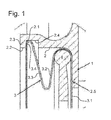
- the brush seal has a housing-fixed support 1 with an annular, axially on both sides open recess 2, in which a spring element 3 axially (horizontally in Fig. 1 ), which in turn defines a brush element 4, which sealingly contacts the rotor (not shown).
- the spring element is axially latched to an undercut 2.1 in the recess by being in the in Fig. 1 shown locked state has a larger outer diameter than a radially inner edge of the undercut and is axially supported with this on the undercut and so clamped in the axial direction elastically compressed spring element.
- the recess has an insertion opening 2.2 for insertion in the axial direction of the spring element elastically compressed in the radial direction, which subsequently expands radially relative to an insertion configuration and thus locks with the undercut and is supported on the latter. Accordingly, a circumference of the insertion opening is smaller than the outer circumference of the spring element, with which this is latched to the undercut.
- the undercut 2.1 is formed by an axial end face of a radial collar 2.3 of the recess, which is formed integrally with the carrier and defines the insertion opening.
- the recess has a radial groove 2.4, the axial extent (from left to right in Fig. 1 ) is less than half the axial extent of the recess and the spring element, and whose one axial end face forms the undercut 2.1, which is perpendicular to the axial direction.
- a groove depth of the radial groove is more than twice and less than 20 times the wall thickness of the spring element. Accordingly, the outer circumference of the spring element, with which it is latched to the undercut or axially supported on the undercut, projects in the radial direction over an outer circumference of the brush element 4.
- the spring element 3 has a first leg 3.1, a second leg 3. 2 adjacent thereto, a third leg 3. 3 adjacent thereto and a fourth leg 3. 4 adjacent to it, and is thus configured W-like.
- the brush element 4 is clamped between the first leg 3.1 and the second leg 3.2.
- the first leg 3.1 is supported axially on a shoulder 2.5 of the recess and thus braces the spring element axially.
- the fourth leg 3.4 is supported axially on the undercut 2.1 and is compared to the other legs shortened 3.1-3.3, so that it ends radially above the insertion 2.2.
- the spring element is positively supported with a transition region between the third and fourth legs radially in the radial groove 2.4 of the recess.
- the spring element is inserted under elastic radial compression in the recess and locked there under partial elastic relaxation in the radial direction of the undercut on which it is supported and thereby axially resiliently clamped to set the spring element in the recess.
- the second leg 3.2 can move in the direction of the first leg 3.1 of the spring element 3.
- the third leg 3.3 tilts more towards the axis of the turbomachine, whereby the radial extent of the transition region between the third leg 3.3 and the fourth leg 3.4 decreases.
- the transition region between the third leg 3.3 and the fourth leg 3.4 moves in FIG. 1 downward.
- it can slide in the axial direction through the insertion and then expand again by the elastic spring force in the radial direction to lock into the radial groove 2.4.
- the rounded shape of the transition region between the adjacent third leg 3.3 and fourth leg 3.4 favors the insertion of the brush seal or the spring element 3 in the recess 2.
- the substantially W-shaped design of the spring element 2 also favors the support for assembly and disassembly elastic deformability of the spring element in both the radial and in the axial direction.
- the assembly and disassembly can thus be carried out very easily, and it is not necessary to carry out the brush seal in several parts. It can rather be designed in the form of a closed ring, which is advantageous in terms of stability and installation effort. Welding, screwing, riveting or the like is not necessary for the assembly of the brush element. Nevertheless, a secure hold of the brush seal in the carrier 1 is ensured.
Landscapes
- Engineering & Computer Science (AREA)
- General Engineering & Computer Science (AREA)
- Mechanical Engineering (AREA)
- Sealing Devices (AREA)
Abstract
Description
- Die vorliegende Erfindung betrifft eine Bürstendichtung für eine Turbomaschine, eine Turbomaschine, insbesondere Gasturbine, mit einer solchen Bürstendichtung sowie ein Verfahren zur Montage einer solchen Bürstendichtung.
- Aus der
DE 296 00 193 U1 ist eine Bürstendichtung zur Abdichtung eines Spaltes zwischen einer Rotor-Stator-Anordnung mittels Borsten bekannt, die durch einen Klemmring gefasst sind. Der Klemmring oder ein dieses aufnehmendes Dichtungsgehäuse sind zwischen einer Schulter einer Aussparung eines Statorgehäuses und einer separaten Wand verklemmt, die mit dem Statorgehäuse verschweißt ist. - Eine Aufgabe einer Ausführung der vorliegenden Erfindung ist es, eine verbesserte Bürstendichtung für eine Turbomaschine zur Verfügung zu stellen, insbesondere deren Montage und/oder Demontage zu verbessern.
- Diese Aufgabe wird durch eine Bürstendichtung mit den Merkmalen des Anspruchs 1 gelöst. Ansprüche 10, 11 stellen eine Turbomaschine mit einer entsprechenden Bürstendichtung bzw. ein Verfahren zur Montage einer entsprechenden Bürstendichtung unter Schutz. Vorteilhafte Ausführungsformen der Erfindung sind Gegenstand der Unteransprüche.
- Nach einem Aspekt der vorliegenden Erfindung weist eine Turbomaschine eine Bürstendichtung mit einem Träger auf.
- Die Turbomaschine kann insbesondere eine Gasturbine, vorzugsweise eine Flugtriebwerksgasturbine, sein. Sie weist in einer Ausführung einen Rotor und ein Gehäuse auf. Die Bürstendichtung kann insbesondere in einer Verdichter- oder Turbinenstufe der Gasturbine angeordnet sein.
- Der Träger ist in einer Ausführung ein gehäusefester Träger. Er kann insbesondere Teil des Gehäuses selber sein. Gleichermaßen kann er in einer Ausführung ein Innendeckband eines gehäusefesten Leitgitters oder mit einem solchen, insbesondere dauerhaft oder lösbar, verbunden sein.
- Der Träger einer erfindungsgemäßen Bürstendichtung weist eine, vorzugsweise ringartige und/oder axial ein- oder beidseitig offene, Aussparung auf, in der ein Federelement axial verspannt ist, welches seinerseits ein Bürstenelement festlegt, das in einer Ausführung den Rotor, insbesondere dichtend, kontaktiert. Die Bürstendichtung kann somit insbesondere eine radial innere Luftdichtung ("Inner Air Seal") einer Verdichter- oder Turbinenstufe einer Gasturbine bilden.
- Das Bürstenelement weist in einer Ausführung mehrere Borsten, insbesondere aus Metall und/oder Kunststoff, auf. Diese können in einer Ausführung einen Kern umschlingen oder auch an rotorabgewandten Seiten zusammengefasst, insbesondere stoffschlüssig verbunden oder reibschlüssig geklemmt sein.
- Nach einem Aspekt der vorliegenden Erfindung ist das Federelement an einer Hinterschneidung in der Aussparung axial verrastet. Hierunter wird vorliegend insbesondere in fachüblicher Weise verstanden, dass das Federelement im verrasteten Zustand einen größeren Außendurchmesser als eine radial innere Kante der Hinterschneidung aufweist und sich mit diesem axial an der Hinterschneidung abstützt und so das in axialer Richtung elastisch komprimierte Federelement verspannt. Eine axiale Richtung im Sinne der vorliegenden Erfindung kann insbesondere mit einer Längs-, insbesondere Symmetrie- bzw. Rotationsachse der Bürstendichtung bzw. Turbomaschine fluchten, eine radiale Richtung entsprechend senkrecht hierzu orientiert sein.
- Indem das Federelement an der Hinterscheidung in axialer Richtung verrastet ist und sich an dieser axial abstützt, kann in einer Ausführung die Struktur, die Montage und/oder Demontage der Bürstendichtung vereinfacht und/oder ihre Funktion verbessert werden. Insbesondere kann in einer Ausführung das Federelement, vorzugsweise elastisch in radialer Richtung komprimiert, in die Aussparung eingeführt und in dieser, insbesondere selbsttätig unter vollständiger oder teilweiser elastischer Entspannung in radialer Richtung, hinter der Hinterschneidung expandiert und dort gegen die Hinterschneidung axial verspannt und so axial an ihr verrastet werden. Somit kann in einer vorteilhaften Ausführung eine separate, stoffschlüssig mit dem Träger zu verbindende Wand entfallen.
- In einer Ausführung weist die Aussparung eine Einführöffnung zum Einführen, insbesondere in axialer Richtung, des hierzu in radialer Richtung elastisch komprimierten Federelements auf, welches anschließend gegenüber einer Einführkonfiguration radial expandiert und so mit der Hinterschneidung verrastet und sich an dieser abstützt. Entsprechend ist ein Umfang der Einführöffnung in einer Ausführung kleiner als ein (maximaler) Außenumfang des in der Aussparung verspannten Federelements, insbesondere kleiner als ein Außenumfang des Federelements, mit dem dieses an der Hinterschneidung verrastet ist.
- Die Hinterschneidung kann in einer Ausführung durch eine axiale Stirnseite eines Radialbunds der Aussparung gebildet sein, der vorzugsweise einstückig mit dem Träger ausgebildet ist und/oder die Einführöffnung definiert. Insbesondere kann die Aussparung eine Radialnut aufweisen, deren axiale Erstreckung in einer Weiterbildung höchstens die Hälfte der axialen Erstreckung der Aussparung und/oder des Federelements beträgt, und deren eine axiale Stirnseite die Hinterschneidung bildet. Insbesondere durch eine solche, im Verhältnis zur Aussparung bzw. dem Federelement schmalen Radialnut kann eine vorteilhafte Verrastung bei geringer Materialschwächung dargestellt werden. Die Hinterschneidung kann in einer Ausführung, wenigstens im Wesentlichen, senkrecht zur axialen Richtung sein, insbesondere, um das Federelement vorteilhaft abzustützen. Eine Nuttiefe der Radialnut beträgt in einer Ausführung wenigstens das Doppelte und/oder höchstens das 20fache einer, insbesondere maximalen oder minimalen, Wandstärke des Federelements. Hierdurch kann in einer Ausführung eine vorteilhafte, auf das Federelement abgestimmte Verrastung dargestellt werden. Entsprechend steht in einer Ausführung ein Außenumfang des Federelements, mit dem dieses an der Hinterschneidung verrastet ist bzw. sich axial an der Hinterschneidung abstützt, in radialer Richtung über einen (maximalen) Außenumfang des Bürstenelements vor.
- In einer Ausführung ist bzw. wird das Federelement durch seine axiale Verspannung auch in radialer Richtung reibschlüssig in der Aussparung festgelegt. Gleichermaßen kann es, insbesondere in nachfolgend erläuterter Weise, formschlüssig in der Aussparung festgelegt sein.
- In einer Ausführung weist das Federelement einen ersten Schenkel, einen diesem benachbarten zweiten Schenkel und einen diesem benachbarten dritten Schenkel auf. In einer Weiterbildung weist das Federelement einen dem dritten Schenkel benachbarten vierten Schenkel auf, es kann somit insbesondere Z- oder W-artig ausgebildet sein bzw. einen solchen Abschnitt aufweisen.
- In einer Ausführung ist das Bürstenelement zwischen dem ersten und zweiten Schenkel, insbesondere stoff-, form- und/oder reibschlüssig, festgelegt, insbesondere geklemmt. So kann in einer Ausführung durch die axiale Verspannung des Federelements zugleich auch das Bürstenelement (stärker) festgelegt werden.
- Zusätzlich oder alternativ kann der erste Schenkel sich axial an einer Schulter der Aussparung abstützen und so das Federelement axial verspannen. Auf diese Weise kann der erste Schenkel in einer Ausführung zugleich als axiale Abstützung des Federelements und als Festlegung des Bürstenelements fungieren.
- Zusätzlich oder alternativ kann der vierte Schenkel sich axial an der Hinterschneidung abstützen. Auf diese Weise kann, insbesondere durch ein W-artiges Federelement, eine vorteilhafte elastische Deformationscharakteristik dargestellt werden. Der vierte Schenkel kann in einer Weiterbildung gegenüber den anderen Schenkeln verkürzt sein, insbesondere radial oberhalb einer die Hinterscheidung begrenzenden Kante, insbesondere der Einführöffnung, enden.
- In einer Ausführung kann das Federelement sich formschlüssig mit einem Übergangsbereich zwischen dem ersten und zweiten Schenkel und/oder mit einem Übergangsbereich zwischen dem dritten und vierten Schenkel radial in der Aussparung abstützen.
- In einer Ausführung ist das, vorzugsweise ringförmige, Bürstenelement einteilig ausgebildet, was insbesondere die Stabilität verbessern kann. In einer anderen Ausführung ist das mehrteilige Bürstenelement aus mehreren, vorzugsweise dauerhaft oder lösbar verbundenen, Segmenten ringförmig zusammengesetzt, was insbesondere die (De)Montage erleichtern kann.
- Das, vorzugsweise ringförmige, Federelement kann in einer Ausführung ebenfalls einteilig ausgebildet sein, was insbesondere die Stabilität verbessern kann. In einer anderen Ausführung ist das mehrteilige Federelement aus mehreren, vorzugsweise dauerhaft oder lösbar verbundenen, Segmenten ringförmig zusammengesetzt, was insbesondere die (De)Montage erleichtern kann.
- Das Federelement weist in einer Ausführung Metall auf bzw. ist metallisch ausgebildet. In einer Ausführung ist das Federelement, vorzugsweise galvanisch, beschichtet. Hierdurch kann die Kontaktpaarung mit der Aussparung verbessert werden.
- In einer Ausführung ist der Träger aus einer Titan-Aluminium-Legierung hergestellt. Ein solcher Träger ist üblicherweise druckempfindlich, so dass die erfindungsgemäße Verrastung des Federelements insbesondere gegenüber einer Verschraubung, Vernietung oder dergleichen vorteilhaft sein kann.
- Zur Montage einer Bürstendichtung wird nach einem Aspekt der vorliegenden Erfindung das Federelement, insbesondere unter elastischer radialer Kompression, in die Aussparung eingeführt und verrastet dort unter teilweiser oder vollständiger elastischer Entspannung in radialer Richtung an der Hinterschneidung, an der es sich abstützt und hierdurch axial elastisch verspannt ist, um das Federelement in der Aussparung festzulegen.
- Weitere vorteilhafte Weiterbildungen der vorliegenden Erfindung ergeben sich aus den Unteransprüchen und der nachfolgenden Beschreibung bevorzugter Ausführungen. Hierzu zeigt, teilweise schematisiert, die einzige:
-
Fig. 1 einen Teil einer Bürstendichtung einer Gasturbine nach einer Ausführung der vorliegenden Erfindung in einem Meridianschnitt. -
Fig. 1 zeigt einen Teil einer Bürstendichtung einer Gasturbine mit einem Rotor und einem Gehäuse (nicht dargestellt) nach einer Ausführung der vorliegenden Erfindung in einem Meridianschnitt. - Die Bürstendichtung weist einen gehäusefesten Träger 1 mit einer ringartigen, axial beidseitig offenen Aussparung 2 auf, in der ein Federelement 3 axial (horizontal in
Fig. 1 ) verspannt ist, welches seinerseits ein Bürstenelement 4 festlegt, das den Rotor dichtend kontaktiert (nicht dargestellt). - Das Federelement ist an einer Hinterschneidung 2.1 in der Aussparung axial verrastet, indem es im in
Fig. 1 dargestellten verrasteten Zustand einen größeren Außendurchmesser als eine radial innere Kante der Hinterschneidung aufweist und sich mit diesem axial an der Hinterschneidung abstützt und so das in axialer Richtung elastisch komprimierte Federelement verspannt. - Die Aussparung weist eine Einführöffnung 2.2 zum Einführen in axialer Richtung, des hierzu in radialer Richtung elastisch komprimierten Federelements auf, welches anschließend gegenüber einer Einführkonfiguration radial expandiert und so mit der Hinterschneidung verrastet und sich an dieser abstützt. Entsprechend ist ein Umfang der Einführöffnung kleiner als der Außenumfang des Federelements, mit dem dieses an der Hinterschneidung verrastet ist.
- Die Hinterschneidung 2.1 ist durch eine axiale Stirnseite eines Radialbunds 2.3 der Aussparung gebildet, der einstückig mit dem Träger ausgebildet ist und die Einführöffnung definiert. Hierzu weist die Aussparung eine Radialnut 2.4 auf, deren axiale Erstreckung (von links nach rechts in
Fig. 1 ) weniger als die Hälfte der axialen Erstreckung der Aussparung und des Federelements beträgt, und deren eine axiale Stirnseite die Hinterschneidung 2.1 bildet, die senkrecht zur axialen Richtung ist. Eine Nuttiefe der Radialnut beträgt mehr als das Doppelte und weniger als das 20fache der Wandstärke des Federelements. Entsprechend steht der Außenumfang des Federelements, mit dem dieses an der Hinterschneidung verrastet ist bzw. sich axial an der Hinterschneidung abstützt, in radialer Richtung über einen Außenumfang des Bürstenelements 4 vor. - Das Federelement 3 weist einen ersten Schenkel 3.1, einen diesem benachbarten zweiten Schenkel 3.2, einen diesem benachbarten dritten Schenkel 3.3 und einen diesem benachbarten vierten Schenkel 3.4 auf und ist somit W-artig ausgebildet.
- Das Bürstenelement 4 ist zwischen dem ersten Schenkel 3.1 und dem zweiten Schenkel 3.2 geklemmt.
- Der erste Schenkel 3.1 stützt sich axial an einer Schulter 2.5 der Aussparung ab und verspannt so das Federelement axial.
- Der vierte Schenkel 3.4 stützt sich axial an der Hinterschneidung 2.1 ab und ist gegenüber den anderen Schenkeln 3.1-3.3 verkürzt, so dass er radial oberhalb der Einführöffnung 2.2 endet.
- Das Federelement stützt sich formschlüssig mit einem Übergangsbereich zwischen dem dritten und vierten Schenkel radial in der Radialnut 2.4 der Aussparung ab.
- Zur Montage der Bürstendichtung wird das Federelement unter elastischer radialer Kompression in die Aussparung eingeführt und verrastet dort unter teilweiser elastischer Entspannung in radialer Richtung an der Hinterschneidung, an der es sich abstützt und hierdurch axial elastisch verspannt ist, um das Federelement in der Aussparung festzulegen.
- Insbesondere kann sich bei der Montage der Bürstendichtung unter Aufbringung einer Druckkraft der zweite Schenkel 3.2 in Richtung auf den ersten Schenkel 3.1 des Federelements 3 hin bewegen. Hierdurch neigt sich der dritte Schenkel 3.3 stärker zu der Achse der Turbomaschine hin, wodurch sich die radiale Erstreckung des Übergangsbereichs zwischen dem dritten Schenkel 3.3 und dem vierten Schenkel 3.4 verkleinert. Mit anderen Worten wandert der Übergangsbereich zwischen dem dritten Schenkel 3.3 und dem vierten Schenkel 3.4 in
Figur 1 nach unten. Somit kann er in axialer Richtung durch die Einführöffnung gleiten und sich danach durch die elastische Federkraft wieder in radial Richtung ausdehnen, um in die Radialnut 2.4 einzurasten. Die abgerundete Form des Übergangsbereichs zwischen den benachbarten dritten Schenkel 3.3 und vierten Schenkel 3.4 begünstigt dabei das Einführen der Bürstendichtung bzw. des Federelements 3 in die Aussparung 2. Die im Wesentlichen W-förmige Ausbildung des Federelements 2 begünstigt zudem die zur Montage bzw. Demontage unterstützende elastische Verformbarkeit des Federelements sowohl in radialer als auch in axialer Richtung. Die Montage bzw. Demontage kann somit sehr einfach durchgeführt werden, wobei es nicht notwendig ist, die Bürstendichtung mehrteilig auszuführen. Sie kann vielmehr in Form eines geschlossenen Rings ausgeführt sein, was vorteilhaft im Hinblick auf die Stabilität und des Montageaufwandes ist. Ein Verschweißen, Verschrauben, Vernieten oder dergleichen ist für die Montage des Bürstenelements nicht notwendig. Gleichwohl wird ein sicherer Halt der Bürstendichtung im Träger 1 gewährleistet. - Obwohl in der vorhergehenden Beschreibung exemplarische Ausführungen erläutert wurden, sei darauf hingewiesen, dass eine Vielzahl von Abwandlungen möglich ist. Außerdem sei darauf hingewiesen, dass es sich bei den exemplarischen Ausführungen lediglich um Beispiele handelt, die den Schutzbereich, die Anwendungen und den Aufbau in keiner Weise einschränken sollen. Vielmehr wird dem Fachmann durch die vorausgehende Beschreibung ein Leitfaden für die Umsetzung von mindestens einer exemplarischen Ausführung gegeben, wobei diverse Änderungen, insbesondere in Hinblick auf die Funktion und Anordnung der beschriebenen Bestandteile, vorgenommen werden können, ohne den Schutzbereich zu verlassen, wie er sich aus den Ansprüchen und diesen äquivalenten Merkmalskombinationen ergibt.
-
- 1
- Träger
- 2
- Aussparung
- 2.1
- Hinterschneidung
- 2.2
- Einführöffnung
- 2.3
- Radialbund
- 2.4
- Radialnut
- 2.5
- Schulter
- 3
- Federelement
- 3.1
- erster Schenkel
- 3.2
- zweiter Schenkel
- 3.3
- dritter Schenkel
- 3.4
- vierter Schenkel
- 4
- Bürstenelement
Claims (11)
- Bürstendichtung für eine Turbomaschine, mit einem Träger (1), der eine Aussparung (2) aufweist, in der ein Federelement (3) axial verspannt ist, welches ein Bürstenelement (4) festlegt;
dadurch gekennzeichnet, dass
das Federelement an einer Hinterschneidung (2.1) in der Aussparung axial verrastet ist. - Bürstendichtung nach dem vorhergehenden Anspruch, dadurch gekennzeichnet, dass das Federelement radial reib- und/oder formschlüssig in der Aussparung festgelegt ist.
- Bürstendichtung nach einem der vorhergehenden Ansprüche, dadurch gekennzeichnet, dass die Aussparung eine Einführöffnung (2.2) zum Einführen des anschließend radial expandierten Federelements aufweist.
- Bürstendichtung nach einem der vorhergehenden Ansprüche, dadurch gekennzeichnet, dass das Federelement einen ersten Schenkel (3.1), einen diesem benachbarten zweiten Schenkel (3.2) und einen diesem benachbarten dritten Schenkel (3.3) aufweist, wobei das Bürstenelement zwischen dem ersten und zweiten Schenkel festlegt, insbesondere geklemmt ist, und/oder das Federelement einen dem dritten Schenkel benachbarten vierten Schenkel (3.4) aufweist, der sich an der Hinterschneidung abstützt.
- Bürstendichtung nach dem vorhergehenden Anspruch, dadurch gekennzeichnet, dass der erste Schenkel sich axial an einer Schulter (2.5) der Aussparung abstützt.
- Bürstendichtung nach einem der beiden vorhergehenden Ansprüche, dadurch gekennzeichnet, dass das Federelement sich radial mit einem Übergangsbereich zwischen dem ersten und zweiten Schenkel und/oder mit einem Übergangsbereich zwischen dem dritten und vierten Schenkel in der Aussparung abstützt.
- Bürstendichtung nach einem der vorhergehenden Ansprüche, dadurch gekennzeichnet, dass das ringförmige Bürsten- und/oder Federelement ein- oder mehrteilig ausgebildet ist.
- Bürstendichtung nach einem der vorhergehenden Ansprüche, dadurch gekennzeichnet, dass das, insbesondere metallische, Federelement, insbesondere galvanisch, beschichtet ist.
- Bürstendichtung nach einem der vorhergehenden Ansprüche, dadurch gekennzeichnet, dass der Träger aus einer Titan-Aluminium-Legierung hergestellt ist.
- Turbomaschine, insbesondere Gasturbine, mit einem Rotor, einem Gehäuse und einer Bürstendichtung nach einem der vorhergehenden Ansprüche mit einem gehäusefesten Träger, der die Aussparung aufweist, wobei das Bürstenelement den Rotor kontaktiert.
- Verfahren zur Montage einer Bürstendichtung nach einem der vorhergehenden Ansprüche, mit den Schritten:Einführen des Federelements in die Aussparung; undVerrasten des Federelements an der Hinterschneidung.
Applications Claiming Priority (1)
| Application Number | Priority Date | Filing Date | Title |
|---|---|---|---|
| DE201310219832 DE102013219832B3 (de) | 2013-09-30 | 2013-09-30 | Bürstendichtung für eine Turbomaschine |
Publications (2)
| Publication Number | Publication Date |
|---|---|
| EP2853784A1 true EP2853784A1 (de) | 2015-04-01 |
| EP2853784B1 EP2853784B1 (de) | 2017-06-28 |
Family
ID=51584958
Family Applications (1)
| Application Number | Title | Priority Date | Filing Date |
|---|---|---|---|
| EP14185094.1A Not-in-force EP2853784B1 (de) | 2013-09-30 | 2014-09-17 | Bürstendichtung für eine Turbomaschine |
Country Status (3)
| Country | Link |
|---|---|
| US (1) | US10240472B2 (de) |
| EP (1) | EP2853784B1 (de) |
| DE (1) | DE102013219832B3 (de) |
Families Citing this family (5)
| Publication number | Priority date | Publication date | Assignee | Title |
|---|---|---|---|---|
| DE102013205922B4 (de) * | 2013-04-04 | 2016-09-29 | MTU Aero Engines AG | Vorrichtung und Verfahren zur Befestigung von Dichtungselementen |
| DE102016209549A1 (de) * | 2016-06-01 | 2017-12-07 | Voith Patent Gmbh | Stirnradgetriebe |
| US11028712B2 (en) | 2019-03-27 | 2021-06-08 | Raytheon Technologies Corporation | Seal support feature for brush seals |
| CN112502786A (zh) * | 2020-09-23 | 2021-03-16 | 中国航发沈阳发动机研究所 | 一种刷式密封结构及其加工方法 |
| US12449039B1 (en) | 2024-07-11 | 2025-10-21 | Rtx Corporation | Brush seal assembly with metal cover |
Citations (4)
| Publication number | Priority date | Publication date | Assignee | Title |
|---|---|---|---|---|
| GB2188121A (en) * | 1986-03-21 | 1987-09-23 | Rolls Royce | Retaining rings |
| DE29600193U1 (de) | 1996-01-08 | 1996-03-14 | MTU Motoren- und Turbinen-Union München GmbH, 80995 München | Bürstendichtung mit C-förmigem Klemmring |
| US20050151324A1 (en) * | 2004-01-12 | 2005-07-14 | Snecma Moteurs | Sealing device for a high-pressure turbine of a turbomachine |
| EP2626601A1 (de) * | 2012-02-10 | 2013-08-14 | Siemens Aktiengesellschaft | Dichtungsanordnung für eine Turbomaschine |
Family Cites Families (19)
| Publication number | Priority date | Publication date | Assignee | Title |
|---|---|---|---|---|
| DE3003470C2 (de) * | 1980-01-31 | 1982-02-25 | MTU Motoren- und Turbinen-Union München GmbH, 8000 München | Turbinenleitschaufelaufhängung für Gasturbinenstrahltriebwerke |
| FR2596115A1 (fr) * | 1986-03-21 | 1987-09-25 | Rolls Royce | Perfectionnement aux moyens de retenue |
| US4957301A (en) * | 1989-10-02 | 1990-09-18 | Whiting Roll-Up Door Mfg. Corp. | Non-crushable side seal members for a roll-up door |
| US5076590A (en) * | 1990-11-26 | 1991-12-31 | The United States Of America, As Represented By The Administrator Of The National Aeronautics And Space Administration | High temperature, flexible pressure-actuated, brush seal |
| US5400586A (en) * | 1992-07-28 | 1995-03-28 | General Electric Co. | Self-accommodating brush seal for gas turbine combustor |
| US5265412A (en) * | 1992-07-28 | 1993-11-30 | General Electric Company | Self-accommodating brush seal for gas turbine combustor |
| US5749584A (en) * | 1992-11-19 | 1998-05-12 | General Electric Company | Combined brush seal and labyrinth seal segment for rotary machines |
| US7181843B1 (en) * | 1995-09-28 | 2007-02-27 | United Technologies Corporation | Method of manufacturing a brush seal |
| US5639211A (en) * | 1995-11-30 | 1997-06-17 | United Technology Corporation | Brush seal for stator of a gas turbine engine case |
| DE19618475B4 (de) * | 1996-05-08 | 2005-10-20 | Mtu Aero Engines Gmbh | Bürstendichtung |
| DE10018273B4 (de) * | 2000-04-13 | 2005-10-20 | Mtu Aero Engines Gmbh | Bürstendichtung |
| US6913265B2 (en) * | 2000-08-09 | 2005-07-05 | Advanced Components & Materials, Inc. | Brush seal assembly, method of manufacture and use |
| US6547257B2 (en) * | 2001-05-04 | 2003-04-15 | General Electric Company | Combination transition piece floating cloth seal and stage 1 turbine nozzle flexible sealing element |
| DE10163804B4 (de) * | 2001-12-22 | 2005-07-07 | Mtu Aero Engines Gmbh | Bürstendichtung |
| GB0201666D0 (en) * | 2002-01-25 | 2002-03-13 | Cross Mfg 1938 Company Ltd | A brush seal element |
| GB0308147D0 (en) * | 2003-04-09 | 2003-05-14 | Rolls Royce Plc | A seal |
| GB2407626A (en) * | 2003-10-31 | 2005-05-04 | Rolls Royce Plc | Suspended seal arrangement |
| US7419164B2 (en) * | 2006-08-15 | 2008-09-02 | General Electric Company | Compliant plate seals for turbomachinery |
| JP5118552B2 (ja) * | 2008-05-20 | 2013-01-16 | 三菱重工業株式会社 | 回転機械の軸シール装置 |
-
2013
- 2013-09-30 DE DE201310219832 patent/DE102013219832B3/de not_active Expired - Fee Related
-
2014
- 2014-09-17 EP EP14185094.1A patent/EP2853784B1/de not_active Not-in-force
- 2014-09-25 US US14/496,564 patent/US10240472B2/en not_active Expired - Fee Related
Patent Citations (4)
| Publication number | Priority date | Publication date | Assignee | Title |
|---|---|---|---|---|
| GB2188121A (en) * | 1986-03-21 | 1987-09-23 | Rolls Royce | Retaining rings |
| DE29600193U1 (de) | 1996-01-08 | 1996-03-14 | MTU Motoren- und Turbinen-Union München GmbH, 80995 München | Bürstendichtung mit C-förmigem Klemmring |
| US20050151324A1 (en) * | 2004-01-12 | 2005-07-14 | Snecma Moteurs | Sealing device for a high-pressure turbine of a turbomachine |
| EP2626601A1 (de) * | 2012-02-10 | 2013-08-14 | Siemens Aktiengesellschaft | Dichtungsanordnung für eine Turbomaschine |
Also Published As
| Publication number | Publication date |
|---|---|
| US10240472B2 (en) | 2019-03-26 |
| US20150093235A1 (en) | 2015-04-02 |
| DE102013219832B3 (de) | 2015-03-12 |
| EP2853784B1 (de) | 2017-06-28 |
Similar Documents
| Publication | Publication Date | Title |
|---|---|---|
| DE102014223231B4 (de) | Turbomaschinenschaufelanordnung | |
| EP2806107B1 (de) | Geteilter Innenring | |
| DE10018273A1 (de) | Bürstendichtung | |
| EP2853784B1 (de) | Bürstendichtung für eine Turbomaschine | |
| EP2846002A1 (de) | Gasturbine | |
| DE112014004381T5 (de) | Fixierung eines Rotors einer elektronisch gesteuerten Turbomaschine | |
| DE102014114695A1 (de) | Verriegelnde Abstandshalteranordnung | |
| EP2719865A1 (de) | Einlage für Schaufel-Scheiben-Verbindungen von Strömungsmaschinen | |
| EP2799776A1 (de) | Brennerdichtung für Gasturbinen-Brennkammerkopf und Hitzeschild | |
| EP3181918B1 (de) | Befestigungsanordnung | |
| EP2960555A1 (de) | Bürstendichtungssystem zum abdichten eines spalts zwischen relativ zueinander bewegbaren bauteilen einer strömungsmaschine | |
| WO2009007165A1 (de) | Ladeluftschlauch | |
| DE102016205997A1 (de) | Leitschaufelsegment | |
| DE102019124640A1 (de) | Schaufelblattummantelungsanordnung unter verwendung eines zapfens mit einem aussengewindebolzen und einer mutter | |
| DE102016215807A1 (de) | Innenring für einen Leitschaufelkranz einer Strömungsmaschine | |
| DE60318852T2 (de) | Apparat und Methode zur Dämpfung von Vibrationen zwischen Kompressorleitschaufeln und dem Gehäuse einer Gasturbine | |
| DE102005058161B4 (de) | Schnellverschluss für den Installationsbereich | |
| EP3477048A1 (de) | Kombination zum abdichten eines spalts zwischen turbomaschinenschaufeln und zum reduzieren von schwingungen der turbomaschinenschaufeln | |
| DE2609702C1 (de) | Duesenleitschaufel fuer ein Gasturbinentriebwerk | |
| DE102013205948B4 (de) | Sicherungssystem und Verfahren zur Sicherung eines Befestigungsbereichs wenigstens einer Rotorschaufel oder eines Rotorschaufelsegments in einem Montagebereich eines Rotorgrundkörpers | |
| DE102014114993A1 (de) | Verfahren und System zur Schaffung einer Abdichtung in Gasturbinen | |
| DE102015201401B4 (de) | Vorrichtung und Verfahren zur Befestigung von Dichtungselementen | |
| DE102019210753A1 (de) | Integral beschaufelter Turbomaschinen Rotor | |
| EP2725202A1 (de) | Innenring-Dichtungsträgeranordnung eines verstellbaren Leitschaufelgitters einer Strömungsmaschine | |
| DE102016225604B4 (de) | Dichtungsanordnung, Rotor mit einer solchen Dichtungsanordnung und Gasturbine mit einem solchen Rotor |
Legal Events
| Date | Code | Title | Description |
|---|---|---|---|
| PUAI | Public reference made under article 153(3) epc to a published international application that has entered the european phase |
Free format text: ORIGINAL CODE: 0009012 |
|
| 17P | Request for examination filed |
Effective date: 20140917 |
|
| AK | Designated contracting states |
Kind code of ref document: A1 Designated state(s): AL AT BE BG CH CY CZ DE DK EE ES FI FR GB GR HR HU IE IS IT LI LT LU LV MC MK MT NL NO PL PT RO RS SE SI SK SM TR |
|
| AX | Request for extension of the european patent |
Extension state: BA ME |
|
| R17P | Request for examination filed (corrected) |
Effective date: 20150930 |
|
| RBV | Designated contracting states (corrected) |
Designated state(s): AL AT BE BG CH CY CZ DE DK EE ES FI FR GB GR HR HU IE IS IT LI LT LU LV MC MK MT NL NO PL PT RO RS SE SI SK SM TR |
|
| REG | Reference to a national code |
Ref country code: DE Ref legal event code: R079 Ref document number: 502014004395 Country of ref document: DE Free format text: PREVIOUS MAIN CLASS: F16J0015320000 Ipc: F16J0015328800 |
|
| RIC1 | Information provided on ipc code assigned before grant |
Ipc: F16J 15/3268 20160101ALI20161213BHEP Ipc: F01D 11/00 20060101ALI20161213BHEP Ipc: F16J 15/3288 20160101AFI20161213BHEP |
|
| GRAP | Despatch of communication of intention to grant a patent |
Free format text: ORIGINAL CODE: EPIDOSNIGR1 |
|
| INTG | Intention to grant announced |
Effective date: 20170303 |
|
| GRAS | Grant fee paid |
Free format text: ORIGINAL CODE: EPIDOSNIGR3 |
|
| GRAA | (expected) grant |
Free format text: ORIGINAL CODE: 0009210 |
|
| AK | Designated contracting states |
Kind code of ref document: B1 Designated state(s): AL AT BE BG CH CY CZ DE DK EE ES FI FR GB GR HR HU IE IS IT LI LT LU LV MC MK MT NL NO PL PT RO RS SE SI SK SM TR |
|
| REG | Reference to a national code |
Ref country code: GB Ref legal event code: FG4D Free format text: NOT ENGLISH |
|
| REG | Reference to a national code |
Ref country code: CH Ref legal event code: EP |
|
| REG | Reference to a national code |
Ref country code: AT Ref legal event code: REF Ref document number: 905163 Country of ref document: AT Kind code of ref document: T Effective date: 20170715 |
|
| REG | Reference to a national code |
Ref country code: IE Ref legal event code: FG4D Free format text: LANGUAGE OF EP DOCUMENT: GERMAN |
|
| REG | Reference to a national code |
Ref country code: DE Ref legal event code: R096 Ref document number: 502014004395 Country of ref document: DE |
|
| REG | Reference to a national code |
Ref country code: FR Ref legal event code: PLFP Year of fee payment: 4 |
|
| PG25 | Lapsed in a contracting state [announced via postgrant information from national office to epo] |
Ref country code: NO Free format text: LAPSE BECAUSE OF FAILURE TO SUBMIT A TRANSLATION OF THE DESCRIPTION OR TO PAY THE FEE WITHIN THE PRESCRIBED TIME-LIMIT Effective date: 20170928 Ref country code: HR Free format text: LAPSE BECAUSE OF FAILURE TO SUBMIT A TRANSLATION OF THE DESCRIPTION OR TO PAY THE FEE WITHIN THE PRESCRIBED TIME-LIMIT Effective date: 20170628 Ref country code: FI Free format text: LAPSE BECAUSE OF FAILURE TO SUBMIT A TRANSLATION OF THE DESCRIPTION OR TO PAY THE FEE WITHIN THE PRESCRIBED TIME-LIMIT Effective date: 20170628 Ref country code: GR Free format text: LAPSE BECAUSE OF FAILURE TO SUBMIT A TRANSLATION OF THE DESCRIPTION OR TO PAY THE FEE WITHIN THE PRESCRIBED TIME-LIMIT Effective date: 20170929 Ref country code: LT Free format text: LAPSE BECAUSE OF FAILURE TO SUBMIT A TRANSLATION OF THE DESCRIPTION OR TO PAY THE FEE WITHIN THE PRESCRIBED TIME-LIMIT Effective date: 20170628 |
|
| REG | Reference to a national code |
Ref country code: NL Ref legal event code: MP Effective date: 20170628 |
|
| REG | Reference to a national code |
Ref country code: LT Ref legal event code: MG4D |
|
| PG25 | Lapsed in a contracting state [announced via postgrant information from national office to epo] |
Ref country code: RS Free format text: LAPSE BECAUSE OF FAILURE TO SUBMIT A TRANSLATION OF THE DESCRIPTION OR TO PAY THE FEE WITHIN THE PRESCRIBED TIME-LIMIT Effective date: 20170628 Ref country code: BG Free format text: LAPSE BECAUSE OF FAILURE TO SUBMIT A TRANSLATION OF THE DESCRIPTION OR TO PAY THE FEE WITHIN THE PRESCRIBED TIME-LIMIT Effective date: 20170928 Ref country code: SE Free format text: LAPSE BECAUSE OF FAILURE TO SUBMIT A TRANSLATION OF THE DESCRIPTION OR TO PAY THE FEE WITHIN THE PRESCRIBED TIME-LIMIT Effective date: 20170628 Ref country code: LV Free format text: LAPSE BECAUSE OF FAILURE TO SUBMIT A TRANSLATION OF THE DESCRIPTION OR TO PAY THE FEE WITHIN THE PRESCRIBED TIME-LIMIT Effective date: 20170628 Ref country code: NL Free format text: LAPSE BECAUSE OF FAILURE TO SUBMIT A TRANSLATION OF THE DESCRIPTION OR TO PAY THE FEE WITHIN THE PRESCRIBED TIME-LIMIT Effective date: 20170628 |
|
| PG25 | Lapsed in a contracting state [announced via postgrant information from national office to epo] |
Ref country code: SK Free format text: LAPSE BECAUSE OF FAILURE TO SUBMIT A TRANSLATION OF THE DESCRIPTION OR TO PAY THE FEE WITHIN THE PRESCRIBED TIME-LIMIT Effective date: 20170628 Ref country code: CZ Free format text: LAPSE BECAUSE OF FAILURE TO SUBMIT A TRANSLATION OF THE DESCRIPTION OR TO PAY THE FEE WITHIN THE PRESCRIBED TIME-LIMIT Effective date: 20170628 Ref country code: EE Free format text: LAPSE BECAUSE OF FAILURE TO SUBMIT A TRANSLATION OF THE DESCRIPTION OR TO PAY THE FEE WITHIN THE PRESCRIBED TIME-LIMIT Effective date: 20170628 |
|
| PG25 | Lapsed in a contracting state [announced via postgrant information from national office to epo] |
Ref country code: IT Free format text: LAPSE BECAUSE OF FAILURE TO SUBMIT A TRANSLATION OF THE DESCRIPTION OR TO PAY THE FEE WITHIN THE PRESCRIBED TIME-LIMIT Effective date: 20170628 Ref country code: PL Free format text: LAPSE BECAUSE OF FAILURE TO SUBMIT A TRANSLATION OF THE DESCRIPTION OR TO PAY THE FEE WITHIN THE PRESCRIBED TIME-LIMIT Effective date: 20170628 Ref country code: SM Free format text: LAPSE BECAUSE OF FAILURE TO SUBMIT A TRANSLATION OF THE DESCRIPTION OR TO PAY THE FEE WITHIN THE PRESCRIBED TIME-LIMIT Effective date: 20170628 Ref country code: ES Free format text: LAPSE BECAUSE OF FAILURE TO SUBMIT A TRANSLATION OF THE DESCRIPTION OR TO PAY THE FEE WITHIN THE PRESCRIBED TIME-LIMIT Effective date: 20170628 Ref country code: IS Free format text: LAPSE BECAUSE OF FAILURE TO SUBMIT A TRANSLATION OF THE DESCRIPTION OR TO PAY THE FEE WITHIN THE PRESCRIBED TIME-LIMIT Effective date: 20171028 |
|
| REG | Reference to a national code |
Ref country code: DE Ref legal event code: R097 Ref document number: 502014004395 Country of ref document: DE |
|
| PG25 | Lapsed in a contracting state [announced via postgrant information from national office to epo] |
Ref country code: DK Free format text: LAPSE BECAUSE OF FAILURE TO SUBMIT A TRANSLATION OF THE DESCRIPTION OR TO PAY THE FEE WITHIN THE PRESCRIBED TIME-LIMIT Effective date: 20170628 |
|
| REG | Reference to a national code |
Ref country code: CH Ref legal event code: PL |
|
| PLBE | No opposition filed within time limit |
Free format text: ORIGINAL CODE: 0009261 |
|
| STAA | Information on the status of an ep patent application or granted ep patent |
Free format text: STATUS: NO OPPOSITION FILED WITHIN TIME LIMIT |
|
| PG25 | Lapsed in a contracting state [announced via postgrant information from national office to epo] |
Ref country code: MC Free format text: LAPSE BECAUSE OF FAILURE TO SUBMIT A TRANSLATION OF THE DESCRIPTION OR TO PAY THE FEE WITHIN THE PRESCRIBED TIME-LIMIT Effective date: 20170628 |
|
| 26N | No opposition filed |
Effective date: 20180329 |
|
| REG | Reference to a national code |
Ref country code: IE Ref legal event code: MM4A |
|
| REG | Reference to a national code |
Ref country code: BE Ref legal event code: MM Effective date: 20170930 |
|
| PG25 | Lapsed in a contracting state [announced via postgrant information from national office to epo] |
Ref country code: LU Free format text: LAPSE BECAUSE OF NON-PAYMENT OF DUE FEES Effective date: 20170917 |
|
| PG25 | Lapsed in a contracting state [announced via postgrant information from national office to epo] |
Ref country code: LI Free format text: LAPSE BECAUSE OF NON-PAYMENT OF DUE FEES Effective date: 20170930 Ref country code: IE Free format text: LAPSE BECAUSE OF NON-PAYMENT OF DUE FEES Effective date: 20170917 Ref country code: CH Free format text: LAPSE BECAUSE OF NON-PAYMENT OF DUE FEES Effective date: 20170930 |
|
| PG25 | Lapsed in a contracting state [announced via postgrant information from national office to epo] |
Ref country code: SI Free format text: LAPSE BECAUSE OF FAILURE TO SUBMIT A TRANSLATION OF THE DESCRIPTION OR TO PAY THE FEE WITHIN THE PRESCRIBED TIME-LIMIT Effective date: 20170628 Ref country code: BE Free format text: LAPSE BECAUSE OF NON-PAYMENT OF DUE FEES Effective date: 20170930 |
|
| REG | Reference to a national code |
Ref country code: FR Ref legal event code: PLFP Year of fee payment: 5 |
|
| PG25 | Lapsed in a contracting state [announced via postgrant information from national office to epo] |
Ref country code: MT Free format text: LAPSE BECAUSE OF FAILURE TO SUBMIT A TRANSLATION OF THE DESCRIPTION OR TO PAY THE FEE WITHIN THE PRESCRIBED TIME-LIMIT Effective date: 20170628 |
|
| PG25 | Lapsed in a contracting state [announced via postgrant information from national office to epo] |
Ref country code: HU Free format text: LAPSE BECAUSE OF FAILURE TO SUBMIT A TRANSLATION OF THE DESCRIPTION OR TO PAY THE FEE WITHIN THE PRESCRIBED TIME-LIMIT; INVALID AB INITIO Effective date: 20140917 |
|
| PG25 | Lapsed in a contracting state [announced via postgrant information from national office to epo] |
Ref country code: RO Free format text: LAPSE BECAUSE OF FAILURE TO SUBMIT A TRANSLATION OF THE DESCRIPTION OR TO PAY THE FEE WITHIN THE PRESCRIBED TIME-LIMIT Effective date: 20170628 |
|
| PG25 | Lapsed in a contracting state [announced via postgrant information from national office to epo] |
Ref country code: CY Free format text: LAPSE BECAUSE OF FAILURE TO SUBMIT A TRANSLATION OF THE DESCRIPTION OR TO PAY THE FEE WITHIN THE PRESCRIBED TIME-LIMIT Effective date: 20170628 |
|
| PG25 | Lapsed in a contracting state [announced via postgrant information from national office to epo] |
Ref country code: MK Free format text: LAPSE BECAUSE OF FAILURE TO SUBMIT A TRANSLATION OF THE DESCRIPTION OR TO PAY THE FEE WITHIN THE PRESCRIBED TIME-LIMIT Effective date: 20170628 |
|
| PG25 | Lapsed in a contracting state [announced via postgrant information from national office to epo] |
Ref country code: TR Free format text: LAPSE BECAUSE OF FAILURE TO SUBMIT A TRANSLATION OF THE DESCRIPTION OR TO PAY THE FEE WITHIN THE PRESCRIBED TIME-LIMIT Effective date: 20170628 |
|
| PG25 | Lapsed in a contracting state [announced via postgrant information from national office to epo] |
Ref country code: PT Free format text: LAPSE BECAUSE OF FAILURE TO SUBMIT A TRANSLATION OF THE DESCRIPTION OR TO PAY THE FEE WITHIN THE PRESCRIBED TIME-LIMIT Effective date: 20170628 |
|
| PG25 | Lapsed in a contracting state [announced via postgrant information from national office to epo] |
Ref country code: AL Free format text: LAPSE BECAUSE OF FAILURE TO SUBMIT A TRANSLATION OF THE DESCRIPTION OR TO PAY THE FEE WITHIN THE PRESCRIBED TIME-LIMIT Effective date: 20170628 |
|
| REG | Reference to a national code |
Ref country code: AT Ref legal event code: MM01 Ref document number: 905163 Country of ref document: AT Kind code of ref document: T Effective date: 20190917 |
|
| PG25 | Lapsed in a contracting state [announced via postgrant information from national office to epo] |
Ref country code: AT Free format text: LAPSE BECAUSE OF NON-PAYMENT OF DUE FEES Effective date: 20190917 |
|
| PGFP | Annual fee paid to national office [announced via postgrant information from national office to epo] |
Ref country code: FR Payment date: 20210927 Year of fee payment: 8 |
|
| PGFP | Annual fee paid to national office [announced via postgrant information from national office to epo] |
Ref country code: DE Payment date: 20210921 Year of fee payment: 8 Ref country code: GB Payment date: 20210923 Year of fee payment: 8 |
|
| REG | Reference to a national code |
Ref country code: DE Ref legal event code: R119 Ref document number: 502014004395 Country of ref document: DE |
|
| GBPC | Gb: european patent ceased through non-payment of renewal fee |
Effective date: 20220917 |
|
| PG25 | Lapsed in a contracting state [announced via postgrant information from national office to epo] |
Ref country code: FR Free format text: LAPSE BECAUSE OF NON-PAYMENT OF DUE FEES Effective date: 20220930 Ref country code: DE Free format text: LAPSE BECAUSE OF NON-PAYMENT OF DUE FEES Effective date: 20230401 |
|
| PG25 | Lapsed in a contracting state [announced via postgrant information from national office to epo] |
Ref country code: GB Free format text: LAPSE BECAUSE OF NON-PAYMENT OF DUE FEES Effective date: 20220917 |