EP2853733A1 - Rotor blade assembly with shim plate for mitigating pitch bearing loads - Google Patents
Rotor blade assembly with shim plate for mitigating pitch bearing loads Download PDFInfo
- Publication number
- EP2853733A1 EP2853733A1 EP14185084.2A EP14185084A EP2853733A1 EP 2853733 A1 EP2853733 A1 EP 2853733A1 EP 14185084 A EP14185084 A EP 14185084A EP 2853733 A1 EP2853733 A1 EP 2853733A1
- Authority
- EP
- European Patent Office
- Prior art keywords
- rotor blade
- shim plate
- pitch bearing
- shim
- hub
- Prior art date
- Legal status (The legal status is an assumption and is not a legal conclusion. Google has not performed a legal analysis and makes no representation as to the accuracy of the status listed.)
- Granted
Links
Images


Classifications
-
- F—MECHANICAL ENGINEERING; LIGHTING; HEATING; WEAPONS; BLASTING
- F03—MACHINES OR ENGINES FOR LIQUIDS; WIND, SPRING, OR WEIGHT MOTORS; PRODUCING MECHANICAL POWER OR A REACTIVE PROPULSIVE THRUST, NOT OTHERWISE PROVIDED FOR
- F03D—WIND MOTORS
- F03D1/00—Wind motors with rotation axis substantially parallel to the air flow entering the rotor
- F03D1/06—Rotors
- F03D1/0608—Rotors characterised by their aerodynamic shape
- F03D1/0633—Rotors characterised by their aerodynamic shape of the blades
-
- F—MECHANICAL ENGINEERING; LIGHTING; HEATING; WEAPONS; BLASTING
- F03—MACHINES OR ENGINES FOR LIQUIDS; WIND, SPRING, OR WEIGHT MOTORS; PRODUCING MECHANICAL POWER OR A REACTIVE PROPULSIVE THRUST, NOT OTHERWISE PROVIDED FOR
- F03D—WIND MOTORS
- F03D1/00—Wind motors with rotation axis substantially parallel to the air flow entering the rotor
- F03D1/06—Rotors
- F03D1/065—Rotors characterised by their construction elements
- F03D1/0658—Arrangements for fixing wind-engaging parts to a hub
-
- F—MECHANICAL ENGINEERING; LIGHTING; HEATING; WEAPONS; BLASTING
- F03—MACHINES OR ENGINES FOR LIQUIDS; WIND, SPRING, OR WEIGHT MOTORS; PRODUCING MECHANICAL POWER OR A REACTIVE PROPULSIVE THRUST, NOT OTHERWISE PROVIDED FOR
- F03D—WIND MOTORS
- F03D80/00—Details, components or accessories not provided for in groups F03D1/00 - F03D17/00
- F03D80/70—Bearing or lubricating arrangements
-
- F—MECHANICAL ENGINEERING; LIGHTING; HEATING; WEAPONS; BLASTING
- F16—ENGINEERING ELEMENTS AND UNITS; GENERAL MEASURES FOR PRODUCING AND MAINTAINING EFFECTIVE FUNCTIONING OF MACHINES OR INSTALLATIONS; THERMAL INSULATION IN GENERAL
- F16C—SHAFTS; FLEXIBLE SHAFTS; ELEMENTS OR CRANKSHAFT MECHANISMS; ROTARY BODIES OTHER THAN GEARING ELEMENTS; BEARINGS
- F16C35/00—Rigid support of bearing units; Housings, e.g. caps, covers
- F16C35/04—Rigid support of bearing units; Housings, e.g. caps, covers in the case of ball or roller bearings
- F16C35/06—Mounting or dismounting of ball or roller bearings; Fixing them onto shaft or in housing
- F16C35/07—Fixing them on the shaft or housing with interposition of an element
- F16C35/077—Fixing them on the shaft or housing with interposition of an element between housing and outer race ring
-
- F—MECHANICAL ENGINEERING; LIGHTING; HEATING; WEAPONS; BLASTING
- F05—INDEXING SCHEMES RELATING TO ENGINES OR PUMPS IN VARIOUS SUBCLASSES OF CLASSES F01-F04
- F05B—INDEXING SCHEME RELATING TO WIND, SPRING, WEIGHT, INERTIA OR LIKE MOTORS, TO MACHINES OR ENGINES FOR LIQUIDS COVERED BY SUBCLASSES F03B, F03D AND F03G
- F05B2230/00—Manufacture
- F05B2230/80—Repairing, retrofitting or upgrading methods
-
- F—MECHANICAL ENGINEERING; LIGHTING; HEATING; WEAPONS; BLASTING
- F05—INDEXING SCHEMES RELATING TO ENGINES OR PUMPS IN VARIOUS SUBCLASSES OF CLASSES F01-F04
- F05B—INDEXING SCHEME RELATING TO WIND, SPRING, WEIGHT, INERTIA OR LIKE MOTORS, TO MACHINES OR ENGINES FOR LIQUIDS COVERED BY SUBCLASSES F03B, F03D AND F03G
- F05B2250/00—Geometry
- F05B2250/20—Geometry three-dimensional
- F05B2250/29—Geometry three-dimensional machined; miscellaneous
- F05B2250/292—Geometry three-dimensional machined; miscellaneous tapered
-
- F—MECHANICAL ENGINEERING; LIGHTING; HEATING; WEAPONS; BLASTING
- F05—INDEXING SCHEMES RELATING TO ENGINES OR PUMPS IN VARIOUS SUBCLASSES OF CLASSES F01-F04
- F05B—INDEXING SCHEME RELATING TO WIND, SPRING, WEIGHT, INERTIA OR LIKE MOTORS, TO MACHINES OR ENGINES FOR LIQUIDS COVERED BY SUBCLASSES F03B, F03D AND F03G
- F05B2260/00—Function
- F05B2260/70—Adjusting of angle of incidence or attack of rotating blades
- F05B2260/79—Bearing, support or actuation arrangements therefor
-
- F—MECHANICAL ENGINEERING; LIGHTING; HEATING; WEAPONS; BLASTING
- F16—ENGINEERING ELEMENTS AND UNITS; GENERAL MEASURES FOR PRODUCING AND MAINTAINING EFFECTIVE FUNCTIONING OF MACHINES OR INSTALLATIONS; THERMAL INSULATION IN GENERAL
- F16C—SHAFTS; FLEXIBLE SHAFTS; ELEMENTS OR CRANKSHAFT MECHANISMS; ROTARY BODIES OTHER THAN GEARING ELEMENTS; BEARINGS
- F16C19/00—Bearings with rolling contact, for exclusively rotary movement
- F16C19/02—Bearings with rolling contact, for exclusively rotary movement with bearing balls essentially of the same size in one or more circular rows
- F16C19/04—Bearings with rolling contact, for exclusively rotary movement with bearing balls essentially of the same size in one or more circular rows for radial load mainly
- F16C19/08—Bearings with rolling contact, for exclusively rotary movement with bearing balls essentially of the same size in one or more circular rows for radial load mainly with two or more rows of balls
-
- F—MECHANICAL ENGINEERING; LIGHTING; HEATING; WEAPONS; BLASTING
- F16—ENGINEERING ELEMENTS AND UNITS; GENERAL MEASURES FOR PRODUCING AND MAINTAINING EFFECTIVE FUNCTIONING OF MACHINES OR INSTALLATIONS; THERMAL INSULATION IN GENERAL
- F16C—SHAFTS; FLEXIBLE SHAFTS; ELEMENTS OR CRANKSHAFT MECHANISMS; ROTARY BODIES OTHER THAN GEARING ELEMENTS; BEARINGS
- F16C2226/00—Joining parts; Fastening; Assembling or mounting parts
- F16C2226/50—Positive connections
- F16C2226/60—Positive connections with threaded parts, e.g. bolt and nut connections
-
- F—MECHANICAL ENGINEERING; LIGHTING; HEATING; WEAPONS; BLASTING
- F16—ENGINEERING ELEMENTS AND UNITS; GENERAL MEASURES FOR PRODUCING AND MAINTAINING EFFECTIVE FUNCTIONING OF MACHINES OR INSTALLATIONS; THERMAL INSULATION IN GENERAL
- F16C—SHAFTS; FLEXIBLE SHAFTS; ELEMENTS OR CRANKSHAFT MECHANISMS; ROTARY BODIES OTHER THAN GEARING ELEMENTS; BEARINGS
- F16C2360/00—Engines or pumps
- F16C2360/31—Wind motors
-
- Y—GENERAL TAGGING OF NEW TECHNOLOGICAL DEVELOPMENTS; GENERAL TAGGING OF CROSS-SECTIONAL TECHNOLOGIES SPANNING OVER SEVERAL SECTIONS OF THE IPC; TECHNICAL SUBJECTS COVERED BY FORMER USPC CROSS-REFERENCE ART COLLECTIONS [XRACs] AND DIGESTS
- Y02—TECHNOLOGIES OR APPLICATIONS FOR MITIGATION OR ADAPTATION AGAINST CLIMATE CHANGE
- Y02E—REDUCTION OF GREENHOUSE GAS [GHG] EMISSIONS, RELATED TO ENERGY GENERATION, TRANSMISSION OR DISTRIBUTION
- Y02E10/00—Energy generation through renewable energy sources
- Y02E10/70—Wind energy
- Y02E10/72—Wind turbines with rotation axis in wind direction
-
- Y—GENERAL TAGGING OF NEW TECHNOLOGICAL DEVELOPMENTS; GENERAL TAGGING OF CROSS-SECTIONAL TECHNOLOGIES SPANNING OVER SEVERAL SECTIONS OF THE IPC; TECHNICAL SUBJECTS COVERED BY FORMER USPC CROSS-REFERENCE ART COLLECTIONS [XRACs] AND DIGESTS
- Y02—TECHNOLOGIES OR APPLICATIONS FOR MITIGATION OR ADAPTATION AGAINST CLIMATE CHANGE
- Y02P—CLIMATE CHANGE MITIGATION TECHNOLOGIES IN THE PRODUCTION OR PROCESSING OF GOODS
- Y02P70/00—Climate change mitigation technologies in the production process for final industrial or consumer products
- Y02P70/50—Manufacturing or production processes characterised by the final manufactured product
Definitions
- the present subject matter relates generally to wind turbines and, more particularly, to a rotor blade assembly for a wind turbine with one or more shim plates for mitigating pitch bearing loading.
- a modem wind turbine typically includes a tower, generator, gearbox, nacelle, and one or more rotor blades.
- the rotor blades capture kinetic energy from wind using known airfoil principles and transmit the kinetic energy through rotational energy to turn a shaft coupling the rotor blades to a gearbox, or if a gearbox is not used, directly to the generator.
- the generator then converts the mechanical energy to electrical energy that may be deployed to a utility grid.
- the loads acting on a rotor blade are transmitted through the blade and into the blade root. Thereafter, the loads are transmitted through a pitch bearing disposed at the interface between the rotor blade and the wind turbine hub.
- the hub has a much higher stiffness than the rotor blades.
- the pitch bearings are often subjected to extreme, varying and/or opposing loads.
- each pitch bearing i.e., the portion typically coupled to the rotor blades
- the inner race of each pitch bearing may be subjected to varying, localized loads resulting from flapwise or edgewise bending of the rotor blades
- the outer race of each pitch bearing i.e., the portion typically coupled to the hub
- This variation in loading across the inner and outer races can result in substantial damage to the pitch bearings caused by high bearing contact stresses, high blade root resultant moments, and hard pressure spots.
- a rotor blade assembly having a shim plate configured to mitigate bearing contact stresses would be advantageous.
- the present subject matter is directed to a rotor blade assembly for a wind turbine.
- the rotor blade assembly includes a rotor blade, a pitch bearing, and at least one shim plate.
- the rotor blade includes a body extending between a blade root and a blade tip.
- the pitch bearing includes an outer race, an inner race, and a plurality of roller elements between the outer race and the inner race.
- the inner race is rotatable relative to the outer race.
- the inner race is coupled to the blade root.
- the at least one shim plate is configured between the inner race and the blade root so as to mitigate loads in the pitch bearing.
- a rotor blade assembly for a wind turbine having a rotor blade, a pitch bearing, and at least one shim plate.
- the rotor blade includes a body extending between a blade root and a blade tip.
- the pitch bearing includes an outer race, an inner race, and a plurality of roller elements between the outer race and the inner race such that the inner race is rotatable relative to the outer race.
- the outer race is coupled to a hub of the wind turbine.
- the at least one shim plate is configured between the outer race and the hub so as to mitigate loads in the pitch bearing.
- a method for mitigating loads in a pitch bearing of a wind turbine includes providing a rotor blade configured to couple to a hub of a wind turbine via the pitch bearing, the pitch bearing comprising and outer race and an inner race; identifying at least one location on the pitch bearing experiencing a loading; installing at least one shim plate at the location; and, securing the rotor blade to the hub of the wind turbine via the pitch bearing such that the at least one shim plate mitigates the loading in the pitch bearing during operation of the wind turbine.
- the present subject matter is directed to a rotor blade assembly for a wind turbine having at least one shim plate configured between a rotor blade a hub to mitigate loads in a pitch bearing, such as ball contact stresses.
- the shim plate is generally a thin, optionally tapered or wedged piece of material, used to fill a gap or space between a rotor blade and a hub of the wind turbine.
- the shim plate(s) may also be integral with the rotor blade, the hub, and/or the pitch bearing.
- the pitch bearing generally includes an outer race, an inner race, and a plurality of roller elements between the outer race and the inner race such that the inner race is rotatable relative to the outer race.
- the at least one shim plate may be configured to fit between the inner race and a blade root of the rotor blade or between the outer race and a hub of the wind turbine so as to mitigate loads in the pitch bearing.
- the present subject matter as described herein provides many technical and commercial advantages.
- the addition of one or more shim plates configured between a new or existing rotor blade and a wind turbine hub can increase bearing load capacity without substantially increasing installation and/or maintenance costs.
- retrofitting existing wind turbines with one or more shim plates as disclosed herein does not require the use of costly cranes.
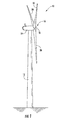
- FIG. 1 illustrates a side view of one embodiment of a wind turbine 10 according to the present disclosure.
- the wind turbine 10 generally includes a tower 12, a nacelle 14 mounted on the tower 12, and a rotor 16 coupled to the nacelle 14.
- the rotor 16 includes a rotatable hub 18 and at least one rotor blade 20 coupled to and extending outwardly from the hub 18.
- the rotor 16 includes three rotor blades 20.
- the rotor 16 may include more or less than three rotor blades 20.
- Each rotor blade 20 may be spaced about the hub 18 to facilitate rotating the rotor 16 to enable kinetic energy to be transferred from the wind into usable mechanical energy, and subsequently, electrical energy.
- the hub 18 may be rotatably coupled to an electric generator (not shown) positioned within the nacelle 14 to permit electrical energy to be produced.
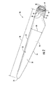
- the rotor blade 20 includes a blade root 22 configured for mounting the rotor blade 20 to the hub 18 of the wind turbine 10 ( FIG. 1 ) and a blade tip 24 disposed opposite the blade root 22.
- a body 26 of the rotor blade 20 may extend lengthwise between the blade root 22 and the blade tip 24 and may generally serve as the outer shell of the rotor blade 20.
- the body 26 may define an aerodynamic profile (e.g., by defining an airfoil shaped cross-section, such as a symmetrical or cambered airfoil-shaped cross-section) to enable the rotor blade 20 to capture kinetic energy from the wind using known aerodynamic principles.
- the body 26 may generally include a pressure side 28 and a suction side 30 extending between a leading edge 32 and a trailing edge 34.
- the rotor blade 20 may have a span 36 defining the total length of the body 26 between the blade root 22 and the blade tip 24 and a chord 38 defining the total length of the body 26 between the leading edge 32 and the trailing edge 34.
- the chord 38 may vary in length with respect to the span 26 as the body 26 extends from the blade root 22 to the blade tip 24.
- each root attachment assembly 40 may include a barrel nut 42 mounted within a portion of the blade root 22 and a root bolt 44 coupled to and extending from the barrel nut 42 so as to project outwardly from a root end 46 of the blade root 22.
- the barrel nut 42 may be eliminated from the root attachment assembly 40.
- each of the root attachment assemblies 40 may simply include a threaded root bolt 44 projecting outwardly from the root end 46 of the blade root 22. By projecting outwardly from the root end 46, the root bolts 44 may generally be used to couple the blade root 22 to the hub 18 (e.g., via a pitch bearing 50 ( FIG. 3 )), as will be described in greater detail below.
- FIGS. 3 and 4 several views of a rotor blade assembly 50 having shim plate 100 for mitigating loads in a pitch bearing 52 are illustrated in accordance with aspects of the present subject matter.
- FIG. 3 illustrates a cross-sectional view of the rotor blade assembly 50 having a plurality of shim plates 100 installed between the rotor blade 20 and the hub 18.
- FIG. 4 illustrates an exploded view of the rotor blade assembly 50 according to the present disclosure.
- the rotor blade assembly 50 includes the rotor blade 20 coupled to the hub 18 via the pitch bearing 52.
- the pitch bearing 52 includes an outer bearing race 54, an inner bearing race 56, and a plurality of roller elements (e.g., balls 58) disposed between the outer and inner races 54, 56.
- the outer race 54 is generally configured to be mounted to the hub 18 using a plurality of hub bolts 62 and/or other suitable fastening mechanisms.
- the inner race 56 is generally configured to be mounted to the blade root 22 of the rotor blade 20 using root bolts 44.
- the root bolt(s) 44 extend between a first end 64 and a second end 66.
- each root bolt 44 may be configured to be coupled to a portion of the inner race 56, such as by coupling the first end 64 to the inner bearing race 56 using an attachment nut 68 and/or other suitable fastening mechanism.
- the second end 66 of each root bolt 44 may be configured to be coupled to the blade root 22 via a barrel nut 42.
- the inner race 56 may be configured to be rotated relative to the outer race 54 (via the roller elements 58) to allow the pitch angle of each rotor blade 20 to be adjusted. As shown in FIG. 3 , such relative rotation of the outer and inner races 54, 56 may be achieved using a pitch adjustment mechanism 72 mounted within a portion of the hub 18.
- the pitch adjustment mechanism 72 may include any suitable components and may have any suitable configuration that allows the mechanism 72 to function as described herein.
- the pitch adjustment mechanism 72 may include a pitch drive motor 74 (e.g., an electric motor), a pitch drive gearbox 76, and a pitch drive pinion 78.
- the pitch drive motor 74 may be coupled to the pitch drive gearbox 76 so that the motor 74 imparts mechanical force to the gearbox 76.
- the gearbox 76 may be coupled to the pitch drive pinion 78 for rotation therewith.
- the pinion 78 may, in turn, be in rotational engagement with the inner race 56.
- a plurality of gear teeth 80 may be formed along an inner circumference 86 of the inner race 56, with the gear teeth 80 being configured to mesh with corresponding gear teeth 82 formed on the pinion 78.
- rotation of the pitch drive pinion 78 results in rotation of the inner race 56 relative to the outer race 54 and, thus, rotation of the rotor blade 20 relative to the hub 18.
- FIG. 4 an exploded view of the rotor blade assembly 50 according to the present disclosure is illustrated.
- three shim plates 100 are spaced apart circumferentially about the inner race 56 of the pitch bearing 52.
- the shim plates 100 may be configured between a top surface 88 of the inner race 56 and the blade root 22. More specifically, at least one of the shim plates 100 is located approximate to a pressure side of the pitch bearing 52 corresponding to the pressure side surface 28 of the rotor blade 20, whereas two shim plates 100 are located approximate to a suction side of the pitch bearing 52 corresponding to the suction side surface 30 of the rotor blade 20.
- one or more shim plates 100 may be spaced circumferentially about the outer race 54 of the pitch bearing 52 and between the outer race 54 and the hub 18.
- one shim plate 100 is located between the outer race 54 and the hub 18. More specifically, the shim plate 100 is configured between a bottom surface 92 of the outer race 54 and the hub 18.
- the rotor blade assembly 50 may include any number of shim plates 100 and the shim plates 100 may be arranged at any location along the circumference of the pitch bearing 52 and between either the inner race and the blade root or the outer race and the hub. As such, the shim plates 100 can be located at any location on the pitch bearing 52 experiencing uneven loading, such as, for example, corresponding to a hard pressure spot.
- the top surface 88 of the inner race 56 defines a radial dimension R 1 ( FIG. 4 ), whereas and the shim plate 100 defines a width W ( FIG. 5 ) that is equal to or less than the radial dimension R 1 .
- the shim plate 100 fits within the radial dimension R 1 of the inner race 56 and does not extend within the open area within the inner race 56. Additionally, in such an embodiment, the width W of the shim plate 100 does not interfere with the outer race 54 when the shim plate 100 is configured between the inner race 56 and the blade root 22.
- the bottom surface 92 of the outer race 54 defines a radial dimension R 2 such that the width W of the shim plate 100 is equal to or less than the radial dimension R 2 .
- the shim plate 100 fits within the radial dimension R 2 of the outer race 54 and does not interfere with the inner race 56 when the shim plate 100 is configured between the outer race 54 and the hub 18.
- FIGS. 5-11 various detailed embodiments of the shim plate according to the present disclosure are illustrated.
- FIGS. 5 and 6 illustrates close-up perspective views of various embodiments of the shim plate according to the present disclosure
- FIGS. 7-11 illustrate top and side views of further embodiments of the shim plate according to the present disclosure.
- the shim plate 100, 150, 200 has a base 102, 152, 202 and at least one tapered edge 104, 154, 204.
- the base 102 may have a substantially rectangular cross-section as indicated by section A-A. As such, the base 102 has substantially linear radial edges 110.
- the base 202 may have a substantially tapered cross-section as indicated by section B-B.
- the base 102 has at least one substantially tapered radial edge 210.
- the shim plate 200 may include a tapered radial edge 210 across the full shim width W or across only a portion of the shim width W.
- the base 102 has a height H (or thickness) and a total length L 1 .
- the total length L 1 may be any suitable length and typically ranges from about 200 millimeters (mm) to about 3 meters (m).
- the height H may be any suitable height and/or thickness and typically ranges from about 0.5 mm to about 10 mm, such as, for example, 0.7 mm.
- the base 102 may have any suitable shape so as to fit in the desired locations as described herein.
- the base 102 has a typically arcuate shape so as to correspond with the shape of the inner 56 and outer 54 races of the pitch bearing 52.
- the base 102, 152 may have a rectangular, square, triangular, circular, or similar shape.
- the base 152 has a rectangular shape.
- the tapered edge(s) 104, 154, 204 are provided to allow intimate contact at all bearing perimeter locations with a finite in-plane shear stress in the blade shell. Further, the tapered edge(s) 104, 154, 204 minimize added friction that may exist due to rotation of the inner 56 and outer 54 bearing races. It should be understand that the term “tapered edges” is meant to encompass at least a tapered-sloped edge, as well as a tapered-stepped edge, as will be discussed in more detail herein. As shown in the embodiments of FIGS. 5 and 9 , the shim plate 100 may include opposing tapered edges 104 having corresponding slopes. For example, as depicted in the embodiment of FIG.
- the slope of each of the tapered edges 104 is equal to L 2 /H and L 3 /H, respectively.
- the lengths L 2 , L 3 of the tapered edges 104 may be any suitable length and typically ranges from about 250 mm to about 750 mm, such as, for example, 500 mm.
- the height H may be any suitable height and typically ranges from about 0.2 mm to about 10 mm, such as, for example, 0.7 mm.
- the corresponding slopes of the tapering edges ranges from about 0.00026 to about 0.04, such, for example, 0.0014.
- the slopes of the tapering edges 104 may be any appropriate slope to provide appropriate contact between the rotor blade 20 and the pitch bearing 52 and/or the hub 18 and the pitch bearing 52.
- the shim plates 300, 400 may include opposing tapered edges 304, 404 having a step configuration. More specifically, as shown in FIG. 10 , the shim plate 300 may include multiple shim layers 308 having varying lengths and stacked atop one another until a suitable height H or thickness is obtained. It should be understood that the shim plates 100, 200, 300, 400 described herein may include any number of shim layers 108, 308, 408 from one to greater than one. For example, as shown in FIG. 10 , the illustrated embodiment includes two shim layers 308, whereas the shim plate 400 of FIG. 11 includes four shim layers 408. In addition, each of the shim layers 308, 408 has a varying length such that the varying lengths (e.g. L 4 and L 5 ) form the opposing tapered edges 304, 404 having a step configuration.
- the varying lengths e.g. L 4 and L 5
- the opposing tapered edges 104, 204, 304, 404 may be identical to one another or may vary according to any of the embodiments described herein.
- one of the edges may have a tapered-sloped configuration (as shown in FIG. 9 ), whereas the opposing edge may have a step configuration (as shown in FIGS. 10 and 11 ).
- both edges may have a tapered-sloped configuration; however, the slopes may vary.
- the shim plate 100 may include one or more through holes 106 for coupling the shim plate 100 between the inner race 56 and the blade root 22 or between the outer race 54 and the hub 18.
- the through holes 106 of the shim plate 100 may correspond to the root bolts 44 of the blade root 22 or the hub bolts 62 of the hub 18.
- the shim plate 150 may include one or more segments 158, wherein each segment 158 has at least one slot 160.
- the segments 158 may be inner and outer interlocking segments for inserting the shim plate 150 around corresponding bolts 44, 62.
- the slots 160 of the segments 158 may form the through holes 156 when the segments 158 are connected, i.e. inserted around a blade bolt or a hub bolt.
- the shim plate 100 may be secured between the inner race 56 and the blade root 22 or between the outer race 54 and the hub 18 using any other suitable means, such as adhesives or friction.
- the shim plate(s) described herein may be constructed of any suitable materials so as to mitigate loads experienced by the pitch bearing. In one embodiment, it is desirable for the joint of the material to be as stiff as possible. As such, in various embodiments, the shim plate(s) may be constructed of metal, such as steel or similar. In a further embodiment, the shim plate may be constructed of a composite material, such as a fiberglass laminate, similar to the rotor blade.
- the method 500 includes a step 502 of providing a rotor blade configured to couple to a hub of a wind turbine via the pitch bearing.
- the method 500 includes identifying at least one location on the pitch bearing experiencing a loading (step 504) and then installing at least one shim plate at the identified location (step 506).
- the method 500 then includes securing the rotor blade to the hub of the wind turbine via the pitch bearing such that the at least one shim plate mitigates the loading in the pitch bearing during operation of the wind turbine (step 508).
- the step 504 of identifying at least one location on the pitch bearing experiencing a loading further includes identifying a spar cap in the rotor blade.
- one or more shim plates can be placed in-line with the spar cap.
- one or more shim plates can be inserted on a pressure side surface of the rotor blade in-line with the spar cap, whereas one or more shim plates can be inserted on the suction side surface of the rotor blade adjacent to the spar cap.
- the step of installing at least one shim plate at the identified location further includes installing at least one shim plate between the rotor blade and the hub and spacing a plurality of shim plates circumferentially about the pitch bearing.
- the method 500 may include sizing the shim plate to accommodate the loading.
- the loading may be representative of bearing ball contact stresses, blade root resultant moments, hard pressure spots or similar.
- the step 506 of installing the at least one shim plate at the identified location may completed using a variety of techniques.
- the method may include positioning the rotor blade in a six o'clock position relative to the hub, loosening one or more blade bolts until a gap opens between the rotor blade and the hub, inserting the at least one shim plate over one of the blade bolts, and tightening the blade bolts such that the at least one shim plate is secured between the rotor blade and the hub so as to mitigate loads in the pitch bearing.
- one or more shim plates may be screwed into an end face of the pitch bearing, such as a top or bottom surface of the pitch bearing.
- the segments may be inserted around the blade bolts or hub bolts via corresponding slots and then secured between the rotor blade and the hub.
- one or more shim plates may be inserted over root bolts 44 before the rotor blade is coupled to the hub via the pitch bearing.
- one or more shim plates may be inserted over the hub bolts 62.
- the method 500 may include removing one or more of the blade bolts, installing one or more of the shim plates in the location(s) of the corresponding removed blade bolts, and then replacing the blade bolts.
- the method 500 as described herein may also include machining the pitch bearing so as to provide one or more shim plates or protrusions integral with the pitch bearing, such as on the top or bottom surfaces of the pitch bearing.
- the method may include machining the hub or the rotor blade such that one or more shim plates or protrusions are provided in an end face of the hub or the rotor blade.
Landscapes
- Engineering & Computer Science (AREA)
- General Engineering & Computer Science (AREA)
- Mechanical Engineering (AREA)
- Life Sciences & Earth Sciences (AREA)
- Sustainable Development (AREA)
- Sustainable Energy (AREA)
- Chemical & Material Sciences (AREA)
- Combustion & Propulsion (AREA)
- Physics & Mathematics (AREA)
- Fluid Mechanics (AREA)
- Wind Motors (AREA)
Abstract
Description
- The present subject matter relates generally to wind turbines and, more particularly, to a rotor blade assembly for a wind turbine with one or more shim plates for mitigating pitch bearing loading.
- Wind power is considered one of the cleanest, most environmentally friendly energy sources presently available, and wind turbines have gained increased attention in this regard. A modem wind turbine typically includes a tower, generator, gearbox, nacelle, and one or more rotor blades. The rotor blades capture kinetic energy from wind using known airfoil principles and transmit the kinetic energy through rotational energy to turn a shaft coupling the rotor blades to a gearbox, or if a gearbox is not used, directly to the generator. The generator then converts the mechanical energy to electrical energy that may be deployed to a utility grid.
- To ensure that wind power remains a viable energy source, efforts have been made to increase energy outputs by modifying the size and capacity of wind turbines. One such modification has been to increase the length of the rotor blades. However, as is generally understood, the loading on a rotor blade is a function of blade length, along with wind speed and turbine operating states. Thus, longer rotor blades may be subject to increased loading, particularly when a wind turbine is operating in highspeed wind conditions.
- During the operation of a wind turbine, the loads acting on a rotor blade are transmitted through the blade and into the blade root. Thereafter, the loads are transmitted through a pitch bearing disposed at the interface between the rotor blade and the wind turbine hub. Typically, the hub has a much higher stiffness than the rotor blades. Thus, due to the stiffness differential between the hub and the rotor blades, the pitch bearings are often subjected to extreme, varying and/or opposing loads. For example, the inner race of each pitch bearing (i.e., the portion typically coupled to the rotor blades) may be subjected to varying, localized loads resulting from flapwise or edgewise bending of the rotor blades, whereas the outer race of each pitch bearing (i.e., the portion typically coupled to the hub) may be subjected to lower and/or differing loads. This variation in loading across the inner and outer races can result in substantial damage to the pitch bearings caused by high bearing contact stresses, high blade root resultant moments, and hard pressure spots.
- Various systems and methods have been employed to control such varying loads in an effort to protect the pitch bearing. For example, one method involves loosening the nuts on the bolts in line with the hard pressure spots such that gaps are created when the pitch bearing is overloaded. Such a method, however, tends to overload adjacent bolts and is therefore not very effective.
- Accordingly, an improved system and method for mitigating loads in a pitch bearing, such as ball and raceway bearing contact stresses, would be desired in the art. For example, a rotor blade assembly having a shim plate configured to mitigate bearing contact stresses would be advantageous.
- Various aspects and advantages of the invention will be set forth in part in the following description, or may be clear from the description, or may be learned through practice of the invention.
- In one aspect, the present subject matter is directed to a rotor blade assembly for a wind turbine. The rotor blade assembly includes a rotor blade, a pitch bearing, and at least one shim plate. The rotor blade includes a body extending between a blade root and a blade tip. The pitch bearing includes an outer race, an inner race, and a plurality of roller elements between the outer race and the inner race. As such, the inner race is rotatable relative to the outer race. Further, the inner race is coupled to the blade root. The at least one shim plate is configured between the inner race and the blade root so as to mitigate loads in the pitch bearing.
- In another aspect a rotor blade assembly for a wind turbine having a rotor blade, a pitch bearing, and at least one shim plate is disclosed. The rotor blade includes a body extending between a blade root and a blade tip. The pitch bearing includes an outer race, an inner race, and a plurality of roller elements between the outer race and the inner race such that the inner race is rotatable relative to the outer race. Further, the outer race is coupled to a hub of the wind turbine. The at least one shim plate is configured between the outer race and the hub so as to mitigate loads in the pitch bearing.
- In still another aspect, a method for mitigating loads in a pitch bearing of a wind turbine is disclosed. The method includes providing a rotor blade configured to couple to a hub of a wind turbine via the pitch bearing, the pitch bearing comprising and outer race and an inner race; identifying at least one location on the pitch bearing experiencing a loading; installing at least one shim plate at the location; and, securing the rotor blade to the hub of the wind turbine via the pitch bearing such that the at least one shim plate mitigates the loading in the pitch bearing during operation of the wind turbine.
- Various features, aspects and advantages of the present invention will become better understood with reference to the following description and appended claims. The accompanying drawings, which are incorporated in and constitute a part of this specification, illustrate embodiments of the invention and, together with the description, serve to explain the principles of the invention. In the drawings:
-
FIG. 1 illustrates a perspective view of one embodiment of a wind turbine; -
FIG. 2 illustrates a perspective view of one of the rotor blades of the wind turbine shown inFIG. 1 ; -
FIG. 3 illustrates a cross-sectional view of one embodiment of the rotor blade assembly in accordance with aspects of the present subject matter; -
FIG. 4 illustrates an exploded view of one embodiment of a rotor blade assembly according to the present disclosure; -
FIG. 5 illustrates a perspective view of one embodiment of a shim plate according to the present disclosure; -
FIG. 6 illustrates a perspective view of another embodiment of a shim plate according to the present disclosure; -
FIG. 7 illustrates a top view of one embodiment of a shim plate according to the present disclosure; -
FIG. 8 illustrates a top view of another embodiment of a shim plate according to the present disclosure; -
FIG. 9 illustrates a side view of one embodiment of a shim plate according to the present disclosure; -
FIG. 10 illustrates a side view of another embodiment of a shim plate according to the present disclosure; -
FIG. 11 illustrates a side view of another embodiment of a shim plate according to the present disclosure; and -
FIG. 12 illustrates a method for mitigating loads in a pitch bearing of a wind turbine according to the present disclosure. - Reference now will be made in detail to embodiments of the invention, one or more examples of which are illustrated in the drawings. Each example is provided by way of explanation of the invention, not limitation of the invention. In fact, it will be apparent to those skilled in the art that various modifications and variations can be made in the present invention without departing from the scope or spirit of the invention. For instance, features illustrated or described as part of one embodiment can be used with another embodiment to yield a still further embodiment. Thus, it is intended that the present invention covers such modifications and variations as come within the scope of the appended claims and their equivalents.
- In general, the present subject matter is directed to a rotor blade assembly for a wind turbine having at least one shim plate configured between a rotor blade a hub to mitigate loads in a pitch bearing, such as ball contact stresses. The shim plate is generally a thin, optionally tapered or wedged piece of material, used to fill a gap or space between a rotor blade and a hub of the wind turbine. The shim plate(s) may also be integral with the rotor blade, the hub, and/or the pitch bearing. The pitch bearing generally includes an outer race, an inner race, and a plurality of roller elements between the outer race and the inner race such that the inner race is rotatable relative to the outer race. As such, the at least one shim plate may be configured to fit between the inner race and a blade root of the rotor blade or between the outer race and a hub of the wind turbine so as to mitigate loads in the pitch bearing.
- Accordingly, the present subject matter as described herein provides many technical and commercial advantages. For example, the addition of one or more shim plates configured between a new or existing rotor blade and a wind turbine hub can increase bearing load capacity without substantially increasing installation and/or maintenance costs. Further, retrofitting existing wind turbines with one or more shim plates as disclosed herein does not require the use of costly cranes.
- Referring now to the drawings,
FIG. 1 illustrates a side view of one embodiment of awind turbine 10 according to the present disclosure. As shown, thewind turbine 10 generally includes atower 12, anacelle 14 mounted on thetower 12, and arotor 16 coupled to thenacelle 14. Therotor 16 includes arotatable hub 18 and at least onerotor blade 20 coupled to and extending outwardly from thehub 18. For example, in the illustrated embodiment, therotor 16 includes threerotor blades 20. However, in an alternative embodiment, therotor 16 may include more or less than threerotor blades 20. Eachrotor blade 20 may be spaced about thehub 18 to facilitate rotating therotor 16 to enable kinetic energy to be transferred from the wind into usable mechanical energy, and subsequently, electrical energy. For instance, thehub 18 may be rotatably coupled to an electric generator (not shown) positioned within thenacelle 14 to permit electrical energy to be produced. - Referring now to
FIG. 2 , a perspective view of one of therotor blades 20 shown inFIG. 1 is illustrated in accordance with aspects of the present subject matter. As shown, therotor blade 20 includes ablade root 22 configured for mounting therotor blade 20 to thehub 18 of the wind turbine 10 (FIG. 1 ) and ablade tip 24 disposed opposite theblade root 22. Abody 26 of therotor blade 20 may extend lengthwise between theblade root 22 and theblade tip 24 and may generally serve as the outer shell of therotor blade 20. As is generally understood, thebody 26 may define an aerodynamic profile (e.g., by defining an airfoil shaped cross-section, such as a symmetrical or cambered airfoil-shaped cross-section) to enable therotor blade 20 to capture kinetic energy from the wind using known aerodynamic principles. Thus, thebody 26 may generally include apressure side 28 and asuction side 30 extending between aleading edge 32 and a trailingedge 34. Additionally, therotor blade 20 may have aspan 36 defining the total length of thebody 26 between theblade root 22 and theblade tip 24 and achord 38 defining the total length of thebody 26 between theleading edge 32 and the trailingedge 34. As is generally understood, thechord 38 may vary in length with respect to thespan 26 as thebody 26 extends from theblade root 22 to theblade tip 24. - Moreover, as shown, the
rotor blade 20 may also include a plurality of T-bolts orroot attachment assemblies 40 for coupling theblade root 20 to thehub 18 of thewind turbine 10. In general, eachroot attachment assembly 40 may include abarrel nut 42 mounted within a portion of theblade root 22 and aroot bolt 44 coupled to and extending from thebarrel nut 42 so as to project outwardly from aroot end 46 of theblade root 22. Alternatively, thebarrel nut 42 may be eliminated from theroot attachment assembly 40. For example, each of theroot attachment assemblies 40 may simply include a threadedroot bolt 44 projecting outwardly from theroot end 46 of theblade root 22. By projecting outwardly from theroot end 46, theroot bolts 44 may generally be used to couple theblade root 22 to the hub 18 (e.g., via a pitch bearing 50 (FIG. 3 )), as will be described in greater detail below. - Referring now to
FIGS. 3 and4 , several views of arotor blade assembly 50 havingshim plate 100 for mitigating loads in apitch bearing 52 are illustrated in accordance with aspects of the present subject matter. Specifically,FIG. 3 illustrates a cross-sectional view of therotor blade assembly 50 having a plurality ofshim plates 100 installed between therotor blade 20 and thehub 18. Similarly,FIG. 4 illustrates an exploded view of therotor blade assembly 50 according to the present disclosure. - As shown, the
rotor blade assembly 50 includes therotor blade 20 coupled to thehub 18 via thepitch bearing 52. Thepitch bearing 52 includes anouter bearing race 54, aninner bearing race 56, and a plurality of roller elements (e.g., balls 58) disposed between the outer andinner races outer race 54 is generally configured to be mounted to thehub 18 using a plurality ofhub bolts 62 and/or other suitable fastening mechanisms. Similarly, theinner race 56 is generally configured to be mounted to theblade root 22 of therotor blade 20 usingroot bolts 44. For example, as particularly shown inFIG. 3 , the root bolt(s) 44 extend between afirst end 64 and asecond end 66. Thefirst end 64 of eachroot bolt 44 may be configured to be coupled to a portion of theinner race 56, such as by coupling thefirst end 64 to theinner bearing race 56 using anattachment nut 68 and/or other suitable fastening mechanism. Thesecond end 66 of eachroot bolt 44 may be configured to be coupled to theblade root 22 via abarrel nut 42. - As is generally understood, the
inner race 56 may be configured to be rotated relative to the outer race 54 (via the roller elements 58) to allow the pitch angle of eachrotor blade 20 to be adjusted. As shown inFIG. 3 , such relative rotation of the outer andinner races pitch adjustment mechanism 72 mounted within a portion of thehub 18. In general, thepitch adjustment mechanism 72 may include any suitable components and may have any suitable configuration that allows themechanism 72 to function as described herein. For example, as shown in the illustrated embodiment, thepitch adjustment mechanism 72 may include a pitch drive motor 74 (e.g., an electric motor), apitch drive gearbox 76, and apitch drive pinion 78. In such an embodiment, thepitch drive motor 74 may be coupled to thepitch drive gearbox 76 so that themotor 74 imparts mechanical force to thegearbox 76. Similarly, thegearbox 76 may be coupled to thepitch drive pinion 78 for rotation therewith. Thepinion 78 may, in turn, be in rotational engagement with theinner race 56. For example, as shown inFIGS. 3 and4 , a plurality ofgear teeth 80 may be formed along aninner circumference 86 of theinner race 56, with thegear teeth 80 being configured to mesh withcorresponding gear teeth 82 formed on thepinion 78. Thus, due to meshing of thegear teeth pitch drive pinion 78 results in rotation of theinner race 56 relative to theouter race 54 and, thus, rotation of therotor blade 20 relative to thehub 18. - Referring now to
FIG. 4 , an exploded view of therotor blade assembly 50 according to the present disclosure is illustrated. As shown in the illustrated embodiment, threeshim plates 100 are spaced apart circumferentially about theinner race 56 of thepitch bearing 52. As such, theshim plates 100 may be configured between atop surface 88 of theinner race 56 and theblade root 22. More specifically, at least one of theshim plates 100 is located approximate to a pressure side of the pitch bearing 52 corresponding to thepressure side surface 28 of therotor blade 20, whereas twoshim plates 100 are located approximate to a suction side of the pitch bearing 52 corresponding to thesuction side surface 30 of therotor blade 20. Additionally, one ormore shim plates 100 may be spaced circumferentially about theouter race 54 of the pitch bearing 52 and between theouter race 54 and thehub 18. For example, as illustrated, oneshim plate 100 is located between theouter race 54 and thehub 18. More specifically, theshim plate 100 is configured between abottom surface 92 of theouter race 54 and thehub 18. - It should be understood that the
rotor blade assembly 50 may include any number ofshim plates 100 and theshim plates 100 may be arranged at any location along the circumference of the pitch bearing 52 and between either the inner race and the blade root or the outer race and the hub. As such, theshim plates 100 can be located at any location on the pitch bearing 52 experiencing uneven loading, such as, for example, corresponding to a hard pressure spot. - In another embodiment, the
top surface 88 of theinner race 56 defines a radial dimension R1 (FIG. 4 ), whereas and theshim plate 100 defines a width W (FIG. 5 ) that is equal to or less than the radial dimension R1. As such, in various embodiments, theshim plate 100 fits within the radial dimension R1 of theinner race 56 and does not extend within the open area within theinner race 56. Additionally, in such an embodiment, the width W of theshim plate 100 does not interfere with theouter race 54 when theshim plate 100 is configured between theinner race 56 and theblade root 22. Similarly, thebottom surface 92 of theouter race 54 defines a radial dimension R2 such that the width W of theshim plate 100 is equal to or less than the radial dimension R2. As such, in various embodiments, theshim plate 100 fits within the radial dimension R2 of theouter race 54 and does not interfere with theinner race 56 when theshim plate 100 is configured between theouter race 54 and thehub 18. - Referring now to
FIG. 5-11 , various detailed embodiments of the shim plate according to the present disclosure are illustrated. For instance,FIGS. 5 and 6 illustrates close-up perspective views of various embodiments of the shim plate according to the present disclosure, whereasFIGS. 7-11 illustrate top and side views of further embodiments of the shim plate according to the present disclosure. As shown specifically inFIGS. 5-8 theshim plate base tapered edge FIG. 5 , thebase 102 may have a substantially rectangular cross-section as indicated by section A-A. As such, thebase 102 has substantially linear radial edges 110. In an alternative embodiment, as shown inFIG. 6 , thebase 202 may have a substantially tapered cross-section as indicated by section B-B. As such, thebase 102 has at least one substantially taperedradial edge 210. Accordingly, theshim plate 200 may include a taperedradial edge 210 across the full shim width W or across only a portion of the shim width W. - As shown in
FIG. 9 , thebase 102 has a height H (or thickness) and a total length L1. The total length L1 may be any suitable length and typically ranges from about 200 millimeters (mm) to about 3 meters (m). The height H may be any suitable height and/or thickness and typically ranges from about 0.5 mm to about 10 mm, such as, for example, 0.7 mm. Further, thebase 102 may have any suitable shape so as to fit in the desired locations as described herein. For example, as shown inFIGS. 5-7 , thebase 102 has a typically arcuate shape so as to correspond with the shape of the inner 56 and outer 54 races of thepitch bearing 52. In alternative embodiments, thebase FIG. 8 , thebase 152 has a rectangular shape. - The tapered edge(s) 104, 154, 204 are provided to allow intimate contact at all bearing perimeter locations with a finite in-plane shear stress in the blade shell. Further, the tapered edge(s) 104, 154, 204 minimize added friction that may exist due to rotation of the inner 56 and outer 54 bearing races. It should be understand that the term "tapered edges" is meant to encompass at least a tapered-sloped edge, as well as a tapered-stepped edge, as will be discussed in more detail herein. As shown in the embodiments of
FIGS. 5 and9 , theshim plate 100 may include opposing taperededges 104 having corresponding slopes. For example, as depicted in the embodiment ofFIG. 9 , the slope of each of the taperededges 104 is equal to L2/H and L3/H, respectively. The lengths L2, L3 of the taperededges 104 may be any suitable length and typically ranges from about 250 mm to about 750 mm, such as, for example, 500 mm. As mentioned, the height H may be any suitable height and typically ranges from about 0.2 mm to about 10 mm, such as, for example, 0.7 mm. As such, the corresponding slopes of the tapering edges ranges from about 0.00026 to about 0.04, such, for example, 0.0014. Further, the slopes of the tapering edges 104 may be any appropriate slope to provide appropriate contact between therotor blade 20 and the pitch bearing 52 and/or thehub 18 and thepitch bearing 52. - Alternatively, as shown in
FIGS. 10 and 11 , theshim plates edges FIG. 10 , theshim plate 300 may includemultiple shim layers 308 having varying lengths and stacked atop one another until a suitable height H or thickness is obtained. It should be understood that theshim plates FIG. 10 , the illustrated embodiment includes twoshim layers 308, whereas theshim plate 400 ofFIG. 11 includes four shim layers 408. In addition, each of the shim layers 308, 408 has a varying length such that the varying lengths (e.g. L4 and L5) form the opposing taperededges - Further, the opposing tapered
edges FIG. 9 ), whereas the opposing edge may have a step configuration (as shown inFIGS. 10 and 11 ). In another embodiment, both edges may have a tapered-sloped configuration; however, the slopes may vary. - Referring back to
FIG. 5 , theshim plate 100 may include one or more throughholes 106 for coupling theshim plate 100 between theinner race 56 and theblade root 22 or between theouter race 54 and thehub 18. As such, the throughholes 106 of theshim plate 100 may correspond to theroot bolts 44 of theblade root 22 or thehub bolts 62 of thehub 18. In an additional embodiment, as shown inFIG. 8 , theshim plate 150 may include one ormore segments 158, wherein eachsegment 158 has at least oneslot 160. Thesegments 158 may be inner and outer interlocking segments for inserting theshim plate 150 around correspondingbolts slots 160 of thesegments 158 may form the throughholes 156 when thesegments 158 are connected, i.e. inserted around a blade bolt or a hub bolt. In alternate embodiments, theshim plate 100 may be secured between theinner race 56 and theblade root 22 or between theouter race 54 and thehub 18 using any other suitable means, such as adhesives or friction. - It should also be understood that the shim plate(s) described herein may be constructed of any suitable materials so as to mitigate loads experienced by the pitch bearing. In one embodiment, it is desirable for the joint of the material to be as stiff as possible. As such, in various embodiments, the shim plate(s) may be constructed of metal, such as steel or similar. In a further embodiment, the shim plate may be constructed of a composite material, such as a fiberglass laminate, similar to the rotor blade.
- Referring now to
FIG. 12 , one embodiment of amethod 500 for mitigating loads in a pitch bearing of a wind turbine according to the present disclosure is illustrated. Themethod 500 includes astep 502 of providing a rotor blade configured to couple to a hub of a wind turbine via the pitch bearing. Themethod 500 includes identifying at least one location on the pitch bearing experiencing a loading (step 504) and then installing at least one shim plate at the identified location (step 506). Themethod 500 then includes securing the rotor blade to the hub of the wind turbine via the pitch bearing such that the at least one shim plate mitigates the loading in the pitch bearing during operation of the wind turbine (step 508). - In one embodiment, the
step 504 of identifying at least one location on the pitch bearing experiencing a loading further includes identifying a spar cap in the rotor blade. As such, one or more shim plates can be placed in-line with the spar cap. In another embodiment, one or more shim plates can be inserted on a pressure side surface of the rotor blade in-line with the spar cap, whereas one or more shim plates can be inserted on the suction side surface of the rotor blade adjacent to the spar cap. In another embodiment, the step of installing at least one shim plate at the identified location further includes installing at least one shim plate between the rotor blade and the hub and spacing a plurality of shim plates circumferentially about the pitch bearing. In addition, themethod 500 may include sizing the shim plate to accommodate the loading. In various embodiments, the loading may be representative of bearing ball contact stresses, blade root resultant moments, hard pressure spots or similar. - The
step 506 of installing the at least one shim plate at the identified location may completed using a variety of techniques. For example, in one embodiment, where the rotor blade is being retrofitted uptower with the one or more shim plates, the method may include positioning the rotor blade in a six o'clock position relative to the hub, loosening one or more blade bolts until a gap opens between the rotor blade and the hub, inserting the at least one shim plate over one of the blade bolts, and tightening the blade bolts such that the at least one shim plate is secured between the rotor blade and the hub so as to mitigate loads in the pitch bearing. In another embodiment, one or more shim plates may be screwed into an end face of the pitch bearing, such as a top or bottom surface of the pitch bearing. In still an additional embodiment, where one or more shim plates are configured in multiple segments each having a slot, the segments may be inserted around the blade bolts or hub bolts via corresponding slots and then secured between the rotor blade and the hub. In yet another embodiment, one or more shim plates may be inserted overroot bolts 44 before the rotor blade is coupled to the hub via the pitch bearing. Additionally, one or more shim plates may be inserted over thehub bolts 62. In another embodiment, themethod 500 may include removing one or more of the blade bolts, installing one or more of the shim plates in the location(s) of the corresponding removed blade bolts, and then replacing the blade bolts. - The
method 500 as described herein may also include machining the pitch bearing so as to provide one or more shim plates or protrusions integral with the pitch bearing, such as on the top or bottom surfaces of the pitch bearing. In another embodiment, the method may include machining the hub or the rotor blade such that one or more shim plates or protrusions are provided in an end face of the hub or the rotor blade. As such, the non-flat mating surfaces between the pitch bearing and the rotor blade and/or the pitch bearing and the hub mitigates loads in the pitch bearing. - This written description uses examples to disclose the invention, including the preferred mode, and also to enable any person skilled in the art to practice the invention, including making and using any devices or systems and performing any incorporated methods. The patentable scope of the invention is defined by the claims, and may include other examples that occur to those skilled in the art. Such other examples are intended to be within the scope of the claims if they include structural elements that do not differ from the literal language of the claims, or if they include equivalent structural elements with insubstantial differences from the literal languages of the claims.
- Various aspects and embodiments of the present invention are defined by the following numbered clauses:
- 1. A rotor blade assembly for a wind turbine, the rotor blade assembly comprising:
- a rotor blade including a body extending between a blade root and a blade tip;
- a pitch bearing comprising an outer race, an inner race, and a plurality of roller elements between the outer race and the inner race such that the inner race is rotatable relative to the outer race, the inner race being coupled to the blade root, the outer race configured to couple to a hub of the wind turbine; and
- at least one shim plate configured between the inner race and the blade root, wherein the shim plate is configured to mitigate loads in the pitch bearing.
- 2. The rotor blade assembly of clause 1, wherein the inner race comprises a top surface defining a radial dimension, the shim plate having a width that is equal to or less than the radial dimension.
- 3. The rotor blade assembly of any preceding clause, further comprising a plurality of shim plates spaced circumferentially about the inner race, the plurality of shim plates secured between the inner race and the blade root.
- 4. The rotor blade assembly of any preceding clause, wherein at least one of the shim plates is located on a pressure side of the pitch bearing corresponding to a pressure side surface of the rotor blade and at least one of the shim plates is located on a suction side of the pitch bearing corresponding to a suction side surface of the rotor blade.
- 5. The rotor blade assembly of any preceding clause, further comprising at least one shim plate between the outer race and the hub.
- 6. The rotor blade assembly of any preceding clause, wherein the at least one shim plate comprises a base and at least one tapered edge.
- 7. The rotor blade assembly of any preceding clause, wherein the at least one shim plate comprises one or more through holes, each of the through holes corresponding to one of a root bolt of the blade root or a hub bolt of the hub, wherein the through holes are configured to couple the shim plate between one of the inner race and the blade root or the outer race and the hub.
- 8. The rotor blade assembly of any preceding clause, wherein the at least one shim plate comprises one or more segments, each of the segments comprising a slot, wherein the slots of each segment form the through holes when the segments are connected.
- 9. The rotor blade assembly of any preceding clause, wherein the at least one shim plate further comprises opposing tapered longitudinal edges.
- 10. The rotor blade assembly of any preceding clause, wherein the at least one shim plate further comprises a tapered radial edge.
- 11. The rotor blade assembly of any preceding clause, wherein the at least one shim plate comprises a plurality of shim layers having varying lengths.
- 12. The rotor blade assembly of any preceding clause, wherein the plurality of shim layers are stacked atop each other such that the varying lengths form opposing tapered edges having a step configuration.
- 13. The rotor blade assembly of any preceding clause, wherein the at least one shim plate is formed integrally with one of the blade root or the pitch bearing.
- 14. A rotor blade assembly for a wind turbine, the rotor blade assembly comprising:
- a rotor blade including a body extending between a blade root and a blade tip;
- a pitch bearing comprising an outer race, an inner race, and a plurality of roller elements between the outer race and the inner race such that the inner race is rotatable relative to the outer race, the outer race being coupled to a hub of the wind turbine; and
- at least one shim plate configured between the outer race and the hub, wherein the shim plate is configured to mitigate loads in the pitch bearing.
- 15. The rotor blade assembly of any preceding clause, wherein the outer race comprises a bottom surface defining a radial dimension, the shim plate having a width that is equal to or less than the radial dimension.
- 16. The rotor blade assembly of any preceding clause, wherein the shim plate further comprises opposing tapered longitudinal edges.
- 17. The rotor blade assembly of any preceding clause, wherein the at least one shim plate further comprises a tapered radial edge.
- 18. A method for mitigating loads in a pitch bearing of a wind turbine, the method comprising:
- providing a rotor blade configured to couple to a hub of a wind turbine via the pitch bearing, the pitch bearing comprising and outer race and an inner race;
- identifying at least one location on the pitch bearing experiencing a loading;
- installing at least one shim plate at the identified location; and,
- securing the rotor blade to the hub of the wind turbine via the pitch bearing such that the shim plate mitigates the loading in the pitch bearing during operation of the wind turbine.
- 19. The method of any preceding clause, further comprising sizing the shim plate to accommodate the loading.
- 20. The method of any preceding clause, wherein the loading is representative of at least one of bearing ball contact stresses, blade root resultant moments, or hard pressure spots.
Claims (15)
- A rotor blade assembly (50) for a wind turbine (10), the rotor blade assembly (50) comprising:a rotor blade (20) including a body extending between a blade root and a blade tip;a pitch bearing (52) comprising an outer race (54), an inner race (56), and a plurality of roller elements between the outer race (54) and the inner race (56) such that the inner race (56) is rotatable relative to the outer race (54), the inner race (56) being coupled to the blade root (46), the outer race (54) configured to couple to a hub of the wind turbine (10); andat least one shim plate (100) configured between the inner race (56) and the blade root, wherein the shim plate (100) is configured to mitigate loads in the pitch bearing (52).
- The rotor blade assembly (50) of claim 1, wherein the inner race (56) comprises a top surface defining a radial dimension, the shim plate (100) having a width that is equal to or less than the radial dimension.
- The rotor blade assembly (50) of any preceding claim, further comprising a plurality of shim plates (100) spaced circumferentially about the inner race (56), the plurality of shim plates (100) secured between the inner race (56) and the blade root (46).
- The rotor blade assembly (50) of claim 3, wherein at least one of the shim plates (100) is located on a pressure side of the pitch bearing (52) corresponding to a pressure side surface of the rotor blade (20) and at least one of the shim plates (100) is located on a suction side of the pitch bearing (52) corresponding to a suction side surface of the rotor blade (20).
- The rotor blade assembly (50) of any preceding claim, further comprising at least one shim plate (100) between the outer race (54) and the hub.
- The rotor blade assembly (50) of any preceding claim, wherein the at least one shim plate (100) comprises a base and at least one tapered edge.
- The rotor blade assembly (50) of any preceding claim, wherein the at least one shim plate (100) comprises one or more through holes, each of the through holes corresponding to one of a root bolt of the blade root or a hub bolt of the hub, wherein the through holes are configured to couple the shim plate between one of the inner race and the blade root or the outer race and the hub.
- The rotor blade assembly (50) of claim 7, wherein the at least one shim plate (100) comprises one or more segments, each of the segments comprising a slot, wherein the slots of each segment form the through holes when the segments are connected.
- The rotor blade assembly (50) of any preceding claim, wherein the at least one shim plate (100) further comprises opposing tapered longitudinal edges.
- The rotor blade assembly (50) of any preceding claim, wherein the at least one shim plate (100) further comprises a tapered radial edge.
- The rotor blade assembly (50) of any preceding claim, wherein the at least one shim plate (100) comprises a plurality of shim layers having varying lengths.
- The rotor blade assembly (50) of any preceding claim, wherein the plurality of shim layers are stacked atop each other such that the varying lengths form opposing tapered edges having a step configuration.
- A method (500) for mitigating loads in a pitch bearing (52) of a wind turbine (10), the method comprising:providing (502) a rotor blade (20) configured to couple to a hub of a wind turbine (10) via the pitch bearing (52), the pitch bearing (52) comprising an outer race (54) and an inner race (52);identifying (504) at least one location on the pitch bearing (52) experiencing a loading;installing (506) at least one shim plate (100) at the identified location; andsecuring (508) the rotor blade (20) to the hub of the wind turbine (10) via the pitch bearing (52) such that the shim plate (100) mitigates the loading in the pitch bearing during operation of the wind turbine (10).
- The method (500) of claim 13, further comprising sizing the shim plate (100) to accommodate the loading.
- The method (500) of claim 13 or claim 14, wherein the loading is representative of at least one of bearing ball contact stresses, blade root resultant moments, or hard pressure spots.
Applications Claiming Priority (1)
| Application Number | Priority Date | Filing Date | Title |
|---|---|---|---|
| US14/036,463 US9523348B2 (en) | 2013-09-25 | 2013-09-25 | Rotor blade assembly with shim plate for mitigation pitch bearing loads |
Publications (2)
| Publication Number | Publication Date |
|---|---|
| EP2853733A1 true EP2853733A1 (en) | 2015-04-01 |
| EP2853733B1 EP2853733B1 (en) | 2018-01-03 |
Family
ID=51542239
Family Applications (1)
| Application Number | Title | Priority Date | Filing Date |
|---|---|---|---|
| EP14185084.2A Active EP2853733B1 (en) | 2013-09-25 | 2014-09-17 | Rotor blade assembly with shim plate for mitigating pitch bearing loads |
Country Status (3)
| Country | Link |
|---|---|
| US (1) | US9523348B2 (en) |
| EP (1) | EP2853733B1 (en) |
| DK (1) | DK2853733T3 (en) |
Cited By (3)
| Publication number | Priority date | Publication date | Assignee | Title |
|---|---|---|---|---|
| EP3139034A1 (en) * | 2015-09-02 | 2017-03-08 | Siemens Aktiengesellschaft | Removal of a front top sliding pad of a yaw bearing of a wind turbine |
| EP3153730A1 (en) * | 2015-10-09 | 2017-04-12 | NTN-SNR Roulements | Blade-root bearing, oscillating system and rotating system |
| EP3872334A1 (en) * | 2020-12-23 | 2021-09-01 | Vestas Wind Systems A/S | A method of prolonging pitch bearing lifetime and pitch bearing |
Families Citing this family (8)
| Publication number | Priority date | Publication date | Assignee | Title |
|---|---|---|---|---|
| DK2933476T3 (en) * | 2014-04-17 | 2017-05-15 | Siemens Ag | Reinforced pitch bearing of a wind turbine |
| WO2017005264A1 (en) * | 2015-07-06 | 2017-01-12 | Vestas Wind Systems A/S | Segmented pitch ring for a wind turbine blade pitch system |
| DK3312414T3 (en) * | 2016-10-24 | 2021-05-31 | Nordex Energy Spain S A | WIND TURBLE AND WIND TURBLE PITCHLEJE |
| DK3318749T4 (en) * | 2016-11-04 | 2024-10-14 | Nordex Energy Spain Sau | WINDMILL |
| CN110232218B (en) * | 2019-05-17 | 2023-06-16 | 许昌许继风电科技有限公司 | Method and device for calculating strength of blade locking device of wind power generating set |
| EP3851668A1 (en) | 2020-01-17 | 2021-07-21 | Wobben Properties GmbH | Wind turbine, wind turbine rotor blade and blade bearing for a wind turbine |
| US11619211B2 (en) | 2020-10-30 | 2023-04-04 | General Electric Renovables Espana, S.L. | Wind turbine pitch bearing with friction enhancing insert layer |
| CN115450861A (en) * | 2022-09-30 | 2022-12-09 | 株洲时代新材料科技股份有限公司 | Buffer device for root of wind power generation blade |
Citations (3)
| Publication number | Priority date | Publication date | Assignee | Title |
|---|---|---|---|---|
| US20110138893A1 (en) * | 2010-08-30 | 2011-06-16 | Mitsubishi Heavy Industries, Ltd. | Method for adjusting unevenness of top flange of wind turbine generator tower |
| JP2013137074A (en) * | 2011-12-28 | 2013-07-11 | Mitsubishi Heavy Ind Ltd | Bearing for wind power generator and wind power generator |
| KR20130094075A (en) * | 2012-02-15 | 2013-08-23 | 삼성중공업 주식회사 | Apparatus for monitoring loose nut of wind turbine generator |
Family Cites Families (16)
| Publication number | Priority date | Publication date | Assignee | Title |
|---|---|---|---|---|
| DE10034958A1 (en) | 2000-07-19 | 2002-02-07 | Aloys Wobben | rotor blade hub |
| DE10140793A1 (en) | 2001-08-20 | 2003-03-06 | Gen Electric | Device for adjusting the rotor blade of a rotor of a wind turbine |
| EP1907692B2 (en) | 2005-07-05 | 2022-12-07 | Vestas Wind Systems A/S | A wind turbine pitch bearing, and use hereof |
| EP1907694B2 (en) | 2005-07-08 | 2016-01-20 | Vestas Wind Systems A/S | A wind turbine, a hub for a wind turbine and use hereof |
| WO2007112748A2 (en) | 2006-04-02 | 2007-10-11 | Vestas Wind Systems A/S | A pitch bearing for a wind turbine, a wind turbine and a method for servicing a bearing |
| EP1925860A1 (en) | 2006-11-02 | 2008-05-28 | Ecotecnia Energias Renovables S.L. | Device for fitting a seal |
| ES2301395B1 (en) | 2006-11-13 | 2009-05-01 | GAMESA INNOVATION & TECHNOLOGY, S.L. | REINFORCED BEARING OF A BLADDER OF A WINDER. |
| DE102007008166A1 (en) | 2007-02-14 | 2008-08-21 | Nordex Energy Gmbh | Wind energy plant with a pitch turning connection |
| DE102007008167C5 (en) | 2007-02-14 | 2016-07-07 | Nordex Energy Gmbh | Wind turbine with a rotor hub |
| DK2045464T4 (en) | 2007-10-01 | 2016-12-12 | Siemens Ag | Pitch rental for vindmøllerotorvinger |
| ES2379618B1 (en) | 2009-12-16 | 2013-03-26 | Acciona Windpower, S.A. | BEARING OF AEROGENERATOR AND AEROGENERATOR SHOVEL THAT MAKES USE OF IT. |
| CN102216610B (en) | 2010-02-10 | 2014-08-20 | 三菱重工业株式会社 | Method for repairing bearing of wind power generating device |
| US20120183703A1 (en) | 2011-01-17 | 2012-07-19 | Janet Beaulieu | POM POM Device |
| EP2511521B2 (en) | 2011-04-14 | 2021-06-16 | Siemens Gamesa Renewable Energy A/S | Pitch bearing |
| EP2530301A1 (en) | 2011-05-31 | 2012-12-05 | General Electric Company | Blade root stiffening element and method of mounting a blade having said root stiffening element |
| EP2546512B1 (en) | 2011-07-13 | 2016-03-02 | ALSTOM Renewable Technologies | Wind turbine rotor |
-
2013
- 2013-09-25 US US14/036,463 patent/US9523348B2/en active Active
-
2014
- 2014-09-17 DK DK14185084.2T patent/DK2853733T3/en active
- 2014-09-17 EP EP14185084.2A patent/EP2853733B1/en active Active
Patent Citations (3)
| Publication number | Priority date | Publication date | Assignee | Title |
|---|---|---|---|---|
| US20110138893A1 (en) * | 2010-08-30 | 2011-06-16 | Mitsubishi Heavy Industries, Ltd. | Method for adjusting unevenness of top flange of wind turbine generator tower |
| JP2013137074A (en) * | 2011-12-28 | 2013-07-11 | Mitsubishi Heavy Ind Ltd | Bearing for wind power generator and wind power generator |
| KR20130094075A (en) * | 2012-02-15 | 2013-08-23 | 삼성중공업 주식회사 | Apparatus for monitoring loose nut of wind turbine generator |
Cited By (6)
| Publication number | Priority date | Publication date | Assignee | Title |
|---|---|---|---|---|
| EP3139034A1 (en) * | 2015-09-02 | 2017-03-08 | Siemens Aktiengesellschaft | Removal of a front top sliding pad of a yaw bearing of a wind turbine |
| EP3153730A1 (en) * | 2015-10-09 | 2017-04-12 | NTN-SNR Roulements | Blade-root bearing, oscillating system and rotating system |
| FR3042238A1 (en) * | 2015-10-09 | 2017-04-14 | Ntn-Snr Roulements | LEFT LEG BEARING, OSCILLATING SYSTEM AND ROTATING SYSTEM |
| EP3872334A1 (en) * | 2020-12-23 | 2021-09-01 | Vestas Wind Systems A/S | A method of prolonging pitch bearing lifetime and pitch bearing |
| WO2022057987A1 (en) | 2020-12-23 | 2022-03-24 | Vestas Wind Systems A/S | A method of prolonging pitch bearing lifetime and pitch bearing |
| US12092075B2 (en) | 2020-12-23 | 2024-09-17 | Vestas Wind Systems A/S | Method of prolonging pitch bearing lifetime and pitch bearing |
Also Published As
| Publication number | Publication date |
|---|---|
| DK2853733T3 (en) | 2018-02-05 |
| EP2853733B1 (en) | 2018-01-03 |
| US9523348B2 (en) | 2016-12-20 |
| US20150086359A1 (en) | 2015-03-26 |
Similar Documents
| Publication | Publication Date | Title |
|---|---|---|
| EP2853733B1 (en) | Rotor blade assembly with shim plate for mitigating pitch bearing loads | |
| US9551324B2 (en) | Pitch bearing assembly with stiffener | |
| US9951815B2 (en) | Pitch bearing assembly with stiffener | |
| US9239040B2 (en) | Root end assembly configuration for a wind turbine rotor blade and associated forming methods | |
| US9188107B2 (en) | Wind turbine bearings | |
| US9777704B2 (en) | Rotor blade assembly for a wind turbine having variable-length blade bolts | |
| EP2868916A1 (en) | Chord extenders for a wind turbine rotor blade assembly | |
| US9464622B2 (en) | Rotor blade assembly having a stiffening root insert | |
| US7993103B2 (en) | Wind turbine blades and methods of attaching such blades to a hub | |
| EP3736438B1 (en) | Rotor assembly having a pitch bearing with a stiffener ring | |
| EP2728171A2 (en) | A wind turbine rotor blade assembly with a ring insert in the blade root | |
| US20150093250A1 (en) | Root stiffener assembly for a wind turbine rotor blade | |
| US20150233260A1 (en) | Wind turbine blade with fastening means | |
| US20140377078A1 (en) | Root stiffener for a wind turbine rotor blade | |
| EP2653719A2 (en) | Hub for wind turbine rotor | |
| US20140064971A1 (en) | Stiffener plate for a wind turbine | |
| EP3112669B1 (en) | Pitch assembly for a wind turbine rotor blade | |
| US9261074B2 (en) | Variable bolt parameters for a wind turbine rotor blade | |
| US20150056078A1 (en) | Pitch bearing assembly with stiffener | |
| CA2893720A1 (en) | A root bushing for a blade root of a wind turbine rotor blade, a blade root, a wind turbine rotor blade and a wind turbine | |
| WO2017211366A1 (en) | Wind turbine with a rotor locking system and a method thereof | |
| US20120027618A1 (en) | Angled blade root | |
| JP7661125B2 (en) | Yaw bearings for wind turbines | |
| EP3249219B1 (en) | Wind turbine bearings | |
| EP2696073A2 (en) | Wind turbine yaw or pitch bearing utilizing a threaded bearing surface |
Legal Events
| Date | Code | Title | Description |
|---|---|---|---|
| PUAI | Public reference made under article 153(3) epc to a published international application that has entered the european phase |
Free format text: ORIGINAL CODE: 0009012 |
|
| 17P | Request for examination filed |
Effective date: 20140917 |
|
| AK | Designated contracting states |
Kind code of ref document: A1 Designated state(s): AL AT BE BG CH CY CZ DE DK EE ES FI FR GB GR HR HU IE IS IT LI LT LU LV MC MK MT NL NO PL PT RO RS SE SI SK SM TR |
|
| AX | Request for extension of the european patent |
Extension state: BA ME |
|
| R17P | Request for examination filed (corrected) |
Effective date: 20151001 |
|
| RBV | Designated contracting states (corrected) |
Designated state(s): AL AT BE BG CH CY CZ DE DK EE ES FI FR GB GR HR HU IE IS IT LI LT LU LV MC MK MT NL NO PL PT RO RS SE SI SK SM TR |
|
| REG | Reference to a national code |
Ref country code: DE Ref legal event code: R079 Ref document number: 602014019300 Country of ref document: DE Free format text: PREVIOUS MAIN CLASS: F03D0011000000 Ipc: F03D0080700000 |
|
| GRAP | Despatch of communication of intention to grant a patent |
Free format text: ORIGINAL CODE: EPIDOSNIGR1 |
|
| RIC1 | Information provided on ipc code assigned before grant |
Ipc: F03D 80/70 20160101AFI20170906BHEP Ipc: F03D 1/06 20060101ALI20170906BHEP |
|
| INTG | Intention to grant announced |
Effective date: 20170929 |
|
| GRAS | Grant fee paid |
Free format text: ORIGINAL CODE: EPIDOSNIGR3 |
|
| GRAA | (expected) grant |
Free format text: ORIGINAL CODE: 0009210 |
|
| AK | Designated contracting states |
Kind code of ref document: B1 Designated state(s): AL AT BE BG CH CY CZ DE DK EE ES FI FR GB GR HR HU IE IS IT LI LT LU LV MC MK MT NL NO PL PT RO RS SE SI SK SM TR |
|
| REG | Reference to a national code |
Ref country code: GB Ref legal event code: FG4D |
|
| REG | Reference to a national code |
Ref country code: CH Ref legal event code: EP Ref country code: AT Ref legal event code: REF Ref document number: 960541 Country of ref document: AT Kind code of ref document: T Effective date: 20180115 |
|
| REG | Reference to a national code |
Ref country code: IE Ref legal event code: FG4D |
|
| REG | Reference to a national code |
Ref country code: DK Ref legal event code: T3 Effective date: 20180130 |
|
| REG | Reference to a national code |
Ref country code: DE Ref legal event code: R096 Ref document number: 602014019300 Country of ref document: DE |
|
| REG | Reference to a national code |
Ref country code: NL Ref legal event code: MP Effective date: 20180103 |
|
| REG | Reference to a national code |
Ref country code: LT Ref legal event code: MG4D |
|
| REG | Reference to a national code |
Ref country code: AT Ref legal event code: MK05 Ref document number: 960541 Country of ref document: AT Kind code of ref document: T Effective date: 20180103 |
|
| PG25 | Lapsed in a contracting state [announced via postgrant information from national office to epo] |
Ref country code: NL Free format text: LAPSE BECAUSE OF FAILURE TO SUBMIT A TRANSLATION OF THE DESCRIPTION OR TO PAY THE FEE WITHIN THE PRESCRIBED TIME-LIMIT Effective date: 20180103 |
|
| PG25 | Lapsed in a contracting state [announced via postgrant information from national office to epo] |
Ref country code: FI Free format text: LAPSE BECAUSE OF FAILURE TO SUBMIT A TRANSLATION OF THE DESCRIPTION OR TO PAY THE FEE WITHIN THE PRESCRIBED TIME-LIMIT Effective date: 20180103 Ref country code: NO Free format text: LAPSE BECAUSE OF FAILURE TO SUBMIT A TRANSLATION OF THE DESCRIPTION OR TO PAY THE FEE WITHIN THE PRESCRIBED TIME-LIMIT Effective date: 20180403 Ref country code: HR Free format text: LAPSE BECAUSE OF FAILURE TO SUBMIT A TRANSLATION OF THE DESCRIPTION OR TO PAY THE FEE WITHIN THE PRESCRIBED TIME-LIMIT Effective date: 20180103 Ref country code: LT Free format text: LAPSE BECAUSE OF FAILURE TO SUBMIT A TRANSLATION OF THE DESCRIPTION OR TO PAY THE FEE WITHIN THE PRESCRIBED TIME-LIMIT Effective date: 20180103 Ref country code: CY Free format text: LAPSE BECAUSE OF FAILURE TO SUBMIT A TRANSLATION OF THE DESCRIPTION OR TO PAY THE FEE WITHIN THE PRESCRIBED TIME-LIMIT Effective date: 20180103 Ref country code: ES Free format text: LAPSE BECAUSE OF FAILURE TO SUBMIT A TRANSLATION OF THE DESCRIPTION OR TO PAY THE FEE WITHIN THE PRESCRIBED TIME-LIMIT Effective date: 20180103 |
|
| REG | Reference to a national code |
Ref country code: FR Ref legal event code: PLFP Year of fee payment: 5 |
|
| PG25 | Lapsed in a contracting state [announced via postgrant information from national office to epo] |
Ref country code: IS Free format text: LAPSE BECAUSE OF FAILURE TO SUBMIT A TRANSLATION OF THE DESCRIPTION OR TO PAY THE FEE WITHIN THE PRESCRIBED TIME-LIMIT Effective date: 20180503 Ref country code: BG Free format text: LAPSE BECAUSE OF FAILURE TO SUBMIT A TRANSLATION OF THE DESCRIPTION OR TO PAY THE FEE WITHIN THE PRESCRIBED TIME-LIMIT Effective date: 20180403 Ref country code: GR Free format text: LAPSE BECAUSE OF FAILURE TO SUBMIT A TRANSLATION OF THE DESCRIPTION OR TO PAY THE FEE WITHIN THE PRESCRIBED TIME-LIMIT Effective date: 20180404 Ref country code: AT Free format text: LAPSE BECAUSE OF FAILURE TO SUBMIT A TRANSLATION OF THE DESCRIPTION OR TO PAY THE FEE WITHIN THE PRESCRIBED TIME-LIMIT Effective date: 20180103 Ref country code: SE Free format text: LAPSE BECAUSE OF FAILURE TO SUBMIT A TRANSLATION OF THE DESCRIPTION OR TO PAY THE FEE WITHIN THE PRESCRIBED TIME-LIMIT Effective date: 20180103 Ref country code: LV Free format text: LAPSE BECAUSE OF FAILURE TO SUBMIT A TRANSLATION OF THE DESCRIPTION OR TO PAY THE FEE WITHIN THE PRESCRIBED TIME-LIMIT Effective date: 20180103 Ref country code: RS Free format text: LAPSE BECAUSE OF FAILURE TO SUBMIT A TRANSLATION OF THE DESCRIPTION OR TO PAY THE FEE WITHIN THE PRESCRIBED TIME-LIMIT Effective date: 20180103 Ref country code: PL Free format text: LAPSE BECAUSE OF FAILURE TO SUBMIT A TRANSLATION OF THE DESCRIPTION OR TO PAY THE FEE WITHIN THE PRESCRIBED TIME-LIMIT Effective date: 20180103 |
|
| REG | Reference to a national code |
Ref country code: DE Ref legal event code: R097 Ref document number: 602014019300 Country of ref document: DE |
|
| PG25 | Lapsed in a contracting state [announced via postgrant information from national office to epo] |
Ref country code: RO Free format text: LAPSE BECAUSE OF FAILURE TO SUBMIT A TRANSLATION OF THE DESCRIPTION OR TO PAY THE FEE WITHIN THE PRESCRIBED TIME-LIMIT Effective date: 20180103 Ref country code: EE Free format text: LAPSE BECAUSE OF FAILURE TO SUBMIT A TRANSLATION OF THE DESCRIPTION OR TO PAY THE FEE WITHIN THE PRESCRIBED TIME-LIMIT Effective date: 20180103 Ref country code: IT Free format text: LAPSE BECAUSE OF FAILURE TO SUBMIT A TRANSLATION OF THE DESCRIPTION OR TO PAY THE FEE WITHIN THE PRESCRIBED TIME-LIMIT Effective date: 20180103 Ref country code: AL Free format text: LAPSE BECAUSE OF FAILURE TO SUBMIT A TRANSLATION OF THE DESCRIPTION OR TO PAY THE FEE WITHIN THE PRESCRIBED TIME-LIMIT Effective date: 20180103 |
|
| PLBE | No opposition filed within time limit |
Free format text: ORIGINAL CODE: 0009261 |
|
| STAA | Information on the status of an ep patent application or granted ep patent |
Free format text: STATUS: NO OPPOSITION FILED WITHIN TIME LIMIT |
|
| PG25 | Lapsed in a contracting state [announced via postgrant information from national office to epo] |
Ref country code: SK Free format text: LAPSE BECAUSE OF FAILURE TO SUBMIT A TRANSLATION OF THE DESCRIPTION OR TO PAY THE FEE WITHIN THE PRESCRIBED TIME-LIMIT Effective date: 20180103 Ref country code: CZ Free format text: LAPSE BECAUSE OF FAILURE TO SUBMIT A TRANSLATION OF THE DESCRIPTION OR TO PAY THE FEE WITHIN THE PRESCRIBED TIME-LIMIT Effective date: 20180103 Ref country code: SM Free format text: LAPSE BECAUSE OF FAILURE TO SUBMIT A TRANSLATION OF THE DESCRIPTION OR TO PAY THE FEE WITHIN THE PRESCRIBED TIME-LIMIT Effective date: 20180103 |
|
| 26N | No opposition filed |
Effective date: 20181005 |
|
| PG25 | Lapsed in a contracting state [announced via postgrant information from national office to epo] |
Ref country code: SI Free format text: LAPSE BECAUSE OF FAILURE TO SUBMIT A TRANSLATION OF THE DESCRIPTION OR TO PAY THE FEE WITHIN THE PRESCRIBED TIME-LIMIT Effective date: 20180103 |
|
| PG25 | Lapsed in a contracting state [announced via postgrant information from national office to epo] |
Ref country code: MC Free format text: LAPSE BECAUSE OF FAILURE TO SUBMIT A TRANSLATION OF THE DESCRIPTION OR TO PAY THE FEE WITHIN THE PRESCRIBED TIME-LIMIT Effective date: 20180103 |
|
| REG | Reference to a national code |
Ref country code: CH Ref legal event code: PL |
|
| GBPC | Gb: european patent ceased through non-payment of renewal fee |
Effective date: 20180917 |
|
| REG | Reference to a national code |
Ref country code: BE Ref legal event code: MM Effective date: 20180930 |
|
| REG | Reference to a national code |
Ref country code: IE Ref legal event code: MM4A |
|
| PG25 | Lapsed in a contracting state [announced via postgrant information from national office to epo] |
Ref country code: LU Free format text: LAPSE BECAUSE OF NON-PAYMENT OF DUE FEES Effective date: 20180917 |
|
| PG25 | Lapsed in a contracting state [announced via postgrant information from national office to epo] |
Ref country code: IE Free format text: LAPSE BECAUSE OF NON-PAYMENT OF DUE FEES Effective date: 20180917 |
|
| PG25 | Lapsed in a contracting state [announced via postgrant information from national office to epo] |
Ref country code: CH Free format text: LAPSE BECAUSE OF NON-PAYMENT OF DUE FEES Effective date: 20180930 Ref country code: BE Free format text: LAPSE BECAUSE OF NON-PAYMENT OF DUE FEES Effective date: 20180930 Ref country code: LI Free format text: LAPSE BECAUSE OF NON-PAYMENT OF DUE FEES Effective date: 20180930 |
|
| PG25 | Lapsed in a contracting state [announced via postgrant information from national office to epo] |
Ref country code: GB Free format text: LAPSE BECAUSE OF NON-PAYMENT OF DUE FEES Effective date: 20180917 |
|
| PG25 | Lapsed in a contracting state [announced via postgrant information from national office to epo] |
Ref country code: MT Free format text: LAPSE BECAUSE OF NON-PAYMENT OF DUE FEES Effective date: 20180917 |
|
| PG25 | Lapsed in a contracting state [announced via postgrant information from national office to epo] |
Ref country code: TR Free format text: LAPSE BECAUSE OF FAILURE TO SUBMIT A TRANSLATION OF THE DESCRIPTION OR TO PAY THE FEE WITHIN THE PRESCRIBED TIME-LIMIT Effective date: 20180103 |
|
| PG25 | Lapsed in a contracting state [announced via postgrant information from national office to epo] |
Ref country code: PT Free format text: LAPSE BECAUSE OF FAILURE TO SUBMIT A TRANSLATION OF THE DESCRIPTION OR TO PAY THE FEE WITHIN THE PRESCRIBED TIME-LIMIT Effective date: 20180103 Ref country code: HU Free format text: LAPSE BECAUSE OF FAILURE TO SUBMIT A TRANSLATION OF THE DESCRIPTION OR TO PAY THE FEE WITHIN THE PRESCRIBED TIME-LIMIT; INVALID AB INITIO Effective date: 20140917 |
|
| PG25 | Lapsed in a contracting state [announced via postgrant information from national office to epo] |
Ref country code: MK Free format text: LAPSE BECAUSE OF NON-PAYMENT OF DUE FEES Effective date: 20180103 |
|
| P01 | Opt-out of the competence of the unified patent court (upc) registered |
Effective date: 20230530 |
|
| REG | Reference to a national code |
Ref country code: DE Ref legal event code: R081 Ref document number: 602014019300 Country of ref document: DE Owner name: GENERAL ELECTRIC RENOVABLES ESPANA, S.L., ES Free format text: FORMER OWNER: GENERAL ELECTRIC COMPANY, SCHENECTADY, NY, US |
|
| PGFP | Annual fee paid to national office [announced via postgrant information from national office to epo] |
Ref country code: DE Payment date: 20250820 Year of fee payment: 12 Ref country code: DK Payment date: 20250820 Year of fee payment: 12 |
|
| PGFP | Annual fee paid to national office [announced via postgrant information from national office to epo] |
Ref country code: FR Payment date: 20250820 Year of fee payment: 12 |