EP1925860A1 - Device for fitting a seal - Google Patents
Device for fitting a seal Download PDFInfo
- Publication number
- EP1925860A1 EP1925860A1 EP06123400A EP06123400A EP1925860A1 EP 1925860 A1 EP1925860 A1 EP 1925860A1 EP 06123400 A EP06123400 A EP 06123400A EP 06123400 A EP06123400 A EP 06123400A EP 1925860 A1 EP1925860 A1 EP 1925860A1
- Authority
- EP
- European Patent Office
- Prior art keywords
- wind turbine
- seal
- pressing member
- seat
- wheel
- Prior art date
- Legal status (The legal status is an assumption and is not a legal conclusion. Google has not performed a legal analysis and makes no representation as to the accuracy of the status listed.)
- Withdrawn
Links
Images


Classifications
-
- F—MECHANICAL ENGINEERING; LIGHTING; HEATING; WEAPONS; BLASTING
- F16—ENGINEERING ELEMENTS AND UNITS; GENERAL MEASURES FOR PRODUCING AND MAINTAINING EFFECTIVE FUNCTIONING OF MACHINES OR INSTALLATIONS; THERMAL INSULATION IN GENERAL
- F16J—PISTONS; CYLINDERS; SEALINGS
- F16J15/00—Sealings
- F16J15/16—Sealings between relatively-moving surfaces
- F16J15/32—Sealings between relatively-moving surfaces with elastic sealings, e.g. O-rings
- F16J15/3268—Mounting of sealing rings
-
- B—PERFORMING OPERATIONS; TRANSPORTING
- B25—HAND TOOLS; PORTABLE POWER-DRIVEN TOOLS; MANIPULATORS
- B25B—TOOLS OR BENCH DEVICES NOT OTHERWISE PROVIDED FOR, FOR FASTENING, CONNECTING, DISENGAGING OR HOLDING
- B25B27/00—Hand tools, specially adapted for fitting together or separating parts or objects whether or not involving some deformation, not otherwise provided for
- B25B27/0092—Tools moving along strips, e.g. decorating or sealing strips, to insert them in, or remove them from, grooves or profiles
-
- F—MECHANICAL ENGINEERING; LIGHTING; HEATING; WEAPONS; BLASTING
- F03—MACHINES OR ENGINES FOR LIQUIDS; WIND, SPRING, OR WEIGHT MOTORS; PRODUCING MECHANICAL POWER OR A REACTIVE PROPULSIVE THRUST, NOT OTHERWISE PROVIDED FOR
- F03D—WIND MOTORS
- F03D80/00—Details, components or accessories not provided for in groups F03D1/00 - F03D17/00
- F03D80/50—Maintenance or repair
-
- F—MECHANICAL ENGINEERING; LIGHTING; HEATING; WEAPONS; BLASTING
- F03—MACHINES OR ENGINES FOR LIQUIDS; WIND, SPRING, OR WEIGHT MOTORS; PRODUCING MECHANICAL POWER OR A REACTIVE PROPULSIVE THRUST, NOT OTHERWISE PROVIDED FOR
- F03D—WIND MOTORS
- F03D80/00—Details, components or accessories not provided for in groups F03D1/00 - F03D17/00
- F03D80/70—Bearing or lubricating arrangements
-
- F—MECHANICAL ENGINEERING; LIGHTING; HEATING; WEAPONS; BLASTING
- F16—ENGINEERING ELEMENTS AND UNITS; GENERAL MEASURES FOR PRODUCING AND MAINTAINING EFFECTIVE FUNCTIONING OF MACHINES OR INSTALLATIONS; THERMAL INSULATION IN GENERAL
- F16C—SHAFTS; FLEXIBLE SHAFTS; ELEMENTS OR CRANKSHAFT MECHANISMS; ROTARY BODIES OTHER THAN GEARING ELEMENTS; BEARINGS
- F16C19/00—Bearings with rolling contact, for exclusively rotary movement
- F16C19/02—Bearings with rolling contact, for exclusively rotary movement with bearing balls essentially of the same size in one or more circular rows
- F16C19/14—Bearings with rolling contact, for exclusively rotary movement with bearing balls essentially of the same size in one or more circular rows for both radial and axial load
- F16C19/18—Bearings with rolling contact, for exclusively rotary movement with bearing balls essentially of the same size in one or more circular rows for both radial and axial load with two or more rows of balls
-
- F—MECHANICAL ENGINEERING; LIGHTING; HEATING; WEAPONS; BLASTING
- F16—ENGINEERING ELEMENTS AND UNITS; GENERAL MEASURES FOR PRODUCING AND MAINTAINING EFFECTIVE FUNCTIONING OF MACHINES OR INSTALLATIONS; THERMAL INSULATION IN GENERAL
- F16C—SHAFTS; FLEXIBLE SHAFTS; ELEMENTS OR CRANKSHAFT MECHANISMS; ROTARY BODIES OTHER THAN GEARING ELEMENTS; BEARINGS
- F16C33/00—Parts of bearings; Special methods for making bearings or parts thereof
- F16C33/72—Sealings
- F16C33/76—Sealings of ball or roller bearings
-
- F—MECHANICAL ENGINEERING; LIGHTING; HEATING; WEAPONS; BLASTING
- F16—ENGINEERING ELEMENTS AND UNITS; GENERAL MEASURES FOR PRODUCING AND MAINTAINING EFFECTIVE FUNCTIONING OF MACHINES OR INSTALLATIONS; THERMAL INSULATION IN GENERAL
- F16C—SHAFTS; FLEXIBLE SHAFTS; ELEMENTS OR CRANKSHAFT MECHANISMS; ROTARY BODIES OTHER THAN GEARING ELEMENTS; BEARINGS
- F16C43/00—Assembling bearings
- F16C43/04—Assembling rolling-contact bearings
- F16C43/045—Mounting or replacing seals
-
- F—MECHANICAL ENGINEERING; LIGHTING; HEATING; WEAPONS; BLASTING
- F05—INDEXING SCHEMES RELATING TO ENGINES OR PUMPS IN VARIOUS SUBCLASSES OF CLASSES F01-F04
- F05B—INDEXING SCHEME RELATING TO WIND, SPRING, WEIGHT, INERTIA OR LIKE MOTORS, TO MACHINES OR ENGINES FOR LIQUIDS COVERED BY SUBCLASSES F03B, F03D AND F03G
- F05B2240/00—Components
- F05B2240/57—Seals
-
- F—MECHANICAL ENGINEERING; LIGHTING; HEATING; WEAPONS; BLASTING
- F16—ENGINEERING ELEMENTS AND UNITS; GENERAL MEASURES FOR PRODUCING AND MAINTAINING EFFECTIVE FUNCTIONING OF MACHINES OR INSTALLATIONS; THERMAL INSULATION IN GENERAL
- F16C—SHAFTS; FLEXIBLE SHAFTS; ELEMENTS OR CRANKSHAFT MECHANISMS; ROTARY BODIES OTHER THAN GEARING ELEMENTS; BEARINGS
- F16C2300/00—Application independent of particular apparatuses
- F16C2300/10—Application independent of particular apparatuses related to size
- F16C2300/14—Large applications, e.g. bearings having an inner diameter exceeding 500 mm
-
- F—MECHANICAL ENGINEERING; LIGHTING; HEATING; WEAPONS; BLASTING
- F16—ENGINEERING ELEMENTS AND UNITS; GENERAL MEASURES FOR PRODUCING AND MAINTAINING EFFECTIVE FUNCTIONING OF MACHINES OR INSTALLATIONS; THERMAL INSULATION IN GENERAL
- F16C—SHAFTS; FLEXIBLE SHAFTS; ELEMENTS OR CRANKSHAFT MECHANISMS; ROTARY BODIES OTHER THAN GEARING ELEMENTS; BEARINGS
- F16C2360/00—Engines or pumps
- F16C2360/31—Wind motors
-
- Y—GENERAL TAGGING OF NEW TECHNOLOGICAL DEVELOPMENTS; GENERAL TAGGING OF CROSS-SECTIONAL TECHNOLOGIES SPANNING OVER SEVERAL SECTIONS OF THE IPC; TECHNICAL SUBJECTS COVERED BY FORMER USPC CROSS-REFERENCE ART COLLECTIONS [XRACs] AND DIGESTS
- Y02—TECHNOLOGIES OR APPLICATIONS FOR MITIGATION OR ADAPTATION AGAINST CLIMATE CHANGE
- Y02E—REDUCTION OF GREENHOUSE GAS [GHG] EMISSIONS, RELATED TO ENERGY GENERATION, TRANSMISSION OR DISTRIBUTION
- Y02E10/00—Energy generation through renewable energy sources
- Y02E10/70—Wind energy
- Y02E10/72—Wind turbines with rotation axis in wind direction
-
- Y—GENERAL TAGGING OF NEW TECHNOLOGICAL DEVELOPMENTS; GENERAL TAGGING OF CROSS-SECTIONAL TECHNOLOGIES SPANNING OVER SEVERAL SECTIONS OF THE IPC; TECHNICAL SUBJECTS COVERED BY FORMER USPC CROSS-REFERENCE ART COLLECTIONS [XRACs] AND DIGESTS
- Y02—TECHNOLOGIES OR APPLICATIONS FOR MITIGATION OR ADAPTATION AGAINST CLIMATE CHANGE
- Y02P—CLIMATE CHANGE MITIGATION TECHNOLOGIES IN THE PRODUCTION OR PROCESSING OF GOODS
- Y02P70/00—Climate change mitigation technologies in the production process for final industrial or consumer products
- Y02P70/50—Manufacturing or production processes characterised by the final manufactured product
-
- Y—GENERAL TAGGING OF NEW TECHNOLOGICAL DEVELOPMENTS; GENERAL TAGGING OF CROSS-SECTIONAL TECHNOLOGIES SPANNING OVER SEVERAL SECTIONS OF THE IPC; TECHNICAL SUBJECTS COVERED BY FORMER USPC CROSS-REFERENCE ART COLLECTIONS [XRACs] AND DIGESTS
- Y10—TECHNICAL SUBJECTS COVERED BY FORMER USPC
- Y10T—TECHNICAL SUBJECTS COVERED BY FORMER US CLASSIFICATION
- Y10T29/00—Metal working
- Y10T29/49—Method of mechanical manufacture
- Y10T29/49636—Process for making bearing or component thereof
- Y10T29/49696—Mounting
-
- Y—GENERAL TAGGING OF NEW TECHNOLOGICAL DEVELOPMENTS; GENERAL TAGGING OF CROSS-SECTIONAL TECHNOLOGIES SPANNING OVER SEVERAL SECTIONS OF THE IPC; TECHNICAL SUBJECTS COVERED BY FORMER USPC CROSS-REFERENCE ART COLLECTIONS [XRACs] AND DIGESTS
- Y10—TECHNICAL SUBJECTS COVERED BY FORMER USPC
- Y10T—TECHNICAL SUBJECTS COVERED BY FORMER US CLASSIFICATION
- Y10T29/00—Metal working
- Y10T29/49—Method of mechanical manufacture
- Y10T29/49636—Process for making bearing or component thereof
- Y10T29/49703—Sealing
-
- Y—GENERAL TAGGING OF NEW TECHNOLOGICAL DEVELOPMENTS; GENERAL TAGGING OF CROSS-SECTIONAL TECHNOLOGIES SPANNING OVER SEVERAL SECTIONS OF THE IPC; TECHNICAL SUBJECTS COVERED BY FORMER USPC CROSS-REFERENCE ART COLLECTIONS [XRACs] AND DIGESTS
- Y10—TECHNICAL SUBJECTS COVERED BY FORMER USPC
- Y10T—TECHNICAL SUBJECTS COVERED BY FORMER US CLASSIFICATION
- Y10T29/00—Metal working
- Y10T29/49—Method of mechanical manufacture
- Y10T29/49718—Repairing
- Y10T29/49719—Seal or element thereof
-
- Y—GENERAL TAGGING OF NEW TECHNOLOGICAL DEVELOPMENTS; GENERAL TAGGING OF CROSS-SECTIONAL TECHNOLOGIES SPANNING OVER SEVERAL SECTIONS OF THE IPC; TECHNICAL SUBJECTS COVERED BY FORMER USPC CROSS-REFERENCE ART COLLECTIONS [XRACs] AND DIGESTS
- Y10—TECHNICAL SUBJECTS COVERED BY FORMER USPC
- Y10T—TECHNICAL SUBJECTS COVERED BY FORMER US CLASSIFICATION
- Y10T29/00—Metal working
- Y10T29/49—Method of mechanical manufacture
- Y10T29/49826—Assembling or joining
- Y10T29/49863—Assembling or joining with prestressing of part
- Y10T29/4987—Elastic joining of parts
-
- Y—GENERAL TAGGING OF NEW TECHNOLOGICAL DEVELOPMENTS; GENERAL TAGGING OF CROSS-SECTIONAL TECHNOLOGIES SPANNING OVER SEVERAL SECTIONS OF THE IPC; TECHNICAL SUBJECTS COVERED BY FORMER USPC CROSS-REFERENCE ART COLLECTIONS [XRACs] AND DIGESTS
- Y10—TECHNICAL SUBJECTS COVERED BY FORMER USPC
- Y10T—TECHNICAL SUBJECTS COVERED BY FORMER US CLASSIFICATION
- Y10T29/00—Metal working
- Y10T29/53—Means to assemble or disassemble
- Y10T29/53657—Means to assemble or disassemble to apply or remove a resilient article [e.g., tube, sleeve, etc.]
-
- Y—GENERAL TAGGING OF NEW TECHNOLOGICAL DEVELOPMENTS; GENERAL TAGGING OF CROSS-SECTIONAL TECHNOLOGIES SPANNING OVER SEVERAL SECTIONS OF THE IPC; TECHNICAL SUBJECTS COVERED BY FORMER USPC CROSS-REFERENCE ART COLLECTIONS [XRACs] AND DIGESTS
- Y10—TECHNICAL SUBJECTS COVERED BY FORMER USPC
- Y10T—TECHNICAL SUBJECTS COVERED BY FORMER US CLASSIFICATION
- Y10T29/00—Metal working
- Y10T29/53—Means to assemble or disassemble
- Y10T29/53961—Means to assemble or disassemble with work-holder for assembly
- Y10T29/5397—Means to assemble or disassemble with work-holder for assembly and assembling press [e.g., truss assembling means, etc.]
Definitions
- the seal indicated at 4 in the drawings, has to be fitted into a seat 5 formed in a first part A of the wind turbine.
- said first part A corresponds to the bearing 6 of a wind turbine pitch blade mechanism.
- the bearing 6 in said pitch blade mechanism is provided with the outer seal 4 and an inner seal 20.
- the embodiment of the device 1 herein described is suitable for fitting the outer seal 4 in the bearing 6.
- the means 3 for attachment of the pressing member or wheel 2 to the second part B of the wind turbine comprises a metallic, inwardly threaded insert 8.
- the insert 8 is fitted into a hole 9 formed in said second part B of the wind turbine, that is, the blade root 7. Insert 8 is only needed in the case the blade root 7 is made out of composite materials such as fibre glass, carbon, Kevlar, etc.). Otherwise, insert 8 would not be needed in the case the device 1 is to be attached to a steel blade extender (not shown) since a shat for the wheel 2 may be directly threaded in a threaded hole formed therein.
- a self-locking nut 12 is screwed in one free end of the stud 10 pushing a locking washer 13 provided between the eccentric bush 11 and the self-locking nut 12.
- the locking washer 13 is provided with a locking pin 14 that prevents the eccentric bush 11 from being rotated.
- the outer radial surface 21 of the wheel 2 is shaped so as to have a groove 22.
- Said groove 22 in the wheel 2 has a profile that is shaped complementarily to that of the outer surface of the seal 4. This makes the wheel 2 to be guided by the seal 4 as the wheel 2 is passed thereon.
Abstract
The device (1) comprises at least one pressing member (2) and means (3) for attaching it to a wind turbine part (B), for example a blade root (7), which may have a relative movement with regard to a first part (A), for example a bearing (6) in a pitch blade mechanism, said first part (A) having a seat (5) into which the joint (4) is to be fitted. Upon relative rotation between said first parts (A, B), the pressing member (2) presses the seal (4) into the seat (5). A method for fitting the seal (4) into the seat (5) is also provided.
Operations of maintenance or partial or complete replacement of the seal (4) can be carried out in situ on the wind turbine and also on pitch bearing manufacturing easily and effectively.
Description
- The present invention relates to a device for fitting a seal in which a pressing member acts on said seal. More particularly, the invention provides a device for fitting a seal into a seat formed in a first part of a wind turbine. The device is suitable for operations of maintenance or partial or complete replacement of the sealing.
- A method for fitting a seal into a seat in a first part of a wind turbine is also provided.
- Pitch blade mechanism in a wind turbine acts on the blades of a wind turbine rotor for changing their respective angles in order to achieve the maximum power. For this reason, blades are pivotally guided about an axis by bearings. The pitch blade mechanism thus requires the provision of sealing means to prevent lubricant from leaking out and to prevent dust, water and other contaminants from entering the pitch blade mechanism. The wind turbine pitch blade mechanism is usually provided with an outer seal and an inner seal.
- A sealing means for this purpose is described in
DE10309383 that shows a pitch mechanism having roller bearings for each blade root. The interface between the blade root and the bearing within the hub is surrounded by a protective shell ring made of a non-corroding material and the interface between the shell and the adjoining components is protected by an overlapping elastic shell seal. - Wind turbine bearings are generally designed for twenty years of lifetime. Seals that retain grease inside the bearing and protect it from different weather and contamination conditions are however not designed for such a lifetime. Therefore, said seals should be replaced for new ones periodically due to wear, dust, etc. Exact seal lifetime is not easy to be determined as it depends mainly on weather and contamination conditions, but as a reference seals may be replaced every three years.
- Disassembling of an old seal from the wind turbine pitch bearing in situ or during pitch bearing manufacturing is currently very easy and quick as seal is only needed to be pull out from a bearing groove or seat.
- However, assembling a new seal into a wind turbine pitch bearing mechanism in situ (for example, when seal is necessary to be replaced) or during pitch bearing manufacturing, is currently a very difficult and slow operation. Such an in situ operations on a wind turbine usually involve an operator working at a height of over 70 m from the ground, this being a risky working condition, also taking into account that operations have to be performed outside the hub and around 360° of the blade root.
- In one attempt for facilitating the operator insertion of the seal into the bearing groove or seat of the a wind turbine pitch bearing mechanism, manually operated tools are used so far. However, they are time consuming and capital intensive because of high technical labour costs involved. Time required for the assembling of a new seal using manually operated tools involves undesirably long downtimes in which no electricity is produced by the wind turbine.
- Still a further disadvantage in known seal assembling operations in wind turbines is that they require a lot of free space inside the wind turbine (i.e. the deflector) so that the operator may freely move. This is a specially significant issue when an outer seal is to be fitted into the seat of a wind turbine pitch bearing mechanism. This means that larger deflectors need to be made so that operator can work comfortably, thus involving higher costs.
-
JP2003240124 -
FR2572123 - The present invention provides a device for fitting a seal into a seat in a first part of a wind turbine in operations of maintenance or partial or complete replacement of such sealing.
- More particularly, the device comprises at least one pressing member and means for attachment of said pressing member to a second part of the wind turbine. The first part and the second part of the wind turbine may be moved to each other such that upon relative rotation between said first and second parts, the seal is pressed by the pressing member into the seat.
- The second part of the wind turbine where the pressing member is attached may be the blade root of a wind turbine rotor or an extender root of a wind turbine blade.
- In one embodiment of the device of the present invention, the pressing member is rotatably mounted on said second part of the wind turbine. This pressing member may be either a wheel or roller made for example of polyamide (nylon) or any other material suitable to avoid damage on the seal and capable of sufficiently press onto the joint.
- In use, the wheel presses against the seal outer surface. Taking advantage of the rotor rotational movement, the wheel runs over the seal forcing it to be inserted inside the seat provided in the above mentioned first part, for example, the bearing of the wind turbine pitch blade mechanism.
- The pressing member may be shaped so as to have a groove formed on the outer surface thereof. Said groove has a profile that is shaped complementarily to that of the outer surface of the seal. The wheel or roller is therefore guided by the seal during operation.
- In a further embodiment of the invention, the pressing member is eccentrictly rotatably mounted to the second part of the wind turbine. Therefore the required pressure on the seal can be accurately adjusted.
- This invention further relates to a method for fitting a seal into a seat in a first part of a wind turbine. The method comprises the steps of placing a seal into the seat and causing at least a pressing member to press said joint into the seat by causing relative rotation between the first part of the wind turbine and a second part to which said pressing member is attached.
- The method may further comprise a previous step of attaching said pressing member to said second part of the wind turbine. Still a further step of removing said pressing member from said second part of the wind turbine may be performed.
- The device provided by the invention has an easy operation and functionality by which seals can be replaced very quick and safety. The device can be operated by the operator without physical effort making possible to reduce operation time and therefore the time the wind turbine is stopped for such operations of maintenance or replacement. In addition, the device has a simple design such that it can be operated within a very small place, thus making possible the required deflector size to be reduced.
- With the device and the method of the invention, operations of maintenance or partial or complete replacement of the seal can be carried out in situ on the wind turbine and also on pitch bearing manufacturing easily and effectively.
- A particular embodiment of the present invention will be described in the following, only by way of non-limiting example, with reference to the appended drawings, in which:
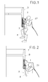
- Figure 1 is a diagrammatic view showing an operator inside a wind turbine deflector who is fitting a seal in a first part of the wind turbine by using a prior art manually operated tool.
- Figure 2 is a diagrammatic view showing an operator inside a wind turbine deflector fitting a seal in a first part of the wind turbine by using the device of the invention;
- Figure 3 is fragmentary enlarged elevation view of one embodiment of a device according to the invention;
- Figure 4 is a sectional view taken along line B-B in fig 5 of one embodiment of the pressing member of the device in fig. 3;
- Figure 5 is an elevation view of the pressing member in fig. 3;
- Figure 6 is a sectional view taken along line A-A in fig. 7 of an eccentric bush; and
- Figure 7 is a top view of the eccentric bush of fig. 6.
- A device for fitting a seal into a seat in a first part of a wind turbine is shown in detail in figure 3 of the drawings. The device has been indicated as a whole with
reference numeral 1 and it is suitable in operations of maintenance or partial or complete replacement of the sealing. - The
device 1 in the embodiment of figure 3 comprises apressing member 2 in the form of a wheel and means 3 for attachment of said pressingmember 2 to a part of the wind turbine as it will be explained further on. - The seal, indicated at 4 in the drawings, has to be fitted into a
seat 5 formed in a first part A of the wind turbine. In the embodiment shown, said first part A corresponds to thebearing 6 of a wind turbine pitch blade mechanism. Thebearing 6 in said pitch blade mechanism is provided with theouter seal 4 and aninner seal 20. The embodiment of thedevice 1 herein described is suitable for fitting theouter seal 4 in thebearing 6. - The
device 1 is attached by saidmeans 3 to a second part B of the wind turbine which, in the embodiment shown, is the ablade root 7 of the wind turbine. - The first part A and the second part B of the wind turbine may be moved to each other. Upon relative rotation between said first and second parts A, B, the
seal 4 is pressed by the pressingmember 2 into theseat 5 of thebearing 6. - The
means 3 for attachment of the pressing member orwheel 2 to the second part B of the wind turbine comprises a metallic, inwardly threadedinsert 8. Theinsert 8 is fitted into ahole 9 formed in said second part B of the wind turbine, that is, theblade root 7.Insert 8 is only needed in the case theblade root 7 is made out of composite materials such as fibre glass, carbon, Kevlar, etc.). Otherwise,insert 8 would not be needed in the case thedevice 1 is to be attached to a steel blade extender (not shown) since a shat for thewheel 2 may be directly threaded in a threaded hole formed therein. - In the embodiment shown in figures, in which the
device 1 is attached to ablade root 7, themeans 3 for attachment of thewheel 2 to saidblade root 7 further includes astud 10 that is threadingly received into theinsert 8. Thestud 10 is a hexagon socket type stud so that it can be suitably screwed in. - An
eccentric bush 11 is mounted around thestud 10 and it is prevented from being rotated by two flat surfaces (not shown) formed on saidstud 10. - A self-locking
nut 12 is screwed in one free end of thestud 10 pushing a lockingwasher 13 provided between theeccentric bush 11 and the self-lockingnut 12. The lockingwasher 13 is provided with a lockingpin 14 that prevents theeccentric bush 11 from being rotated. - Figures 6 and 7 show the above mentioned
eccentric bush 11. Particularly, theeccentric bush 11 has a firstcentral hole 24 for receiving thestud 10 and an offsethole 25 for receiving the lockingpin 14, as shown in figure 7. Figure 6 shows the sectional view of thebush 11 as having afirst portion 26 which abuts theblade root 7 of the wind turbine (second part B) and asecond portion 27, that is smaller in diameter than saidfirst portion 26. In use thissecond portion 27 of theeccentric bush 11 receives aball bearing 15 that comes inserted into thecentral hole 28 of thewheel 2. The pressing member orwheel 2 is rotatably mounted on theblade root 7 of the wind turbine (second part B) by saidball bearing 15 that reduces frictional forces on wheel rotation. - A seger
elastic ring 16 is fitted in arecess 17 in thewheel 2.Ring 16, along with acover 18, prevents thewheel 2 from working their way out of thebearing 15. Thecover 18 is fixed to thewheel 2 by threescrews 19 screwed in corresponding threaded holes 29. - As the
wheel 2 is eccentrictly mounted in the second part B of the wind turbine, the required pressure of thewheel 2 on theseal 4 can be accurately adjusted. - The second part B of the wind turbine, for example blade root, extender root, etc. may have one or more metallic, inwardly threaded
inserts 8 therein for fixing thedevice 1 in one or different positions around 360° on the side surface of said second part B of the wind turbine. - As shown in figure 4, the outer
radial surface 21 of thewheel 2 is shaped so as to have agroove 22. Saidgroove 22 in thewheel 2 has a profile that is shaped complementarily to that of the outer surface of theseal 4. This makes thewheel 2 to be guided by theseal 4 as thewheel 2 is passed thereon. - The
wheel 2 is made out of polyamide (nylon) or any other material suitable to avoid damage on theseal 4 and to be capable of sufficiently press onto saidjoint 4. - For replacing an old
outer seal 4 with anew seal 4 anoperator 23 first removes the old outer seal and places anew seal 4 into theseat 5 formed in the first part A of the wind turbine. - The
operator 23 then attaches thedevice 1 to the blade root 7 (part B) of the wind turbine by screwing thestud 10 in theinsert 8 that is provided inside theblade root 7. Thewheel 2 and theinsert 8 are then placed on thestud 10 with thecorresponding locking pin 14. Lockingnut 12 is then screwed in around thestud 10 thus locking thewheel 2 preventing it from coming off thestud 10. - Once the
device 1 is attached to part B, said second part B, along with thedevice 1, is rotated relative to thebearing 6 of the pitch blade mechanism (part A) of the wind turbine by operating the pitch blade mechanism. As this rotating movement between parts A, B is performed, thewheel 2 presses theseal 4 into theseat 5. In the embodiment shown, advantage of the rotor rotational movement is taken so that thewheel 2 runs over theseal 4 forcing it to be inserted inside theseat 5 provided in the first part A. The blade is rotated by the blade pitch mechanism control of the wind turbine through which movement direction, traveled angle and rotational speed can be set. - The
wheel 2 may be passed onto the outer seal surface in several runs as necessary until the joint 4 has been properly fitted into theseat 5 of thebearing 6. Once theseal 4 has been fitted, thedevice 1 is removed from the second part B of the wind turbine by theoperator 23. - Once the
seal 4 has been properly placed into theseat 5 and ready for operation, thedevice 1 may be removed from the second part B of the wind turbine by unscrewing the lockingnut 12 from thestud 10 and removing thebush 11 along with thewheel 2. A plug (not shown) can be placed to close the inside of theinsert 8 when thedevice 1 is out of the second part B of the wind turbine. The plug protects the inside of theinsert 8 from dirt, corrosion, and other external agents that could damage it when thedevice 1 is not installed.
Claims (12)
- A device (1) for fitting a seal (4) into a seat (5) in a first part (A) of a wind turbine, said device (1) comprising at least one pressing member (2) and means (3) for attachment of said pressing member (2) to a second part (B) of the wind turbine which may have a relative movement with regard to said first part (A) such that upon relative rotation between said first and second parts (A, B), the pressing member (2) of the device (1) presses the seal (4) into the seat (5).
- A device (1) as claimed in claim 1, wherein said first part (A) of the wind turbine is a bearing (6) in a wind turbine pitch blade mechanism.
- A device (1) as claimed in claim 1, wherein said second part (B) of the wind turbine is a blade root (7) of the wind turbine rotor.
- A device (1) as claimed in claim 1, wherein said second part (B) of the wind turbine is an extender root of a wind turbine blade.
- A device (1) as claimed in claim 1, wherein the pressing member (2) is rotatably mounted on said second part (B) of the wind turbine.
- A device (1) as claimed in claim 1 or claim 5, wherein said pressing member (2) is a wheel or roller.
- A device (1) as claimed in claim 5 or claim 6, wherein said pressing member (2) is provided with a groove (22) having a profile shaped complementarily to that of the outer surface of the seal (4).
- A device (1) as claimed in any of the claims 5-7, wherein said pressing member (2) is eccentrictly rotatably mounted to said second part (B) of the wind turbine so that the required pressure on the seal (4) can be adjusted.
- A device (1) as claimed in any of the claims 6-8, wherein said pressing member (2) is made of polyamide.
- A method for fitting a seal (4) into a seat (5) in a first part (A) of a wind turbine, the method comprising the steps of placing a seal (4) into the seat (5) and causing at least a pressing member (2) to press said seal (4) into the seat (5) by causing relative rotation between the first part (A) of the wind turbine and a second part (B) thereof to which said pressing member (2) is attached.
- A method as claimed in claim 12, wherein it further comprises a previous step of attaching said pressing member (2) to said second part (B) of the wind turbine.
- A method as claimed in claim 10 or claim 11, wherein it further comprises a step of removing said pressing member (2) from said second part (B) of the wind turbine.
Priority Applications (11)
| Application Number | Priority Date | Filing Date | Title |
|---|---|---|---|
| EP06123400A EP1925860A1 (en) | 2006-11-02 | 2006-11-02 | Device for fitting a seal |
| US11/606,765 US7987600B2 (en) | 2006-11-02 | 2006-11-30 | Device and method for fitting a seal into a seat in a wind turbine |
| PL07822134T PL2089646T3 (en) | 2006-11-02 | 2007-10-31 | Device for fitting a seal |
| ES07822134T ES2370179T3 (en) | 2006-11-02 | 2007-10-31 | DEVICE FOR MOUNTING A BOARD. |
| JP2009535683A JP2010508470A (en) | 2006-11-02 | 2007-10-31 | Seal mounting device |
| PCT/EP2007/061788 WO2008053027A1 (en) | 2006-11-02 | 2007-10-31 | Device for fitting a seal |
| EP07822134A EP2089646B1 (en) | 2006-11-02 | 2007-10-31 | Device for fitting a seal |
| CNA2007800445484A CN101548119A (en) | 2006-11-02 | 2007-10-31 | Device for fitting a seal |
| CA002667948A CA2667948A1 (en) | 2006-11-02 | 2007-10-31 | Device for fitting a seal |
| AT07822134T ATE518083T1 (en) | 2006-11-02 | 2007-10-31 | DEVICE FOR ATTACHING A SEAL |
| DK07822134.8T DK2089646T3 (en) | 2006-11-02 | 2007-10-31 | Apparatus intended to fit a gasket into a holder in a first part of a wind turbine |
Applications Claiming Priority (1)
| Application Number | Priority Date | Filing Date | Title |
|---|---|---|---|
| EP06123400A EP1925860A1 (en) | 2006-11-02 | 2006-11-02 | Device for fitting a seal |
Publications (1)
| Publication Number | Publication Date |
|---|---|
| EP1925860A1 true EP1925860A1 (en) | 2008-05-28 |
Family
ID=37758876
Family Applications (2)
| Application Number | Title | Priority Date | Filing Date |
|---|---|---|---|
| EP06123400A Withdrawn EP1925860A1 (en) | 2006-11-02 | 2006-11-02 | Device for fitting a seal |
| EP07822134A Active EP2089646B1 (en) | 2006-11-02 | 2007-10-31 | Device for fitting a seal |
Family Applications After (1)
| Application Number | Title | Priority Date | Filing Date |
|---|---|---|---|
| EP07822134A Active EP2089646B1 (en) | 2006-11-02 | 2007-10-31 | Device for fitting a seal |
Country Status (10)
| Country | Link |
|---|---|
| US (1) | US7987600B2 (en) |
| EP (2) | EP1925860A1 (en) |
| JP (1) | JP2010508470A (en) |
| CN (1) | CN101548119A (en) |
| AT (1) | ATE518083T1 (en) |
| CA (1) | CA2667948A1 (en) |
| DK (1) | DK2089646T3 (en) |
| ES (1) | ES2370179T3 (en) |
| PL (1) | PL2089646T3 (en) |
| WO (1) | WO2008053027A1 (en) |
Cited By (4)
| Publication number | Priority date | Publication date | Assignee | Title |
|---|---|---|---|---|
| EP2746609A1 (en) * | 2012-12-19 | 2014-06-25 | IMO Holding GmbH | Anti-corrosion device and bearing assembly equipped with same |
| WO2014094924A1 (en) * | 2012-12-19 | 2014-06-26 | Imo Holding Gmbh | Bearing arrangement comprising a corrosion protection device |
| EP3139033A1 (en) * | 2015-09-07 | 2017-03-08 | Siemens Aktiengesellschaft | Maintenance access to blade bearing of wind turbine |
| US9915245B2 (en) * | 2014-04-17 | 2018-03-13 | Siemens Aktiengesellschaft | Reinforced pitch bearing of a wind turbine |
Families Citing this family (19)
| Publication number | Priority date | Publication date | Assignee | Title |
|---|---|---|---|---|
| US8313289B2 (en) * | 2007-12-07 | 2012-11-20 | United Technologies Corp. | Gas turbine engine systems involving rotor bayonet coverplates and tools for installing such coverplates |
| KR100934965B1 (en) * | 2009-07-17 | 2010-01-06 | 주식회사 신라정밀 | Apparatus for inserting seal in slewing bearing |
| US8043012B2 (en) * | 2009-09-30 | 2011-10-25 | General Electric Company | Seal arrangement and a brush seal for a wind turbine |
| US8174144B2 (en) * | 2010-12-21 | 2012-05-08 | General Electric Company | Bearings having radial half cage |
| US8181326B2 (en) * | 2011-03-10 | 2012-05-22 | General Electric Company | Method and apparatus for installing a seal |
| US8777202B2 (en) * | 2011-05-19 | 2014-07-15 | General Electric Company | Tool for adjusting seal |
| CN103182697B (en) * | 2011-12-30 | 2015-04-29 | 上海英祺精密零件制造有限公司 | Bearing press mounting device |
| CN102825420B (en) * | 2012-09-28 | 2015-03-11 | 南车株洲电力机车研究所有限公司 | Sliding friction sheet replacement method and device of wind driven generator yaw system |
| US9551324B2 (en) | 2013-06-20 | 2017-01-24 | General Electric Company | Pitch bearing assembly with stiffener |
| US9951815B2 (en) | 2013-06-27 | 2018-04-24 | General Electric Company | Pitch bearing assembly with stiffener |
| CN104325274B (en) * | 2013-07-22 | 2016-12-28 | 苏州机翊得自动化设备有限公司 | A kind of VVT sealing member assembles press-fit equipment |
| US9523348B2 (en) | 2013-09-25 | 2016-12-20 | General Electric Company | Rotor blade assembly with shim plate for mitigation pitch bearing loads |
| US9429041B2 (en) | 2014-05-14 | 2016-08-30 | General Electric Company | Turbomachine component displacement apparatus and method of use |
| JP6520670B2 (en) * | 2015-12-04 | 2019-05-29 | トヨタ車体株式会社 | Magazine for sealing member supply and sealing member supply apparatus |
| JP6678556B2 (en) * | 2016-10-27 | 2020-04-08 | 株式会社バルカー | Split seal ring press-fitting jig |
| ES2750877B2 (en) * | 2018-09-26 | 2021-06-11 | Laulagun Bearings S L | TOOL FOR MOUNTING SEALS ON BEARINGS |
| CN109702447B (en) * | 2019-02-20 | 2020-04-07 | 中国船舶科学研究中心(中国船舶重工集团公司第七0二研究所) | Spherical crown type observation window sealing ring replacing device and replacing method |
| US11454219B2 (en) | 2019-05-10 | 2022-09-27 | General Electric Company | Rotor assembly having a pitch bearing with a stiffener ring |
| EP3825545B1 (en) * | 2019-11-21 | 2022-06-01 | Wobben Properties GmbH | Rotor blade, rotor and wind turbine and method |
Citations (4)
| Publication number | Priority date | Publication date | Assignee | Title |
|---|---|---|---|---|
| DE19744275A1 (en) * | 1997-10-07 | 1999-04-08 | Fickenscher & Soehne Gmbh & Co | Device for manually drawing elastic sealing lip into socket of frame |
| JP2002275940A (en) * | 2001-03-15 | 2002-09-25 | Hitachi Constr Mach Co Ltd | Jig for exchanging rotary ring sealing material |
| DE10309383A1 (en) * | 2002-03-04 | 2003-09-18 | Imo Ind Momentenlager Stoll & | Two-part all-weather seal for wind turbine blade root and bearing |
| US20060182634A1 (en) * | 2004-10-29 | 2006-08-17 | Ab Skf | Wind power plant |
Family Cites Families (10)
| Publication number | Priority date | Publication date | Assignee | Title |
|---|---|---|---|---|
| US1159645A (en) * | 1912-02-14 | 1915-11-09 | Alexander T Brown | Type-bar antifriction-bearing. |
| US4274807A (en) * | 1978-07-31 | 1981-06-23 | Kenney Clarence E | Speed control system for a windmill |
| FR2572123B1 (en) | 1984-10-22 | 1988-07-22 | Jaillet Jean | MACHINE FOR POSITIONING THE SEALS |
| JPH0631964U (en) * | 1991-07-22 | 1994-04-26 | 株式会社ムトー | Mesh door netting |
| JPH05196048A (en) * | 1992-01-17 | 1993-08-06 | Mitsubishi Heavy Ind Ltd | Bearing sealing device |
| US6732950B2 (en) * | 2001-01-16 | 2004-05-11 | Rain Bird Corporation | Gear drive sprinkler |
| DE20116649U1 (en) * | 2001-10-10 | 2001-12-06 | Skf Ab | Bearings, especially rolling bearings |
| JP3729779B2 (en) * | 2001-12-21 | 2005-12-21 | 有限会社サン・エンプラ | Screen door screen tensioner |
| JP2003240124A (en) | 2002-02-13 | 2003-08-27 | Hitachi Constr Mach Co Ltd | Seal removing jig for rotary ring |
| BRPI0512835A (en) * | 2004-07-02 | 2008-04-08 | Kunststoff Technik Scherer & T | plastic edge sealing strip and snap head |
-
2006
- 2006-11-02 EP EP06123400A patent/EP1925860A1/en not_active Withdrawn
- 2006-11-30 US US11/606,765 patent/US7987600B2/en active Active
-
2007
- 2007-10-31 PL PL07822134T patent/PL2089646T3/en unknown
- 2007-10-31 ES ES07822134T patent/ES2370179T3/en active Active
- 2007-10-31 CN CNA2007800445484A patent/CN101548119A/en active Pending
- 2007-10-31 DK DK07822134.8T patent/DK2089646T3/en active
- 2007-10-31 AT AT07822134T patent/ATE518083T1/en not_active IP Right Cessation
- 2007-10-31 WO PCT/EP2007/061788 patent/WO2008053027A1/en active Application Filing
- 2007-10-31 EP EP07822134A patent/EP2089646B1/en active Active
- 2007-10-31 CA CA002667948A patent/CA2667948A1/en not_active Abandoned
- 2007-10-31 JP JP2009535683A patent/JP2010508470A/en not_active Ceased
Patent Citations (4)
| Publication number | Priority date | Publication date | Assignee | Title |
|---|---|---|---|---|
| DE19744275A1 (en) * | 1997-10-07 | 1999-04-08 | Fickenscher & Soehne Gmbh & Co | Device for manually drawing elastic sealing lip into socket of frame |
| JP2002275940A (en) * | 2001-03-15 | 2002-09-25 | Hitachi Constr Mach Co Ltd | Jig for exchanging rotary ring sealing material |
| DE10309383A1 (en) * | 2002-03-04 | 2003-09-18 | Imo Ind Momentenlager Stoll & | Two-part all-weather seal for wind turbine blade root and bearing |
| US20060182634A1 (en) * | 2004-10-29 | 2006-08-17 | Ab Skf | Wind power plant |
Cited By (6)
| Publication number | Priority date | Publication date | Assignee | Title |
|---|---|---|---|---|
| EP2746609A1 (en) * | 2012-12-19 | 2014-06-25 | IMO Holding GmbH | Anti-corrosion device and bearing assembly equipped with same |
| WO2014094924A1 (en) * | 2012-12-19 | 2014-06-26 | Imo Holding Gmbh | Bearing arrangement comprising a corrosion protection device |
| US10072703B2 (en) | 2012-12-19 | 2018-09-11 | Imo Holding Gmbh | Bearing arrangement comprising a corrosion protection device |
| US9915245B2 (en) * | 2014-04-17 | 2018-03-13 | Siemens Aktiengesellschaft | Reinforced pitch bearing of a wind turbine |
| EP3139033A1 (en) * | 2015-09-07 | 2017-03-08 | Siemens Aktiengesellschaft | Maintenance access to blade bearing of wind turbine |
| US10364793B2 (en) | 2015-09-07 | 2019-07-30 | Siemens Gamesa Renewable Energy A/S | Maintenance access to blade bearing |
Also Published As
| Publication number | Publication date |
|---|---|
| DK2089646T3 (en) | 2011-11-14 |
| WO2008053027A1 (en) | 2008-05-08 |
| EP2089646A1 (en) | 2009-08-19 |
| CN101548119A (en) | 2009-09-30 |
| EP2089646B1 (en) | 2011-07-27 |
| PL2089646T3 (en) | 2011-12-30 |
| ATE518083T1 (en) | 2011-08-15 |
| US20080104821A1 (en) | 2008-05-08 |
| CA2667948A1 (en) | 2008-05-08 |
| US7987600B2 (en) | 2011-08-02 |
| JP2010508470A (en) | 2010-03-18 |
| ES2370179T3 (en) | 2011-12-13 |
Similar Documents
| Publication | Publication Date | Title |
|---|---|---|
| EP2089646B1 (en) | Device for fitting a seal | |
| CN102734060B (en) | Pitch bearing | |
| EP2497606B1 (en) | Apparatus for installing a seal | |
| US7422419B2 (en) | Propeller blade retention system | |
| US9234332B2 (en) | Mechanical system for connecting a wearing part and a support thereof, and method for implementing said system | |
| WO2001048376A2 (en) | Plain bearing and wind energy unit with said bearing | |
| US10823137B2 (en) | Methods and systems for disassembling a pitch bearing from a wind turbine hub | |
| EP2000404B1 (en) | Propeller blade retention system with tapered roller bearing cartridge assemblies | |
| EP3639969A1 (en) | Method and tool for reconditioning a damaged thread | |
| EP2535559A2 (en) | Pitching system for segmented wind turbine blade | |
| US20210231108A1 (en) | Method for repairing a leading edge of wind turbine blade | |
| DE102019212629A1 (en) | Rotor bearing for a wind turbine and wind turbine | |
| EP3825545B1 (en) | Rotor blade, rotor and wind turbine and method | |
| GB2442147A (en) | Method of assembling a propeller blade retention assembly | |
| US10260340B2 (en) | Cutter assembly with cutter device and method of assembling | |
| CN219827036U (en) | Dismounting device for rear sealing ring of main shaft on tower of wind generating set | |
| CN218407553U (en) | Steam turbine and steam turbine set with damping structure | |
| CN210174532U (en) | A wheel hub assembly for fork truck transaxle | |
| CN216077997U (en) | Positioning idler wheel and positioning device | |
| CN209867894U (en) | Fastening bolt repairing device | |
| CN216895365U (en) | Self-aligning roller bearing | |
| CN208633980U (en) | A kind of fan paddle-changing system | |
| US10415383B2 (en) | Cutter assembly with rolling elements and method of disassembling | |
| CN111546268A (en) | Special device for maintenance and installation of heavy engine crankshaft oil seal | |
| JP2014159828A (en) | Bearing structure |
Legal Events
| Date | Code | Title | Description |
|---|---|---|---|
| PUAI | Public reference made under article 153(3) epc to a published international application that has entered the european phase |
Free format text: ORIGINAL CODE: 0009012 |
|
| AK | Designated contracting states |
Kind code of ref document: A1 Designated state(s): AT BE BG CH CY CZ DE DK EE ES FI FR GB GR HU IE IS IT LI LT LU LV MC NL PL PT RO SE SI SK TR |
|
| AX | Request for extension of the european patent |
Extension state: AL BA HR MK RS |
|
| AKX | Designation fees paid | ||
| REG | Reference to a national code |
Ref country code: DE Ref legal event code: 8566 |
|
| STAA | Information on the status of an ep patent application or granted ep patent |
Free format text: STATUS: THE APPLICATION IS DEEMED TO BE WITHDRAWN |
|
| 18D | Application deemed to be withdrawn |
Effective date: 20081129 |