EP3139034A1 - Removal of a front top sliding pad of a yaw bearing of a wind turbine - Google Patents
Removal of a front top sliding pad of a yaw bearing of a wind turbine Download PDFInfo
- Publication number
- EP3139034A1 EP3139034A1 EP16170809.4A EP16170809A EP3139034A1 EP 3139034 A1 EP3139034 A1 EP 3139034A1 EP 16170809 A EP16170809 A EP 16170809A EP 3139034 A1 EP3139034 A1 EP 3139034A1
- Authority
- EP
- European Patent Office
- Prior art keywords
- bearing component
- bearing
- top sliding
- lifting wedge
- yaw
- Prior art date
- Legal status (The legal status is an assumption and is not a legal conclusion. Google has not performed a legal analysis and makes no representation as to the accuracy of the status listed.)
- Granted
Links
Images

Classifications
-
- F—MECHANICAL ENGINEERING; LIGHTING; HEATING; WEAPONS; BLASTING
- F03—MACHINES OR ENGINES FOR LIQUIDS; WIND, SPRING, OR WEIGHT MOTORS; PRODUCING MECHANICAL POWER OR A REACTIVE PROPULSIVE THRUST, NOT OTHERWISE PROVIDED FOR
- F03D—WIND MOTORS
- F03D80/00—Details, components or accessories not provided for in groups F03D1/00 - F03D17/00
- F03D80/50—Maintenance or repair
-
- F—MECHANICAL ENGINEERING; LIGHTING; HEATING; WEAPONS; BLASTING
- F03—MACHINES OR ENGINES FOR LIQUIDS; WIND, SPRING, OR WEIGHT MOTORS; PRODUCING MECHANICAL POWER OR A REACTIVE PROPULSIVE THRUST, NOT OTHERWISE PROVIDED FOR
- F03D—WIND MOTORS
- F03D80/00—Details, components or accessories not provided for in groups F03D1/00 - F03D17/00
- F03D80/70—Bearing or lubricating arrangements
-
- F—MECHANICAL ENGINEERING; LIGHTING; HEATING; WEAPONS; BLASTING
- F16—ENGINEERING ELEMENTS AND UNITS; GENERAL MEASURES FOR PRODUCING AND MAINTAINING EFFECTIVE FUNCTIONING OF MACHINES OR INSTALLATIONS; THERMAL INSULATION IN GENERAL
- F16C—SHAFTS; FLEXIBLE SHAFTS; ELEMENTS OR CRANKSHAFT MECHANISMS; ROTARY BODIES OTHER THAN GEARING ELEMENTS; BEARINGS
- F16C35/00—Rigid support of bearing units; Housings, e.g. caps, covers
- F16C35/02—Rigid support of bearing units; Housings, e.g. caps, covers in the case of sliding-contact bearings
-
- F—MECHANICAL ENGINEERING; LIGHTING; HEATING; WEAPONS; BLASTING
- F05—INDEXING SCHEMES RELATING TO ENGINES OR PUMPS IN VARIOUS SUBCLASSES OF CLASSES F01-F04
- F05B—INDEXING SCHEME RELATING TO WIND, SPRING, WEIGHT, INERTIA OR LIKE MOTORS, TO MACHINES OR ENGINES FOR LIQUIDS COVERED BY SUBCLASSES F03B, F03D AND F03G
- F05B2230/00—Manufacture
- F05B2230/60—Assembly methods
- F05B2230/604—Assembly methods using positioning or alignment devices for aligning or centering, e.g. pins
- F05B2230/608—Assembly methods using positioning or alignment devices for aligning or centering, e.g. pins for adjusting the position or the alignment, e.g. wedges or excenters
-
- F—MECHANICAL ENGINEERING; LIGHTING; HEATING; WEAPONS; BLASTING
- F05—INDEXING SCHEMES RELATING TO ENGINES OR PUMPS IN VARIOUS SUBCLASSES OF CLASSES F01-F04
- F05B—INDEXING SCHEME RELATING TO WIND, SPRING, WEIGHT, INERTIA OR LIKE MOTORS, TO MACHINES OR ENGINES FOR LIQUIDS COVERED BY SUBCLASSES F03B, F03D AND F03G
- F05B2230/00—Manufacture
- F05B2230/70—Disassembly methods
-
- F—MECHANICAL ENGINEERING; LIGHTING; HEATING; WEAPONS; BLASTING
- F05—INDEXING SCHEMES RELATING TO ENGINES OR PUMPS IN VARIOUS SUBCLASSES OF CLASSES F01-F04
- F05B—INDEXING SCHEME RELATING TO WIND, SPRING, WEIGHT, INERTIA OR LIKE MOTORS, TO MACHINES OR ENGINES FOR LIQUIDS COVERED BY SUBCLASSES F03B, F03D AND F03G
- F05B2230/00—Manufacture
- F05B2230/80—Repairing, retrofitting or upgrading methods
-
- F—MECHANICAL ENGINEERING; LIGHTING; HEATING; WEAPONS; BLASTING
- F05—INDEXING SCHEMES RELATING TO ENGINES OR PUMPS IN VARIOUS SUBCLASSES OF CLASSES F01-F04
- F05B—INDEXING SCHEME RELATING TO WIND, SPRING, WEIGHT, INERTIA OR LIKE MOTORS, TO MACHINES OR ENGINES FOR LIQUIDS COVERED BY SUBCLASSES F03B, F03D AND F03G
- F05B2250/00—Geometry
- F05B2250/10—Geometry two-dimensional
- F05B2250/14—Geometry two-dimensional elliptical
- F05B2250/141—Geometry two-dimensional elliptical circular
-
- F—MECHANICAL ENGINEERING; LIGHTING; HEATING; WEAPONS; BLASTING
- F05—INDEXING SCHEMES RELATING TO ENGINES OR PUMPS IN VARIOUS SUBCLASSES OF CLASSES F01-F04
- F05B—INDEXING SCHEME RELATING TO WIND, SPRING, WEIGHT, INERTIA OR LIKE MOTORS, TO MACHINES OR ENGINES FOR LIQUIDS COVERED BY SUBCLASSES F03B, F03D AND F03G
- F05B2250/00—Geometry
- F05B2250/20—Geometry three-dimensional
- F05B2250/29—Geometry three-dimensional machined; miscellaneous
- F05B2250/292—Geometry three-dimensional machined; miscellaneous tapered
-
- F—MECHANICAL ENGINEERING; LIGHTING; HEATING; WEAPONS; BLASTING
- F05—INDEXING SCHEMES RELATING TO ENGINES OR PUMPS IN VARIOUS SUBCLASSES OF CLASSES F01-F04
- F05B—INDEXING SCHEME RELATING TO WIND, SPRING, WEIGHT, INERTIA OR LIKE MOTORS, TO MACHINES OR ENGINES FOR LIQUIDS COVERED BY SUBCLASSES F03B, F03D AND F03G
- F05B2260/00—Function
- F05B2260/30—Retaining components in desired mutual position
-
- F—MECHANICAL ENGINEERING; LIGHTING; HEATING; WEAPONS; BLASTING
- F16—ENGINEERING ELEMENTS AND UNITS; GENERAL MEASURES FOR PRODUCING AND MAINTAINING EFFECTIVE FUNCTIONING OF MACHINES OR INSTALLATIONS; THERMAL INSULATION IN GENERAL
- F16C—SHAFTS; FLEXIBLE SHAFTS; ELEMENTS OR CRANKSHAFT MECHANISMS; ROTARY BODIES OTHER THAN GEARING ELEMENTS; BEARINGS
- F16C2237/00—Repair or replacement
-
- F—MECHANICAL ENGINEERING; LIGHTING; HEATING; WEAPONS; BLASTING
- F16—ENGINEERING ELEMENTS AND UNITS; GENERAL MEASURES FOR PRODUCING AND MAINTAINING EFFECTIVE FUNCTIONING OF MACHINES OR INSTALLATIONS; THERMAL INSULATION IN GENERAL
- F16C—SHAFTS; FLEXIBLE SHAFTS; ELEMENTS OR CRANKSHAFT MECHANISMS; ROTARY BODIES OTHER THAN GEARING ELEMENTS; BEARINGS
- F16C2300/00—Application independent of particular apparatuses
- F16C2300/10—Application independent of particular apparatuses related to size
- F16C2300/14—Large applications, e.g. bearings having an inner diameter exceeding 500 mm
-
- F—MECHANICAL ENGINEERING; LIGHTING; HEATING; WEAPONS; BLASTING
- F16—ENGINEERING ELEMENTS AND UNITS; GENERAL MEASURES FOR PRODUCING AND MAINTAINING EFFECTIVE FUNCTIONING OF MACHINES OR INSTALLATIONS; THERMAL INSULATION IN GENERAL
- F16C—SHAFTS; FLEXIBLE SHAFTS; ELEMENTS OR CRANKSHAFT MECHANISMS; ROTARY BODIES OTHER THAN GEARING ELEMENTS; BEARINGS
- F16C2360/00—Engines or pumps
- F16C2360/31—Wind motors
-
- Y—GENERAL TAGGING OF NEW TECHNOLOGICAL DEVELOPMENTS; GENERAL TAGGING OF CROSS-SECTIONAL TECHNOLOGIES SPANNING OVER SEVERAL SECTIONS OF THE IPC; TECHNICAL SUBJECTS COVERED BY FORMER USPC CROSS-REFERENCE ART COLLECTIONS [XRACs] AND DIGESTS
- Y02—TECHNOLOGIES OR APPLICATIONS FOR MITIGATION OR ADAPTATION AGAINST CLIMATE CHANGE
- Y02E—REDUCTION OF GREENHOUSE GAS [GHG] EMISSIONS, RELATED TO ENERGY GENERATION, TRANSMISSION OR DISTRIBUTION
- Y02E10/00—Energy generation through renewable energy sources
- Y02E10/70—Wind energy
- Y02E10/72—Wind turbines with rotation axis in wind direction
-
- Y—GENERAL TAGGING OF NEW TECHNOLOGICAL DEVELOPMENTS; GENERAL TAGGING OF CROSS-SECTIONAL TECHNOLOGIES SPANNING OVER SEVERAL SECTIONS OF THE IPC; TECHNICAL SUBJECTS COVERED BY FORMER USPC CROSS-REFERENCE ART COLLECTIONS [XRACs] AND DIGESTS
- Y02—TECHNOLOGIES OR APPLICATIONS FOR MITIGATION OR ADAPTATION AGAINST CLIMATE CHANGE
- Y02P—CLIMATE CHANGE MITIGATION TECHNOLOGIES IN THE PRODUCTION OR PROCESSING OF GOODS
- Y02P70/00—Climate change mitigation technologies in the production process for final industrial or consumer products
- Y02P70/50—Manufacturing or production processes characterised by the final manufactured product
Abstract
Description
- The present invention relates to a method of removing a front top sliding pad of a yaw bearing of a wind turbine. Furthermore, the invention relates to a method of exchanging such a front top sliding pad. Finally, the invention relates to a lifting wedge for carrying out the removal and exchange of such a front top sliding pad.
- A modern horizontal axis wind turbine typically comprises a tower, a nacelle, a hub and a rotor with one or several rotor blades. The nacelle, the hub and the rotor form together an ensemble of the wind turbine which typically can be rotated about an axis which is substantially vertical. This rotational movement is referred to as a yawing movement. Consequently, the axis about which the ensemble comprising the nacelle, the hub and the rotor rotates is referred to as the yaw axis. The center of gravity of the ensemble comprising the nacelle, the hub and the rotor may be on the yaw axis or in close proximity of the yaw axis. Alternatively, the center of gravity may also be considerably separated from the yaw axis. Whether the first or the last alternative is the case depends a lot on the design and the type of the wind turbine.
- Especially for wind turbines which feature a center of gravity which is at a certain distance from the yaw axis, large forces on the top sliding pads of the yaw bearing apply. These large forces particularly act on the front of the yaw bearing. The front of the yaw bearing refers to the part which is directed towards the hub of the wind turbine. Because of these large forces acting on the top sliding pads in the front of the yaw bearing, uneven wear occurs on the front top sliding pads.
- A change of the front top sliding pads is extremely expensive and complex. According to the state of the art a lifting device such as a lifting crane lifts the ensemble comprising the nacelle, the hub and the rotor by a few millimeters or centimeters such that the front top sliding pads can be exchanged. However, using such a lifting crane is expensive and difficult, particularly for wind turbines which are difficult to access. Examples for wind turbines which are difficult to access are onshore wind turbines in mountainous regions or offshore wind turbines.
- Thus, there exists the desire to provide a concept which facilitates removing and exchanging of the front top sliding pads of a yaw bearing of a wind turbine.
- This objective is solved by the independent claims. Advantageous modifications and developments are described in the dependent claims.
- According to the invention, there is provided a method of removing a front top sliding pad of a yaw bearing of a wind turbine, wherein the wind turbine comprises a nacelle and a rotor. The rotor features a substantially horizontal rotor axis. The wind turbine also comprises a hub with a plurality of rotor blades. The yaw bearing connects the nacelle with a tower of the wind turbine, wherein the yaw bearing enables a rotational movement of the nacelle about a substantially vertical yaw axis. The yaw bearing comprises a first bearing component which is rigidly connected to the nacelle, and a second bearing component which is rigidly connected to the tower. The yaw bearing comprises axial adjustments to ensure that a pre-determined distance between the first bearing component and the second bearing component is maintained. The first bearing component comprises a front part, which is oriented towards the hub, and a rear part, which is oriented away from the hub. Finally, a plurality of front top sliding pads and a plurality of rear top sliding pads are attached to the first bearing component, wherein the front top sliding pads refer to top sliding pads attached to the front part of the first bearing component; and the rear top sliding pads refer to top sliding pads attached the rear part of the first bearing component.
- The method comprises the following steps:
- loosening the axial adjustments of the yaw bearing such that the rotor of the wind turbine is tilted and a space in the rear part of the first bearing component is generated between the first bearing component and the second bearing component;
- inserting a lifting wedge at the rear part of the first bearing component into the space between the first bearing component and the second bearing component which is generated by the tilt of the rotor;
- rotating the first bearing component, wherein the front part of the first bearing component slides onto the lifting wedge, thus the front part of the first bearing component is lifted with regard to the second bearing component; and
- removing the front top sliding pad by benefitting of the space being generated due to the lift of the front part of the first bearing component relative to the second bearing component.
- The invention is also related to a method of replacing a front top sliding pad of a yaw bearing of a wind turbine. Therefore, the above mentioned method steps are complemented by the step of inserting another front top sliding pad, after having removed the existing front top sliding pad, into the location from which the front top sliding pad has been removed.
- The invention furthermore relates to a lifting wedge for a yaw bearing of a wind turbine. The lifting wedge comprises a thickness, a radial extension, a circumferential extension and circumferential ends. The lifting wedge furthermore comprises an upper surface, which is arranged and prepared to be in contact with a first bearing component of the yaw bearing; and a lower surface, which is arranged and prepared to be in contact with a second bearing component of the yaw bearing. It is essential that the thickness of the lifting wedge diminishes towards at least one of its circumferential ends.
- The considerable advantage of such a lifting wedge and the use thereof for yaw bearings is that the use of a heavy and powerful lifting crane for lifting the ensemble comprising the hub, the nacelle and the rotor is entirely eliminated. This obviously saves considerable material and personal efforts.
- The inventors have realized that by inserting the lifting wedge, the first bearing component can be slit onto the lifting wedge. By subsequent rotation of the first bearing component, the first bearing component can be pushed and lifted upwards. This enables to slightly lift the first bearing component with regard to the second bearing component such that the front top sliding pads can be removed easily.
- The inclination of the upper surface of the lifting wedge has to be optimized with regard to the specific sliding bearing for which it is foreseen. In an exemplary embodiment, the upper surface of the lifting wedge is inclined with regard to the lower surface of the lifting wedge in a range between 0.1 and 1 degree in the region of diminishing thickness of the lifting wedge. Note that in the context of this patent application, the upper surface of the lifting wedge is referred to as the surface which is arranged and prepared to be in contact with the first bearing component. Likewise, the lower surface of the lifting wedge is in the context of this patent application referred to the surface of the lifting wedge which is arranged and prepared to be in contact with the second bearing component.
- Note that it is necessary to loosen the axial adjustments, which are referred to as the bottom sliding shoes in some embodiments, at least in the rear of the wind turbine in order to insert the lifting wedge between the first and the second bearing component. In this context, the "rear" of the wind turbine refers to the part which is directed away from the hub of the wind turbine with the rotor blades. Loosening the axial adjustments results in a tilt of the nacelle, which provides for the necessary space between the first bearing component and the second bearing component in the back of the yaw bearing for inserting the lifting wedge. Preferably, the axial adjustments are not only loosened in the rear, but at various or all circumferential positions of the yaw bearing.
- Also note that as the gravitational force of the first bearing component acts on the top sliding pad, it can also be said that the first bearing component refers to the upper bearing component, while the second bearing component refers to the lower bearing component. The range of inclination which is exemplarily between 0.1 and 1 degree has been proven to be a preferred range. Note that the inclination is relatively little pronounced which is due to the fact that, on the one hand, it has to be ensured that the first bearing component is lifted safely and securely and, on the other hand, even a small lift of the first bearing component with regard to the second bearing component is in most cases sufficient in order to remove a worn top sliding pad. An advantage of a relatively small rate of inclination, such as the exemplarily given range of 0.1 to 1 degree, is the avoidance of high edge loads to the lifting wedge. These loads could otherwise add damage to the lifting wedge.
- Alternatively, a higher rate of inclination, i.e. an angle exceeding 1 degree, could be a beneficial option if, for instance, space for inserting the lifting wedge in the bearing is limited.
- In an advantageous embodiment, the upper surface of the lifting wedge comprises a thermoplastic polymer resin, in particular polyethylene terephthalate (PET). This material has the advantage that it provides for a relatively low friction between the upper surface of the lifting wedge and the first bearing component. Other options for the upper surface of the lifting wedge include polyether ether ketone (PEEK), a colorless organic thermoplastic polymer of the polyaryletherketone (PAEK) family, or other high compression resistant polymers. Even metals with the properties of providing a relatively low friction between the upper surface of the lifting wedge and the first bearing component could represent a suitable material choice for the upper surface of the lifting wedge.
- In order to further reduce the friction between the upper surface of the lifting wedge and the first bearing component a lubricant such as grease for example may favorably be provided between these two contact surfaces.
- It has to be ensured that the lifting wedge is kept in place after insertion. In other words, it has to be ensured that the lifting wedge does not move and slide away from the position where it has been inserted during rotation of the first bearing component. Thus, generally speaking, the lifting wedge shall comprise attachment means for fixing the lifting wedge to the second bearing component.
- One example for a suitable attachment means are screws or bolts by which the lifting wedge can be firmly attached to the second bearing component and can be detached after removal of the top sliding pads.
- Another example for a suitable attachment means are the provision of teeth at the lifting wedge. The teeth are designed such that they match with corresponding recesses at the second bearing component. The provision of a lifting wedge with teeth is a preferred solution as time and efforts to attach and detach screws or bolts is saved, while still ensuring a strong and reliable attachment of the lifting wedge with the second bearing component during rotation of the two bearing components relative to each other after insertion of the lifting wedge.
- Both attachment means (screws/ bolts and teeth) can also be combined with each other, i.e. a toothed lifting wedge may also be (detachably) screwed to the second bearing component.
- The lower surface of the lifting wedge may exemplarily feature a friction which is higher than the friction between the upper surface of the lifting wedge and the first bearing component. A preferred choice of material for the lower surface of the lifting wedge is metalized steel. Note that it may be sufficient to provide a part of the lower surface of the lifting wedge with steel. A configuration which has been proven to be advantageous in practice is to provide the core of the lifting wedge by steel and to cover the upper surface of the steel core and the sites of the lifting wedge with PET material.
- The lifting wedge as described above is preferably used for a sliding yaw bearing of a wind turbine. In this case, the second bearing component may be referred to as the yaw ring of the yaw bearing and the first bearing component may be referred to as the bedframe of the yaw bearing.
- Embodiments of the invention are now described, by way of example only, with reference to the accompanying drawings, of which:
- Figure 1
- shows a wind turbine;
- Figure 2
- shows a cross-sectional view of a part of a yaw bearing of a wind turbine;
- Figure 3
- shows the status of a yaw bearing prior to applying the inventive method of removing the front top sliding pad;
- Figure 4
- shows the status of the yaw bearing after loosening the axial adjustments and inserting a lifting wedge;
- Figure 5
- shows the status of the yaw bearing after rotating the first bearing component of the yaw bearing assuming that all axial adjustments have been loosened;
- Figure 6
- shows the status of the yaw bearing after rotating the first bearing component of the yaw bearing assuming that only the axial adjustments at the rear part of the first bearing component have been loosened;
- Figure 7
- shows a side view of a part of a lifting wedge;
- Figure 8
- shows a top view of the lifting wedge of
Figure 7 ; - Figure 9
- shows a perspective view of the lifting wedge of
Figure 7 ; and - Figure 10
- shows a perspective view of a part of the lower surface of another embodiment of a lifting wedge.
- The illustration in the drawings is in schematic form. It is noted that in different figures, similar or identical elements are provided with the same reference signs.
-
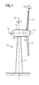
Figure 1 schematically illustrates a horizontal-axis wind turbine 10. Thewind turbine 10 comprises atower 11. At the top of thetower 11, anacelle 12 is mounted. Thenacelle 12 is rotatable connected with thetower 11 via ayaw bearing 20. Theyaw bearing 20 enables a rotational movement of thenacelle 12 about a yaw axis 18, wherein the yaw axis 18 is orientated substantially vertically. In the context of this patent application, the wording "substantially vertical" includes deviations up to twenty degrees, in particular up to ten degrees, with regard to a perfectly vertical orientation. - A
hub 13 is rotatable connected to thenacelle 12 via a main bearing. Thehub 13 is a part of the so-called rotor which transfers rotational energy from thehub 13 to agenerator 15 of thewind turbine 10. A plurality ofrotor blades 17 are attached to thehub 13 in order to harvest the energy from the wind. Therotor blades 17 are mounted pivotable with regard to thehub 13, i.e. therotor blades 17 can be pivoted about arespective pitch axis 16. - The rotor comprises a
rotor axis 14 which is to be understood as the rotational axis of the rotor. Therotor axis 14 is orientated substantially horizontal. In the context of this patent application, the wording "substantially horizontal" includes deviations up to twenty degrees, in particular up to ten degrees, with regard to a perfectly horizontal orientation. It is, for example, common practice to deliberately tilt the rotor axis by a few degrees towards the rear in order to avoid collision of therotor blades 17 of the wind turbine with thetower 11. - The
generator 15 is accommodated within thenacelle 12. If the rotor is directly connected to thegenerator 15, the wind turbine is referred to as a direct-drive, gearless wind turbine. If the rotor is connected to thegenerator 15 via a gear-box, the wind turbine is referred to as geared wind turbine. -
Figure 2 shows a cross-sectional view of a part of a yaw bearing 20 of a wind turbine. This yaw bearing 20 is an example of a sliding bearing for which the inventive lifting wedge can be used. Theyaw bearing 20 comprises afirst bearing component 21 which in the example ofFigure 1 is also referred to as a bedframe. Theyaw bearing 20 also comprises asecond bearing component 22 which in the example ofFigure 1 is represented by a yaw ring of the yaw bearing. Thefirst bearing component 21 is located above thesecond bearing component 22. As a consequence, thefirst bearing component 21 exerts and applies its mass, i.e. its gravitational force, on thesecond bearing component 22. However, it does not only apply its gravitational force and load on thesecond bearing component 22, but in particular on the top slidingpads 23 which is squeezed between thefirst bearing component 21 and thesecond bearing component 22. In the case of modern type wind turbines of the multi mega watt class, several tons up to one hundred tons and more are placed upon the top slidingpads 23. Over the years and after many rotational movements between the first 21 andsecond bearing component 22 wear occurs for the top slidingpads 23. -
Figure 2 also shows further components of the yaw bearing such as theradial sliding pad 24 which is secured by aradial block 241 and abottom sliding pad 25 which is secured by theyaw clamp 251. Thesecond bearing component 22 is connected to atower top flange 111, which is the top part of the tower. -
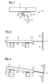
Figures 3 to 6 illustrate the inventive method to remove a front top slidingpad 231 of a yaw bearing of a wind turbine. - A
first bearing component 21, asecond bearing component 22, and two top slidingpads Figures 3 to 6 . Thefirst bearing component 21 comprises afront part 211, which is oriented towards thehub 13 of the wind turbine, and arear part 212, which is oriented away from thehub 13. Thesecond bearing component 22 is directly connected to thetower 11. - Both top sliding
pads first bearing component 21. The top sliding pad which is attached to thefront part 211 of thefirst bearing component 21 is referred to as the front top slidingpad 231. Likewise, the top sliding pad which is attached to therear part 212 of thefirst bearing component 21 is referred to as the reartop sliding pad 232. - Due to the weight of the rotor of the wind turbine, more gravitational force acts on the front top sliding pad compared to the rear top sliding pad. As a consequence, the front top sliding pad is generally more worn than the rear top sliding pad.
- In the first step of the inventive method, the axial adjustments of the yaw bearing are loosened such that the rotor of the wind turbine is tilted and a space in the
rear part 212 of thefirst bearing component 21 is generated between thefirst bearing component 21 and thesecond bearing component 22. The tilt of the rotor after loosening the axial adjustment means is caused because the center of gravity of the rotor is between the front top slidingpad 231 and thehub 13. In other words, the rotor is tilted forwardly after loosening the axial adjustments due to the heavy weight of the hub with the rotor blades. - The axial adjustments can, for instance, be concretely realized by yaw clamps 251 as illustrated in
Figure 2 . Other ways of ensuring the maintenance of a pre-determined distance between thefirst bearing component 21 and thesecond bearing component 22, i.e. other ways of ensuring that the rotor does not tilt forwardly during operation of the wind turbine, are possible, too. - After generation of the space between both bearing
components rear part 212 of the first bearing component, a liftingwedge 30 is inserted into this space. Note that the shape and placement of the liftingwedge 30 are not precisely drawn inFigure 4 , as the purpose ofFigures 3 to 6 is the illustration of the basic principle of the inventive method. More realistic embodiments of the liftingwedge 30 are disclosed inFigures 8 to 10 . - After insertion of the lifting
wedge 30, thefirst bearing component 21, is rotated. This rotation is carried out about the axis of rotational symmetry of thefirst bearing component 21. This axis of rotation is substantially vertical. As a consequence of the rotation of thefirst bearing component 21, thefront part 211 of thefirst bearing component 21 slides onto the liftingwedge 30. Thus, thefront part 211 of thefirst bearing component 21 is lifted with regard to thesecond bearing component 22. In the example as shown inFigure 6 , the first bearing component 21 - and thus also the nacelle (not shown inFigures 3 to 6 ), the rotor and thehub 13 with the rotor blades 16 - is rotated about approximately one hundred eighty degrees. - After completion of the rotational movement, the
front part 211 of thefirst bearing component 21 and the front top slidingpad 231 which is attached to thefirst bearing component 21 are lifted and are located in proximity to the liftingwedge 30. - By benefitting of the space being generated due to the lift of the
front part 211 of thefirst bearing component 21 relative to thesecond bearing component 22, the front top slidingpad 231 can then be accessed easily and removed. - Note that
Figure 5 illustrates a first alternative, wherein all axial adjustments, in particular both the axial adjustments which are situated at thefront part 211 of thefirst bearing component 21 and the axial adjustments which are situated at therear part 212 of thefirst bearing component 21, are loosened. As a consequence, after rotation of thefirst bearing component 21, also therear part 212 of thefirst bearing component 21 is lifted due to the weight of thehub 13 with therotor blades 16, which tends to tilt the rotor forwardly. -
Figure 6 illustrates a second alternative, wherein only the axial adjustments which are situated at thefront part 211 of the first bearing component are loosened. Thus, therear part 212 of thefirst bearing component 21 remains in close proximity to the second bearing component after rotation of thefirst bearing component 21. Consequently, the rotor is tilted upwardly after rotation. -
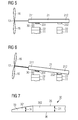
Figure 7 shows a side view of a part of the liftingwedge 30. Thefirst section 301 and a part of thesecond section 302 are illustrated. It can be seen that the thickness of the liftingwedge 30 starts with a specific value at thecircumferential end 33 and increases until it reaches thesecond section 302. In other words, thethickness 34 of the liftingwedge 30 is always higher in thesecond section 302 compared to thethickness 34 of the liftingwedge 30 in thefirst section 301. As an example, the thickness may increase from 5 mm (millimeter) at thecircumferential end 33 until 8.5 mm in thesecond section 302. An example of the circumferential extension of thefirst section 301 is 650 mm. In other words, this is the distance of the lifting wedge where the first bearing component slides upwards and is lifted until it reaches thesecond section 302 of the lifting wedge where the distance of the first and second bearing component remains constant. -
Figure 8 , which shows a top view on theupper surface 35 of the liftingwedge 30 illustrates theradial extension 31 and thecircumferential extension 32 of the liftingwedge 30. Theradial extension 31 is constant in all circumferential positions of the liftingwedge 30. Thecircumferential extension 32 can either be measured at the inner edge or at the outer edge of the liftingwedge 30. The liftingwedge 30 can be characterized by two circumferential ends 33, one on the top part of the drawing ofFigure 8 and one on the right part ofFigure 8 . -
Figure 8 also shows a virtual division of the liftingwedge 30 into three sections: Afirst section 301, asecond section 302 and athird section 303. The middle section, i.e. thesecond section 302, is characterized by a constant thickness. In contrast, thefirst section 301 and thethird section 303 have diminishing thickness towards the circumferential ends 33. -
Figure 9 shows a perspective view on thelower surface 36 of the liftingwedge 30. The inner rim of theupper surface 35 is visible as well. Additionally,Figure 9 illustrates the teeth which are located below thelower surface 36 and which serve to firmly attach and to fix the liftingwedge 30 to thesecond bearing component 22. - Finally,
Figure 10 shows a possible configuration regarding the material choice of the lifting wedge. It has been proven to be advantageous to provide a high friction at thelower surface 36 which may for example be realized by metalized steel. This metalized steel forms the core of the liftingwedge 30. This core is surrounded by a PET-material which provides and realizes a smaller friction. In other words, theupper surface 35, the side parts and even parts of thelower surface 36 are made of PET material. - Note, however, that in practice a lifting wedge with an upper surface such as in
Figure 10 is advantageously combined with a teethed outer rim such as illustrated inFigure 9 in order to reliably ensure that the lifting wedge does not move during rotation of the second bearing component relative to the first bearing component. - Although the present invention has been described in detail with reference to the preferred embodiment, it is to be understood that the present invention is not limited by the disclosed examples, and that numerous additional modifications and variations could be made thereto by a person skilled in the art without departing from the scope of the invention.
- It should be noted that the use of "a" or "an" throughout this application does not exclude a plurality, and "comprising" does not exclude other steps or elements. Also elements described in association with different embodiments may be combined. It should also be noted that reference signs in the claims should not be construed as limiting the scope of the claims.
Claims (11)
- Method of removing a front top sliding pad (231) of a yaw bearing (20) of a wind turbine (10),
wherein- the wind turbine (10) comprises a nacelle (12) and a rotor with a substantially horizontal rotor axis (14),- the wind turbine (10) comprises a hub (13) with a plurality of rotor blades (16),- the yaw bearing (20) connects the nacelle (12) with a tower (11) of the wind turbine (10), wherein the yaw bearing (20) enables a rotational movement of the nacelle (12) about a substantially vertical yaw axis (18),- the yaw bearing (20) comprises a first bearing component (21) which is rigidly connected to the nacelle (12), and a second bearing component (22) which is rigidly connected to the tower (11),- the yaw bearing (20) comprises axial adjustments to ensure that a pre-determined distance between the first bearing component (21) and the second bearing component (22) is maintained,- the first bearing component (21) comprises a front part (211), which is oriented towards the hub (13), and a rear part (212), which is oriented away from the hub (13),- a plurality of front top sliding pads (231) and a plurality of rear top sliding pads (232) are attached to the first bearing component (21), wherein the front top sliding pads (231) refer to top sliding pads (23) attached to the front part (211) of the first bearing component (21) and the rear top sliding pads (232) refer to top sliding pads (23) attached the rear part (212) of the first bearing component (21),and wherein the method comprises the following steps:- loosening the axial adjustments of the yaw bearing (20) such that the rotor of the wind turbine (10) is tilted and a space in the rear part (212) of the first bearing component (21) is generated between the first bearing component (21) and the second bearing component (22),- inserting a lifting wedge (30) at the rear part (212) of the first bearing component (21) into the space between the first bearing component (21) and the second bearing component (22) which is generated by the tilt of the rotor,- rotating the first bearing component (21), wherein the front part (211) of the first bearing component (21) slides onto the lifting wedge (30), thus the front part (211) of the first bearing component (21) is lifted with regard to the second bearing component (22), and- removing the front top sliding pad (231) by benefitting of the space being generated due to the lift of the front part (211) of the first bearing component (21) relative to the second bearing component (22). - Method according to claim 1,
wherein the method comprises the further step of- attaching the lifting wedge (30) to the second bearing component (22) by attachment means to ensure that the lifting wedge (30) remains in place during rotation of the first bearing component (21) relative to the second bearing component (22). - Method according to one of the preceding claims,
wherein the method comprises the further step of- providing a lubricant between an upper surface (35) of the lifting wedge (30) and the first bearing component (21) such that friction between the upper surface (35) of the lifting wedge (30) and the first bearing component (21) is reduced. - Method according to one of the preceding claims,
wherein the first bearing component (21) is rotated by substantially one hundred and eighty degrees. - Method of replacing a front top sliding pad (231) of a yaw bearing (20) of a wind turbine (10),
wherein- the wind turbine (10) comprises a nacelle (12) and a rotor with a substantially horizontal rotor axis (14),- the wind turbine (10) comprises a hub (13) with a plurality of rotor blades (16),- the yaw bearing (20) connects the nacelle (12) with a tower (11) of the wind turbine (10), wherein the yaw bearing (20) enables a rotational movement of the nacelle (12) about a substantially vertical yaw axis (18),- the yaw bearing (20) comprises a first bearing component (21) which is rigidly connected to the nacelle (12), and a second bearing component (22) which is rigidly connected to the tower (11),- the yaw bearing (20) comprises axial adjustments to ensure that a pre-determined distance between the first bearing component (21) and the second bearing component (22) is maintained,- the first bearing component (21) comprises a front part (211), which is oriented towards the hub (13), and a rear part (212), which is oriented away from the hub (13),- a plurality of front top sliding pads (231) and a plurality of rear top sliding pads (232) are attached to the first bearing component (21), wherein the front top sliding pads (231) refer to top sliding pads (23) attached to the front part (211) of the first bearing component (21) and the rear top sliding pads (232) refer to top sliding pads (23) attached the rear part (212) of the first bearing component (21),and wherein the method comprises the following steps:- removing the front top sliding pad (231) according to one of the preceding claims,- inserting another front top sliding pad, in particular a new front top sliding pad, into the location from which the front top sliding pad (231) has been removed. - Method according to claim 5,
wherein the method comprises the further steps of- rotating the second bearing component (22) back to its initial position after insertion of the other front top sliding pad,- removing the lifting wedge (30), and- tightening the axial adjustment means of the yaw bearing (20). - Lifting wedge (30) for a yaw bearing (20) of a wind turbine (10),
wherein- the lifting wedge (30) comprises a thickness (34), a radial extension (31), a circumferential extension (32) and circumferential ends (33),- the lifting wedge (30) comprises an upper surface (35), which is arranged and prepared to be in contact with a first bearing component (21) of the yaw bearing (20), and a lower surface (36), which is arranged and prepared to be in contact with a second bearing component (22) of the yaw bearing (20),- the thickness (34) of the lifting wedge (30) diminishes towards at least one of its circumferential ends (33). - Lifting wedge according to claim 7,
wherein the upper surface (35) of the lifting wedge (30) is inclined with regard to the lower surface (36) of the lifting wedge (30) in a range between 0.1 and 1 degree in the region of diminishing thickness (34) of the lifting wedge (30). - Lifting wedge (30) according to claims 7 or 8,
wherein the upper surface (35) of the lifting wedge (30) comprises a thermoplastic polymer resin, in particular polyethylene terephthalate. - Lifting wedge (30) according to one of the claims 7 to 9,
wherein the lower surface (36) of the lifting wedge (30) at least partly consists of steel. - Lifting wedge (30) according to one of the claims 7 to 10,
wherein the lifting wedge (30) comprises attachment means, in particular a plurality of teeth, for fixing the lifting wedge (30) to the second bearing component (22).
Applications Claiming Priority (1)
| Application Number | Priority Date | Filing Date | Title |
|---|---|---|---|
| DE102015216763.1A DE102015216763B4 (en) | 2015-09-02 | 2015-09-02 | Removing a front upper sliding element of a yaw bearing of a wind turbine |
Publications (2)
| Publication Number | Publication Date |
|---|---|
| EP3139034A1 true EP3139034A1 (en) | 2017-03-08 |
| EP3139034B1 EP3139034B1 (en) | 2018-04-11 |
Family
ID=56068769
Family Applications (1)
| Application Number | Title | Priority Date | Filing Date |
|---|---|---|---|
| EP16170809.4A Active EP3139034B1 (en) | 2015-09-02 | 2016-05-23 | Removal of a front top sliding pad of a yaw bearing of a wind turbine |
Country Status (3)
| Country | Link |
|---|---|
| EP (1) | EP3139034B1 (en) |
| DE (1) | DE102015216763B4 (en) |
| DK (1) | DK3139034T3 (en) |
Cited By (7)
| Publication number | Priority date | Publication date | Assignee | Title |
|---|---|---|---|---|
| WO2019203783A1 (en) * | 2018-04-16 | 2019-10-24 | Siemens Gamesa Renewable, Energy A/S | Method for replacing a wind turbine yaw pad |
| EP3594495A1 (en) | 2018-07-10 | 2020-01-15 | Siemens Gamesa Renewable Energy A/S | Wind turbine yaw bearing |
| CN113015857A (en) * | 2018-12-13 | 2021-06-22 | 米巴滑动轴承奥地利有限公司 | Method for replacing a sliding bearing element of a rotor bearing of a wind power installation and nacelle for a wind power installation |
| EP4108944A1 (en) | 2021-06-24 | 2022-12-28 | Siemens Gamesa Renewable Energy A/S | Yaw bearing assembly |
| US11746757B2 (en) | 2018-12-13 | 2023-09-05 | Miba Gleitlager Austria Gmbh | Nacelle for a wind turbine |
| US11761429B2 (en) | 2018-12-13 | 2023-09-19 | Miba Gleitlager Austria Gmbh | Slide bearing, in particular for a gearbox of a wind turbine |
| US11808247B2 (en) | 2018-12-13 | 2023-11-07 | Miba Gleitlager Austria Gmbh | Planetary gear set for a wind turbine |
Citations (4)
| Publication number | Priority date | Publication date | Assignee | Title |
|---|---|---|---|---|
| US20110138893A1 (en) * | 2010-08-30 | 2011-06-16 | Mitsubishi Heavy Industries, Ltd. | Method for adjusting unevenness of top flange of wind turbine generator tower |
| US20120224799A1 (en) * | 2009-10-16 | 2012-09-06 | Suzlon Energy Gmbh | Bearing assembly for a wind turbine |
| JP2013137074A (en) * | 2011-12-28 | 2013-07-11 | Mitsubishi Heavy Ind Ltd | Bearing for wind power generator and wind power generator |
| EP2853733A1 (en) * | 2013-09-25 | 2015-04-01 | General Electric Company | Rotor blade assembly with shim plate for mitigating pitch bearing loads |
Family Cites Families (3)
| Publication number | Priority date | Publication date | Assignee | Title |
|---|---|---|---|---|
| DE102009009017B4 (en) * | 2009-02-16 | 2011-03-31 | Suzlon Energy Gmbh | Braking system for a wind turbine |
| JP5106619B2 (en) * | 2010-12-06 | 2012-12-26 | 株式会社日立製作所 | Wind power generator and yaw bearing replacement method for wind power generator |
| EP2837818B1 (en) * | 2013-08-13 | 2018-12-05 | Siemens Aktiengesellschaft | Wind turbine with yaw bearing lifting device |
-
2015
- 2015-09-02 DE DE102015216763.1A patent/DE102015216763B4/en active Active
-
2016
- 2016-05-23 EP EP16170809.4A patent/EP3139034B1/en active Active
- 2016-05-23 DK DK16170809.4T patent/DK3139034T3/en active
Patent Citations (4)
| Publication number | Priority date | Publication date | Assignee | Title |
|---|---|---|---|---|
| US20120224799A1 (en) * | 2009-10-16 | 2012-09-06 | Suzlon Energy Gmbh | Bearing assembly for a wind turbine |
| US20110138893A1 (en) * | 2010-08-30 | 2011-06-16 | Mitsubishi Heavy Industries, Ltd. | Method for adjusting unevenness of top flange of wind turbine generator tower |
| JP2013137074A (en) * | 2011-12-28 | 2013-07-11 | Mitsubishi Heavy Ind Ltd | Bearing for wind power generator and wind power generator |
| EP2853733A1 (en) * | 2013-09-25 | 2015-04-01 | General Electric Company | Rotor blade assembly with shim plate for mitigating pitch bearing loads |
Cited By (12)
| Publication number | Priority date | Publication date | Assignee | Title |
|---|---|---|---|---|
| WO2019203783A1 (en) * | 2018-04-16 | 2019-10-24 | Siemens Gamesa Renewable, Energy A/S | Method for replacing a wind turbine yaw pad |
| CN111954760A (en) * | 2018-04-16 | 2020-11-17 | 西门子歌美飒可再生能源公司 | Method of replacing a wind turbine yaw pad |
| US11319935B2 (en) | 2018-04-16 | 2022-05-03 | Siemens Gamesa Renewable Energy A/S | Method for replacing a wind turbine pad |
| EP3594495A1 (en) | 2018-07-10 | 2020-01-15 | Siemens Gamesa Renewable Energy A/S | Wind turbine yaw bearing |
| US10954997B2 (en) | 2018-07-10 | 2021-03-23 | Siemens Gamesa Renewable Energy A/S | Wind turbine |
| CN113015857A (en) * | 2018-12-13 | 2021-06-22 | 米巴滑动轴承奥地利有限公司 | Method for replacing a sliding bearing element of a rotor bearing of a wind power installation and nacelle for a wind power installation |
| CN113015857B (en) * | 2018-12-13 | 2022-11-25 | 米巴滑动轴承奥地利有限公司 | Method for replacing a sliding bearing element of a rotor bearing of a wind power installation and nacelle for a wind power installation |
| US11746757B2 (en) | 2018-12-13 | 2023-09-05 | Miba Gleitlager Austria Gmbh | Nacelle for a wind turbine |
| US11761429B2 (en) | 2018-12-13 | 2023-09-19 | Miba Gleitlager Austria Gmbh | Slide bearing, in particular for a gearbox of a wind turbine |
| US11808247B2 (en) | 2018-12-13 | 2023-11-07 | Miba Gleitlager Austria Gmbh | Planetary gear set for a wind turbine |
| US11940006B2 (en) | 2018-12-13 | 2024-03-26 | Miba Gleitlager Austria Gmbh | Method for changing a sliding bearing element of a rotor bearing of a wind turbine, and nacelle for a wind turbine |
| EP4108944A1 (en) | 2021-06-24 | 2022-12-28 | Siemens Gamesa Renewable Energy A/S | Yaw bearing assembly |
Also Published As
| Publication number | Publication date |
|---|---|
| EP3139034B1 (en) | 2018-04-11 |
| DE102015216763A1 (en) | 2017-03-02 |
| DK3139034T3 (en) | 2018-05-28 |
| DE102015216763B4 (en) | 2017-09-07 |
Similar Documents
| Publication | Publication Date | Title |
|---|---|---|
| EP3139034B1 (en) | Removal of a front top sliding pad of a yaw bearing of a wind turbine | |
| US9689174B2 (en) | Wind turbine with yaw bearing lifting device | |
| US8974120B2 (en) | Slide bearing and method to perform service at the sliding bearing | |
| US11603824B2 (en) | Uptower crane and rotor lock for wind turbine component replacement | |
| US8021101B2 (en) | Wind turbine and method of assembling the same | |
| EP2045464A2 (en) | Pitch bearing for wind turbine rotor blades | |
| US8936397B2 (en) | Sliding bearing and method to perform service at a sliding bearing | |
| EP2372149A1 (en) | A wind turbine and a pitch bearing for a wind turbine | |
| EP3139058B1 (en) | Servicing system and method for servicing a brake device of a brake system having a horizontally arranged brake disc | |
| EP2372146A1 (en) | A wind turbine and a pitch bearing for a wind turbine | |
| EP2653719A2 (en) | Hub for wind turbine rotor | |
| ES2941796T3 (en) | Guidance system for a wind turbine | |
| EP2568163A1 (en) | Direct-drive wind turbine | |
| EP3141747B1 (en) | Reinforced bearing of a wind turbine | |
| EP2476899A1 (en) | Wind turbine blade bearing | |
| US8123207B2 (en) | Nacelle lifting tool and method | |
| CN110701007B (en) | Wind turbine | |
| US11940006B2 (en) | Method for changing a sliding bearing element of a rotor bearing of a wind turbine, and nacelle for a wind turbine | |
| US11261915B2 (en) | Method of finishing a bearing ring | |
| EP2679815B1 (en) | Wind turbine with a rotating assembly | |
| EP3708831A1 (en) | Device for lifting a wind turbine shaft and a method for lifting the wind turbine shaft | |
| CN206850627U (en) | Generator, which is taken out, wears rotor extension support and automatic centering device | |
| CN111954760A (en) | Method of replacing a wind turbine yaw pad |
Legal Events
| Date | Code | Title | Description |
|---|---|---|---|
| PUAI | Public reference made under article 153(3) epc to a published international application that has entered the european phase |
Free format text: ORIGINAL CODE: 0009012 |
|
| AK | Designated contracting states |
Kind code of ref document: A1 Designated state(s): AL AT BE BG CH CY CZ DE DK EE ES FI FR GB GR HR HU IE IS IT LI LT LU LV MC MK MT NL NO PL PT RO RS SE SI SK SM TR |
|
| AX | Request for extension of the european patent |
Extension state: BA ME |
|
| RAP1 | Party data changed (applicant data changed or rights of an application transferred) |
Owner name: SIEMENS AKTIENGESELLSCHAFT |
|
| 17P | Request for examination filed |
Effective date: 20170905 |
|
| RBV | Designated contracting states (corrected) |
Designated state(s): AL AT BE BG CH CY CZ DE DK EE ES FI FR GB GR HR HU IE IS IT LI LT LU LV MC MK MT NL NO PL PT RO RS SE SI SK SM TR |
|
| REG | Reference to a national code |
Ref country code: DE Ref legal event code: R079 Ref document number: 602016002319 Country of ref document: DE Free format text: PREVIOUS MAIN CLASS: F03D0001000000 Ipc: F03D0080700000 |
|
| GRAP | Despatch of communication of intention to grant a patent |
Free format text: ORIGINAL CODE: EPIDOSNIGR1 |
|
| RIC1 | Information provided on ipc code assigned before grant |
Ipc: F03D 80/50 20160101ALI20171114BHEP Ipc: F03D 80/70 20160101AFI20171114BHEP Ipc: F16C 17/00 20060101ALI20171114BHEP |
|
| INTG | Intention to grant announced |
Effective date: 20171205 |
|
| GRAS | Grant fee paid |
Free format text: ORIGINAL CODE: EPIDOSNIGR3 |
|
| GRAA | (expected) grant |
Free format text: ORIGINAL CODE: 0009210 |
|
| AK | Designated contracting states |
Kind code of ref document: B1 Designated state(s): AL AT BE BG CH CY CZ DE DK EE ES FI FR GB GR HR HU IE IS IT LI LT LU LV MC MK MT NL NO PL PT RO RS SE SI SK SM TR |
|
| REG | Reference to a national code |
Ref country code: GB Ref legal event code: FG4D |
|
| REG | Reference to a national code |
Ref country code: CH Ref legal event code: EP |
|
| REG | Reference to a national code |
Ref country code: AT Ref legal event code: REF Ref document number: 988324 Country of ref document: AT Kind code of ref document: T Effective date: 20180415 |
|
| REG | Reference to a national code |
Ref country code: IE Ref legal event code: FG4D |
|
| REG | Reference to a national code |
Ref country code: DE Ref legal event code: R096 Ref document number: 602016002319 Country of ref document: DE |
|
| REG | Reference to a national code |
Ref country code: FR Ref legal event code: PLFP Year of fee payment: 3 |
|
| REG | Reference to a national code |
Ref country code: DK Ref legal event code: T3 Effective date: 20180525 |
|
| REG | Reference to a national code |
Ref country code: NL Ref legal event code: MP Effective date: 20180411 |
|
| REG | Reference to a national code |
Ref country code: LT Ref legal event code: MG4D |
|
| PG25 | Lapsed in a contracting state [announced via postgrant information from national office to epo] |
Ref country code: NL Free format text: LAPSE BECAUSE OF FAILURE TO SUBMIT A TRANSLATION OF THE DESCRIPTION OR TO PAY THE FEE WITHIN THE PRESCRIBED TIME-LIMIT Effective date: 20180411 |
|
| PG25 | Lapsed in a contracting state [announced via postgrant information from national office to epo] |
Ref country code: FI Free format text: LAPSE BECAUSE OF FAILURE TO SUBMIT A TRANSLATION OF THE DESCRIPTION OR TO PAY THE FEE WITHIN THE PRESCRIBED TIME-LIMIT Effective date: 20180411 Ref country code: NO Free format text: LAPSE BECAUSE OF FAILURE TO SUBMIT A TRANSLATION OF THE DESCRIPTION OR TO PAY THE FEE WITHIN THE PRESCRIBED TIME-LIMIT Effective date: 20180711 Ref country code: BG Free format text: LAPSE BECAUSE OF FAILURE TO SUBMIT A TRANSLATION OF THE DESCRIPTION OR TO PAY THE FEE WITHIN THE PRESCRIBED TIME-LIMIT Effective date: 20180711 Ref country code: AL Free format text: LAPSE BECAUSE OF FAILURE TO SUBMIT A TRANSLATION OF THE DESCRIPTION OR TO PAY THE FEE WITHIN THE PRESCRIBED TIME-LIMIT Effective date: 20180411 Ref country code: ES Free format text: LAPSE BECAUSE OF FAILURE TO SUBMIT A TRANSLATION OF THE DESCRIPTION OR TO PAY THE FEE WITHIN THE PRESCRIBED TIME-LIMIT Effective date: 20180411 Ref country code: SE Free format text: LAPSE BECAUSE OF FAILURE TO SUBMIT A TRANSLATION OF THE DESCRIPTION OR TO PAY THE FEE WITHIN THE PRESCRIBED TIME-LIMIT Effective date: 20180411 Ref country code: LT Free format text: LAPSE BECAUSE OF FAILURE TO SUBMIT A TRANSLATION OF THE DESCRIPTION OR TO PAY THE FEE WITHIN THE PRESCRIBED TIME-LIMIT Effective date: 20180411 Ref country code: PL Free format text: LAPSE BECAUSE OF FAILURE TO SUBMIT A TRANSLATION OF THE DESCRIPTION OR TO PAY THE FEE WITHIN THE PRESCRIBED TIME-LIMIT Effective date: 20180411 |
|
| PG25 | Lapsed in a contracting state [announced via postgrant information from national office to epo] |
Ref country code: LV Free format text: LAPSE BECAUSE OF FAILURE TO SUBMIT A TRANSLATION OF THE DESCRIPTION OR TO PAY THE FEE WITHIN THE PRESCRIBED TIME-LIMIT Effective date: 20180411 Ref country code: HR Free format text: LAPSE BECAUSE OF FAILURE TO SUBMIT A TRANSLATION OF THE DESCRIPTION OR TO PAY THE FEE WITHIN THE PRESCRIBED TIME-LIMIT Effective date: 20180411 Ref country code: GR Free format text: LAPSE BECAUSE OF FAILURE TO SUBMIT A TRANSLATION OF THE DESCRIPTION OR TO PAY THE FEE WITHIN THE PRESCRIBED TIME-LIMIT Effective date: 20180712 Ref country code: RS Free format text: LAPSE BECAUSE OF FAILURE TO SUBMIT A TRANSLATION OF THE DESCRIPTION OR TO PAY THE FEE WITHIN THE PRESCRIBED TIME-LIMIT Effective date: 20180411 |
|
| REG | Reference to a national code |
Ref country code: AT Ref legal event code: MK05 Ref document number: 988324 Country of ref document: AT Kind code of ref document: T Effective date: 20180411 |
|
| PG25 | Lapsed in a contracting state [announced via postgrant information from national office to epo] |
Ref country code: PT Free format text: LAPSE BECAUSE OF FAILURE TO SUBMIT A TRANSLATION OF THE DESCRIPTION OR TO PAY THE FEE WITHIN THE PRESCRIBED TIME-LIMIT Effective date: 20180813 |
|
| REG | Reference to a national code |
Ref country code: DE Ref legal event code: R097 Ref document number: 602016002319 Country of ref document: DE |
|
| REG | Reference to a national code |
Ref country code: BE Ref legal event code: MM Effective date: 20180531 |
|
| PG25 | Lapsed in a contracting state [announced via postgrant information from national office to epo] |
Ref country code: EE Free format text: LAPSE BECAUSE OF FAILURE TO SUBMIT A TRANSLATION OF THE DESCRIPTION OR TO PAY THE FEE WITHIN THE PRESCRIBED TIME-LIMIT Effective date: 20180411 Ref country code: AT Free format text: LAPSE BECAUSE OF FAILURE TO SUBMIT A TRANSLATION OF THE DESCRIPTION OR TO PAY THE FEE WITHIN THE PRESCRIBED TIME-LIMIT Effective date: 20180411 Ref country code: RO Free format text: LAPSE BECAUSE OF FAILURE TO SUBMIT A TRANSLATION OF THE DESCRIPTION OR TO PAY THE FEE WITHIN THE PRESCRIBED TIME-LIMIT Effective date: 20180411 Ref country code: CZ Free format text: LAPSE BECAUSE OF FAILURE TO SUBMIT A TRANSLATION OF THE DESCRIPTION OR TO PAY THE FEE WITHIN THE PRESCRIBED TIME-LIMIT Effective date: 20180411 Ref country code: MC Free format text: LAPSE BECAUSE OF FAILURE TO SUBMIT A TRANSLATION OF THE DESCRIPTION OR TO PAY THE FEE WITHIN THE PRESCRIBED TIME-LIMIT Effective date: 20180411 Ref country code: SK Free format text: LAPSE BECAUSE OF FAILURE TO SUBMIT A TRANSLATION OF THE DESCRIPTION OR TO PAY THE FEE WITHIN THE PRESCRIBED TIME-LIMIT Effective date: 20180411 |
|
| PLBE | No opposition filed within time limit |
Free format text: ORIGINAL CODE: 0009261 |
|
| STAA | Information on the status of an ep patent application or granted ep patent |
Free format text: STATUS: NO OPPOSITION FILED WITHIN TIME LIMIT |
|
| REG | Reference to a national code |
Ref country code: IE Ref legal event code: MM4A |
|
| PG25 | Lapsed in a contracting state [announced via postgrant information from national office to epo] |
Ref country code: SM Free format text: LAPSE BECAUSE OF FAILURE TO SUBMIT A TRANSLATION OF THE DESCRIPTION OR TO PAY THE FEE WITHIN THE PRESCRIBED TIME-LIMIT Effective date: 20180411 Ref country code: IT Free format text: LAPSE BECAUSE OF FAILURE TO SUBMIT A TRANSLATION OF THE DESCRIPTION OR TO PAY THE FEE WITHIN THE PRESCRIBED TIME-LIMIT Effective date: 20180411 |
|
| 26N | No opposition filed |
Effective date: 20190114 |
|
| PG25 | Lapsed in a contracting state [announced via postgrant information from national office to epo] |
Ref country code: LU Free format text: LAPSE BECAUSE OF NON-PAYMENT OF DUE FEES Effective date: 20180523 |
|
| PG25 | Lapsed in a contracting state [announced via postgrant information from national office to epo] |
Ref country code: IE Free format text: LAPSE BECAUSE OF NON-PAYMENT OF DUE FEES Effective date: 20180523 |
|
| PG25 | Lapsed in a contracting state [announced via postgrant information from national office to epo] |
Ref country code: BE Free format text: LAPSE BECAUSE OF NON-PAYMENT OF DUE FEES Effective date: 20180531 Ref country code: SI Free format text: LAPSE BECAUSE OF FAILURE TO SUBMIT A TRANSLATION OF THE DESCRIPTION OR TO PAY THE FEE WITHIN THE PRESCRIBED TIME-LIMIT Effective date: 20180411 |
|
| REG | Reference to a national code |
Ref country code: DE Ref legal event code: R081 Ref document number: 602016002319 Country of ref document: DE Owner name: SIEMENS GAMESA RENEWABLE ENERGY A/S, DK Free format text: FORMER OWNER: SIEMENS AKTIENGESELLSCHAFT, 80333 MUENCHEN, DE |
|
| PGFP | Annual fee paid to national office [announced via postgrant information from national office to epo] |
Ref country code: DE Payment date: 20190719 Year of fee payment: 4 |
|
| REG | Reference to a national code |
Ref country code: GB Ref legal event code: 732E Free format text: REGISTERED BETWEEN 20191128 AND 20191204 |
|
| REG | Reference to a national code |
Ref country code: CH Ref legal event code: PL |
|
| PG25 | Lapsed in a contracting state [announced via postgrant information from national office to epo] |
Ref country code: MT Free format text: LAPSE BECAUSE OF NON-PAYMENT OF DUE FEES Effective date: 20180523 Ref country code: CH Free format text: LAPSE BECAUSE OF NON-PAYMENT OF DUE FEES Effective date: 20190531 Ref country code: LI Free format text: LAPSE BECAUSE OF NON-PAYMENT OF DUE FEES Effective date: 20190531 |
|
| PG25 | Lapsed in a contracting state [announced via postgrant information from national office to epo] |
Ref country code: TR Free format text: LAPSE BECAUSE OF FAILURE TO SUBMIT A TRANSLATION OF THE DESCRIPTION OR TO PAY THE FEE WITHIN THE PRESCRIBED TIME-LIMIT Effective date: 20180411 |
|
| PG25 | Lapsed in a contracting state [announced via postgrant information from national office to epo] |
Ref country code: MK Free format text: LAPSE BECAUSE OF NON-PAYMENT OF DUE FEES Effective date: 20180411 Ref country code: HU Free format text: LAPSE BECAUSE OF FAILURE TO SUBMIT A TRANSLATION OF THE DESCRIPTION OR TO PAY THE FEE WITHIN THE PRESCRIBED TIME-LIMIT; INVALID AB INITIO Effective date: 20160523 Ref country code: CY Free format text: LAPSE BECAUSE OF FAILURE TO SUBMIT A TRANSLATION OF THE DESCRIPTION OR TO PAY THE FEE WITHIN THE PRESCRIBED TIME-LIMIT Effective date: 20180411 |
|
| PG25 | Lapsed in a contracting state [announced via postgrant information from national office to epo] |
Ref country code: IS Free format text: LAPSE BECAUSE OF FAILURE TO SUBMIT A TRANSLATION OF THE DESCRIPTION OR TO PAY THE FEE WITHIN THE PRESCRIBED TIME-LIMIT Effective date: 20180811 |
|
| REG | Reference to a national code |
Ref country code: DE Ref legal event code: R119 Ref document number: 602016002319 Country of ref document: DE |
|
| PG25 | Lapsed in a contracting state [announced via postgrant information from national office to epo] |
Ref country code: DE Free format text: LAPSE BECAUSE OF NON-PAYMENT OF DUE FEES Effective date: 20201201 |
|
| PGFP | Annual fee paid to national office [announced via postgrant information from national office to epo] |
Ref country code: FR Payment date: 20230517 Year of fee payment: 8 Ref country code: DK Payment date: 20230522 Year of fee payment: 8 |
|
| PGFP | Annual fee paid to national office [announced via postgrant information from national office to epo] |
Ref country code: GB Payment date: 20230522 Year of fee payment: 8 |