EP2853702A1 - Internal combustion engine - Google Patents
Internal combustion engine Download PDFInfo
- Publication number
- EP2853702A1 EP2853702A1 EP14173144.8A EP14173144A EP2853702A1 EP 2853702 A1 EP2853702 A1 EP 2853702A1 EP 14173144 A EP14173144 A EP 14173144A EP 2853702 A1 EP2853702 A1 EP 2853702A1
- Authority
- EP
- European Patent Office
- Prior art keywords
- balancer
- shaft
- oil pump
- crankcase
- driven gear
- Prior art date
- Legal status (The legal status is an assumption and is not a legal conclusion. Google has not performed a legal analysis and makes no representation as to the accuracy of the status listed.)
- Granted
Links
- 238000002485 combustion reaction Methods 0.000 title claims abstract description 68
- 230000005540 biological transmission Effects 0.000 claims description 16
- 230000004308 accommodation Effects 0.000 claims description 8
- 239000003921 oil Substances 0.000 description 92
- 230000005484 gravity Effects 0.000 description 12
- 230000013011 mating Effects 0.000 description 4
- XLYOFNOQVPJJNP-UHFFFAOYSA-N water Substances O XLYOFNOQVPJJNP-UHFFFAOYSA-N 0.000 description 2
- 239000000498 cooling water Substances 0.000 description 1
- 230000008878 coupling Effects 0.000 description 1
- 238000010168 coupling process Methods 0.000 description 1
- 238000005859 coupling reaction Methods 0.000 description 1
- 239000000295 fuel oil Substances 0.000 description 1
- 238000005192 partition Methods 0.000 description 1
Images


Classifications
-
- F—MECHANICAL ENGINEERING; LIGHTING; HEATING; WEAPONS; BLASTING
- F16—ENGINEERING ELEMENTS AND UNITS; GENERAL MEASURES FOR PRODUCING AND MAINTAINING EFFECTIVE FUNCTIONING OF MACHINES OR INSTALLATIONS; THERMAL INSULATION IN GENERAL
- F16F—SPRINGS; SHOCK-ABSORBERS; MEANS FOR DAMPING VIBRATION
- F16F15/00—Suppression of vibrations in systems; Means or arrangements for avoiding or reducing out-of-balance forces, e.g. due to motion
- F16F15/22—Compensation of inertia forces
- F16F15/26—Compensation of inertia forces of crankshaft systems using solid masses, other than the ordinary pistons, moving with the system, i.e. masses connected through a kinematic mechanism or gear system
- F16F15/264—Rotating balancer shafts
-
- F—MECHANICAL ENGINEERING; LIGHTING; HEATING; WEAPONS; BLASTING
- F01—MACHINES OR ENGINES IN GENERAL; ENGINE PLANTS IN GENERAL; STEAM ENGINES
- F01M—LUBRICATING OF MACHINES OR ENGINES IN GENERAL; LUBRICATING INTERNAL COMBUSTION ENGINES; CRANKCASE VENTILATING
- F01M1/00—Pressure lubrication
- F01M1/02—Pressure lubrication using lubricating pumps
- F01M2001/0253—Pressure lubrication using lubricating pumps characterised by the pump driving means
- F01M2001/0276—Pressure lubrication using lubricating pumps characterised by the pump driving means driven by a balancer shaft
-
- F—MECHANICAL ENGINEERING; LIGHTING; HEATING; WEAPONS; BLASTING
- F02—COMBUSTION ENGINES; HOT-GAS OR COMBUSTION-PRODUCT ENGINE PLANTS
- F02B—INTERNAL-COMBUSTION PISTON ENGINES; COMBUSTION ENGINES IN GENERAL
- F02B67/00—Engines characterised by the arrangement of auxiliary apparatus not being otherwise provided for, e.g. the apparatus having different functions; Driving auxiliary apparatus from engines, not otherwise provided for
-
- F—MECHANICAL ENGINEERING; LIGHTING; HEATING; WEAPONS; BLASTING
- F02—COMBUSTION ENGINES; HOT-GAS OR COMBUSTION-PRODUCT ENGINE PLANTS
- F02B—INTERNAL-COMBUSTION PISTON ENGINES; COMBUSTION ENGINES IN GENERAL
- F02B75/00—Other engines
- F02B75/06—Engines with means for equalising torque
-
- F—MECHANICAL ENGINEERING; LIGHTING; HEATING; WEAPONS; BLASTING
- F02—COMBUSTION ENGINES; HOT-GAS OR COMBUSTION-PRODUCT ENGINE PLANTS
- F02B—INTERNAL-COMBUSTION PISTON ENGINES; COMBUSTION ENGINES IN GENERAL
- F02B75/00—Other engines
- F02B75/16—Engines characterised by number of cylinders, e.g. single-cylinder engines
- F02B75/18—Multi-cylinder engines
- F02B75/20—Multi-cylinder engines with cylinders all in one line
-
- F—MECHANICAL ENGINEERING; LIGHTING; HEATING; WEAPONS; BLASTING
- F16—ENGINEERING ELEMENTS AND UNITS; GENERAL MEASURES FOR PRODUCING AND MAINTAINING EFFECTIVE FUNCTIONING OF MACHINES OR INSTALLATIONS; THERMAL INSULATION IN GENERAL
- F16F—SPRINGS; SHOCK-ABSORBERS; MEANS FOR DAMPING VIBRATION
- F16F15/00—Suppression of vibrations in systems; Means or arrangements for avoiding or reducing out-of-balance forces, e.g. due to motion
- F16F15/22—Compensation of inertia forces
- F16F15/26—Compensation of inertia forces of crankshaft systems using solid masses, other than the ordinary pistons, moving with the system, i.e. masses connected through a kinematic mechanism or gear system
- F16F15/264—Rotating balancer shafts
- F16F15/265—Arrangement of two or more balancer shafts
Definitions
- the present invention relates to an internal combustion engine including a balancer, which has a compact structure.
- a known structure is disclosed, for example, in Japanese Patent Laid-Open No. 2009-162202 (and in particular Figures 2 , 4 , and 5 ).
- the known structure includes a balancer which generates a vibromotive force opposite to the vibromotive force generated by a piston-crank system of the internal combustion engine, to cancel the vibration.
- the driving force of a balancer shaft is utilized as power for driving auxiliary machines such as an oil pump.
- a crankshaft, the balancer shaft, and an oil pump driving shaft extend in the lateral direction (between the left wall and the right wall of a crankcase) parallel to each other. Therefore, when an auxiliary machine and some other shaft member are to be disposed, in order to assure a necessary space between them, space utilization and a disposition relationship to other members cannot be avoided from being restricted.
- an object of at least the preferred embodiment of the present invention to provide an internal combustion engine including a balancer wherein a balancer shaft and an oil pump driving shaft can be disposed in a neighbouring relationship with each other, space utilization and disposition relationship to other members can be prevented from being restricted, and the internal combustion engine can be made compact.
- an internal combustion engine comprising: a crankcase; a case cover which covers a side of the crankcase; a crankshaft; a balancer shaft; a balancer including a balancer driven gear and a balance weight provided on the balancer driven gear, the balancer being acted upon and driven to rotate by driving force of the crankshaft; and an oil pump accommodated in the crankcase and having an oil pump driving shaft disposed in parallel to the crankshaft and the balancer shaft, the oil pump including a pump driven gear, wherein the balancer has a pump driving gear which has a diameter smaller than that of the balancer driven gear and rotates together with the balancer driven gear, the pump driving gear meshing with the pump driven gear, and the oil pump driving shaft is disposed within an area of rotation of the balance weight as viewed in an axial direction thereof.
- the balancer includes the balance weight provided on the balancer driven gear, and the pump driving gear which has a smaller diameter smaller than the balancer driven gear and is connected to the balancer driven gear is provided on the balancer shaft. Further, the pump driven gear on the oil pump driving shaft meshes with the pump driving gear, and the oil pump driving shaft is disposed within the range of rotation of the balance weight. Therefore, the balancer shaft and the oil pump driving shaft can be disposed near to each other to make the internal combustion engine compact.
- the balancer is disposed in a space between the crankcase and the case cover, and the balancer shaft is supported by a case side supporting portion formed on a side wall face of the crankcase and a cover side supporting portion formed on an inner side face of the case cover.
- the balancer shaft does not occupy space in the crankcase, and the space utilization and the disposition relationship to other members can be prevented from being restricted. Further, the balancer shaft and the oil pump driving shaft can be disposed more closely to each other.
- the balancer has the balancer driven gear disposed nearer to the case cover and the pump driving gear disposed nearer to the crankcase.
- the oil pump driving shaft can be disposed nearer to the balancer shaft.
- the balance weight is formed on the side face of the balancer driven gear which faces the case cover.
- the space at the side facing the crankcase is not occupied by the balance weight, and the oil pump driving shaft can be disposed more closely to the balancer shaft.
- the internal combustion engine further comprises a restriction member fastened and attached to a side wall face of the crankcase by a fastening member and configured to restrict movement of the oil pump driving shaft in an axial direction, the restriction member and the fastening member being located in the area of rotation of the balance weight as viewed in the axial direction of the oil pump driving shaft.
- the restriction member and the fastening member are disposed so as to be included in the area of rotation of the balance weight, the parts of the internal combustion engine are disposed intensively (close to each other), and the internal combustion engine can be made compact.
- the crankcase is configured from upper and lower side halves, and the balancer and the oil pump are disposed on a lower side half of the crankcase, and the oil pump driving shaft is disposed lower than the balancer shaft.
- the oil pump and the balancer are disposed on the lower side half of the crankcase to achieve a lower disposition of the centre of gravity. Furthermore, the oil pump driving shaft is disposed below the balancer shaft. Therefore, the oil pump (which is a heavy article) can be disposed at a lower portion of the internal combustion engine, and the centre of gravity of the internal combustion engine can be disposed at a low position.
- the internal combustion engine further includes a transmission; and a clutch apparatus disposed to the rear of the crankshaft and driven to rotate by the crankshaft, the balancer shaft and the oil pump driving shaft being disposed longitudinally between the crankshaft and a centre shaft of the clutch apparatus.
- the oil pump and the balancer which are heavy articles, can be disposed nearer to the longitudinal centre of the internal combustion engine, which contributes to the disposition of the centre of gravity of the internal combustion engine nearer to the longitudinal centre of the internal combustion engine.
- the oil pump is accommodated in an oil pump accommodation chamber defined in the crankcase, and the oil pump driving shaft is configured from a plurality of shaft members including a first shaft portion extending through the inside of the oil pump and a second shaft portion having the pump driven gear engaging with the pump driving gear of the balancer, the first shaft portion and the second shaft portion engaging with and being connected to each other at end portions thereof.
- the oil pump driving shaft is formed from separate parts, attachment of the oil pump to the inside of the crankcase is facilitated. Further, since the oil pump driving shaft can be extended, the heavy oil pump can be disposed nearer to the lateral centre of the internal combustion engine. This contributes to the disposition of the centre of gravity of the internal combustion engine nearer to the lateral centre of the internal combustion engine.
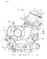
- FIG. 1 is a right side elevational view of an internal combustion engine 1 according to an embodiment of the present invention.
- the internal combustion engine 1 is a water-cooled in-line two-cylinder four-stroke cycle internal combustion engine.
- the rightward direction in FIG. 1 is the forward direction of the vehicle; the upward direction is the upward direction of the vehicle; a depthwise direction (into the page) is the leftward direction of the vehicle; and a direction out of the plane of FIG. 1 (out of the page) is the rightward direction of the vehicle.
- the internal combustion engine 1 of the present embodiment as depicted in FIG. 1 is of the type in which a cylinder and a crankcase are integrated.
- a crankcase 10 rotationally supports a crankshaft 11 which extends in the lateral (left-right) direction of the vehicle.
- the crankcase 10 is formed from upper and lower parts, which can be separated vertically across a crankcase parting plane (hereinafter referred to simply as a "parting plane") 10a, which passes through the centre of the crankshaft 11.
- An upper side half 10A and a lower side half 10B of the crankcase 10 are fastened to each other by bolts along the parting plane 10a.
- a cylinder block 12 is provided at an upper portion of the upper side half 10A.
- the cylinder block 12 is formed as a unitary member and has two cylinder bores arrayed in series.
- a cylinder head 13 is placed on and fastened to the cylinder block 12 such that a cylinder axis X is inclined somewhat forwardly.
- a cylinder head cover 14 is placed on and fastened to the cylinder head 13.
- An oil pan 15 is attached under the lower side half 10B.
- An intake pipe (not shown) is connected to an intake port 16 of and extends rearwardly from a rear portion of the cylinder head 13 of the internal combustion engine 1.
- the intake pipe extends to an intake system including a throttle body, an air cleaner and so forth (not shown).
- An exhaust pipe (not shown) is connected to an exhaust port 17 of and extends forwardly from a front portion of the cylinder head 13.
- the exhaust pipe extends to an exhaust system including a muffler and so forth (not shown).
- crankshaft 11 is supported for rotation on the crankcase 10 and is sandwiched along the parting plane 10a between and by the upper side half 10A and the lower side half 10B.
- a transmission 4 is disposed behind the crankshaft 11 in the crankcase 10 (refer to FIG. 5 ).
- the transmission 4 is a gear transmission of the constant-mesh type, and includes a main shaft 41 and a countershaft 42.
- the main shaft 41 of the transmission 4 is rotatably supported on the upper side half 10A to the rear of and above the crankshaft 11 such that it extends in parallel to the crankshaft 11.
- the countershaft 42 is rotatably supported along the parting plane 10a and sandwiched between the upper side half 10A and the lower side half 10B to the rear of the crankshaft 11 and the main shaft 41 such that it extends in parallel to the crankshaft 11 (refer to FIGS. 2 and 5 ).
- paired gears of transmission gear groups 41g and 42g which are mounted on the main shaft 41 and the countershaft 42 respectively, are held in meshing engagement with each other. Gear changeover is carried out by a speed changing operation mechanism 43 so that the transmission 4 can carry out a speed change.
- a known multi-plate clutch apparatus 5 (not shown in FIG. 5 ) is provided at a right end portion of the main shaft 41 such that the right end portion of the main shaft 41 serves as a centre shaft 5a of the clutch apparatus 5 (refer to FIG. 2 ). Rotation of the crankshaft 11 is transmitted to the main shaft 41 through the clutch apparatus 5.
- Rotational power of the crankshaft 11 is transmitted to the clutch apparatus 5 through a primary driving gear 18 (refer to FIGS. 2 and 5 ) at the crankshaft 11 side and a primary driven gear (not shown) at the clutch apparatus 5 side.
- the clutch apparatus 5 is configured such that, during gear changeover of the transmission 4, it does not transmit the rotational power of the crankshaft 11 to the transmission 4; the rotational power of the crankshaft 11 to the transmission 4 is only transmitted when the gear changeover of the transmission 4 is completed.
- crankcase cover 20R the right side of the crankcase 10 is covered with a right crankcase cover ("case cover" in the present invention) 20R over a large area across the upper side half 10A and the lower side half 10B.
- the crankshaft 11, a balancer shaft 61, an oil pump driving shaft 81, the centre shaft 5a of the clutch apparatus 5 (namely, the main shaft 41), and the countershaft 42 are positioned in that order from the front side and are covered with the right crankcase cover 20R.
- a water pump 21 for cooling water is provided on the right crankcase cover 20R, forward of the crankshaft 11.
- a right projecting wall 19R is formed on a right side wall 10R of the crankcase 10 such that it projects to the right from the upper side half 10A and the lower side half 10B.
- a right end face of the right projecting wall 19R serves as a mating face 10b with the right crankcase cover 20R.
- the right projecting wall 19R has an annular (closed-circuit) shape along an outer edge of the right crankcase cover 20R (refer to FIGS. 1 , 4 , and 5 ).
- the right projecting wall 19R includes an upper side right projecting wall 19RA of the upper side half 10A and a lower side projecting wall 19RB of the lower side half 10B.
- the upper side right projecting wall 19RA and the lower side projecting wall 19RB are fastened together at the end portions 19a thereof, whereby the annular right projecting wall 19R is formed.
- a left projecting wall is also formed on a left side wall 10L (refer to FIG. 7 ) of the crankcase 10 in a similar manner.
- the left projecting wall projects to the left from the upper side half 10A and the lower side half 10B and has a left end face positioned at a mating plane with the left crankcase cover (not shown).
- the left projecting wall has an annular shape along an outer edge of the left crankcase cover.
- crankshaft 11 As shown in FIG. 2 , in which the right crankcase cover 20R is removed, a right end portion of the crankshaft 11 is positioned on the inner side of the annular right projecting wall 19R.
- the crankshaft 11 extends through and is supported for rotation on the right side wall 10R along the parting plane 10a between the upper side half 10A and the lower side half 10B of the crankcase 10.
- the balancer shaft 61 of a balancer 6 and the oil pump driving shaft 81 are positioned on the lower side half 10B.
- the balancer 6 has a balance weight 60 at a location behind and below the crankshaft 11.
- an oil pump 8 and the balancer 6 are disposed on the lower side half 10B of the crankcase 10, to achieve a lower disposition of the centre of gravity of the internal combustion engine 1.
- the main shaft 41 of the transmission 4 is provided in parallel to the crankshaft 11 on the upper side half 10A at a location behind and above the balancer shaft 61 and the oil pump driving shaft 81.
- a right end of the main shaft 41 extends through and is supported for rotation on the right side wall 10R of the upper side half 10A of the crankcase 10.
- the clutch apparatus 5 is provided at an end portion of the main shaft 41 such that the centre shaft 5a thereof is coaxial with the main shaft 41.
- the clutch apparatus 5 is disposed behind the crankshaft 11 such that it is driven to rotate by the crankshaft 11.
- the balancer shaft 61 and the oil pump driving shaft 81 are disposed between the crankshaft 11 and the centre shaft 5a of the clutch apparatus 5 in the longitudinal (front-rear) direction.
- the oil pump 8 and the balancer 6, which are heavy articles, are positioned near to the longitudinal centre, and so the centre of gravity of the internal combustion engine 1 is positioned nearer to the longitudinal centre.
- the countershaft 42 of the transmission 4 is rotatably supported on the right side wall 10R and the left side wall 10L (refer to FIG. 7 ) along the parting plane 10a between the upper side half 10A and the lower side half 10B of the crankcase 10 to the rear of the main shaft 41.
- the countershaft 42 extends rightwardly through the right side wall 10R.
- the primary driving gear 18 is fitted at a right end portion of the crankshaft 11 extending through the right side wall 10R.
- a camshaft driving sprocket wheel 27 is fitted (refer to FIG. 2 ).
- the camshaft driving sprocket wheel 27 meshes with a cam chain 26 of a chain mechanism 25 which drives a valve system (not shown) of the internal combustion engine 1.
- Rotational power of the crankshaft 11 is transmitted to the clutch apparatus 5 through the primary driving gear 18 and the primary driven gear (not shown) attached to the clutch apparatus 5.
- the primary driving gear 18 includes a so-called scissors structure.
- the primary driving gear 18 has a two-part structure including a main gear 18A and a subgear 18B disposed along the axial direction.
- the main gear 18A and the subgear 18B which has a smaller width are placed on each other in the axial direction, and mesh with the primary driven gear (not shown) which is the counterpart gear.
- the main gear 18A is supported fixedly on the crankshaft 11.
- the subgear 18B is fitted for idling rotation on a boss of the main gear 18A (see boss 62a of a main gear 62A of a balancer driven gear 62 in FIG. 6 ).
- the main gear 18A and the subgear 18B have equal diameters and equal pitch, and both mesh with the same gear teeth of the counterpart primary driven gear (not shown).
- a biasing member (not shown) is interposed between the main and subgears 18A and 18B so that the gears 18A and 18B are biased to turn in opposite directions to each other.
- the primary driving gear 18 drives the primary driven gear to rotate
- the main gear 18A and the subgear 18B of the primary driving gear 18 mesh with the primary driven gear, which is the counterpart gear of the meshing engagement, while the meshing teeth of the primary driven gear are biased away from each other through the meshing teeth of the main gear 18A and the subgear 18B by the biasing member. Therefore, backlash between the primary driven gear and the main gear 18A and subgear 18B is substantially eliminated.
- the primary driving gear 18 can mesh with the primary driven gear without a play in the meshing region between them. Therefore, generation of gear noise, vibration and so forth when rotational power is transmitted to the primary driven gear can be reduced or prevented.
- the balancer 6 includes the balancer driven gear 62, which has the balance weight 60 thereon and is supported for rotation on the balancer shaft 61 through a needle bearing 64.
- the balancer driven gear 62 is held in meshing engagement with the main gear 18A of the primary driving gear 18. (It is to be noted that, in FIG. 2 , the primary driving gear 18 is depicted at the subgear 18B side thereof and meshing engagement thereof with the balancer driven gear 62 is not shown clearly.)
- the balance weight 60 is formed on an outer side face of the balancer driven gear 62, facing the right crankcase cover 20R.
- the oil pump driving shaft 81 can be disposed in a neighbouring relationship with the balancer shaft 61.
- a pump driving gear 63 is connected for driven rotation through an Oldham coupling 65.
- the pump driving gear 63 has a smaller diameter than the balancer driven gear 62, and is supported for rotation on the balancer shaft 61.
- the pump driving gear 63 is held in meshing engagement with a pump driven gear 82 of the oil pump driving shaft 81 (refer to FIG. 2 ).
- the balancer 6 is disposed in the case-cover space 22 between the crankcase 10 and the right crankcase cover 20R.
- the right crankcase cover 20R has an inner side face 20Ra which has, on an outer periphery thereof, a cover side mating face 20Rb which coincides with the mating face 10b of the right projecting wall 19 of the crankcase 10.
- the right crankcase cover 20R includes the water pump 21 provided at a front portion thereof and a clutch apparatus cover portion 28 provided at a rear portion thereof.
- the right crankcase cover 20R further includes a crankshaft end cover portion 29 provided at a substantially central location thereof.
- a cover side supporting portion 23 is formed at a lower location longitudinally between the clutch apparatus cover portion 28 and the crankshaft end cover portion 29.
- the cover side supporting portion 23 supports a right end of the balancer shaft 61 (as shown in FIG. 6 ).
- the balancer shaft 61 is supported at a left end thereof on a case side supporting portion 24 (refer to FIG. 3 ) formed on the right side wall 10R of the lower side half 10B of the crankcase 10.
- the balancer shaft 61 does not occupy space in the crankcase 10, and can be disposed next to the oil pump driving shaft 81.
- the balancer driven gear 62 and the pump driving gear 63 of the balancer 6 are disposed such that the balancer driven gear 62 is positioned nearer to the right crankcase cover 20R in the direction of the balancer shaft 61 in the case-cover space 22.
- the pump driving gear 63 which has a smaller diameter, is disposed nearer to the face of the right side wall 10R of the crankcase 10.
- the pump driven gear 82 of the oil pump driving shaft 81 can be positioned near to the pump driving gear 63, and the balancer shaft 61 and the oil pump driving shaft 81 can be disposed next to each other.
- the balancer driven gear 62 of the balancer 6 also includes a so-called scissors structure, similar to the primary driving gear 18.
- the balancer driven gear 62 has a two-part structure including a main gear 62A and a subgear 62B in an axial direction, and the subgear 62B is fitted for idling rotation on a boss 62a of the main gear 62A.
- the main gear 62A and the subgear 62B which has a smaller gear width are coaxially placed one on the other in an axial direction.
- the gears 62A and 62B are biased to turn in opposite directions to each other and held in meshing engagement with the main gear 18A of the primary driving gear 18 which is the counterpart gear of the meshing engagement.
- the primary driving gear 18 can mesh with the balancer driven gear 62 without a play in the meshing region therebetween, generation of gear noise, vibration and so forth when rotational power is transmitted to the balancer driven gear 62 is reduced or prevented.
- FIG. 3 shows a state in which the balancer 6, primary driving gear 18, and clutch apparatus 5 have been removed compared with the state shown in FIG. 2 .
- Reference symbol 24 in FIG. 3 denotes the case side supporting portion for the balancer shaft 61, which is formed on the right side wall 10R of the lower side half 10B of the crankcase 10.
- reference symbol 60A denotes a locus of rotation of an outer periphery 60a (refer to FIG. 2 ) when the balance weight 60 depicted in FIG. 2 rotates.
- the oil pump driving shaft 81 is disposed in parallel to the balancer shaft 61, behind and below the case side supporting portion 24.
- the pump driven gear 82 is attached to the oil pump driving shaft 81 and meshes with the pump driving gear 63 of the balancer 6.
- the balancer 6 and the oil pump 8 are disposed on the lower side half of the crankcase 10.
- the balancer shaft 61 is disposed lower than the crankshaft 11, and the oil pump driving shaft 81 is disposed lower than the balancer shaft 61.
- the balancer shaft 61 and the oil pump driving shaft 81 are disposed between the crankshaft 11 and the centre shaft 5a of the clutch apparatus 5 located behind the crankshaft 11 (refer to FIG. 2 ).
- the oil pump 8 and the balancer 6, which are heavy articles, are disposed at a low location. Consequently, the centre of gravity of the internal combustion engine 1 is lowered and can be placed near to the longitudinal centre.
- the oil pump 8 is accommodated and attached in an oil pump accommodation chamber 30.
- the oil pump accommodation chamber 30 is defined by an oil chamber partition 31 in the inside of a lower portion between the left side wall 10L and the right side wall 10R of the lower side half 10B of the crankcase 10.
- the oil pump accommodation chamber 30 communicates at a lower portion thereof with the inside of the oil pan 15.
- the oil pump driving shaft 81 extends in parallel to the balancer shaft 61 and includes a first shaft portion 81A and a second shaft portion 81 B, which are formed as separate members from each other.
- the first shaft portion 81A extends through the inside of the oil pump 8.
- the second shaft portion 81 B has the pump driven gear 82 which engages with the pump driving gear 63 of the balancer 6.
- a right end portion 81Ab of the first shaft portion 81A and a left end portion 81Ba of the second shaft portion 81 B engage with and are connected to each other.
- a right end portion 81 Bb of the second shaft portion 81 B extends through the right side wall 10R of the lower side half 10B and is supported for rotation on the right side wall 10R (refer to FIG. 6 ).
- a restriction member 83 contacts a right end of the oil pump driving shaft 81, that is, it is in contact with the right end portion 81 Bb of the second shaft portion 81 B.
- the restriction member 83 restricts rightward movement of the oil pump driving shaft 81 in the axial direction.
- the restriction member 83 is fastened to a side wall face 10Ra of the right side wall 10R of the crankcase 10 by a fastening member 84 (refer to FIGS. 3 , 5 , and 6 ).
- restriction member 83 and the fastening member 84 are positioned such that they are included in an area of rotation of the balance weight 60 (within the locus 60A of rotation), as viewed in the axial direction of the oil pump driving shaft 81 as shown in FIG. 3 . Therefore, parts in the internal combustion engine 1 are disposed intensively, and consequently, the internal combustion engine 1 can be made compact.
- the oil pump 8 which is a heavy article is accommodated in the oil pump accommodation chamber 30 provided between the left side wall 10L and the right side wall 10R of the lower side half 10B of the crankcase 10. Therefore, the oil pump 8 can be disposed nearer to the lateral centre of the internal combustion engine 1, and the centre of gravity of the internal combustion engine 1 can be positioned nearer to the lateral centre.
- the oil pump driving shaft 81 is formed from separate parts, the oil pump 8 can be attached readily in the inside of the oil pump accommodation chamber 30 of the crankcase 10.
- the internal combustion engine 1 of the present embodiment includes a crankcase 10, a right crankcase cover 20R which covers a right side of the crankcase 10, a crankshaft 11 and a balancer shaft 61, a balancer 6 having a balancer driven gear 62 and a balance weight 60 provided on the balancer driven gear 62, the balancer 6 being acted upon and driven by driving force of the crankshaft 11 to rotate, and an oil pump 8 accommodated in the crankcase 10 and having an oil pump driving shaft 81 disposed in parallel to the crankshaft 11 and the balancer shaft 61, the oil pump 8 including a pump driven gear 82.
- the balancer 6 includes a pump driving gear 63 which has a diameter smaller than that of the balancer driven gear 62 and rotates together with the balancer driven gear 62, and the pump driving gear 63 meshes with the pump driven gear 82. Furthermore, the oil pump driving shaft 81 is disposed within a range of rotation of the balance weight 60 as viewed in an axial direction thereof.
- the balancer shaft 61 and the oil pump driving shaft 81 can be disposed next to each other to make the internal combustion engine 1 compact.
- the balancer 6 is disposed in a case-cover space 22 between the crankcase 10 and the right crankcase cover 20R. Further, the balancer shaft 61 is supported by a case side supporting portion 24 formed on a side wall face 10Ra of a right side wall 10R of the crankcase 10 and a cover side supporting portion 23 formed on an inner side face 20Ra of the right crankcase cover 20R.
- the balancer shaft 61 does not occupy any space in the crankcase 10, and so space utilization and the disposition relationships to other members can be prevented from being restricted. Further, the balancer shaft 61 and the oil pump driving shaft 81 can be disposed more closely to each other.
- the balancer 6 has the balancer driven gear 62 disposed nearer to the right crankcase cover 20R and the pump driving gear 63 disposed nearer to the crankcase 10. Therefore, the balancer driven gear 62 (which has the larger diameter) is disposed nearer to the right crankcase cover 20R, and the pump driving gear 63 (which has a diameter smaller than that of the balancer driven gear 62) is disposed nearer to the side wall face 10Ra of the right side wall 10R of the crankcase 10. Consequently, the oil pump driving shaft 81 can be disposed more closely to the balancer shaft 61.
- the balance weight 60 is formed on the side face of the balancer driven gear 62 which faces the right crankcase cover 20R. Therefore, the case side space 22A near the crankcase 10 is not occupied by the balance weight 60, and the oil pump driving shaft 81 can be disposed more closely to the balancer shaft 61.
- the internal combustion engine 1 further includes a restriction member 83 fastened and attached to a side wall face 10Ra of the right side wall 10R of the crankcase 10 by a fastening member 84, and which is configured to restrict axial movement of the oil pump driving shaft 81.
- the restriction member 83 and the fastening member 84 are included in the area of rotation of the balance weight 60 as viewed in the axial direction of the oil pump driving shaft 81. Therefore, parts in the internal combustion engine 1 are disposed nearer to each other and the internal combustion engine 1 can be made compact.
- crankcase 10 is configured from upper and lower side halves, and the balancer 6 and the oil pump 8 are disposed on the lower side half 10B of the crankcase 10 to achieve a lower disposition of the centre of gravity while the oil pump driving shaft 81 is disposed below the balancer shaft 61. Therefore, the oil pump 8 (which is heavy) can be disposed at a lower portion of the internal combustion engine 1, and the centre of gravity of the internal combustion engine 1 can be disposed at a low position.
- the internal combustion engine 1 further includes a transmission 4 and a clutch apparatus 5 disposed to the rear of the crankshaft 11 and driven to rotate by the crankshaft 11. Further, the balancer shaft 61 and the oil pump driving shaft 81 are disposed longitudinally between the crankshaft 11 and a centre shaft 5a of the clutch apparatus 5. Therefore, the oil pump 8 and the balancer 6 which are heavy articles can be disposed nearer to the longitudinal centre of the internal combustion engine 1. This contributes to the disposition of the centre of gravity of the internal combustion engine 1 rather nearer to the longitudinal centre of the internal combustion engine 1.
- the oil pump 8 is accommodated in an oil pump accommodation chamber 30 defined in the crankcase 10, and the oil pump driving shaft 81 is configured from a plurality of shaft members including a first shaft portion 81A extending through the inside of the oil pump 8 and a second shaft portion 81 B having the pump driven gear 82 engaging with the pump driving gear 63 of the balancer 6. Further, the first shaft portion 81A and the second shaft portion 81 B engage with and are connected to each other at right end portion 81Ab and left end portion 81Ba thereof. Therefore, since the oil pump driving shaft 81 is formed from separate parts, attachment of the oil pump 8 to the inside of the crankcase 10 is facilitated.
- the oil pump driving shaft 81 can be extended, the oil pump 8 which is a heavy article can be disposed nearer to the lateral centre of the internal combustion engine 1. This contributes to the disposition of the centre of gravity of the internal combustion engine 1 nearer to the lateral centre of the internal combustion engine 1.
- the internal combustion engine of the present invention may be any of various internal combustion engines, not only of the vehicle-carried type but also of the stationary type, as long as the internal combustion engine has the configuration of claim 1.
- the internal combustion engine may be air-cooled or water-cooled, and may have any number of cylinders.
- the oil pump may be any oil pump which has the configuration of claim 1.
- balancer driven gear and the balance weight in the embodiment described above are integrated with each other, it is only necessary for the balancer driven gear and the balance weight to rotate integrally with each other. Therefore, the balancer driven gear and the balance weight may be formed as separate members from each other.
Abstract
Description
- The present invention relates to an internal combustion engine including a balancer, which has a compact structure.
- A known structure is disclosed, for example, in Japanese Patent Laid-Open No.
2009-162202 Figures 2 ,4 , and5 ). The known structure includes a balancer which generates a vibromotive force opposite to the vibromotive force generated by a piston-crank system of the internal combustion engine, to cancel the vibration. - Further, in the internal combustion engine disclosed in Japanese Patent Laid-Open No.
2009-162202 - However, in the case of the internal combustion engine disclosed in Japanese Patent Laid-Open No.
2009-162202 - Based on the above, it is an object of at least the preferred embodiment of the present invention to provide an internal combustion engine including a balancer wherein a balancer shaft and an oil pump driving shaft can be disposed in a neighbouring relationship with each other, space utilization and disposition relationship to other members can be prevented from being restricted, and the internal combustion engine can be made compact.
- According to a first aspect of the present invention, there is provided an internal combustion engine, comprising: a crankcase; a case cover which covers a side of the crankcase; a crankshaft; a balancer shaft; a balancer including a balancer driven gear and a balance weight provided on the balancer driven gear, the balancer being acted upon and driven to rotate by driving force of the crankshaft; and an oil pump accommodated in the crankcase and having an oil pump driving shaft disposed in parallel to the crankshaft and the balancer shaft, the oil pump including a pump driven gear, wherein the balancer has a pump driving gear which has a diameter smaller than that of the balancer driven gear and rotates together with the balancer driven gear, the pump driving gear meshing with the pump driven gear, and the oil pump driving shaft is disposed within an area of rotation of the balance weight as viewed in an axial direction thereof.
- In this arrangement, the balancer includes the balance weight provided on the balancer driven gear, and the pump driving gear which has a smaller diameter smaller than the balancer driven gear and is connected to the balancer driven gear is provided on the balancer shaft. Further, the pump driven gear on the oil pump driving shaft meshes with the pump driving gear, and the oil pump driving shaft is disposed within the range of rotation of the balance weight. Therefore, the balancer shaft and the oil pump driving shaft can be disposed near to each other to make the internal combustion engine compact.
- Preferably, the balancer is disposed in a space between the crankcase and the case cover, and the balancer shaft is supported by a case side supporting portion formed on a side wall face of the crankcase and a cover side supporting portion formed on an inner side face of the case cover.
- With this arrangement, the balancer shaft does not occupy space in the crankcase, and the space utilization and the disposition relationship to other members can be prevented from being restricted. Further, the balancer shaft and the oil pump driving shaft can be disposed more closely to each other.
- Preferably, the balancer has the balancer driven gear disposed nearer to the case cover and the pump driving gear disposed nearer to the crankcase.
- Thus, the oil pump driving shaft can be disposed nearer to the balancer shaft.
- Preferably, the balance weight is formed on the side face of the balancer driven gear which faces the case cover.
- With this arrangement, the space at the side facing the crankcase is not occupied by the balance weight, and the oil pump driving shaft can be disposed more closely to the balancer shaft.
- Preferably, the internal combustion engine further comprises a restriction member fastened and attached to a side wall face of the crankcase by a fastening member and configured to restrict movement of the oil pump driving shaft in an axial direction, the restriction member and the fastening member being located in the area of rotation of the balance weight as viewed in the axial direction of the oil pump driving shaft.
- Since the restriction member and the fastening member are disposed so as to be included in the area of rotation of the balance weight, the parts of the internal combustion engine are disposed intensively (close to each other), and the internal combustion engine can be made compact.
- Preferably, the crankcase is configured from upper and lower side halves, and the balancer and the oil pump are disposed on a lower side half of the crankcase, and the oil pump driving shaft is disposed lower than the balancer shaft.
- With this arrangement, the oil pump and the balancer are disposed on the lower side half of the crankcase to achieve a lower disposition of the centre of gravity. Furthermore, the oil pump driving shaft is disposed below the balancer shaft. Therefore, the oil pump (which is a heavy article) can be disposed at a lower portion of the internal combustion engine, and the centre of gravity of the internal combustion engine can be disposed at a low position.
- Preferably, the internal combustion engine further includes a transmission; and a clutch apparatus disposed to the rear of the crankshaft and driven to rotate by the crankshaft, the balancer shaft and the oil pump driving shaft being disposed longitudinally between the crankshaft and a centre shaft of the clutch apparatus.
- With this arrangement, the oil pump and the balancer, which are heavy articles, can be disposed nearer to the longitudinal centre of the internal combustion engine, which contributes to the disposition of the centre of gravity of the internal combustion engine nearer to the longitudinal centre of the internal combustion engine.
- Preferably, the oil pump is accommodated in an oil pump accommodation chamber defined in the crankcase, and the oil pump driving shaft is configured from a plurality of shaft members including a first shaft portion extending through the inside of the oil pump and a second shaft portion having the pump driven gear engaging with the pump driving gear of the balancer, the first shaft portion and the second shaft portion engaging with and being connected to each other at end portions thereof.
- Since the oil pump driving shaft is formed from separate parts, attachment of the oil pump to the inside of the crankcase is facilitated. Further, since the oil pump driving shaft can be extended, the heavy oil pump can be disposed nearer to the lateral centre of the internal combustion engine. This contributes to the disposition of the centre of gravity of the internal combustion engine nearer to the lateral centre of the internal combustion engine.
- A preferred embodiment of the invention will now be described by way of example only and with reference to the accompanying drawings, in which:
-
FIG. 1 is a right side elevational view of an internal combustion engine according to an embodiment of the present invention; -
FIG. 2 is an enlarged partially cross-sectional right side elevational view depicting a crankshaft, a balancer and members around them, with a right crankcase cover removed from the internal combustion engine depicted inFIG. 1 ; -
FIG. 3 is an enlarged partially cross-sectional right side elevational view depicting a case side supporting portion for the balancer, a pump driven gear and members around them with the balancer, a primary driving gear, and a clutch apparatus removed inFIG. 2 ; -
FIG. 4 is a left side elevational view depicting a left inner face of the right crankcase cover depicted inFIG. 1 ; -
FIG. 5 is a partial perspective view depicting the balancer and members around the same on a lower side half body as viewed in from above, behind and to the right, with an upper side half body and the right crankcase cover as well as a clutch apparatus removed in the internal combustion engine of the present embodiment; -
FIG. 6 is a sectional developed view taken along line VI-VI inFIGS. 2 and3 ; and -
FIG. 7 is a vertical cross-sectional view taken along line VII-VII inFIG. 1 . -
FIG. 1 is a right side elevational view of an internal combustion engine 1 according to an embodiment of the present invention. The internal combustion engine 1 is a water-cooled in-line two-cylinder four-stroke cycle internal combustion engine. - Directions as such forward, rearward, left, right, up, and down as used in the description of the present specification and the claims should be interpreted with reference to a vehicle (not shown in the drawings) such as, for example, a motorcycle, with the internal combustion engine 1 attached to the vehicle (motorcycle) in a posture as depicted in
FIG. 1 - In the posture depicted in
FIG. 1 , the rightward direction inFIG. 1 is the forward direction of the vehicle; the upward direction is the upward direction of the vehicle; a depthwise direction (into the page) is the leftward direction of the vehicle; and a direction out of the plane ofFIG. 1 (out of the page) is the rightward direction of the vehicle. - In the drawings, arrow FR denotes the forward direction, LH the leftward direction, RH the rightward direction, and UP the upward direction with reference to the direction of the vehicle.
- The internal combustion engine 1 of the present embodiment as depicted in
FIG. 1 is of the type in which a cylinder and a crankcase are integrated. Acrankcase 10 rotationally supports acrankshaft 11 which extends in the lateral (left-right) direction of the vehicle. Thecrankcase 10 is formed from upper and lower parts, which can be separated vertically across a crankcase parting plane (hereinafter referred to simply as a "parting plane") 10a, which passes through the centre of thecrankshaft 11. Anupper side half 10A and alower side half 10B of thecrankcase 10 are fastened to each other by bolts along theparting plane 10a. - A
cylinder block 12 is provided at an upper portion of theupper side half 10A. Thecylinder block 12 is formed as a unitary member and has two cylinder bores arrayed in series. Acylinder head 13 is placed on and fastened to thecylinder block 12 such that a cylinder axis X is inclined somewhat forwardly. Acylinder head cover 14 is placed on and fastened to thecylinder head 13. - An
oil pan 15 is attached under thelower side half 10B. - An intake pipe (not shown) is connected to an
intake port 16 of and extends rearwardly from a rear portion of thecylinder head 13 of the internal combustion engine 1. The intake pipe extends to an intake system including a throttle body, an air cleaner and so forth (not shown). - An exhaust pipe (not shown) is connected to an
exhaust port 17 of and extends forwardly from a front portion of thecylinder head 13. The exhaust pipe extends to an exhaust system including a muffler and so forth (not shown). - The
crankshaft 11 is supported for rotation on thecrankcase 10 and is sandwiched along theparting plane 10a between and by theupper side half 10A and thelower side half 10B. Atransmission 4 is disposed behind thecrankshaft 11 in the crankcase 10 (refer toFIG. 5 ). - The
transmission 4 is a gear transmission of the constant-mesh type, and includes amain shaft 41 and acountershaft 42. Themain shaft 41 of thetransmission 4 is rotatably supported on theupper side half 10A to the rear of and above thecrankshaft 11 such that it extends in parallel to thecrankshaft 11. - The
countershaft 42 is rotatably supported along theparting plane 10a and sandwiched between theupper side half 10A and thelower side half 10B to the rear of thecrankshaft 11 and themain shaft 41 such that it extends in parallel to the crankshaft 11 (refer toFIGS. 2 and5 ). - As shown in
FIG. 5 , in thetransmission 4, paired gears oftransmission gear groups main shaft 41 and thecountershaft 42 respectively, are held in meshing engagement with each other. Gear changeover is carried out by a speedchanging operation mechanism 43 so that thetransmission 4 can carry out a speed change. - A known multi-plate clutch apparatus 5 (not shown in
FIG. 5 ) is provided at a right end portion of themain shaft 41 such that the right end portion of themain shaft 41 serves as acentre shaft 5a of the clutch apparatus 5 (refer toFIG. 2 ). Rotation of thecrankshaft 11 is transmitted to themain shaft 41 through theclutch apparatus 5. - Rotational power of the
crankshaft 11 is transmitted to theclutch apparatus 5 through a primary driving gear 18 (refer toFIGS. 2 and5 ) at thecrankshaft 11 side and a primary driven gear (not shown) at theclutch apparatus 5 side. Theclutch apparatus 5 is configured such that, during gear changeover of thetransmission 4, it does not transmit the rotational power of thecrankshaft 11 to thetransmission 4; the rotational power of thecrankshaft 11 to thetransmission 4 is only transmitted when the gear changeover of thetransmission 4 is completed. - As shown in
FIG. 1 , the right side of thecrankcase 10 is covered with a right crankcase cover ("case cover" in the present invention) 20R over a large area across theupper side half 10A and thelower side half 10B. Thecrankshaft 11, abalancer shaft 61, an oilpump driving shaft 81, thecentre shaft 5a of the clutch apparatus 5 (namely, the main shaft 41), and thecountershaft 42 are positioned in that order from the front side and are covered with theright crankcase cover 20R. - It should be noted that a
water pump 21 for cooling water is provided on theright crankcase cover 20R, forward of thecrankshaft 11. - As shown in
FIG. 2 , aright projecting wall 19R is formed on aright side wall 10R of thecrankcase 10 such that it projects to the right from theupper side half 10A and thelower side half 10B. A right end face of theright projecting wall 19R serves as amating face 10b with theright crankcase cover 20R. Theright projecting wall 19R has an annular (closed-circuit) shape along an outer edge of the right crankcase cover 20R (refer toFIGS. 1 ,4 , and5 ). - The
right projecting wall 19R includes an upper side right projecting wall 19RA of theupper side half 10A and a lower side projecting wall 19RB of thelower side half 10B. When theupper side half 10A and thelower side half 10B are fastened together, the upper side right projecting wall 19RA and the lower side projecting wall 19RB are fastened together at theend portions 19a thereof, whereby the annularright projecting wall 19R is formed. - It should be noted that a left projecting wall is also formed on a
left side wall 10L (refer toFIG. 7 ) of thecrankcase 10 in a similar manner. The left projecting wall projects to the left from theupper side half 10A and thelower side half 10B and has a left end face positioned at a mating plane with the left crankcase cover (not shown). The left projecting wall has an annular shape along an outer edge of the left crankcase cover. - As shown in
FIG. 2 , in which theright crankcase cover 20R is removed, a right end portion of thecrankshaft 11 is positioned on the inner side of the annularright projecting wall 19R. Thecrankshaft 11 extends through and is supported for rotation on theright side wall 10R along theparting plane 10a between theupper side half 10A and thelower side half 10B of thecrankcase 10. - The
balancer shaft 61 of abalancer 6 and the oilpump driving shaft 81 are positioned on thelower side half 10B. Thebalancer 6 has abalance weight 60 at a location behind and below thecrankshaft 11. - Accordingly, an
oil pump 8 and thebalancer 6 are disposed on thelower side half 10B of thecrankcase 10, to achieve a lower disposition of the centre of gravity of the internal combustion engine 1. - The
main shaft 41 of thetransmission 4 is provided in parallel to thecrankshaft 11 on theupper side half 10A at a location behind and above thebalancer shaft 61 and the oilpump driving shaft 81. A right end of themain shaft 41 extends through and is supported for rotation on theright side wall 10R of theupper side half 10A of thecrankcase 10. Theclutch apparatus 5 is provided at an end portion of themain shaft 41 such that thecentre shaft 5a thereof is coaxial with themain shaft 41. - In particular, the
clutch apparatus 5 is disposed behind thecrankshaft 11 such that it is driven to rotate by thecrankshaft 11. Thebalancer shaft 61 and the oilpump driving shaft 81 are disposed between thecrankshaft 11 and thecentre shaft 5a of theclutch apparatus 5 in the longitudinal (front-rear) direction. - Accordingly, the
oil pump 8 and thebalancer 6, which are heavy articles, are positioned near to the longitudinal centre, and so the centre of gravity of the internal combustion engine 1 is positioned nearer to the longitudinal centre. - The
countershaft 42 of thetransmission 4 is rotatably supported on theright side wall 10R and theleft side wall 10L (refer toFIG. 7 ) along theparting plane 10a between theupper side half 10A and thelower side half 10B of thecrankcase 10 to the rear of themain shaft 41. Thecountershaft 42 extends rightwardly through theright side wall 10R. - The
primary driving gear 18 is fitted at a right end portion of thecrankshaft 11 extending through theright side wall 10R. At a further tip end side of thecrankshaft 11, a camshaft drivingsprocket wheel 27 is fitted (refer toFIG. 2 ). The camshaft drivingsprocket wheel 27 meshes with acam chain 26 of achain mechanism 25 which drives a valve system (not shown) of the internal combustion engine 1. - Rotational power of the
crankshaft 11 is transmitted to theclutch apparatus 5 through theprimary driving gear 18 and the primary driven gear (not shown) attached to theclutch apparatus 5. Theprimary driving gear 18 includes a so-called scissors structure. - Specifically, as shown in
FIG. 5 , theprimary driving gear 18 has a two-part structure including amain gear 18A and a subgear 18B disposed along the axial direction. Themain gear 18A and the subgear 18B which has a smaller width are placed on each other in the axial direction, and mesh with the primary driven gear (not shown) which is the counterpart gear. - The
main gear 18A is supported fixedly on thecrankshaft 11. Thesubgear 18B is fitted for idling rotation on a boss of themain gear 18A (seeboss 62a of amain gear 62A of a balancer drivengear 62 inFIG. 6 ). - The
main gear 18A and thesubgear 18B have equal diameters and equal pitch, and both mesh with the same gear teeth of the counterpart primary driven gear (not shown). However, a biasing member (not shown) is interposed between the main andsubgears gears - When the
primary driving gear 18 drives the primary driven gear to rotate, themain gear 18A and the subgear 18B of theprimary driving gear 18 mesh with the primary driven gear, which is the counterpart gear of the meshing engagement, while the meshing teeth of the primary driven gear are biased away from each other through the meshing teeth of themain gear 18A and thesubgear 18B by the biasing member. Therefore, backlash between the primary driven gear and themain gear 18A andsubgear 18B is substantially eliminated. - Accordingly, the
primary driving gear 18 can mesh with the primary driven gear without a play in the meshing region between them. Therefore, generation of gear noise, vibration and so forth when rotational power is transmitted to the primary driven gear can be reduced or prevented. - As depicted in
FIG. 6 , thebalancer 6 includes the balancer drivengear 62, which has thebalance weight 60 thereon and is supported for rotation on thebalancer shaft 61 through aneedle bearing 64. The balancer drivengear 62 is held in meshing engagement with themain gear 18A of theprimary driving gear 18. (It is to be noted that, inFIG. 2 , theprimary driving gear 18 is depicted at thesubgear 18B side thereof and meshing engagement thereof with the balancer drivengear 62 is not shown clearly.) - The
balance weight 60 is formed on an outer side face of the balancer drivengear 62, facing theright crankcase cover 20R. Thus, since thebalance weight 60 does not occupy acase side space 22A of a case-cover space 22 facing thecrankcase 10, the oilpump driving shaft 81 can be disposed in a neighbouring relationship with thebalancer shaft 61. - On the opposite side of the balancer driven
gear 62 to the side on which thebalance weight 60 is provided, apump driving gear 63 is connected for driven rotation through anOldham coupling 65. Thepump driving gear 63 has a smaller diameter than the balancer drivengear 62, and is supported for rotation on thebalancer shaft 61. Thepump driving gear 63 is held in meshing engagement with a pump drivengear 82 of the oil pump driving shaft 81 (refer toFIG. 2 ). - The
balancer 6 is disposed in the case-cover space 22 between thecrankcase 10 and theright crankcase cover 20R. - In particular, as depicted in
FIG. 4 , theright crankcase cover 20R has an inner side face 20Ra which has, on an outer periphery thereof, a cover side mating face 20Rb which coincides with themating face 10b of the right projecting wall 19 of thecrankcase 10. Theright crankcase cover 20R includes thewater pump 21 provided at a front portion thereof and a clutchapparatus cover portion 28 provided at a rear portion thereof. Theright crankcase cover 20R further includes a crankshaftend cover portion 29 provided at a substantially central location thereof. A coverside supporting portion 23 is formed at a lower location longitudinally between the clutchapparatus cover portion 28 and the crankshaftend cover portion 29. The coverside supporting portion 23 supports a right end of the balancer shaft 61 (as shown inFIG. 6 ). - The
balancer shaft 61 is supported at a left end thereof on a case side supporting portion 24 (refer toFIG. 3 ) formed on theright side wall 10R of thelower side half 10B of thecrankcase 10. - Accordingly, the
balancer shaft 61 does not occupy space in thecrankcase 10, and can be disposed next to the oilpump driving shaft 81. - The balancer driven
gear 62 and thepump driving gear 63 of thebalancer 6 are disposed such that the balancer drivengear 62 is positioned nearer to theright crankcase cover 20R in the direction of thebalancer shaft 61 in the case-cover space 22. Thepump driving gear 63, which has a smaller diameter, is disposed nearer to the face of theright side wall 10R of thecrankcase 10. - Accordingly, the pump driven
gear 82 of the oilpump driving shaft 81 can be positioned near to thepump driving gear 63, and thebalancer shaft 61 and the oilpump driving shaft 81 can be disposed next to each other. - As shown in
FIGS. 5 and6 , the balancer drivengear 62 of thebalancer 6 also includes a so-called scissors structure, similar to theprimary driving gear 18. In particular, the balancer drivengear 62 has a two-part structure including amain gear 62A and a subgear 62B in an axial direction, and thesubgear 62B is fitted for idling rotation on aboss 62a of themain gear 62A. - The
main gear 62A and the subgear 62B which has a smaller gear width are coaxially placed one on the other in an axial direction. Thegears main gear 18A of theprimary driving gear 18 which is the counterpart gear of the meshing engagement. - Although the scissors structure here is provided on the driven gear side, when the
main gear 18A of theprimary driving gear 18 drives the balancer drivengear 62 of thebalancer 6 to rotate, the backlash is similarly substantially eliminated. - Accordingly, since the
primary driving gear 18 can mesh with the balancer drivengear 62 without a play in the meshing region therebetween, generation of gear noise, vibration and so forth when rotational power is transmitted to the balancer drivengear 62 is reduced or prevented. -
FIG. 3 shows a state in which thebalancer 6,primary driving gear 18, andclutch apparatus 5 have been removed compared with the state shown inFIG. 2 .Reference symbol 24 inFIG. 3 denotes the case side supporting portion for thebalancer shaft 61, which is formed on theright side wall 10R of thelower side half 10B of thecrankcase 10. Further,reference symbol 60A denotes a locus of rotation of anouter periphery 60a (refer toFIG. 2 ) when thebalance weight 60 depicted inFIG. 2 rotates. - The oil
pump driving shaft 81 is disposed in parallel to thebalancer shaft 61, behind and below the caseside supporting portion 24. The pump drivengear 82 is attached to the oilpump driving shaft 81 and meshes with thepump driving gear 63 of thebalancer 6. - In particular, the
balancer 6 and theoil pump 8 are disposed on the lower side half of thecrankcase 10. Thebalancer shaft 61 is disposed lower than thecrankshaft 11, and the oilpump driving shaft 81 is disposed lower than thebalancer shaft 61. Thebalancer shaft 61 and the oilpump driving shaft 81 are disposed between thecrankshaft 11 and thecentre shaft 5a of theclutch apparatus 5 located behind the crankshaft 11 (refer toFIG. 2 ). - Accordingly, the
oil pump 8 and thebalancer 6, which are heavy articles, are disposed at a low location. Consequently, the centre of gravity of the internal combustion engine 1 is lowered and can be placed near to the longitudinal centre. - As shown in
FIG. 7 , theoil pump 8 is accommodated and attached in an oilpump accommodation chamber 30. The oilpump accommodation chamber 30 is defined by anoil chamber partition 31 in the inside of a lower portion between theleft side wall 10L and theright side wall 10R of thelower side half 10B of thecrankcase 10. The oilpump accommodation chamber 30 communicates at a lower portion thereof with the inside of theoil pan 15. - The oil
pump driving shaft 81 extends in parallel to thebalancer shaft 61 and includes afirst shaft portion 81A and asecond shaft portion 81 B, which are formed as separate members from each other. Thefirst shaft portion 81A extends through the inside of theoil pump 8. Thesecond shaft portion 81 B has the pump drivengear 82 which engages with thepump driving gear 63 of thebalancer 6. A right end portion 81Ab of thefirst shaft portion 81A and a left end portion 81Ba of thesecond shaft portion 81 B engage with and are connected to each other. Aright end portion 81 Bb of thesecond shaft portion 81 B extends through theright side wall 10R of thelower side half 10B and is supported for rotation on theright side wall 10R (refer toFIG. 6 ). - A
restriction member 83 contacts a right end of the oilpump driving shaft 81, that is, it is in contact with theright end portion 81 Bb of thesecond shaft portion 81 B. Therestriction member 83 restricts rightward movement of the oilpump driving shaft 81 in the axial direction. Therestriction member 83 is fastened to a side wall face 10Ra of theright side wall 10R of thecrankcase 10 by a fastening member 84 (refer toFIGS. 3 ,5 , and6 ). - Accordingly, rightward movement of the
second shaft portion 81 B of the oilpump driving shaft 81 in the axial direction is restricted by therestriction member 83. Meanwhile, leftward movement of thesecond shaft portion 81 B of the oilpump driving shaft 81 in the axial direction is restricted by engagement of thesecond shaft portion 81 B with thefirst shaft portion 81A, whose movement in the axial direction is restricted in the main body of theoil pump 8. - It is to be noted that the
restriction member 83 and thefastening member 84 are positioned such that they are included in an area of rotation of the balance weight 60 (within thelocus 60A of rotation), as viewed in the axial direction of the oilpump driving shaft 81 as shown inFIG. 3 . Therefore, parts in the internal combustion engine 1 are disposed intensively, and consequently, the internal combustion engine 1 can be made compact. - As described above, the
oil pump 8 which is a heavy article is accommodated in the oilpump accommodation chamber 30 provided between theleft side wall 10L and theright side wall 10R of thelower side half 10B of thecrankcase 10. Therefore, theoil pump 8 can be disposed nearer to the lateral centre of the internal combustion engine 1, and the centre of gravity of the internal combustion engine 1 can be positioned nearer to the lateral centre. - Further, since the oil
pump driving shaft 81 is formed from separate parts, theoil pump 8 can be attached readily in the inside of the oilpump accommodation chamber 30 of thecrankcase 10. - Characteristics of the internal combustion engine of the present embodiment are summarized in the following.
- In particular, the internal combustion engine 1 of the present embodiment includes a
crankcase 10, aright crankcase cover 20R which covers a right side of thecrankcase 10, acrankshaft 11 and abalancer shaft 61, abalancer 6 having a balancer drivengear 62 and abalance weight 60 provided on the balancer drivengear 62, thebalancer 6 being acted upon and driven by driving force of thecrankshaft 11 to rotate, and anoil pump 8 accommodated in thecrankcase 10 and having an oilpump driving shaft 81 disposed in parallel to thecrankshaft 11 and thebalancer shaft 61, theoil pump 8 including a pump drivengear 82. - Further, the
balancer 6 includes apump driving gear 63 which has a diameter smaller than that of the balancer drivengear 62 and rotates together with the balancer drivengear 62, and thepump driving gear 63 meshes with the pump drivengear 82. Furthermore, the oilpump driving shaft 81 is disposed within a range of rotation of thebalance weight 60 as viewed in an axial direction thereof. - Therefore, the
balancer shaft 61 and the oilpump driving shaft 81 can be disposed next to each other to make the internal combustion engine 1 compact. - Further, the
balancer 6 is disposed in a case-cover space 22 between thecrankcase 10 and theright crankcase cover 20R. Further, thebalancer shaft 61 is supported by a caseside supporting portion 24 formed on a side wall face 10Ra of aright side wall 10R of thecrankcase 10 and a coverside supporting portion 23 formed on an inner side face 20Ra of theright crankcase cover 20R. - Therefore, the
balancer shaft 61 does not occupy any space in thecrankcase 10, and so space utilization and the disposition relationships to other members can be prevented from being restricted. Further, thebalancer shaft 61 and the oilpump driving shaft 81 can be disposed more closely to each other. - Further, the
balancer 6 has the balancer drivengear 62 disposed nearer to theright crankcase cover 20R and thepump driving gear 63 disposed nearer to thecrankcase 10. Therefore, the balancer driven gear 62 (which has the larger diameter) is disposed nearer to theright crankcase cover 20R, and the pump driving gear 63 (which has a diameter smaller than that of the balancer driven gear 62) is disposed nearer to the side wall face 10Ra of theright side wall 10R of thecrankcase 10. Consequently, the oilpump driving shaft 81 can be disposed more closely to thebalancer shaft 61. - Further, the
balance weight 60 is formed on the side face of the balancer drivengear 62 which faces theright crankcase cover 20R. Therefore, thecase side space 22A near thecrankcase 10 is not occupied by thebalance weight 60, and the oilpump driving shaft 81 can be disposed more closely to thebalancer shaft 61. - Further, the internal combustion engine 1 further includes a
restriction member 83 fastened and attached to a side wall face 10Ra of theright side wall 10R of thecrankcase 10 by afastening member 84, and which is configured to restrict axial movement of the oilpump driving shaft 81. Further, therestriction member 83 and thefastening member 84 are included in the area of rotation of thebalance weight 60 as viewed in the axial direction of the oilpump driving shaft 81. Therefore, parts in the internal combustion engine 1 are disposed nearer to each other and the internal combustion engine 1 can be made compact. - Further, the
crankcase 10 is configured from upper and lower side halves, and thebalancer 6 and theoil pump 8 are disposed on thelower side half 10B of thecrankcase 10 to achieve a lower disposition of the centre of gravity while the oilpump driving shaft 81 is disposed below thebalancer shaft 61. Therefore, the oil pump 8 (which is heavy) can be disposed at a lower portion of the internal combustion engine 1, and the centre of gravity of the internal combustion engine 1 can be disposed at a low position. - The internal combustion engine 1 further includes a
transmission 4 and aclutch apparatus 5 disposed to the rear of thecrankshaft 11 and driven to rotate by thecrankshaft 11. Further, thebalancer shaft 61 and the oilpump driving shaft 81 are disposed longitudinally between thecrankshaft 11 and acentre shaft 5a of theclutch apparatus 5. Therefore, theoil pump 8 and thebalancer 6 which are heavy articles can be disposed nearer to the longitudinal centre of the internal combustion engine 1. This contributes to the disposition of the centre of gravity of the internal combustion engine 1 rather nearer to the longitudinal centre of the internal combustion engine 1. - Further, the
oil pump 8 is accommodated in an oilpump accommodation chamber 30 defined in thecrankcase 10, and the oilpump driving shaft 81 is configured from a plurality of shaft members including afirst shaft portion 81A extending through the inside of theoil pump 8 and asecond shaft portion 81 B having the pump drivengear 82 engaging with thepump driving gear 63 of thebalancer 6. Further, thefirst shaft portion 81A and thesecond shaft portion 81 B engage with and are connected to each other at right end portion 81Ab and left end portion 81Ba thereof. Therefore, since the oilpump driving shaft 81 is formed from separate parts, attachment of theoil pump 8 to the inside of thecrankcase 10 is facilitated. Further, since the oilpump driving shaft 81 can be extended, theoil pump 8 which is a heavy article can be disposed nearer to the lateral centre of the internal combustion engine 1. This contributes to the disposition of the centre of gravity of the internal combustion engine 1 nearer to the lateral centre of the internal combustion engine 1. - While a preferred embodiment of the internal combustion engine has been described above, the present invention is not limited to the embodiment described above, and the present invention can be carried out in various modes without departing from the scope of the present invention.
- For example, the internal combustion engine of the present invention may be any of various internal combustion engines, not only of the vehicle-carried type but also of the stationary type, as long as the internal combustion engine has the configuration of claim 1. In particular, the internal combustion engine may be air-cooled or water-cooled, and may have any number of cylinders. Also the oil pump may be any oil pump which has the configuration of claim 1.
- Further, while the balancer driven gear and the balance weight in the embodiment described above are integrated with each other, it is only necessary for the balancer driven gear and the balance weight to rotate integrally with each other. Therefore, the balancer driven gear and the balance weight may be formed as separate members from each other.
- Further, although the disposition of the components in the leftward and rightward direction is specified as described in the foregoing description and depicted in the accompanying drawings, the disposition may be reversed in the leftward and rightward direction from that in the embodiment described hereinabove. Also the reverse disposition is included in the present invention.
Claims (8)
- An internal combustion engine (1), comprising:a crankcase (10);a case cover (20R) which covers a side of the crankcase (10);a crankshaft (11);a balancer shaft (61);a balancer (6) including a balancer driven gear (62) and a balance weight (60) provided on the balancer driven gear (62), the balancer (6) being acted upon and driven to rotate by driving force of the crankshaft (11); andan oil pump (8) accommodated in the crankcase (10) and having an oil pump driving shaft (81) disposed in parallel to the crankshaft (11) and the balancer shaft (61), the oil pump (8) including a pump driven gear (82),wherein the balancer (6) has a pump driving gear (63) which has a diameter smaller than that of the balancer driven gear (62) and rotates together with the balancer driven gear (62), the pump driving gear (63) meshing with the pump driven gear (82), andthe oil pump driving shaft (81) is disposed within an area of rotation of the balance weight (60) as viewed in an axial direction thereof.
- The internal combustion engine according to claim 1,
wherein the balancer (6) is disposed in a space (22) between the crankcase (10) and the case cover (20R), and
the balancer shaft (61) is supported by a case side supporting portion (24) formed on a side wall face (10Ra) of the crankcase (10) and a cover side supporting portion (23) formed on an inner side face (20Ra) of the case cover (20R). - The internal combustion engine according to claim 1 or 2, wherein the balancer (6) has the balancer driven gear (62) disposed nearer to the case cover (20R) and the pump driving gear (63) disposed nearer to the crankcase (10).
- The internal combustion engine according to any one of claims 1 to 3, wherein the balance weight (60) is formed on the side face of the balancer driven gear (62) which faces the case cover (20R).
- The internal combustion engine according to any one of claims 1 to 4, further comprising
a restriction member (83) fastened and attached to a side wall face (10Ra) of the crankcase (10) by a fastening member (84) and configured to restrict movement of the oil pump driving shaft (81) in an axial direction, the restriction member (83) and the fastening member (84) being located in the area of rotation of the balance weight (60) as viewed in the axial direction of the oil pump driving shaft (81). - The internal combustion engine according to any one of claims 1 to 5, wherein the crankcase (10) is configured from upper and lower side halves, and the balancer (6) and the oil pump (8) are disposed on a lower side half (10B) of the crankcase (10), and the oil pump driving shaft (81) is disposed lower than the balancer shaft (61).
- The internal combustion engine according to any one of claims 1 to 6, further comprising:a transmission (4); anda clutch apparatus (5) disposed to the rear of the crankshaft (11) and driven to rotate by the crankshaft (11),the balancer shaft (61) and the oil pump driving shaft (81) being disposed longitudinally between the crankshaft (11) and a centre shaft (5a) of the clutch apparatus (5).
- The internal combustion engine according to any one of claims 1 to 7,
wherein the oil pump (8) is accommodated in an oil pump accommodation chamber (30) defined in the crankcase (10), and
the oil pump driving shaft (81) is configured from a plurality of shaft members including a first shaft portion (81A) extending through the inside of the oil pump (8) and a second shaft portion (81 B) having the pump driven gear (82) engaging with the pump driving gear (63) of the balancer (6), the first shaft portion (81A) and the second shaft portion (81 B) engaging with and being connected to each other at end portions (81Ab and 81 Ba) thereof.
Applications Claiming Priority (1)
| Application Number | Priority Date | Filing Date | Title |
|---|---|---|---|
| JP2013199150A JP6078445B2 (en) | 2013-09-26 | 2013-09-26 | Internal combustion engine |
Publications (2)
| Publication Number | Publication Date |
|---|---|
| EP2853702A1 true EP2853702A1 (en) | 2015-04-01 |
| EP2853702B1 EP2853702B1 (en) | 2017-02-22 |
Family
ID=50972572
Family Applications (1)
| Application Number | Title | Priority Date | Filing Date |
|---|---|---|---|
| EP14173144.8A Not-in-force EP2853702B1 (en) | 2013-09-26 | 2014-06-19 | Internal combustion engine |
Country Status (5)
| Country | Link |
|---|---|
| US (1) | US9528569B2 (en) |
| EP (1) | EP2853702B1 (en) |
| JP (1) | JP6078445B2 (en) |
| BR (1) | BR102014023598B1 (en) |
| CA (1) | CA2855331C (en) |
Families Citing this family (9)
| Publication number | Priority date | Publication date | Assignee | Title |
|---|---|---|---|---|
| JP6347150B2 (en) * | 2014-05-14 | 2018-06-27 | スズキ株式会社 | Motorcycle engine cooling system |
| JP6443623B2 (en) * | 2015-02-17 | 2018-12-26 | 日立オートモティブシステムズ株式会社 | Balancer device for internal combustion engine |
| US10119594B2 (en) * | 2015-10-27 | 2018-11-06 | Suzuki Motor Corporation | Balancer device of engine and motorcycle |
| US10119464B2 (en) * | 2016-03-11 | 2018-11-06 | Toyota Motor Engineering & Manufacturing North America, Inc. | Engine assembly having a cover |
| DE102017003390A1 (en) * | 2016-04-26 | 2017-10-26 | Ford Global Technologies, Llc | Gear driven diesel fuel injection pump of an engine |
| US10422253B2 (en) * | 2016-04-26 | 2019-09-24 | Ford Global Technologies, Llc | Cam drive system for an engine |
| KR101905557B1 (en) * | 2016-04-29 | 2018-10-08 | 현대자동차 주식회사 | Balance shaft module |
| US10247275B2 (en) * | 2017-03-13 | 2019-04-02 | GM Global Technology Operations LLC | Crankshaft-balancing assembly and a powertrain |
| US11015675B2 (en) | 2019-01-21 | 2021-05-25 | Harley-Davidson Motor Company Group, LLC | Engine balancer |
Citations (5)
| Publication number | Priority date | Publication date | Assignee | Title |
|---|---|---|---|---|
| US20030037752A1 (en) * | 2001-08-22 | 2003-02-27 | Akifumi Nomura | Engine balancer |
| US20040250789A1 (en) * | 2003-06-13 | 2004-12-16 | Suzuki Motor Corporation | Lubricating structure for engines, lubricating structure for engines for snow vehicles, and snow vehicle |
| DE102006029554A1 (en) * | 2006-06-26 | 2007-12-27 | Pierburg Gmbh | Forces and/or torques compensating device for e.g. piston engine, has displacer unit for supplying oil to internal combustion engine, where displacer unit, compensating shafts and transmission gears are arranged in common housing |
| US20090133661A1 (en) * | 2007-11-28 | 2009-05-28 | Magna Powertrain Ag & Co Kg | Balance shaft unit |
| JP2009162202A (en) | 2008-01-10 | 2009-07-23 | Yamaha Motor Co Ltd | Internal combustion engine and vehicle provided with same |
Family Cites Families (8)
| Publication number | Priority date | Publication date | Assignee | Title |
|---|---|---|---|---|
| JPS6069251A (en) * | 1983-09-26 | 1985-04-19 | Yamaha Motor Co Ltd | Crankcase for multi-cylinder engine |
| JP3757944B2 (en) * | 2003-02-14 | 2006-03-22 | マツダ株式会社 | Engine starter |
| US20090127800A1 (en) * | 2007-11-16 | 2009-05-21 | Kennith Lloyd Tunnell | Crankcase seal for air-cooled engines |
| JP5172421B2 (en) * | 2008-03-28 | 2013-03-27 | 本田技研工業株式会社 | Engine balancer equipment |
| JP2010065630A (en) * | 2008-09-11 | 2010-03-25 | Suzuki Motor Corp | Oil passage structure of engine |
| JP5177221B2 (en) * | 2008-10-20 | 2013-04-03 | トヨタ自動車株式会社 | Motor control device for internal combustion engine system and motor control device |
| JP5352257B2 (en) * | 2009-01-29 | 2013-11-27 | 本田技研工業株式会社 | Internal combustion engine |
| JP2011163252A (en) * | 2010-02-12 | 2011-08-25 | Honda Motor Co Ltd | Engine |
-
2013
- 2013-09-26 JP JP2013199150A patent/JP6078445B2/en active Active
-
2014
- 2014-06-19 EP EP14173144.8A patent/EP2853702B1/en not_active Not-in-force
- 2014-06-27 CA CA2855331A patent/CA2855331C/en not_active Expired - Fee Related
- 2014-09-23 BR BR102014023598-1A patent/BR102014023598B1/en active IP Right Grant
- 2014-09-25 US US14/496,785 patent/US9528569B2/en active Active
Patent Citations (5)
| Publication number | Priority date | Publication date | Assignee | Title |
|---|---|---|---|---|
| US20030037752A1 (en) * | 2001-08-22 | 2003-02-27 | Akifumi Nomura | Engine balancer |
| US20040250789A1 (en) * | 2003-06-13 | 2004-12-16 | Suzuki Motor Corporation | Lubricating structure for engines, lubricating structure for engines for snow vehicles, and snow vehicle |
| DE102006029554A1 (en) * | 2006-06-26 | 2007-12-27 | Pierburg Gmbh | Forces and/or torques compensating device for e.g. piston engine, has displacer unit for supplying oil to internal combustion engine, where displacer unit, compensating shafts and transmission gears are arranged in common housing |
| US20090133661A1 (en) * | 2007-11-28 | 2009-05-28 | Magna Powertrain Ag & Co Kg | Balance shaft unit |
| JP2009162202A (en) | 2008-01-10 | 2009-07-23 | Yamaha Motor Co Ltd | Internal combustion engine and vehicle provided with same |
Also Published As
| Publication number | Publication date |
|---|---|
| CA2855331C (en) | 2016-09-13 |
| CA2855331A1 (en) | 2015-03-26 |
| JP2015063972A (en) | 2015-04-09 |
| BR102014023598A2 (en) | 2015-10-06 |
| JP6078445B2 (en) | 2017-02-08 |
| BR102014023598B1 (en) | 2022-06-14 |
| US9528569B2 (en) | 2016-12-27 |
| EP2853702B1 (en) | 2017-02-22 |
| US20150083068A1 (en) | 2015-03-26 |
Similar Documents
| Publication | Publication Date | Title |
|---|---|---|
| EP2853702B1 (en) | Internal combustion engine | |
| JP4384457B2 (en) | engine | |
| US7325531B2 (en) | Intake structure for V-type internal combustion engine | |
| JP2002266653A (en) | Snow vehicle | |
| JP6208551B2 (en) | Power transmission device | |
| US8316815B2 (en) | Oil storage structure for engine, engine incorporating same, and vehicle incorporating same | |
| JP2011073620A (en) | Hybrid type vehicle | |
| JP5890761B2 (en) | Oil filter arrangement structure of an internal combustion engine for a motorcycle | |
| US9988978B2 (en) | Four-cycle multi-cylinder engine | |
| EP1512854B1 (en) | In-line multicylinder combustion engine | |
| JP6601148B2 (en) | Engine lubrication structure and motorcycle | |
| US10302004B2 (en) | Water pump unit | |
| JP6219658B2 (en) | Saddle riding vehicle | |
| JP6248534B2 (en) | Motorcycle with turbocharger | |
| JP5351587B2 (en) | Internal combustion engine for small vehicles | |
| JP6601135B2 (en) | Four-cycle engine crankcase structure | |
| JP5847152B2 (en) | Internal combustion engine | |
| JP2020159342A (en) | Oil pump drive structure for internal combustion engine | |
| JP2018145902A (en) | Multi-cylinder engine unit | |
| JP2005042558A (en) | Engine unit of saddle type vehicle | |
| JP2014066229A (en) | Internal combustion engine for vehicle |
Legal Events
| Date | Code | Title | Description |
|---|---|---|---|
| PUAI | Public reference made under article 153(3) epc to a published international application that has entered the european phase |
Free format text: ORIGINAL CODE: 0009012 |
|
| 17P | Request for examination filed |
Effective date: 20140619 |
|
| AK | Designated contracting states |
Kind code of ref document: A1 Designated state(s): AL AT BE BG CH CY CZ DE DK EE ES FI FR GB GR HR HU IE IS IT LI LT LU LV MC MK MT NL NO PL PT RO RS SE SI SK SM TR |
|
| AX | Request for extension of the european patent |
Extension state: BA ME |
|
| GRAP | Despatch of communication of intention to grant a patent |
Free format text: ORIGINAL CODE: EPIDOSNIGR1 |
|
| INTG | Intention to grant announced |
Effective date: 20160824 |
|
| GRAS | Grant fee paid |
Free format text: ORIGINAL CODE: EPIDOSNIGR3 |
|
| GRAA | (expected) grant |
Free format text: ORIGINAL CODE: 0009210 |
|
| AK | Designated contracting states |
Kind code of ref document: B1 Designated state(s): AL AT BE BG CH CY CZ DE DK EE ES FI FR GB GR HR HU IE IS IT LI LT LU LV MC MK MT NL NO PL PT RO RS SE SI SK SM TR |
|
| REG | Reference to a national code |
Ref country code: GB Ref legal event code: FG4D |
|
| REG | Reference to a national code |
Ref country code: CH Ref legal event code: EP |
|
| REG | Reference to a national code |
Ref country code: AT Ref legal event code: REF Ref document number: 869453 Country of ref document: AT Kind code of ref document: T Effective date: 20170315 |
|
| REG | Reference to a national code |
Ref country code: IE Ref legal event code: FG4D |
|
| REG | Reference to a national code |
Ref country code: DE Ref legal event code: R096 Ref document number: 602014006862 Country of ref document: DE |
|
| REG | Reference to a national code |
Ref country code: LT Ref legal event code: MG4D |
|
| REG | Reference to a national code |
Ref country code: NL Ref legal event code: MP Effective date: 20170222 |
|
| REG | Reference to a national code |
Ref country code: AT Ref legal event code: MK05 Ref document number: 869453 Country of ref document: AT Kind code of ref document: T Effective date: 20170222 |
|
| PG25 | Lapsed in a contracting state [announced via postgrant information from national office to epo] |
Ref country code: HR Free format text: LAPSE BECAUSE OF FAILURE TO SUBMIT A TRANSLATION OF THE DESCRIPTION OR TO PAY THE FEE WITHIN THE PRESCRIBED TIME-LIMIT Effective date: 20170222 Ref country code: NO Free format text: LAPSE BECAUSE OF FAILURE TO SUBMIT A TRANSLATION OF THE DESCRIPTION OR TO PAY THE FEE WITHIN THE PRESCRIBED TIME-LIMIT Effective date: 20170522 Ref country code: LT Free format text: LAPSE BECAUSE OF FAILURE TO SUBMIT A TRANSLATION OF THE DESCRIPTION OR TO PAY THE FEE WITHIN THE PRESCRIBED TIME-LIMIT Effective date: 20170222 Ref country code: FI Free format text: LAPSE BECAUSE OF FAILURE TO SUBMIT A TRANSLATION OF THE DESCRIPTION OR TO PAY THE FEE WITHIN THE PRESCRIBED TIME-LIMIT Effective date: 20170222 Ref country code: GR Free format text: LAPSE BECAUSE OF FAILURE TO SUBMIT A TRANSLATION OF THE DESCRIPTION OR TO PAY THE FEE WITHIN THE PRESCRIBED TIME-LIMIT Effective date: 20170523 |
|
| PG25 | Lapsed in a contracting state [announced via postgrant information from national office to epo] |
Ref country code: AT Free format text: LAPSE BECAUSE OF FAILURE TO SUBMIT A TRANSLATION OF THE DESCRIPTION OR TO PAY THE FEE WITHIN THE PRESCRIBED TIME-LIMIT Effective date: 20170222 Ref country code: RS Free format text: LAPSE BECAUSE OF FAILURE TO SUBMIT A TRANSLATION OF THE DESCRIPTION OR TO PAY THE FEE WITHIN THE PRESCRIBED TIME-LIMIT Effective date: 20170222 Ref country code: SE Free format text: LAPSE BECAUSE OF FAILURE TO SUBMIT A TRANSLATION OF THE DESCRIPTION OR TO PAY THE FEE WITHIN THE PRESCRIBED TIME-LIMIT Effective date: 20170222 Ref country code: BG Free format text: LAPSE BECAUSE OF FAILURE TO SUBMIT A TRANSLATION OF THE DESCRIPTION OR TO PAY THE FEE WITHIN THE PRESCRIBED TIME-LIMIT Effective date: 20170522 Ref country code: LV Free format text: LAPSE BECAUSE OF FAILURE TO SUBMIT A TRANSLATION OF THE DESCRIPTION OR TO PAY THE FEE WITHIN THE PRESCRIBED TIME-LIMIT Effective date: 20170222 Ref country code: NL Free format text: LAPSE BECAUSE OF FAILURE TO SUBMIT A TRANSLATION OF THE DESCRIPTION OR TO PAY THE FEE WITHIN THE PRESCRIBED TIME-LIMIT Effective date: 20170222 Ref country code: ES Free format text: LAPSE BECAUSE OF FAILURE TO SUBMIT A TRANSLATION OF THE DESCRIPTION OR TO PAY THE FEE WITHIN THE PRESCRIBED TIME-LIMIT Effective date: 20170222 Ref country code: PT Free format text: LAPSE BECAUSE OF FAILURE TO SUBMIT A TRANSLATION OF THE DESCRIPTION OR TO PAY THE FEE WITHIN THE PRESCRIBED TIME-LIMIT Effective date: 20170622 |
|
| PG25 | Lapsed in a contracting state [announced via postgrant information from national office to epo] |
Ref country code: RO Free format text: LAPSE BECAUSE OF FAILURE TO SUBMIT A TRANSLATION OF THE DESCRIPTION OR TO PAY THE FEE WITHIN THE PRESCRIBED TIME-LIMIT Effective date: 20170222 Ref country code: CZ Free format text: LAPSE BECAUSE OF FAILURE TO SUBMIT A TRANSLATION OF THE DESCRIPTION OR TO PAY THE FEE WITHIN THE PRESCRIBED TIME-LIMIT Effective date: 20170222 Ref country code: SK Free format text: LAPSE BECAUSE OF FAILURE TO SUBMIT A TRANSLATION OF THE DESCRIPTION OR TO PAY THE FEE WITHIN THE PRESCRIBED TIME-LIMIT Effective date: 20170222 Ref country code: EE Free format text: LAPSE BECAUSE OF FAILURE TO SUBMIT A TRANSLATION OF THE DESCRIPTION OR TO PAY THE FEE WITHIN THE PRESCRIBED TIME-LIMIT Effective date: 20170222 |
|
| REG | Reference to a national code |
Ref country code: DE Ref legal event code: R097 Ref document number: 602014006862 Country of ref document: DE |
|
| PG25 | Lapsed in a contracting state [announced via postgrant information from national office to epo] |
Ref country code: DK Free format text: LAPSE BECAUSE OF FAILURE TO SUBMIT A TRANSLATION OF THE DESCRIPTION OR TO PAY THE FEE WITHIN THE PRESCRIBED TIME-LIMIT Effective date: 20170222 Ref country code: SM Free format text: LAPSE BECAUSE OF FAILURE TO SUBMIT A TRANSLATION OF THE DESCRIPTION OR TO PAY THE FEE WITHIN THE PRESCRIBED TIME-LIMIT Effective date: 20170222 Ref country code: PL Free format text: LAPSE BECAUSE OF FAILURE TO SUBMIT A TRANSLATION OF THE DESCRIPTION OR TO PAY THE FEE WITHIN THE PRESCRIBED TIME-LIMIT Effective date: 20170222 |
|
| PLBE | No opposition filed within time limit |
Free format text: ORIGINAL CODE: 0009261 |
|
| STAA | Information on the status of an ep patent application or granted ep patent |
Free format text: STATUS: NO OPPOSITION FILED WITHIN TIME LIMIT |
|
| 26N | No opposition filed |
Effective date: 20171123 |
|
| PG25 | Lapsed in a contracting state [announced via postgrant information from national office to epo] |
Ref country code: MC Free format text: LAPSE BECAUSE OF FAILURE TO SUBMIT A TRANSLATION OF THE DESCRIPTION OR TO PAY THE FEE WITHIN THE PRESCRIBED TIME-LIMIT Effective date: 20170222 |
|
| REG | Reference to a national code |
Ref country code: CH Ref legal event code: PL |
|
| PG25 | Lapsed in a contracting state [announced via postgrant information from national office to epo] |
Ref country code: SI Free format text: LAPSE BECAUSE OF FAILURE TO SUBMIT A TRANSLATION OF THE DESCRIPTION OR TO PAY THE FEE WITHIN THE PRESCRIBED TIME-LIMIT Effective date: 20170222 |
|
| REG | Reference to a national code |
Ref country code: IE Ref legal event code: MM4A |
|
| REG | Reference to a national code |
Ref country code: FR Ref legal event code: ST Effective date: 20180228 |
|
| PG25 | Lapsed in a contracting state [announced via postgrant information from national office to epo] |
Ref country code: IE Free format text: LAPSE BECAUSE OF NON-PAYMENT OF DUE FEES Effective date: 20170619 Ref country code: CH Free format text: LAPSE BECAUSE OF NON-PAYMENT OF DUE FEES Effective date: 20170630 Ref country code: LU Free format text: LAPSE BECAUSE OF NON-PAYMENT OF DUE FEES Effective date: 20170619 Ref country code: LI Free format text: LAPSE BECAUSE OF NON-PAYMENT OF DUE FEES Effective date: 20170630 |
|
| PG25 | Lapsed in a contracting state [announced via postgrant information from national office to epo] |
Ref country code: FR Free format text: LAPSE BECAUSE OF NON-PAYMENT OF DUE FEES Effective date: 20170630 |
|
| REG | Reference to a national code |
Ref country code: BE Ref legal event code: MM Effective date: 20170630 |
|
| PG25 | Lapsed in a contracting state [announced via postgrant information from national office to epo] |
Ref country code: BE Free format text: LAPSE BECAUSE OF NON-PAYMENT OF DUE FEES Effective date: 20170630 |
|
| PG25 | Lapsed in a contracting state [announced via postgrant information from national office to epo] |
Ref country code: MT Free format text: LAPSE BECAUSE OF NON-PAYMENT OF DUE FEES Effective date: 20170619 |
|
| PG25 | Lapsed in a contracting state [announced via postgrant information from national office to epo] |
Ref country code: HU Free format text: LAPSE BECAUSE OF FAILURE TO SUBMIT A TRANSLATION OF THE DESCRIPTION OR TO PAY THE FEE WITHIN THE PRESCRIBED TIME-LIMIT; INVALID AB INITIO Effective date: 20140619 |
|
| PGFP | Annual fee paid to national office [announced via postgrant information from national office to epo] |
Ref country code: SK Payment date: 20190528 Year of fee payment: 7 |
|
| PG25 | Lapsed in a contracting state [announced via postgrant information from national office to epo] |
Ref country code: CY Free format text: LAPSE BECAUSE OF FAILURE TO SUBMIT A TRANSLATION OF THE DESCRIPTION OR TO PAY THE FEE WITHIN THE PRESCRIBED TIME-LIMIT Effective date: 20170222 |
|
| PGFP | Annual fee paid to national office [announced via postgrant information from national office to epo] |
Ref country code: GB Payment date: 20190619 Year of fee payment: 6 |
|
| PG25 | Lapsed in a contracting state [announced via postgrant information from national office to epo] |
Ref country code: MK Free format text: LAPSE BECAUSE OF FAILURE TO SUBMIT A TRANSLATION OF THE DESCRIPTION OR TO PAY THE FEE WITHIN THE PRESCRIBED TIME-LIMIT Effective date: 20170222 |
|
| REG | Reference to a national code |
Ref country code: DE Ref legal event code: R084 Ref document number: 602014006862 Country of ref document: DE |
|
| REG | Reference to a national code |
Ref country code: GB Ref legal event code: 746 Effective date: 20191219 |
|
| PG25 | Lapsed in a contracting state [announced via postgrant information from national office to epo] |
Ref country code: TR Free format text: LAPSE BECAUSE OF FAILURE TO SUBMIT A TRANSLATION OF THE DESCRIPTION OR TO PAY THE FEE WITHIN THE PRESCRIBED TIME-LIMIT Effective date: 20170222 |
|
| PG25 | Lapsed in a contracting state [announced via postgrant information from national office to epo] |
Ref country code: AL Free format text: LAPSE BECAUSE OF FAILURE TO SUBMIT A TRANSLATION OF THE DESCRIPTION OR TO PAY THE FEE WITHIN THE PRESCRIBED TIME-LIMIT Effective date: 20170222 Ref country code: IS Free format text: LAPSE BECAUSE OF FAILURE TO SUBMIT A TRANSLATION OF THE DESCRIPTION OR TO PAY THE FEE WITHIN THE PRESCRIBED TIME-LIMIT Effective date: 20170622 |
|
| REG | Reference to a national code |
Ref country code: DE Ref legal event code: R082 Ref document number: 602014006862 Country of ref document: DE |
|
| GBPC | Gb: european patent ceased through non-payment of renewal fee |
Effective date: 20200619 |
|
| PG25 | Lapsed in a contracting state [announced via postgrant information from national office to epo] |
Ref country code: GB Free format text: LAPSE BECAUSE OF NON-PAYMENT OF DUE FEES Effective date: 20200619 |
|
| PG25 | Lapsed in a contracting state [announced via postgrant information from national office to epo] |
Ref country code: IT Free format text: LAPSE BECAUSE OF NON-PAYMENT OF DUE FEES Effective date: 20200619 |
|
| PGFP | Annual fee paid to national office [announced via postgrant information from national office to epo] |
Ref country code: DE Payment date: 20220427 Year of fee payment: 9 |
|
| REG | Reference to a national code |
Ref country code: DE Ref legal event code: R119 Ref document number: 602014006862 Country of ref document: DE |