EP2853310A1 - Separation container for continuously separating particle/layer and method for separating particle/layer by using same - Google Patents
Separation container for continuously separating particle/layer and method for separating particle/layer by using same Download PDFInfo
- Publication number
- EP2853310A1 EP2853310A1 EP20130793579 EP13793579A EP2853310A1 EP 2853310 A1 EP2853310 A1 EP 2853310A1 EP 20130793579 EP20130793579 EP 20130793579 EP 13793579 A EP13793579 A EP 13793579A EP 2853310 A1 EP2853310 A1 EP 2853310A1
- Authority
- EP
- European Patent Office
- Prior art keywords
- tube
- separation
- layer
- separating
- separation container
- Prior art date
- Legal status (The legal status is an assumption and is not a legal conclusion. Google has not performed a legal analysis and makes no representation as to the accuracy of the status listed.)
- Granted
Links
Images








Classifications
-
- B—PERFORMING OPERATIONS; TRANSPORTING
- B01—PHYSICAL OR CHEMICAL PROCESSES OR APPARATUS IN GENERAL
- B01L—CHEMICAL OR PHYSICAL LABORATORY APPARATUS FOR GENERAL USE
- B01L3/00—Containers or dishes for laboratory use, e.g. laboratory glassware; Droppers
- B01L3/50—Containers for the purpose of retaining a material to be analysed, e.g. test tubes
- B01L3/508—Rigid containers without fluid transport within
- B01L3/5082—Test tubes per se
-
- B—PERFORMING OPERATIONS; TRANSPORTING
- B04—CENTRIFUGAL APPARATUS OR MACHINES FOR CARRYING-OUT PHYSICAL OR CHEMICAL PROCESSES
- B04B—CENTRIFUGES
- B04B7/00—Elements of centrifuges
- B04B7/08—Rotary bowls
- B04B7/12—Inserts, e.g. armouring plates
- B04B7/16—Sieves or filters
-
- B—PERFORMING OPERATIONS; TRANSPORTING
- B01—PHYSICAL OR CHEMICAL PROCESSES OR APPARATUS IN GENERAL
- B01D—SEPARATION
- B01D21/00—Separation of suspended solid particles from liquids by sedimentation
- B01D21/26—Separation of sediment aided by centrifugal force or centripetal force
- B01D21/262—Separation of sediment aided by centrifugal force or centripetal force by using a centrifuge
-
- B—PERFORMING OPERATIONS; TRANSPORTING
- B01—PHYSICAL OR CHEMICAL PROCESSES OR APPARATUS IN GENERAL
- B01D—SEPARATION
- B01D21/00—Separation of suspended solid particles from liquids by sedimentation
- B01D21/28—Mechanical auxiliary equipment for acceleration of sedimentation, e.g. by vibrators or the like
-
- B—PERFORMING OPERATIONS; TRANSPORTING
- B01—PHYSICAL OR CHEMICAL PROCESSES OR APPARATUS IN GENERAL
- B01L—CHEMICAL OR PHYSICAL LABORATORY APPARATUS FOR GENERAL USE
- B01L3/00—Containers or dishes for laboratory use, e.g. laboratory glassware; Droppers
- B01L3/50—Containers for the purpose of retaining a material to be analysed, e.g. test tubes
- B01L3/502—Containers for the purpose of retaining a material to be analysed, e.g. test tubes with fluid transport, e.g. in multi-compartment structures
- B01L3/5021—Test tubes specially adapted for centrifugation purposes
-
- B—PERFORMING OPERATIONS; TRANSPORTING
- B01—PHYSICAL OR CHEMICAL PROCESSES OR APPARATUS IN GENERAL
- B01L—CHEMICAL OR PHYSICAL LABORATORY APPARATUS FOR GENERAL USE
- B01L3/00—Containers or dishes for laboratory use, e.g. laboratory glassware; Droppers
- B01L3/50—Containers for the purpose of retaining a material to be analysed, e.g. test tubes
- B01L3/502—Containers for the purpose of retaining a material to be analysed, e.g. test tubes with fluid transport, e.g. in multi-compartment structures
- B01L3/5021—Test tubes specially adapted for centrifugation purposes
- B01L3/50215—Test tubes specially adapted for centrifugation purposes using a float to separate phases
-
- B—PERFORMING OPERATIONS; TRANSPORTING
- B01—PHYSICAL OR CHEMICAL PROCESSES OR APPARATUS IN GENERAL
- B01L—CHEMICAL OR PHYSICAL LABORATORY APPARATUS FOR GENERAL USE
- B01L2300/00—Additional constructional details
- B01L2300/06—Auxiliary integrated devices, integrated components
- B01L2300/0681—Filter
-
- B—PERFORMING OPERATIONS; TRANSPORTING
- B01—PHYSICAL OR CHEMICAL PROCESSES OR APPARATUS IN GENERAL
- B01L—CHEMICAL OR PHYSICAL LABORATORY APPARATUS FOR GENERAL USE
- B01L2300/00—Additional constructional details
- B01L2300/08—Geometry, shape and general structure
- B01L2300/0832—Geometry, shape and general structure cylindrical, tube shaped
-
- B—PERFORMING OPERATIONS; TRANSPORTING
- B01—PHYSICAL OR CHEMICAL PROCESSES OR APPARATUS IN GENERAL
- B01L—CHEMICAL OR PHYSICAL LABORATORY APPARATUS FOR GENERAL USE
- B01L2300/00—Additional constructional details
- B01L2300/08—Geometry, shape and general structure
- B01L2300/0848—Specific forms of parts of containers
- B01L2300/0851—Bottom walls
-
- B—PERFORMING OPERATIONS; TRANSPORTING
- B01—PHYSICAL OR CHEMICAL PROCESSES OR APPARATUS IN GENERAL
- B01L—CHEMICAL OR PHYSICAL LABORATORY APPARATUS FOR GENERAL USE
- B01L2400/00—Moving or stopping fluids
- B01L2400/04—Moving fluids with specific forces or mechanical means
- B01L2400/0403—Moving fluids with specific forces or mechanical means specific forces
- B01L2400/0409—Moving fluids with specific forces or mechanical means specific forces centrifugal forces
-
- B—PERFORMING OPERATIONS; TRANSPORTING
- B01—PHYSICAL OR CHEMICAL PROCESSES OR APPARATUS IN GENERAL
- B01L—CHEMICAL OR PHYSICAL LABORATORY APPARATUS FOR GENERAL USE
- B01L2400/00—Moving or stopping fluids
- B01L2400/04—Moving fluids with specific forces or mechanical means
- B01L2400/0475—Moving fluids with specific forces or mechanical means specific mechanical means and fluid pressure
- B01L2400/0478—Moving fluids with specific forces or mechanical means specific mechanical means and fluid pressure pistons
-
- B—PERFORMING OPERATIONS; TRANSPORTING
- B01—PHYSICAL OR CHEMICAL PROCESSES OR APPARATUS IN GENERAL
- B01L—CHEMICAL OR PHYSICAL LABORATORY APPARATUS FOR GENERAL USE
- B01L2400/00—Moving or stopping fluids
- B01L2400/06—Valves, specific forms thereof
- B01L2400/0633—Valves, specific forms thereof with moving parts
- B01L2400/0638—Valves, specific forms thereof with moving parts membrane valves, flap valves
-
- B—PERFORMING OPERATIONS; TRANSPORTING
- B01—PHYSICAL OR CHEMICAL PROCESSES OR APPARATUS IN GENERAL
- B01L—CHEMICAL OR PHYSICAL LABORATORY APPARATUS FOR GENERAL USE
- B01L2400/00—Moving or stopping fluids
- B01L2400/06—Valves, specific forms thereof
- B01L2400/0633—Valves, specific forms thereof with moving parts
- B01L2400/065—Valves, specific forms thereof with moving parts sliding valves
-
- B—PERFORMING OPERATIONS; TRANSPORTING
- B01—PHYSICAL OR CHEMICAL PROCESSES OR APPARATUS IN GENERAL
- B01L—CHEMICAL OR PHYSICAL LABORATORY APPARATUS FOR GENERAL USE
- B01L9/00—Supporting devices; Holding devices
Definitions
- Example embodiments relate to a particle separation container and a particle separation method using the same. More particularly, example embodiments relate to a separation container for centrifuge or agitator and a particle separation method using the same.
- a centrifuge is a piece of equipment that separates a material using a centrifugal force generated when an object rotates.
- a mixed fluid such as blood may be separated into a plurality of layers by a centrifuge.
- An agitator is a device to stir or shake something such as fluid and fluid, fluid and solid, powder, etc. As a fluid including particles having different sizes is agiated continuously by the agitator, the particles in the fluid may be induced to move in a specific direction.
- the filter when a fluid including particles having different sizes is injected onto a filter and is agitated continuously, the filter may be prevented from being blocked by a particle layer having a relatively high density and relatively smller particles may be prevented from being congested by a previously filtered particle having a relatively greater size in early separation stage.
- an additional filter exchanger and a fluid transfer process may be necessarily required, resulting loss of the particles. Further, similar problems may occur when the separated particles are extracted.
- Example embodiments provide a separation container capable of performing continuous centrifuge or agitating separations.
- Example embodiments provide a particle separation method using the above separation container.
- a separation container includes a separation tube receiving a sample therein, a first sedimentation part connected to an end portion of the tube, a particle in the sample being deposited by a centrifugal or agitating force, and a separating part provided in the tube and including at least one separating layer which selectively opens and closes the tube.
- the separating layer may close the tube to form a boundary layer within the tube for controlling a flow of the sample through the separating layer.
- the separating layer may be installed to move along the tube.
- the separating part may include first and second holders installed movable along the tube and spaced apart from each other along an extending direction of the tube, and first and second separating layers supported respectively by the first and second holders.
- a guide recess may be formed in an inner surface of the tube and the first and second holders move along the guide recess.
- the separating layer may include at least two unit layers which cross each other to open and close the tube.
- the unit layer may include an elastic material to be deformed elastically by an external force.
- the separating layer may include at least two filter layers which are disposed to overlap with each other, the filter layer having a plurality of holes.
- the filter layers may move relative to each other to control an effective size or shape of a hole which is formed by the overlapped holes of the filter layers.
- the first sedimentation part may be detachably combined with the end portion of the tube.
- the first sedimentation part may include an outlet for discharging the deposited particles.
- the tube may have an opening for collecting separated particles or injecting a medium.
- the separation container may further include a capping part connected to another end of the tube.
- the separation container may further include a second sedimentation part connected to another end portion of the tube.
- the tube may be detachably mounted on a fixing jig, and a particle separated by the separating part is collected using a plunger which applies positive or negative pressure into the tube.
- a separation container comprising a separation tube, a first sedimentation part connected to an end portion of the tube, and a separating part provided in the tube and including at least one separating layer which selectively opens and closes the tube.
- a sample is injected into the tube.
- the tube is rotated or agitated to perform a first centrifuge or agitating separation such that the sample is separated into a plurality of layers.
- the separating layer may be used to divide a target layer from the separated layers.
- the tube is rotated or agitated to perform a second centrifuge or agitating separation such that the target layer is separated into a plurality of layers.
- performing the first centrifuge or agitating separation may include rotating or agitating the tube, with the tube being open by the separating layer.
- dividing the target layer may include isolating and surrounding the target layer by the separating layer, with the tube being closed by the separating layer.
- separating the target layer may further include moving the separating layer along the tube, with the tube being closed by the separating layer.
- the method may further include collecting the separated layer in the separation tube, the separation tube being fixed by a fixing jig.
- a separation container may include at least one separating part provided in a separation tube and a sedimentation part connected to an end portion of the tube.
- the separating part, the sedimentation part and a combination thereof may be used to perform multiple centrifugal or agitating separation in one separation tube to separate and extract a desired layer (particles).
- the layers (particles) by a centrifugal or agitating force may be separated repeatedly by the centrifugal or agitating separation, without an intermediate process such as fluid transfer process and using an additional separatioin container, to thereby improve purity and efficiency of particle separation.
- the separation container may be used to separate a layer/particle based on particle density, particle size, particle shape or a combination thereof.
- FIGS. 1 to 11 represent non-limiting, example embodiments as described herein.
- first, second, third, fourth etc. may be used herein to describe various elements, components, regions, layers and/or sections, these elements, components, regions, layers and/or sections should not be limited by these terms. These terms are only used to distinguish one element, component, region, layer or section from another region, layer or section. Thus, a first element, component, region, layer or section discussed below could be termed a second element, component, region, layer or section without departing from the teachings of the present inventive concept.
- spatially relative terms such as “beneath,” “below,” “lower,” “above,” “upper” and the like, may be used herein for ease of description to describe one element or feature's relationship to another element(s) or feature(s) as illustrated in the figures. It will be understood that the spatially relative terms are intended to encompass different orientations of the device in use or operation in addition to the orientation depicted in the figures. For example, if the device in the figures is turned over, elements described as “below” or “beneath” other elements or features would then be oriented “above” the other elements or features. Thus, the exemplary term “below” can encompass both an orientation of above and below. The device may be otherwise oriented (rotated 90 degrees or at other orientations) and the spatially relative descriptors used herein interpreted accordingly.
- Example embodiments are described herein with reference to cross-sectional illustrations that are schematic illustrations of idealized example embodiments (and intermediate structures). As such, variations from the shapes of the illustrations as a result, for example, of manufacturing techniques and/or tolerances, are to be expected. Thus, example embodiments should not be construed as limited to the particular shapes of regions illustrated herein but are to include deviations in shapes that result, for example, from manufacturing.
- FIG. 1 is a view illustrating a separation container in accordance with example embodiments.
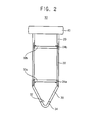
- FIG. 2 is a cross-sectional view illustrating a separating part installed in a tube of the separation container in FIG. 1 .
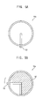
- FIG. 3A and 3B are plan views illustrating a separation layer in FIG. 2 .
- a separation container 10 may include a separation tube 20, a first sedimentation part 30 connected to an end portion of the tube 20, and a separating part provided in the tube 20.
- the separation tube 20 may be a cylindrical tube extending in a longitudinal direction thereof to receive a sample such as flood therein.
- a scale mark may be printed on an outer surface of the separation tube 20.
- the first sedimentation part 30 may be detachably combined with the end portion of the tube 20.
- the first sedimentation part 30 may be combined with the end portion of the tube 20 in a screw connection manner.
- the first sedimentation part 30 may be formed integrally with the tube 20.
- the separation container 10 may further include a capping part 40 connected to another end of the tube 20. After the capping part 40 is removed from the tube 20, the sample may be injected into the tube 20. A surface treatment may be performed on an inner surface of the separation container 10 to change surface characteristics, in order to increase or decrease an adhesive strength or induce a biochemical reaction.
- the tube 20 may be connected to a rotating means such as a rotor of a centrifuge or an agitating means of an agitator such that the tube 20 may move along a linear or curved path to perform a separation therein.
- the first sedimentation part 30 may serve as a distal end portion of the separation tube 20 during centrifugal or agitating separation. Some particles may be deposited in the first sedimentation part 30 under the tube 20 by centrifugal or agitating separation.
- an outlet 32 may be provided in a distal end portion of the first sedimentation part 30 for discharging the deposited particles.
- a sealing cap 34 may be combined with the outlet 32 in a screw connection manner. Accordingly, after centrifugal or agitating separation, the sealing cap 34 may be removed from the outlet 32, and then, the sediment or upper and lower multi layers separated from the sample may be discharged through the outlet 32 of the first sedimentation part 30.
- the separating part may include at least one separating layer 50a, 50b which opens and closes the tube 20 to form a boundary layer within the tube 20 for selectively blocking a flow of the sample.
- the separating layer 50a, 50b may open the tube 20.
- the separating layer 50a, 50b may close the tube 20 to form the boundary layer.
- the separating layer 50a, 50b may be installed to move along the tube 20.
- the separating part may include first and second separating layers 50a, 50b, and first and second holders 24a, 24b respectively supporting the first and second separating layers 50a, 50b.
- the first and second holders 24a, 24b may be installed to move along the tube 20.
- the first and second holders 24a, 24b may be spaced apart from each other along the extending direction of the tube 20.
- the first and second holders 24a, 24b may move along a guide recess 22, which is formed in the inner surface of the tube 20.
- first and second separating layers 50a, 50b may be fixed by the first and second holders 24a, 24b to be spaced apart from each other by a predetermined distance in the tube 20. Additionally, the first and second separating layers 50a, 50b may move relative to each other along the tube 20 to control a distance between the first and second separating layers 50a, 50b.
- the separating layer 50a may include a plurality of unit layers 52 having a structure similar to an aperture mechanism.
- a plurality of the unit layers 52 may be rotated such that the unit layers 52 overlap with each other to close and open the tube 20.
- the unit layers 52 may open the tube 20.
- the unit layers may be rotated by a predetermined angle such that the unit layers 52 may partially or completely close the tube 20 to form the boundary layer for blocking a flow of the sample.
- the unit layers may have various shapes such as circular or arcuate, or polygonal shape when seen in plan view.
- FIGS. 4A and 4B are plan views illustrating a separating layer in accordance with example embodiments.
- a separating layer 50a may include a first unit layer 52a and a second unit layer 52b crossing each other.
- the first and second unit layers 52a, 52b may move in opposite directions such that the first and second unit layers 52a, 52b may cross each other to close the tube 20.
- the first and second unit layers 52a, 52b may be connected to an elastic means (not illustrated). Accordingly, the first and second unit layers 52a, 52b may move in opposite directions to close the tube 20, and may return their original positions by a restitution force of the elastic means.
- the unit layers may be formed using an elastic material to be deformed elastically by an external force.
- the unit layers may have various shapes such as circular or arcuate, or polygonal shape when seen in plan view.
- FIGS. 5A and 5B are plan views illustrating a separating layer in accordance with example embodiments.
- a separating layer 50a may include a unit layer 52 having a structure similar to a folding fan. An end portion of the unit layer 52 may be fixed and another end portion of the unit layer 52 may be connected to a control member 53. Accordingly, as the control member 53 is rotated in a circumferential direction, the unit layer 52 may be unfolded to close the tube 20.
- FIGS. 6A to 6C are plan views illustrating a separating layer in accordance with example embodiments.
- a separating layer 50a may include a first filter layer 54 and a second filter layer 55.
- the first filter layer 54 may have a plurality of first holes 56 and the second filter layer 55 may have a plurality of second holes 57.
- the first filter layer 54 and the second filter layer 55 may be disposed to overlap with each other.
- the first and second filter layers 56, 57 may move (translate, rotate) relative to each other to control a size of a third hole which is formed by the overlapped first and second holes 56, 57.
- the separating layer 50a may serve as a filter for selectively passing a particle of a sample.
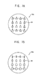
- FIGS. 7A and 7B are plan views illustrating a separating layer in accordance with example embodiments.
- a separating layer 50a may include at least two filter layers which are arranged to overlap with each other.
- the filter layers may have a plurality of holes respectively.
- the holes of the filter layers may correspond to each other.
- the holes of the different filter layers may have various shapes and sizes. Accordingly, holes 58 formed by the overlapped holes may have various shapes and sizes.
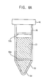
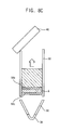
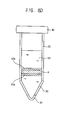
- FIGS. 8A to 8E are cross-sectional views illustrating a separation method in accordance with example embodiments.
- a sample S1 is injected into a separation tube 20.
- First and second separating layers 50a, 50b may be spaced apart from each other by a predetermined distance along an extending direction of the tube 20.
- the first and second separating layers 50a, 50b may be used to divide a target layer A from the separated layers.
- the tube 20 may be connected to a rotating means such as a rotor of a centrifuge or an agitating means of an agitator and then the tube 20 may be moved along a linear or curved path to perform a first separation process.
- a rotating means such as a rotor of a centrifuge or an agitating means of an agitator
- the tube 20 may be moved along a linear or curved path to perform a first separation process.
- the separating layers 50a, 50b may be in an open state. That is, the first and second separating layers 50a, 50b may open the tube 20 to allow the sample to pass through the separating layers. Accordingly, the sample S1 may be separated into a plurality of the layers by the first separation process.
- the first and second separating layers 50a, 50b may be moved to divide the target layer A from the layers.
- the target layer A may be separated to be first positioned between the first and second separating layers 50a, 50b.
- the first separating layer 50a in an open state may move up toward the target layer A
- the second separating layer 50b in an open state may move down toward the target layer B.
- the first and second layers 50a, 50b may be changed into a closed state to block a flow of the sample such that the target layer A may be isolated and surrounded between the first and second separating layers 50a, 50b fixed by the holders. Then, the other layers divided from the sample may be discharged to outside.
- a second separation is performed to separate the target layer A into a plurality of layers.
- the tube 20 may be rotated to perform a second separation process.
- the separating layers 50a, 50b may be in an open state. That is, the first and second separating layers 50a, 50b may open the tube 20 to allow the sample to pass through the separating layers. Accordingly, the target layer A may be separated into a plurality of the layers B, C, P by the second separation process.
- the first separating layer 50a in an open state may move downward and the second separating layer 50b in an open state may move upward. Then, the tube 20 may be rotated or agitated along a linear or curved path to perform the second separation process.
- these processes may be repeated to perform multiple centrifuge or agitating separation, thereby separating and extracting desired layers (particles). Accordingly, after centrifugal or agitating separation is performed to separate layers (particles), without an intermediate process such as fluid transfer process and using an additional separatioin container, the centrifugal or agitating separation may be performed again to thereby improve purity and efficiency of particle separation. Further, the separation container may be used to separate a layer/particle based on particle density, particle size, particle shape or a combination thereof.
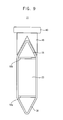
- FIG. 9 is a cross-sectional view illustrating a separation container in accordance with example embodiments.
- the separation container is substantially the same as the separation container described with reference to FIG. 1 except for a second sedimentation part.
- the same reference numerals will be used to refer to the same or like elements and any further repetitive explanation concerning the above elements will be omitted.
- a separation container 11 may further include a second sedimentation part 35 connected to another end portion of a separation tube 20.
- the second sedimentation part 35 may be detachably combined with another end portion of the tube 20.
- the second sedimentation part 35 may be combined with another end portion of the tube 20 in a screw connection manner.
- a capping part 40 may be connected to the second sedimentation part 35 by a connection member 45.
- one of the first and second sedimentation parts 30, 35 may serve as a distal end portion of the separation tube 20 during centrifugal or agitating separation, and the other of the first and second sedimentation parts 30, 35 may serve as an adjacent end portion of the separation tube 20 to opposite to the distal end portion.
- the separation container 11 may be used to perform bidirectional centrifugal or agitating separation, thereby improving purity of layer (particle) separation.
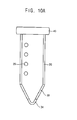
- FIGS. 10A and 10B are cross-sectional views illustrating a separation tube in accordance with example embodiments.
- a separation tube 20 may have a plurality of input/output openings 26 for extracting layers (particles) separated from a target layer or injecting a medium such as a density gradient solution into the target layer.
- the input/output openings 26 may be formed to be spaced apart from each other along an extending direction of the tube 20.
- a separation tube 20 may have an input/output slit 28 for extracting layers (particles) separated from a target layer or injecting a medium such as a density gradient solution into the target layer.
- the input/output slit 28 may be formed to extend in an extending direction of the tube 20.
- an opening/closing member may be further provided to open and close the input/output slit 28.
- FIG. 11 is a cross-sectional view illustrating a jig for manipulating the separation container in FIG. 1 .
- a separation tube 20 may be detachably mounted on a fixing jig 100.
- a plunger 102 may be used to apply pressure (positive pressure/negative pressure) to single or multi layers in the separation tube 20 such that a desired layer may be selectively collected in a direction of applying pressure.
Landscapes
- Chemical & Material Sciences (AREA)
- Health & Medical Sciences (AREA)
- Chemical Kinetics & Catalysis (AREA)
- Analytical Chemistry (AREA)
- General Health & Medical Sciences (AREA)
- Hematology (AREA)
- Clinical Laboratory Science (AREA)
- Centrifugal Separators (AREA)
Abstract
Description
- This application claims priority under 35 USC § 119 to Korean Patent Application No.
2012-0053892, filed on May 21, 2012 2013-0016406, filed on February 15, 2013 - Example embodiments relate to a particle separation container and a particle separation method using the same. More particularly, example embodiments relate to a separation container for centrifuge or agitator and a particle separation method using the same.
- A centrifuge is a piece of equipment that separates a material using a centrifugal force generated when an object rotates. A mixed fluid such as blood may be separated into a plurality of layers by a centrifuge.
- When the separated layers by the centrifuge are repeatedly separated by a centrifuge, an additional container for centrifuge and a fluid transfer process may be necessarily required, resulting loss of the particles. Further, similar problems may occur when the separated layer (particle) is extracted.
- An agitator is a device to stir or shake something such as fluid and fluid, fluid and solid, powder, etc. As a fluid including particles having different sizes is agiated continuously by the agitator, the particles in the fluid may be induced to move in a specific direction.
- Further, when a fluid including particles having different sizes is injected onto a filter and is agitated continuously, the filter may be prevented from being blocked by a particle layer having a relatively high density and relatively smller particles may be prevented from being congested by a previously filtered particle having a relatively greater size in early separation stage. However, even though in this case, in order to separate again remaining particles after filtering specific particles by an agitating force, an additional filter exchanger and a fluid transfer process may be necessarily required, resulting loss of the particles. Further, similar problems may occur when the separated particles are extracted.
- Example embodiments provide a separation container capable of performing continuous centrifuge or agitating separations.
- Example embodiments provide a particle separation method using the above separation container.
- According to example embodiments, a separation container includes a separation tube receiving a sample therein, a first sedimentation part connected to an end portion of the tube, a particle in the sample being deposited by a centrifugal or agitating force, and a separating part provided in the tube and including at least one separating layer which selectively opens and closes the tube.
- In example embodiments, the separating layer may close the tube to form a boundary layer within the tube for controlling a flow of the sample through the separating layer.
- In example embodiments, the separating layer may be installed to move along the tube.
- In example embodiments, the separating part may include first and second holders installed movable along the tube and spaced apart from each other along an extending direction of the tube, and first and second separating layers supported respectively by the first and second holders.
- In example embodiments, a guide recess may be formed in an inner surface of the tube and the first and second holders move along the guide recess.
- In example embodiments, the separating layer may include at least two unit layers which cross each other to open and close the tube.
- In example embodiments, the unit layer may include an elastic material to be deformed elastically by an external force.
- In example embodiments, the separating layer may include at least two filter layers which are disposed to overlap with each other, the filter layer having a plurality of holes.
- In example embodiments, the filter layers may move relative to each other to control an effective size or shape of a hole which is formed by the overlapped holes of the filter layers.
- In example embodiments, the first sedimentation part may be detachably combined with the end portion of the tube.
- In example embodiments, the first sedimentation part may include an outlet for discharging the deposited particles.
- In example embodiments, the tube may have an opening for collecting separated particles or injecting a medium.
- In example embodiments, the separation container may further include a capping part connected to another end of the tube.
- In example embodiments, the separation container may further include a second sedimentation part connected to another end portion of the tube.
- In example embodiments, the tube may be detachably mounted on a fixing jig, and a particle separated by the separating part is collected using a plunger which applies positive or negative pressure into the tube.
- According to example embodiments, in a particle separation method, a separation container is provided, the separation container comprising a separation tube, a first sedimentation part connected to an end portion of the tube, and a separating part provided in the tube and including at least one separating layer which selectively opens and closes the tube. A sample is injected into the tube. The tube is rotated or agitated to perform a first centrifuge or agitating separation such that the sample is separated into a plurality of layers. The separating layer may be used to divide a target layer from the separated layers. The tube is rotated or agitated to perform a second centrifuge or agitating separation such that the target layer is separated into a plurality of layers.
- In example embodiments, performing the first centrifuge or agitating separation may include rotating or agitating the tube, with the tube being open by the separating layer.
- In example embodiments, dividing the target layer may include isolating and surrounding the target layer by the separating layer, with the tube being closed by the separating layer.
- In example embodiments, separating the target layer may further include moving the separating layer along the tube, with the tube being closed by the separating layer.
- In example embodiments, the method may further include collecting the separated layer in the separation tube, the separation tube being fixed by a fixing jig.
- According to example embodiments, a separation container may include at least one separating part provided in a separation tube and a sedimentation part connected to an end portion of the tube. The separating part, the sedimentation part and a combination thereof may be used to perform multiple centrifugal or agitating separation in one separation tube to separate and extract a desired layer (particles).
- Accordingly, the layers (particles) by a centrifugal or agitating force may be separated repeatedly by the centrifugal or agitating separation, without an intermediate process such as fluid transfer process and using an additional separatioin container, to thereby improve purity and efficiency of particle separation. Further, the separation container may be used to separate a layer/particle based on particle density, particle size, particle shape or a combination thereof.
- Example embodiments will be more clearly understood from the following detailed description taken in conjunction with the accompanying drawings.
FIGS. 1 to 11 represent non-limiting, example embodiments as described herein. -
FIG. 1 is a view illustrating a separation container in accordance with example embodiments. -
FIG. 2 is a cross-sectional view illustrating a separating part installed in a tube of the separation container inFIG. 1 . -
FIG. 3A and 3B are plan views illustrating a separation layer inFIG. 2 . -
FIGS. 4A and 4B are plan views illustrating a separating layer in accordance with example embodiments. -
FIGS. 5A and 5B are plan views illustrating a separating layer in accordance with example embodiments. -
FIGS. 6A to 6C are plan views illustrating a separating layer in accordance with example embodiments. -
FIGS. 7A and 7B are plan views illustrating a separating layer in accordance with example embodiments. -
FIGS. 8A to 8E are cross-sectional views illustrating a separation method in accordance with example embodiments. -
FIG. 9 is a cross-sectional view illustrating a separation container in accordance with example embodiments. -
FIGS. 10A and10B are cross-sectional views illustrating a separation tube in accordance with example embodiments. -
FIG. 11 is a cross-sectional view illustrating a jig for manipulating the separation container inFIG. 1 . - Various example embodiments will be described more fully hereinafter with reference to the accompanying drawings, in which some example embodiments are shown. The present inventive concept may, however, be embodied in many different forms and should not be construed as limited to the example embodiments set forth herein. Rather, these example embodiments are provided so that this description will be thorough and complete, and will fully convey the scope of the present inventive concept to those skilled in the art. In the drawings, the sizes and relative sizes of layers and regions may be exaggerated for clarity.
- It will be understood that when an element or layer is referred to as being "on," "connected to" or "coupled to" another element or layer, it can be directly on, connected or coupled to the other element or layer or intervening elements or layers may be present. In contrast, when an element is referred to as being "directly on," "directly connected to" or "directly coupled to" another element or layer, there are no intervening elements or layers present. Like numerals refer to like elements throughout. As used herein, the term "and/or" includes any and all combinations of one or more of the associated listed items.
- It will be understood that, although the terms first, second, third, fourth etc. may be used herein to describe various elements, components, regions, layers and/or sections, these elements, components, regions, layers and/or sections should not be limited by these terms. These terms are only used to distinguish one element, component, region, layer or section from another region, layer or section. Thus, a first element, component, region, layer or section discussed below could be termed a second element, component, region, layer or section without departing from the teachings of the present inventive concept.
- Spatially relative terms, such as "beneath," "below," "lower," "above," "upper" and the like, may be used herein for ease of description to describe one element or feature's relationship to another element(s) or feature(s) as illustrated in the figures. It will be understood that the spatially relative terms are intended to encompass different orientations of the device in use or operation in addition to the orientation depicted in the figures. For example, if the device in the figures is turned over, elements described as "below" or "beneath" other elements or features would then be oriented "above" the other elements or features. Thus, the exemplary term "below" can encompass both an orientation of above and below. The device may be otherwise oriented (rotated 90 degrees or at other orientations) and the spatially relative descriptors used herein interpreted accordingly.
- The terminology used herein is for the purpose of describing particular example embodiments only and is not intended to be limiting of the present inventive concept. As used herein, the singular forms "a," "an" and "the" are intended to include the plural forms as well, unless the context clearly indicates otherwise. It will be further understood that the terms "comprises" and/or "comprising," when used in this specification, specify the presence of stated features, integers, steps, operations, elements, and/or components, but do not preclude the presence or addition of one or more other features, integers, steps, operations, elements, components, and/or groups thereof.
- Example embodiments are described herein with reference to cross-sectional illustrations that are schematic illustrations of idealized example embodiments (and intermediate structures). As such, variations from the shapes of the illustrations as a result, for example, of manufacturing techniques and/or tolerances, are to be expected. Thus, example embodiments should not be construed as limited to the particular shapes of regions illustrated herein but are to include deviations in shapes that result, for example, from manufacturing.
- Unless otherwise defined, all terms (including technical and scientific terms) used herein have the same meaning as commonly understood by one of ordinary skill in the art to which this inventive concept belongs. It will be further understood that terms, such as those defined in commonly used dictionaries, should be interpreted as having a meaning that is consistent with their meaning in the context of the relevant art and will not be interpreted in an idealized or overly formal sense unless expressly so defined herein.
-
FIG. 1 is a view illustrating a separation container in accordance with example embodiments.FIG. 2 is a cross-sectional view illustrating a separating part installed in a tube of the separation container inFIG. 1 .FIG. 3A and 3B are plan views illustrating a separation layer inFIG. 2 . - Referring to
FIGS. 1 to 3B , aseparation container 10 may include aseparation tube 20, afirst sedimentation part 30 connected to an end portion of thetube 20, and a separating part provided in thetube 20. - In example embodiments, the
separation tube 20 may be a cylindrical tube extending in a longitudinal direction thereof to receive a sample such as flood therein. A scale mark may be printed on an outer surface of theseparation tube 20. Thefirst sedimentation part 30 may be detachably combined with the end portion of thetube 20. For example, thefirst sedimentation part 30 may be combined with the end portion of thetube 20 in a screw connection manner. Alternatively, thefirst sedimentation part 30 may be formed integrally with thetube 20. - The
separation container 10 may further include acapping part 40 connected to another end of thetube 20. After thecapping part 40 is removed from thetube 20, the sample may be injected into thetube 20. A surface treatment may be performed on an inner surface of theseparation container 10 to change surface characteristics, in order to increase or decrease an adhesive strength or induce a biochemical reaction. - The
tube 20 may be connected to a rotating means such as a rotor of a centrifuge or an agitating means of an agitator such that thetube 20 may move along a linear or curved path to perform a separation therein. Thefirst sedimentation part 30 may serve as a distal end portion of theseparation tube 20 during centrifugal or agitating separation. Some particles may be deposited in thefirst sedimentation part 30 under thetube 20 by centrifugal or agitating separation. - In example embodiments, an
outlet 32 may be provided in a distal end portion of thefirst sedimentation part 30 for discharging the deposited particles. For example, a sealingcap 34 may be combined with theoutlet 32 in a screw connection manner. Accordingly, after centrifugal or agitating separation, the sealingcap 34 may be removed from theoutlet 32, and then, the sediment or upper and lower multi layers separated from the sample may be discharged through theoutlet 32 of thefirst sedimentation part 30. - The separating part may include at least one
separating layer tube 20 to form a boundary layer within thetube 20 for selectively blocking a flow of the sample. When thetube 20 is rotated or moved along a linear or curved path, theseparating layer tube 20. When thetube 20 is stopped, theseparating layer tube 20 to form the boundary layer. Theseparating layer tube 20. - In example embodiments, as illustrated in
FIG. 2 , the separating part may include first andsecond separating layers second holders second separating layers second holders tube 20. The first andsecond holders tube 20. For example, the first andsecond holders guide recess 22, which is formed in the inner surface of thetube 20. - Accordingly, the first and
second separating layers second holders tube 20. Additionally, the first andsecond separating layers tube 20 to control a distance between the first andsecond separating layers - As illustrated in
FIGS. 3A and 3B , theseparating layer 50a may include a plurality of unit layers 52 having a structure similar to an aperture mechanism. A plurality of the unit layers 52 may be rotated such that the unit layers 52 overlap with each other to close and open thetube 20. For example, as illustrated inFIG. 3A , when thetube 20 is rotated or moved along a linear or curved path during centrifugal or agitating separation, the unit layers 52 may open thetube 20. As illustrated inFIG. 3B , when thetube 20 is stopped after centrifugal or agitating separation, the unit layers may be rotated by a predetermined angle such that the unit layers 52 may partially or completely close thetube 20 to form the boundary layer for blocking a flow of the sample. The unit layers may have various shapes such as circular or arcuate, or polygonal shape when seen in plan view. -
FIGS. 4A and 4B are plan views illustrating a separating layer in accordance with example embodiments. - Referring to
FIGS. 4A and 4B , aseparating layer 50a may include afirst unit layer 52a and asecond unit layer 52b crossing each other. The first and second unit layers 52a, 52b may move in opposite directions such that the first and second unit layers 52a, 52b may cross each other to close thetube 20. The first and second unit layers 52a, 52b may be connected to an elastic means (not illustrated). Accordingly, the first and second unit layers 52a, 52b may move in opposite directions to close thetube 20, and may return their original positions by a restitution force of the elastic means. Alternatively, the unit layers may be formed using an elastic material to be deformed elastically by an external force. The unit layers may have various shapes such as circular or arcuate, or polygonal shape when seen in plan view. -
FIGS. 5A and 5B are plan views illustrating a separating layer in accordance with example embodiments. - Referring to
FIGS. 5A and 5B , aseparating layer 50a may include aunit layer 52 having a structure similar to a folding fan. An end portion of theunit layer 52 may be fixed and another end portion of theunit layer 52 may be connected to acontrol member 53. Accordingly, as thecontrol member 53 is rotated in a circumferential direction, theunit layer 52 may be unfolded to close thetube 20. -
FIGS. 6A to 6C are plan views illustrating a separating layer in accordance with example embodiments. - Referring to
FIGS. 6A to 6C , aseparating layer 50a may include afirst filter layer 54 and asecond filter layer 55. Thefirst filter layer 54 may have a plurality offirst holes 56 and thesecond filter layer 55 may have a plurality ofsecond holes 57. Thefirst filter layer 54 and thesecond filter layer 55 may be disposed to overlap with each other. As illustrated inFIGS. 6B and 6C , the first and second filter layers 56, 57 may move (translate, rotate) relative to each other to control a size of a third hole which is formed by the overlapped first andsecond holes separating layer 50a may serve as a filter for selectively passing a particle of a sample. -
FIGS. 7A and 7B are plan views illustrating a separating layer in accordance with example embodiments. - Referring to
FIGS. 7A and 7B , aseparating layer 50a may include at least two filter layers which are arranged to overlap with each other. The filter layers may have a plurality of holes respectively. The holes of the filter layers may correspond to each other. The holes of the different filter layers may have various shapes and sizes. Accordingly, holes 58 formed by the overlapped holes may have various shapes and sizes. - Hereinafter, a method of processing a particle using the separation container in
FIG. 1 will be explained. -
FIGS. 8A to 8E are cross-sectional views illustrating a separation method in accordance with example embodiments. - Referring to
FIG. 8A , a sample S1 is injected into aseparation tube 20. - In example embodiments, after a
capping part 40 is removed from thetube 20, the sample S1 such as blood may be injected into thetube 20. First andsecond separating layers tube 20. - Referring to
FIGS. 8B and8C , after a first centrifugal separation or agitating separation is performed to separate the sample S1 into a plurality of layers, the first andsecond separating layers - The
tube 20 may be connected to a rotating means such as a rotor of a centrifuge or an agitating means of an agitator and then thetube 20 may be moved along a linear or curved path to perform a first separation process. When thetube 20 is rotated for the first separation process, the separatinglayers second separating layers tube 20 to allow the sample to pass through the separating layers. Accordingly, the sample S1 may be separated into a plurality of the layers by the first separation process. - Then, the first and
second separating layers second separating layers first separating layer 50a in an open state may move up toward the target layer A, and thesecond separating layer 50b in an open state may move down toward the target layer B. - As illustrated in
FIG. 8C , when the target layer A is positioned between the first andsecond separating layers second layers second separating layers - Referring to
FIGS. 8D and8E , after a solution S2 is injected into theseparation tube 20, a second separation is performed to separate the target layer A into a plurality of layers. - After the solution S2 such as a homogeneous solution or density gradient medium may be injected into the
tube 20, thetube 20 may be rotated to perform a second separation process. When thetube 20 is rotated for the second separation process, the separatinglayers second separating layers tube 20 to allow the sample to pass through the separating layers. Accordingly, the target layer A may be separated into a plurality of the layers B, C, P by the second separation process. - For example, after the solution S2 is injected into the
tube 20, thefirst separating layer 50a in an open state may move downward and thesecond separating layer 50b in an open state may move upward. Then, thetube 20 may be rotated or agitated along a linear or curved path to perform the second separation process. - As medntion above, these processes may be repeated to perform multiple centrifuge or agitating separation, thereby separating and extracting desired layers (particles). Accordingly, after centrifugal or agitating separation is performed to separate layers (particles), without an intermediate process such as fluid transfer process and using an additional separatioin container, the centrifugal or agitating separation may be performed again to thereby improve purity and efficiency of particle separation. Further, the separation container may be used to separate a layer/particle based on particle density, particle size, particle shape or a combination thereof.
-
FIG. 9 is a cross-sectional view illustrating a separation container in accordance with example embodiments. The separation container is substantially the same as the separation container described with reference toFIG. 1 except for a second sedimentation part. Thus, the same reference numerals will be used to refer to the same or like elements and any further repetitive explanation concerning the above elements will be omitted. - Referring to
FIG. 9 , aseparation container 11 may further include asecond sedimentation part 35 connected to another end portion of aseparation tube 20. - The
second sedimentation part 35 may be detachably combined with another end portion of thetube 20. Thesecond sedimentation part 35 may be combined with another end portion of thetube 20 in a screw connection manner. A cappingpart 40 may be connected to thesecond sedimentation part 35 by aconnection member 45. - Accordingly, one of the first and
second sedimentation parts separation tube 20 during centrifugal or agitating separation, and the other of the first andsecond sedimentation parts separation tube 20 to opposite to the distal end portion. Thus, theseparation container 11 may be used to perform bidirectional centrifugal or agitating separation, thereby improving purity of layer (particle) separation. -
FIGS. 10A and10B are cross-sectional views illustrating a separation tube in accordance with example embodiments. - Referring to
FIG. 10A , aseparation tube 20 may have a plurality of input/output openings 26 for extracting layers (particles) separated from a target layer or injecting a medium such as a density gradient solution into the target layer. The input/output openings 26 may be formed to be spaced apart from each other along an extending direction of thetube 20. - Referring to
FIG. 10B , aseparation tube 20 may have an input/output slit 28 for extracting layers (particles) separated from a target layer or injecting a medium such as a density gradient solution into the target layer. The input/output slit 28 may be formed to extend in an extending direction of thetube 20. Although it is not illustrated in the figure, an opening/closing member may be further provided to open and close the input/output slit 28. -
FIG. 11 is a cross-sectional view illustrating a jig for manipulating the separation container inFIG. 1 . - Referring to
FIG. 11 , aseparation tube 20 may be detachably mounted on a fixingjig 100. Aplunger 102 may be used to apply pressure (positive pressure/negative pressure) to single or multi layers in theseparation tube 20 such that a desired layer may be selectively collected in a direction of applying pressure. - The foregoing is illustrative of example embodiments and is not to be construed as limiting thereof. Although a few example embodiments have been described, those skilled in the art will readily appreciate that many modifications are possible in the example embodiments without materially departing from the novel teachings and advantages of the present inventive concept. Accordingly, all such modifications are intended to be included within the scope of the present inventive concept as defined in the claims. In the claims, means-plus-function clauses are intended to cover the structures described herein as performing the recited function and not only structural equivalents but also equivalent structures. Therefore, it is to be understood that the foregoing is illustrative of various example embodiments and is not to be construed as limited to the specific example embodiments disclosed, and that modifications to the disclosed example embodiments, as well as other example embodiments, are intended to be included within the scope of the appended claims.
Claims (20)
- A separation container, comprising:a separation tube receiving a sample therein;a first sedimentation part connected to an end portion of the tube, a particle in the sample being deposited by a centrifugal or agitating force; anda separating part provided in the tube and including at least one separating layer which selectively opens and closes the tube.
- The separation container of claim 1, wherein the separating layer closes the tube to form a boundary layer within the tube for controlling a flow of the sample through the separating layer.
- The separation container of claim 1, wherein the separating layer is installed to move along the tube.
- The separation container of claim 1, wherein the separating part comprises first and second holders installed movable along the tube and spaced apart from each other along an extending direction of the tube; and
first and second separating layers supported respectively by the first and second holders. - The separation container of claim 4, wherein a guide recess is formed in an inner surface of the tube and the first and second holders move along the guide recess.
- The separation container of claim 1, wherein the separating layer comprises at least two unit layers which cross each other to open and close the tube.
- The separation container of claim 6, wherein the unit layer includes an elastic material to be deformed elastically by an external force.
- The separation container of claim 1, wherein the separating layer comprises at least two filter layers which are disposed to overlap with each other, the filter layer having a plurality of holes.
- The separation container of claim 8, wherein the filter layers move relative to each other to control an effective size or shape of a hole which is formed by the overlapped holes of the filter layers.
- The separation container of claim 1, wherein the first sedimentation part is detachably combined with the end portion of the tube.
- The separation container of claim 1, wherein the first sedimentation part comprises an outlet for discharging the deposited particles.
- The separation container of claim 1, wherein the tube has an opening for collecting separated particles or injecting a medium.
- The separation container of claim 1, further comprising a capping part connected to another end of the tube.
- The separation container of claim 1, further comprising a second sedimentation part connected to another end portion of the tube.
- The separation container of claim 1, wherein the tube is detachably mounted on a fixing jig, and a particle separated by the separating part is collected using a plunger which applies positive or negative pressure into the tube.
- A particle separation method, comprising;
providing a separation container, the separation container comprising a separation tube, a first sedimentation part connected to an end portion of the tube, and a separating part provided in the tube and including at least one separating layer which selectively opens and closes the tube;
injecting a sample into the tube;
rotating or agitating the tube to perform a first centrifuge or agitating separation such that the sample is separated into a plurality of layers;
using the separating layer to divide a target layer from the separated layers; and rotating or agitating the tube to perform a second centrifuge or agitating separation such that the target layer is separated into a plurality of layers. - The method of claim 16, wherein performing the first centrifuge or agitating separation comprises rotating or agitating the tube, with the tube being open by the separating layer.
- The method of claim 16, wherein dividing the target layer comprises isolating and surrounding the target layer by the separating layer, with the tube being closed by the separating layer.
- The method of claim 18, wherein dividing the target layer further comprises moving the separating layer along the tube, with the tube being closed by the separating layer.
- The method of claim 16, further comprising collecting the separated layer in the separation tube, the separation tube being fixed by a fixing jig.
Applications Claiming Priority (3)
| Application Number | Priority Date | Filing Date | Title |
|---|---|---|---|
| KR20120053892 | 2012-05-21 | ||
| KR1020130016406A KR101459109B1 (en) | 2012-05-21 | 2013-02-15 | Container for multiple centrifugation and Particle Separation Method Using the Same |
| PCT/KR2013/002966 WO2013176400A1 (en) | 2012-05-21 | 2013-04-09 | Separation container for continuously separating particle/layer and method for separating particle/layer by using same |
Publications (3)
| Publication Number | Publication Date |
|---|---|
| EP2853310A1 true EP2853310A1 (en) | 2015-04-01 |
| EP2853310A4 EP2853310A4 (en) | 2016-02-24 |
| EP2853310B1 EP2853310B1 (en) | 2018-09-12 |
Family
ID=49856340
Family Applications (1)
| Application Number | Title | Priority Date | Filing Date |
|---|---|---|---|
| EP13793579.7A Not-in-force EP2853310B1 (en) | 2012-05-21 | 2013-04-09 | Separation container for continuously separating particle/layer and method for separating particle/layer by using same |
Country Status (4)
| Country | Link |
|---|---|
| US (1) | US9802194B2 (en) |
| EP (1) | EP2853310B1 (en) |
| KR (1) | KR101459109B1 (en) |
| WO (1) | WO2013176400A1 (en) |
Cited By (1)
| Publication number | Priority date | Publication date | Assignee | Title |
|---|---|---|---|---|
| CN106179552A (en) * | 2016-07-06 | 2016-12-07 | 江苏科华医疗器械科技有限公司 | A kind of integral type ultra-filtration centrifuge tube |
Families Citing this family (6)
| Publication number | Priority date | Publication date | Assignee | Title |
|---|---|---|---|---|
| EP3386391B1 (en) * | 2015-12-11 | 2020-11-25 | Babson Diagnostics, Inc. | Specimen container and method for separating serum or plasma from whole blood |
| US20190331703A1 (en) | 2016-11-14 | 2019-10-31 | Siemens Healthcare Diagnostics Inc. | Sample preparation device |
| US12050052B1 (en) | 2021-08-06 | 2024-07-30 | Babson Diagnostics, Inc. | Refrigerated carrier device for biological samples |
| WO2023196922A1 (en) | 2022-04-06 | 2023-10-12 | Babson Diagnostics, Inc. | Automated centrifuge loader |
| CN118371342A (en) * | 2023-08-31 | 2024-07-23 | 内蒙古中普检验检测有限公司 | Serum cholinesterase extraction device and extraction method |
| KR102845175B1 (en) * | 2023-11-02 | 2025-08-12 | 주식회사 코리아노바 | Insect hatching assist device, insect egg-laying assist device, insect hatching and egg-laying assist device and automatic caterpillar breeding system including the same |
Family Cites Families (20)
| Publication number | Priority date | Publication date | Assignee | Title |
|---|---|---|---|---|
| US3512940A (en) * | 1968-12-30 | 1970-05-19 | Justin J Shapiro | Test tube filter device |
| US3954614A (en) * | 1972-07-31 | 1976-05-04 | Glasrock Products, Inc. | Serum skimmer and filter separation unit |
| DE2415618C3 (en) * | 1974-03-30 | 1978-06-22 | Walter Sarstedt Kunststoff-Spritzgusswerk, 5223 Nuembrecht | Filter device for separating blood fractions |
| CA1074273A (en) * | 1976-05-06 | 1980-03-25 | Sherwood Medical Industries Inc. | Phase separation device |
| US5560830A (en) * | 1994-12-13 | 1996-10-01 | Coleman; Charles M. | Separator float and tubular body for blood collection and separation and method of use thereof |
| US5860937A (en) * | 1997-04-30 | 1999-01-19 | Becton, Dickinson & Company | Evacuated sample collection tube with aqueous additive |
| JP3972528B2 (en) * | 1999-08-27 | 2007-09-05 | 宇部興産株式会社 | Fluid separation membrane module and separation method |
| US6471069B2 (en) * | 1999-12-03 | 2002-10-29 | Becton Dickinson And Company | Device for separating components of a fluid sample |
| US20060278588A1 (en) * | 2002-05-24 | 2006-12-14 | Woodell-May Jennifer E | Apparatus and method for separating and concentrating fluids containing multiple components |
| JP2004180551A (en) * | 2002-12-02 | 2004-07-02 | Arkray Inc | Method for collecting microorganism and method for amplifying or detecting gene using the same |
| KR100491084B1 (en) * | 2002-12-23 | 2005-05-24 | 이광섭 | Block for key reproduction |
| AT414322B (en) * | 2004-11-29 | 2007-03-15 | Greiner Bio One Gmbh | SEPARATING DEVICE, ESPECIALLY FOR BODY FLUIDS, AND RECORDING EQUIPMENT WITH SUCH A SEPARATING DEVICE |
| KR100861429B1 (en) * | 2006-08-25 | 2008-10-02 | 코아바이오시스템 주식회사 | Plasmid DNA Filter Tube Kit |
| EP2303457B1 (en) * | 2008-07-21 | 2019-08-28 | Becton, Dickinson and Company | Density phase separation device |
| KR101087653B1 (en) | 2008-11-13 | 2011-11-30 | 이희영 | Preparing for prp |
| US8383419B2 (en) * | 2009-06-16 | 2013-02-26 | Robert A. Levine | Harvesting target materials from centrifuged suspensions |
| KR101188660B1 (en) * | 2010-07-08 | 2012-10-08 | 주식회사 무한기업 | Test tube used in the centrifugal separator |
| KR101254675B1 (en) * | 2010-10-25 | 2013-04-15 | 주식회사 싸이토젠 | Cells collection apparatus |
| KR200455871Y1 (en) * | 2011-05-18 | 2011-09-29 | 박재우 | Blood separator |
| JP3172219U (en) | 2011-09-27 | 2011-12-08 | 学校法人星薬科大学 | Centrifuge tube |
-
2013
- 2013-02-15 KR KR1020130016406A patent/KR101459109B1/en not_active Expired - Fee Related
- 2013-04-09 US US14/402,885 patent/US9802194B2/en not_active Expired - Fee Related
- 2013-04-09 EP EP13793579.7A patent/EP2853310B1/en not_active Not-in-force
- 2013-04-09 WO PCT/KR2013/002966 patent/WO2013176400A1/en not_active Ceased
Cited By (1)
| Publication number | Priority date | Publication date | Assignee | Title |
|---|---|---|---|---|
| CN106179552A (en) * | 2016-07-06 | 2016-12-07 | 江苏科华医疗器械科技有限公司 | A kind of integral type ultra-filtration centrifuge tube |
Also Published As
| Publication number | Publication date |
|---|---|
| KR101459109B1 (en) | 2014-11-12 |
| KR20130129831A (en) | 2013-11-29 |
| WO2013176400A1 (en) | 2013-11-28 |
| US9802194B2 (en) | 2017-10-31 |
| EP2853310B1 (en) | 2018-09-12 |
| US20150151294A1 (en) | 2015-06-04 |
| EP2853310A4 (en) | 2016-02-24 |
Similar Documents
| Publication | Publication Date | Title |
|---|---|---|
| US9802194B2 (en) | Container for multiple particle/layer separations and particle/layer separation method using the same | |
| DE102010003223B4 (en) | Device for insertion into a rotor of a centrifuge, centrifuge and method for fluidic coupling of cavities | |
| DE102013203293B4 (en) | Apparatus and method for conducting a liquid through a first or second outlet channel | |
| DE102010041621B4 (en) | Method for transporting magnetic particles | |
| DE60035611T2 (en) | MICRO FLUID ANALYSIS DEVICE | |
| DE102012202775B4 (en) | FLUIDIKMODUL, DEVICE AND METHOD FOR PUMPING A LIQUID | |
| EP2532428B1 (en) | Cartridge, centrifuge and method for mixing a first and a second component | |
| WO2002074438A2 (en) | Structural units that define fluidic functions | |
| EP2532426B1 (en) | Cartridge for insertion into a centrifuge, centrifuge and method | |
| EP1987362A2 (en) | Device and method for treating or cleaning sample material, in particular nucleic acids | |
| US20190022667A1 (en) | Multifunctional biological substance separation device | |
| EP2532427B1 (en) | Cartridge, centrifuge and method | |
| EP2774684B1 (en) | A centrifugal separator | |
| EP2535108A1 (en) | Microfluidic System and method of operating the system | |
| EP1979096A1 (en) | Microfluidic arrangement and modular lab-on-a-chip system | |
| JP6907183B2 (en) | Methods and equipment for sample separation and collection | |
| DE102009005925A1 (en) | Device for handling bio molecules to accomplish immunoassay, has rotary encoder producing relative motion between magnetic force element and channel structure for moving magnetic particles over phase boundary of multiphase flow | |
| WO2018011085A1 (en) | Handling of liquids using a fluid module having a fluid plane that is inclined with respect to a rotation plane | |
| US20180154374A1 (en) | Red blood cell washing system | |
| EP4025344B1 (en) | Microfluidic device with an integrated centrifuge unit for processing liquid samples | |
| DE102012220250A1 (en) | FLUIDIKMODUL FOR A CENTRIFUGAL FILTRATION AND METHOD FOR FILTERING A SAMPLE | |
| DE19634413A1 (en) | Method and device for sorting centrifugation or sorting flow centrifugation | |
| CN202315485U (en) | Feed liquid filtering device | |
| CN207998630U (en) | A kind of Extraction of rare eart extraction separation device | |
| KR102952162B1 (en) | Apparatus and method for simultaneous separation of cells and microparticles |
Legal Events
| Date | Code | Title | Description |
|---|---|---|---|
| PUAI | Public reference made under article 153(3) epc to a published international application that has entered the european phase |
Free format text: ORIGINAL CODE: 0009012 |
|
| 17P | Request for examination filed |
Effective date: 20141210 |
|
| AK | Designated contracting states |
Kind code of ref document: A1 Designated state(s): AL AT BE BG CH CY CZ DE DK EE ES FI FR GB GR HR HU IE IS IT LI LT LU LV MC MK MT NL NO PL PT RO RS SE SI SK SM TR |
|
| AX | Request for extension of the european patent |
Extension state: BA ME |
|
| DAX | Request for extension of the european patent (deleted) | ||
| RA4 | Supplementary search report drawn up and despatched (corrected) |
Effective date: 20160125 |
|
| RIC1 | Information provided on ipc code assigned before grant |
Ipc: B04B 11/00 20060101ALI20160119BHEP Ipc: B04B 7/08 20060101AFI20160119BHEP Ipc: B01L 3/00 20060101ALI20160119BHEP Ipc: B04B 5/02 20060101ALI20160119BHEP |
|
| STAA | Information on the status of an ep patent application or granted ep patent |
Free format text: STATUS: REQUEST FOR EXAMINATION WAS MADE |
|
| R17P | Request for examination filed (corrected) |
Effective date: 20141210 |
|
| GRAP | Despatch of communication of intention to grant a patent |
Free format text: ORIGINAL CODE: EPIDOSNIGR1 |
|
| STAA | Information on the status of an ep patent application or granted ep patent |
Free format text: STATUS: GRANT OF PATENT IS INTENDED |
|
| INTG | Intention to grant announced |
Effective date: 20171220 |
|
| GRAS | Grant fee paid |
Free format text: ORIGINAL CODE: EPIDOSNIGR3 |
|
| GRAA | (expected) grant |
Free format text: ORIGINAL CODE: 0009210 |
|
| STAA | Information on the status of an ep patent application or granted ep patent |
Free format text: STATUS: THE PATENT HAS BEEN GRANTED |
|
| AK | Designated contracting states |
Kind code of ref document: B1 Designated state(s): AL AT BE BG CH CY CZ DE DK EE ES FI FR GB GR HR HU IE IS IT LI LT LU LV MC MK MT NL NO PL PT RO RS SE SI SK SM TR |
|
| REG | Reference to a national code |
Ref country code: GB Ref legal event code: FG4D |
|
| REG | Reference to a national code |
Ref country code: CH Ref legal event code: EP |
|
| REG | Reference to a national code |
Ref country code: IE Ref legal event code: FG4D |
|
| REG | Reference to a national code |
Ref country code: DE Ref legal event code: R096 Ref document number: 602013043601 Country of ref document: DE |
|
| REG | Reference to a national code |
Ref country code: AT Ref legal event code: REF Ref document number: 1039914 Country of ref document: AT Kind code of ref document: T Effective date: 20181015 |
|
| REG | Reference to a national code |
Ref country code: NL Ref legal event code: MP Effective date: 20180912 |
|
| REG | Reference to a national code |
Ref country code: LT Ref legal event code: MG4D |
|
| PG25 | Lapsed in a contracting state [announced via postgrant information from national office to epo] |
Ref country code: FI Free format text: LAPSE BECAUSE OF FAILURE TO SUBMIT A TRANSLATION OF THE DESCRIPTION OR TO PAY THE FEE WITHIN THE PRESCRIBED TIME-LIMIT Effective date: 20180912 Ref country code: GR Free format text: LAPSE BECAUSE OF FAILURE TO SUBMIT A TRANSLATION OF THE DESCRIPTION OR TO PAY THE FEE WITHIN THE PRESCRIBED TIME-LIMIT Effective date: 20181213 Ref country code: SE Free format text: LAPSE BECAUSE OF FAILURE TO SUBMIT A TRANSLATION OF THE DESCRIPTION OR TO PAY THE FEE WITHIN THE PRESCRIBED TIME-LIMIT Effective date: 20180912 Ref country code: RS Free format text: LAPSE BECAUSE OF FAILURE TO SUBMIT A TRANSLATION OF THE DESCRIPTION OR TO PAY THE FEE WITHIN THE PRESCRIBED TIME-LIMIT Effective date: 20180912 Ref country code: LT Free format text: LAPSE BECAUSE OF FAILURE TO SUBMIT A TRANSLATION OF THE DESCRIPTION OR TO PAY THE FEE WITHIN THE PRESCRIBED TIME-LIMIT Effective date: 20180912 Ref country code: NO Free format text: LAPSE BECAUSE OF FAILURE TO SUBMIT A TRANSLATION OF THE DESCRIPTION OR TO PAY THE FEE WITHIN THE PRESCRIBED TIME-LIMIT Effective date: 20181212 Ref country code: BG Free format text: LAPSE BECAUSE OF FAILURE TO SUBMIT A TRANSLATION OF THE DESCRIPTION OR TO PAY THE FEE WITHIN THE PRESCRIBED TIME-LIMIT Effective date: 20181212 |
|
| PG25 | Lapsed in a contracting state [announced via postgrant information from national office to epo] |
Ref country code: AL Free format text: LAPSE BECAUSE OF FAILURE TO SUBMIT A TRANSLATION OF THE DESCRIPTION OR TO PAY THE FEE WITHIN THE PRESCRIBED TIME-LIMIT Effective date: 20180912 Ref country code: LV Free format text: LAPSE BECAUSE OF FAILURE TO SUBMIT A TRANSLATION OF THE DESCRIPTION OR TO PAY THE FEE WITHIN THE PRESCRIBED TIME-LIMIT Effective date: 20180912 Ref country code: HR Free format text: LAPSE BECAUSE OF FAILURE TO SUBMIT A TRANSLATION OF THE DESCRIPTION OR TO PAY THE FEE WITHIN THE PRESCRIBED TIME-LIMIT Effective date: 20180912 |
|
| REG | Reference to a national code |
Ref country code: AT Ref legal event code: MK05 Ref document number: 1039914 Country of ref document: AT Kind code of ref document: T Effective date: 20180912 |
|
| PG25 | Lapsed in a contracting state [announced via postgrant information from national office to epo] |
Ref country code: NL Free format text: LAPSE BECAUSE OF FAILURE TO SUBMIT A TRANSLATION OF THE DESCRIPTION OR TO PAY THE FEE WITHIN THE PRESCRIBED TIME-LIMIT Effective date: 20180912 Ref country code: PL Free format text: LAPSE BECAUSE OF FAILURE TO SUBMIT A TRANSLATION OF THE DESCRIPTION OR TO PAY THE FEE WITHIN THE PRESCRIBED TIME-LIMIT Effective date: 20180912 Ref country code: IS Free format text: LAPSE BECAUSE OF FAILURE TO SUBMIT A TRANSLATION OF THE DESCRIPTION OR TO PAY THE FEE WITHIN THE PRESCRIBED TIME-LIMIT Effective date: 20190112 Ref country code: EE Free format text: LAPSE BECAUSE OF FAILURE TO SUBMIT A TRANSLATION OF THE DESCRIPTION OR TO PAY THE FEE WITHIN THE PRESCRIBED TIME-LIMIT Effective date: 20180912 Ref country code: AT Free format text: LAPSE BECAUSE OF FAILURE TO SUBMIT A TRANSLATION OF THE DESCRIPTION OR TO PAY THE FEE WITHIN THE PRESCRIBED TIME-LIMIT Effective date: 20180912 Ref country code: ES Free format text: LAPSE BECAUSE OF FAILURE TO SUBMIT A TRANSLATION OF THE DESCRIPTION OR TO PAY THE FEE WITHIN THE PRESCRIBED TIME-LIMIT Effective date: 20180912 Ref country code: CZ Free format text: LAPSE BECAUSE OF FAILURE TO SUBMIT A TRANSLATION OF THE DESCRIPTION OR TO PAY THE FEE WITHIN THE PRESCRIBED TIME-LIMIT Effective date: 20180912 Ref country code: RO Free format text: LAPSE BECAUSE OF FAILURE TO SUBMIT A TRANSLATION OF THE DESCRIPTION OR TO PAY THE FEE WITHIN THE PRESCRIBED TIME-LIMIT Effective date: 20180912 Ref country code: IT Free format text: LAPSE BECAUSE OF FAILURE TO SUBMIT A TRANSLATION OF THE DESCRIPTION OR TO PAY THE FEE WITHIN THE PRESCRIBED TIME-LIMIT Effective date: 20180912 |
|
| PG25 | Lapsed in a contracting state [announced via postgrant information from national office to epo] |
Ref country code: SM Free format text: LAPSE BECAUSE OF FAILURE TO SUBMIT A TRANSLATION OF THE DESCRIPTION OR TO PAY THE FEE WITHIN THE PRESCRIBED TIME-LIMIT Effective date: 20180912 Ref country code: PT Free format text: LAPSE BECAUSE OF FAILURE TO SUBMIT A TRANSLATION OF THE DESCRIPTION OR TO PAY THE FEE WITHIN THE PRESCRIBED TIME-LIMIT Effective date: 20190112 Ref country code: SK Free format text: LAPSE BECAUSE OF FAILURE TO SUBMIT A TRANSLATION OF THE DESCRIPTION OR TO PAY THE FEE WITHIN THE PRESCRIBED TIME-LIMIT Effective date: 20180912 |
|
| REG | Reference to a national code |
Ref country code: DE Ref legal event code: R097 Ref document number: 602013043601 Country of ref document: DE |
|
| PLBE | No opposition filed within time limit |
Free format text: ORIGINAL CODE: 0009261 |
|
| STAA | Information on the status of an ep patent application or granted ep patent |
Free format text: STATUS: NO OPPOSITION FILED WITHIN TIME LIMIT |
|
| PG25 | Lapsed in a contracting state [announced via postgrant information from national office to epo] |
Ref country code: DK Free format text: LAPSE BECAUSE OF FAILURE TO SUBMIT A TRANSLATION OF THE DESCRIPTION OR TO PAY THE FEE WITHIN THE PRESCRIBED TIME-LIMIT Effective date: 20180912 |
|
| 26N | No opposition filed |
Effective date: 20190613 |
|
| PG25 | Lapsed in a contracting state [announced via postgrant information from national office to epo] |
Ref country code: SI Free format text: LAPSE BECAUSE OF FAILURE TO SUBMIT A TRANSLATION OF THE DESCRIPTION OR TO PAY THE FEE WITHIN THE PRESCRIBED TIME-LIMIT Effective date: 20180912 |
|
| REG | Reference to a national code |
Ref country code: DE Ref legal event code: R119 Ref document number: 602013043601 Country of ref document: DE |
|
| REG | Reference to a national code |
Ref country code: CH Ref legal event code: PL |
|
| REG | Reference to a national code |
Ref country code: BE Ref legal event code: MM Effective date: 20190430 |
|
| GBPC | Gb: european patent ceased through non-payment of renewal fee |
Effective date: 20190409 |
|
| PG25 | Lapsed in a contracting state [announced via postgrant information from national office to epo] |
Ref country code: LU Free format text: LAPSE BECAUSE OF NON-PAYMENT OF DUE FEES Effective date: 20190409 Ref country code: MC Free format text: LAPSE BECAUSE OF FAILURE TO SUBMIT A TRANSLATION OF THE DESCRIPTION OR TO PAY THE FEE WITHIN THE PRESCRIBED TIME-LIMIT Effective date: 20180912 |
|
| PG25 | Lapsed in a contracting state [announced via postgrant information from national office to epo] |
Ref country code: DE Free format text: LAPSE BECAUSE OF NON-PAYMENT OF DUE FEES Effective date: 20191101 Ref country code: LI Free format text: LAPSE BECAUSE OF NON-PAYMENT OF DUE FEES Effective date: 20190430 Ref country code: CH Free format text: LAPSE BECAUSE OF NON-PAYMENT OF DUE FEES Effective date: 20190430 Ref country code: GB Free format text: LAPSE BECAUSE OF NON-PAYMENT OF DUE FEES Effective date: 20190409 |
|
| PG25 | Lapsed in a contracting state [announced via postgrant information from national office to epo] |
Ref country code: BE Free format text: LAPSE BECAUSE OF NON-PAYMENT OF DUE FEES Effective date: 20190430 Ref country code: FR Free format text: LAPSE BECAUSE OF NON-PAYMENT OF DUE FEES Effective date: 20190430 |
|
| PG25 | Lapsed in a contracting state [announced via postgrant information from national office to epo] |
Ref country code: TR Free format text: LAPSE BECAUSE OF FAILURE TO SUBMIT A TRANSLATION OF THE DESCRIPTION OR TO PAY THE FEE WITHIN THE PRESCRIBED TIME-LIMIT Effective date: 20180912 |
|
| PG25 | Lapsed in a contracting state [announced via postgrant information from national office to epo] |
Ref country code: IE Free format text: LAPSE BECAUSE OF NON-PAYMENT OF DUE FEES Effective date: 20190409 |
|
| PG25 | Lapsed in a contracting state [announced via postgrant information from national office to epo] |
Ref country code: CY Free format text: LAPSE BECAUSE OF FAILURE TO SUBMIT A TRANSLATION OF THE DESCRIPTION OR TO PAY THE FEE WITHIN THE PRESCRIBED TIME-LIMIT Effective date: 20180912 |
|
| PG25 | Lapsed in a contracting state [announced via postgrant information from national office to epo] |
Ref country code: HU Free format text: LAPSE BECAUSE OF FAILURE TO SUBMIT A TRANSLATION OF THE DESCRIPTION OR TO PAY THE FEE WITHIN THE PRESCRIBED TIME-LIMIT; INVALID AB INITIO Effective date: 20130409 Ref country code: MT Free format text: LAPSE BECAUSE OF FAILURE TO SUBMIT A TRANSLATION OF THE DESCRIPTION OR TO PAY THE FEE WITHIN THE PRESCRIBED TIME-LIMIT Effective date: 20180912 |
|
| PG25 | Lapsed in a contracting state [announced via postgrant information from national office to epo] |
Ref country code: MK Free format text: LAPSE BECAUSE OF FAILURE TO SUBMIT A TRANSLATION OF THE DESCRIPTION OR TO PAY THE FEE WITHIN THE PRESCRIBED TIME-LIMIT Effective date: 20180912 |