EP2853288A1 - Implantierbares Gerät und Herstellungsverfahren für ein implantierbares Gerät - Google Patents
Implantierbares Gerät und Herstellungsverfahren für ein implantierbares Gerät Download PDFInfo
- Publication number
- EP2853288A1 EP2853288A1 EP14174640.4A EP14174640A EP2853288A1 EP 2853288 A1 EP2853288 A1 EP 2853288A1 EP 14174640 A EP14174640 A EP 14174640A EP 2853288 A1 EP2853288 A1 EP 2853288A1
- Authority
- EP
- European Patent Office
- Prior art keywords
- component
- medical device
- metal layer
- implantable medical
- electrical
- Prior art date
- Legal status (The legal status is an assumption and is not a legal conclusion. Google has not performed a legal analysis and makes no representation as to the accuracy of the status listed.)
- Granted
Links
Images



Classifications
-
- A—HUMAN NECESSITIES
- A61—MEDICAL OR VETERINARY SCIENCE; HYGIENE
- A61N—ELECTROTHERAPY; MAGNETOTHERAPY; RADIATION THERAPY; ULTRASOUND THERAPY
- A61N1/00—Electrotherapy; Circuits therefor
- A61N1/02—Details
- A61N1/04—Electrodes
- A61N1/05—Electrodes for implantation or insertion into the body, e.g. heart electrode
- A61N1/056—Transvascular endocardial electrode systems
-
- A—HUMAN NECESSITIES
- A61—MEDICAL OR VETERINARY SCIENCE; HYGIENE
- A61N—ELECTROTHERAPY; MAGNETOTHERAPY; RADIATION THERAPY; ULTRASOUND THERAPY
- A61N1/00—Electrotherapy; Circuits therefor
- A61N1/02—Details
- A61N1/04—Electrodes
- A61N1/05—Electrodes for implantation or insertion into the body, e.g. heart electrode
-
- A—HUMAN NECESSITIES
- A61—MEDICAL OR VETERINARY SCIENCE; HYGIENE
- A61N—ELECTROTHERAPY; MAGNETOTHERAPY; RADIATION THERAPY; ULTRASOUND THERAPY
- A61N1/00—Electrotherapy; Circuits therefor
- A61N1/18—Applying electric currents by contact electrodes
- A61N1/32—Applying electric currents by contact electrodes alternating or intermittent currents
- A61N1/36—Applying electric currents by contact electrodes alternating or intermittent currents for stimulation
- A61N1/362—Heart stimulators
- A61N1/365—Heart stimulators controlled by a physiological parameter, e.g. heart potential
-
- A—HUMAN NECESSITIES
- A61—MEDICAL OR VETERINARY SCIENCE; HYGIENE
- A61N—ELECTROTHERAPY; MAGNETOTHERAPY; RADIATION THERAPY; ULTRASOUND THERAPY
- A61N1/00—Electrotherapy; Circuits therefor
- A61N1/18—Applying electric currents by contact electrodes
- A61N1/32—Applying electric currents by contact electrodes alternating or intermittent currents
- A61N1/36—Applying electric currents by contact electrodes alternating or intermittent currents for stimulation
- A61N1/362—Heart stimulators
- A61N1/37—Monitoring; Protecting
- A61N1/3718—Monitoring of or protection against external electromagnetic fields or currents
-
- A—HUMAN NECESSITIES
- A61—MEDICAL OR VETERINARY SCIENCE; HYGIENE
- A61N—ELECTROTHERAPY; MAGNETOTHERAPY; RADIATION THERAPY; ULTRASOUND THERAPY
- A61N1/00—Electrotherapy; Circuits therefor
- A61N1/18—Applying electric currents by contact electrodes
- A61N1/32—Applying electric currents by contact electrodes alternating or intermittent currents
- A61N1/38—Applying electric currents by contact electrodes alternating or intermittent currents for producing shock effects
- A61N1/39—Heart defibrillators
- A61N1/3925—Monitoring; Protecting
-
- A—HUMAN NECESSITIES
- A61—MEDICAL OR VETERINARY SCIENCE; HYGIENE
- A61N—ELECTROTHERAPY; MAGNETOTHERAPY; RADIATION THERAPY; ULTRASOUND THERAPY
- A61N1/00—Electrotherapy; Circuits therefor
- A61N1/02—Details
- A61N1/08—Arrangements or circuits for monitoring, protecting, controlling or indicating
- A61N1/086—Magnetic resonance imaging [MRI] compatible leads
-
- Y—GENERAL TAGGING OF NEW TECHNOLOGICAL DEVELOPMENTS; GENERAL TAGGING OF CROSS-SECTIONAL TECHNOLOGIES SPANNING OVER SEVERAL SECTIONS OF THE IPC; TECHNICAL SUBJECTS COVERED BY FORMER USPC CROSS-REFERENCE ART COLLECTIONS [XRACs] AND DIGESTS
- Y10—TECHNICAL SUBJECTS COVERED BY FORMER USPC
- Y10T—TECHNICAL SUBJECTS COVERED BY FORMER US CLASSIFICATION
- Y10T29/00—Metal working
- Y10T29/49—Method of mechanical manufacture
- Y10T29/49002—Electrical device making
- Y10T29/49117—Conductor or circuit manufacturing
Definitions
- the invention relates to a permanently or temporarily implantable medical device with an elongated electrical conductor and a manufacturing method for an implantable medical device.
- Electrodes containing medical devices such as electrode lines for electrostimulation or electrodes for cardiac pacemakers
- the heating preferably occurs at line ends and is dependent on the amplitude of the waves of the alternating electromagnetic field, wherein the heating is maximum when forming standing waves.
- Implantable pacemakers or defibrillators are typically connected to at least one pacing lead.
- the pacemaker or defibrillator includes one or more electrode poles at its distal end, which is intended to be placed in the heart.
- Such electrode poles serve to deliver electrical impulses, for example to the tissue (myocardium) of the heart or to sense electric fields, in order to be able to sense an activity, for example a cardiac activity, within the scope of so-called sensing.
- electrode poles typically form electrically conductive surface sections of an electrode line.
- the electrode poles are provided as ring electrodes in the form of a ring around the electrode lead or in the form of a tip electrode at the distal end of the electrode lead.
- the electrode poles are via one or more electrical conductors with contacts of an electrical connection the electrode line electrically conductively connected at their proximal ends.
- the electrical conductors can be used to transmit stimulation pulses to the electrode poles and / or to transmit electrical signals picked up by the electrode poles to the proximal end of the electrode lead.
- Electrical conductors which serve the purpose of the electrode line are referred to in this text as a functional guide.
- External alternating magnetic fields can be used to induce electrical currents in the function conductors, which, for example, can lead to heating of the functional conductors and / or of the electrode poles connected to them. If the function leads are connected to electrode poles which are in contact with surrounding tissue during operation, the induction of currents in a function lead may result in heating of electrode poles connected to the function lead and heating of the surrounding tissue.
- US 7,904,178 B2 shows an elongated body of a medical electrical conduit with at least one conductor formed into a coil.
- the conductor includes a first portion extending within an insulation outer sheath and a second portion extending outside the insulation outer sheath and used as an energy dissipating shunt.
- US 6,871,091 B2 discloses an electrical conduit with an elongate body.
- the electrical lead includes distal and proximal end portions, a first electrode connected to the distal end portion of the elongate body, and a first conductor extending between distal and proximal end portions electrically connected to the first electrode.
- a second electrode is connected to the elongated body and a capacitor is electrically connected to the first conductor and the second electrode.
- the object of the invention is to reduce possible heating of the electrode line and / or the tissue in contact with the electrode line.
- Another aspect relates to a method which is safe and cost effective Making a miniaturized implantable medical device allows, which has a reduced heating of the electrode line and / or the tissue in contact with the electrode line and increased mechanical and electrical stability, and is characterized by a hermetic construction with low use of different groups of substances.
- a temporary or permanently implantable medical device having at least one elongated electrical line which contains a functional conductor as the first electrical component or as part of a first electrical component.
- the first electrical component of the medical device has electrical contact with at least one second component, which has a composite of at least one metal layer and at least one pliable plastic layer.
- at least one of the metal layers of the second component is connected in series with the first electrical component.
- a metal layer of the second component which is connected in series with an electrode or the first component, electromagnetic waves are reflected back in the radio-frequency range and thus the heating of the tissue, in particular at or near the distal end of the medical device, is reduced.
- the simple and compact design of the medical device produces a high mechanical stability, especially in the pulling direction and simplifies the electrical contact with a wire helix or inner helix of an electrode.
- the use of a plastic layer allows for hermetic sealing of the conductive portions of the implantable medical device, thereby virtually eliminating the effects of electrolytic fluids, and thereby expanding the choice of useful elements of the metal layer.
- a method of fabricating the implantable medical device providing an electrical lead and at least one second component having at least one metal layer.
- the electrical line includes a function conductor as a first electrical component or as part of a first electrical component.
- the metal layer of the second component is connected to a pliable plastic layer.
- a series connection of the first is generated with the second component.
- a plurality of second components are connected in series connection.
- the manufacturing method can be used to produce a miniaturized implantable medical device, wherein electromagnetic waves in the radio-frequency range are reflected back by the second component metal layer connected in series with the first component and thus the heating of the tissue, in particular at or near the distal end of the medical device, is reduced ,
- the manufacturing method further allows good automation with low susceptibility to production tolerances, thereby enabling cost-effective and flexible mass production.
- the manufacturing process also includes a secure electrical contacting of the components. This is possible even with large dimensions (> 10 mm), whereby the implantable medical devices can be miniaturized by division.
- the implantable medical device is an electrode lead or a part of an electrode lead.
- the electrode lead can be connected via a connection to a therapy or monitoring device.
- the implantable medical device may also be part of a therapy or monitoring device.
- the width of the metal layer of the second component is less than the width of the plastic layer, whereby the second component has an electrically non-conductive plastic edge.
- the edge may be present on one or preferably both sides of the second component.
- the plastic edge may contain a plastic other than the plastic layer or be applied to the plastic layer.
- the metal layer of the second component may also be enclosed by one or more plastic layers, for example in sandwich construction or the like. Alternatively, the metal layer is embedded in a plastic layer or applied to a plurality of plastic layers.
- the plastic is preferably a flexible plastic that can be wound into, for example, a cylindrical shape or around a cylinder without the second component being damaged.
- the pliable plastic layer of the second component may contain one or more polymers, for example polyester, polyimide, polyamide, polytetrafluoroethylene, polypropylene, polyurethane or the like.
- the metal layer may be formed such that winding in, for example, cylindrical form does not interrupt the electrical conduction along the metal layer.
- the metal layer may include one or more metals, for example gold, silver or the like.
- the metal layer of the second component is applied meander-shaped on the pliable plastic layer.
- the application of the metal layer in various other forms, such as zigzag, spiral, labyrinth or the like can be done.
- Particularly preferred is the application of the metal layer in a mold, which generates in a fragmentation of the second component along an axis perpendicular to the longitudinal axis of the flat second component the same, electrically along a continuous metal layer conductive subsections, such as metal layer applications with meandering, zigzag or the like.
- the second component can be divided into two or more sections, for example along one or more meander arms, preferably on every second meander arm.
- the division of the second component can be carried out physically, for example mechanically, thermally (ie under the action of heat), for example by means of a laser or plasma nut or the like and / or chemically, for example by means of etching or the like.
- the cylindrical surfaces of the sections resulting from the separation are hermetically connected to one another by pressure, heat and / or solvent.
- the metal layers of adjacent second components are particularly preferably electrically connected to one another such that a series connection is produced.
- the second component is preferably spirally wound around a longitudinal axis. It can also be several second components arranged axially along a longitudinal axis about the longitudinal axis or coaxially wound around each other.
- the respective at least one metal layer of the wound-up second components is electrically connected in the manner of at least one metal layer of another second component, so that a series connection is produced.
- the number of windings is preferably between 50 and 100, more preferably between 74 and 76, but may also be larger or smaller depending on the thickness and length of the second component.
- inductances and parasitic capacitances connected in parallel thereto can be adjusted, whereby an implantable medical device with impedances of> 1 kOhm can be generated for electric waves in the radio-frequency range Goodness due to the use of parasitic capacitances, so that the implantable medical device beyond the maximum impedance in the case of resonance has a significantly increased impedance and thus can act broadband.
- the longitudinal axis about which the second components may be wound may include, for example, a cylinder, a mandrel, a hose, a plastic capillary tube, or the like. By wrapping the longitudinal axis, a helical conduit or hollow helical conduit sections can be created.
- the second component can also enclose the first component.
- the first component is preferably a metal sleeve, particularly preferably a slotted platinum sleeve.
- a third component for example a further metal sleeve, can partially or completely enclose the second component. Also, a part of the second component may protrude from the third component, if it is not completely enclosed.
- the third component is a slotted platinum sleeve having a larger inner diameter than the outer diameter of the wound second component.
- the second component may be wrapped with a portion of the platinum sleeve, while another part of the second component protrudes from the slot of the platinum sleeve.
- the platinum sleeve may be an electrode or an electrode pole for the delivery of stimulation pulses or for detecting electrical potentials and be in electrical contact with a metal layer of the second component or connected in series.
- the thickness of the metal layer is preferably less than the width of the metal layer, for example with a thickness of between 0.045 ⁇ m and 0.300 ⁇ m and a width of 1.8 mm.
- the method for producing an implantable medical device preferably comprises a step in which the edges of the plastic layer of the second component are hermetically connected to one another by means of pressure, heat and / or solvent.
- the method may comprise a step in which at least a portion of the second component is physically divided into axially arranged sections.
- the second component can also be broken up chemically.
- physical and chemical methods of fragmentation may be performed simultaneously side by side or chronologically sequentially to effect separation of the portions of the second component.
- the method includes a step of connecting axially disposed sections of the second component.
- the axially arranged sections can be hermetically connected to each other by pressure, heat and / or solvent.
- the metal layers of the axially arranged sections are connected to each other in such a way that a series circuit is generated.
- the implantable medical device may have a proximal and a distal side.
- the components contained in the implantable medical device may also have proximal and distal sides.
- the distal side of the first electrical component preferably has contact with a biological body, for example tissue, blood or the like.
- the first electrical component may in this case transmit stimulation pulses to the biological body or receive electrical signals from the tissue through a sensor located at or near the end of the first component to transmit those electrical signals to the proximal end of the first component.
- the Signals can be analyzed or processed there by a processing unit in order, for example, to readjust the stimulation pulses.
- FIG. 1 As an example of implantable medical devices, there is shown an implantable cardiac stimulator 10 and an implantable electrode lead 12 electrically connected thereto.
- the implantable heart stimulator 10 is in the illustrated embodiment, a ventricular pacemaker and defibrillator, but may also be a pacemaker, a cardioverter / defibrillator (ICD), a pure monitoring device for cardiac monitoring, a combination of therapy and monitoring device, an ablation electrode or the like.
- a pacemaker a cardioverter / defibrillator (ICD)
- ICD cardioverter / defibrillator
- pure monitoring device for cardiac monitoring a combination of therapy and monitoring device, an ablation electrode or the like.
- the heart stimulator has an electrically conductive metal housing 14, which can serve as a large electrode pole.
- the housing 14 may be made of another, in particular non-conductive, material.
- the housing 14 has on its outer side 16 a connection housing 18, which is also referred to as a header.
- the connection housing 18 contains contact sockets 20 with electrical contacts 22 for receiving plug contacts.
- the electrical contacts 22 are connected to conductors with an electronics 14 arranged in the housing 14 of the heart stimulator 10.
- the electrode line 12 which represents another implantable medical device in the sense of the invention.
- the distal end 24 of the electrode lead 12 is located in the apex of a right ventricle of a heart and contains electrode poles 26 and 28 in the form of a tip or tip electrode 26 and a ring electrode 28 disposed in proximity thereto.
- the electrode poles 26 and 28 are over one or a plurality of electrical function conductors 30 each having a plug contact 32 at the proximal end 34 of the electrode line 12 is electrically connected and can for sensing electrical potentials of the heart tissue (myocardium) or for delivering electrical signals, eg. B. in the form of stimulation pulses to the surrounding heart tissue serve.
- the functional conductors 30 can, for example, transmit therapeutic signals from the plug contact 32 to the respective electrode pole 26 or 28 or carry sensed electrical potential signals from the respective electrode pole 26 or 28 to the plug contact 32 and thus serve the elementary function of the medical devices.
- the function conductors 30 are over a majority of their length of an insulating Envelope so that an electrical contact to the tissue of the heart targeted via the electrode poles 26 and 28, respectively.
- the plug contact 32 is connected with its electrical contacts with the electrical contacts 22 of the contact socket 20 in the connection housing 18 of the implantable cardiac stimulator 10, whereby signals from or to the housing 14 of the pacemaker 10 located electronics to or from the electrode poles (n) 26 or 28 can be transmitted.
- the electrode line 12 may also be part of the cardiac pacemaker 10 or firmly connected thereto.
- the electrical function conductors 30 in the electrode line 12 may be formed in different longitudinal sections as approximately stretched cable traction conductors or as a helically coiled conductor or wire helices.
- the electrode line 12 in the illustrated embodiment additionally includes a large-area proximal Elektrodenpol 36 and a large-area distal Elektrodenpol 38, each of which is formed by at least one blank lying helically coiled wire and serve as defibrillation electrodes 36 and 38.
- the electrode lead 12 may also be used for stimulation and conduction of signals to nerves, brain, and other organs or for the delivery of implantable sensors.
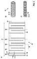
- Fig. 2 shows a first embodiment of a film 40, which represents a second component of an implantable medical device, and located in Fig. 2 a) in a unwound state and in Fig. 2 b) is in a wound over a mandrel 42 partially wound state.
- the film 40 in this embodiment has a plastic layer 44, for example made of or with a polymer such as polyester, polyimide, polyamide, polytetrafluoroethylene, polypropylene, polyurethane or the like and a metal layer 46 applied thereon, for example of gold or silver.
- the metal layer 46 may also be of another electrically conductive material, such as graphene or the like.
- the plastic layer 44 can also be made of a graphite composite or fluorograph.
- the metal layer 46 can also be connected to or embedded in the plastic layer 44, for example by gluing, pressing or the like.
- the film 40 has a length 47 of 500 mm and a width 49 of 181 mm.
- the film 40 can be used as a starting material for miniaturized implantable medical devices by moving the film 40 in the unwound state as in FIG Fig. 3 a) shown or in the wound state as in Fig. 3 b) or c) is shown, divided into sections 48.
- the division can be done physically, for example mechanically, thermally (ie under the effect of heat), for example by means of a laser or plasma nut or the like or chemically, for example by means of etching or the like. It is also possible chronologically successively or simultaneously to use a plurality of methods for dividing the film 40 into a plurality of sections 48. In this embodiment, the division takes place along a meandering arm 50, whereby shorter identical sections 48 are produced.
- the sections 48 may be hermetically connected by pressure, heat and / or solvent. Also, the metal layers 46 of the sections 48 can be electrically connected to each other and thus connected in series.
- the metal layer 46 may be applied to the plastic layer 44 in various forms.
- the metal layer 46 is applied meander-shaped, wherein the width of the meandering metal layer is 3 mm and this is surrounded by plastic layer-runners 44 with a width of 2 mm. Winding up the film 40 creates a spiral conduit in FIG Fig. 3 b) , By dividing, shorter spiral conduit sections 48 are formed Fig. 3c) ,
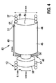
- Fig. 4 shows a first embodiment of a foil tape stop filter 52 as another embodiment of an implantable medical device.
- the foil tape stopper filter 52 includes an inner cylindrical platinum sleeve 54 electrically connected to the electrode wire 12 and around which the film 40 is spirally wound.
- the inner platinum sleeve 54 may be a part of a function conductor 30 or electrically connected to a function conductor 30 of the electrode line 12.
- a metal layer 46 of the foil 40 is electrically connected to the inner cylindrical platinum sleeve 54 and connected in series.
- the metal layers 46 act as inductors with helical winding in 76 windings with parasitic capacitances connected in parallel thereto. The number of windings depends on the thickness 51 (s. Fig. 5 ) of the film 40, can also be larger or be chosen smaller and is preferably adapted to the place of application of the implantable medical device.
- a second outer cylindrical platinum sleeve 56 with an inner diameter corresponding to the outer diameter of the wound film 40 encloses the wound film 40 in this exemplary embodiment.
- the outer cylindrical platinum sleeve 56 may be electrically connected to at least one metal layer 46 of the foil 40 and connected in series.
- a portion of the film 40 may also be passed outwardly around the outer platinum sleeve 56 through a slot in the outer platinum sleeve 56 (not shown).
- the inner platinum sleeve 54 may be slotted (not shown).
- the sleeves 54 and 56 can also be made of, for example, gold, silver, carbon nanotube composite, plastic or another conductive or non-conductive material, or contain such.
- the sleeves 54 or 56 may contain a conductive material, while the other sleeve 54 or 56 may be of a non-conductive material.
- the sleeves 54 or 56 may also be embodied as capillary tubes made of plastic, whereby a connection of the implantable medical devices is simplified when using the same material for the sleeves 54 and 56 as for the plastic layer 44.
- An electric wire in the form of a wire loop 57 encloses an inner insulating sheath 59 of the electrode line 12, which electrically insulates an inner electrical line connected to the inner platinum sleeve 54 from the wire helix 57.
- the inner electrical lead may also be a wire helix (not shown).
- the plastic layer 44 of the film 40 is in this embodiment of polyester and has a width 49 of 2 mm, a length 47 of 81 mm, and a thickness 51 of 1.2 microns or 1 micron (see Fig. 5 ).
- the metal layer 46 of the film 40 is arranged in this embodiment of gold and in the middle with a width 49 'of 1.8 mm, a length 47' of slightly less than 81 mm and a thickness 51 'of 0.300 microns on the plastic layer 44, so on the film 40, a non-conductive plastic edge 58 is generated (see FIG. 5 ).
- the width 49 'of the metal layer 46 is generally less than the width 49 of the film 40 or plastic layer 44.
- the metal layer 46 may also be incorporated within two plastic layers 44 in sandwich construction. Basically, the thickness 51 'of the metal layer 46 is less than its width 49' (see Fig. 5 ). In an alternative embodiment, the film 40 has a length of 14 cm (not shown).
- the inner platinum sleeve 54 is preferably slotted (not shown) and has an inner diameter of 0.4 mm, an outer diameter of 0.48 mm or 0.5 mm and a length of 2.5 mm.
- the length of the platinum sleeve 54 is thus 0.5 mm larger than the width 49 of the film 40, thus leaving a portion of the wrapped by the film 40 platinum sleeve 54 free and can be connected to the inner electrical line, such as a wire helix, an electrode.
- the platinum sleeve 54 can also be designed as an electrode itself.
- the metal layer 46 of the film 40 is contacted via a contact 60 (see FIG Fig. 5 ) is electrically connected to the inner platinum sleeve 54.
- the contact 60 in this embodiment has a width of 70 microns and is about 30 microns from the outer edge of the film 40 away.
- the slit of the inner platinum sleeve 54 prevents the short circuit of a winding, which would greatly reduce the inductance.
- the film 40 is enclosed in this embodiment by an outer platinum sleeve 56 having an inner diameter of 0.68 mm or 0.7 mm, an outer diameter of 0.8 mm and a length of 2.5 mm, wherein the film 40 is completely covered and 5 mm of the film 40 through a sleeve slot (not shown).
- the metal layer 46 of the film 40 is electrically connected to the outer shell of the outer platinum sleeve 56.
- a portion 61 of 0.5 mm of the outer platinum sleeve 56 extends beyond the width 49 of 2 mm of the film 40, whereby the outer platinum sleeve can be electrically connected to a continuing wire helix 57 under the sleeve.
- the slotted outer platinum sleeve 54 may taper to an outer diameter of 0.5 mm after a cylindrical portion of 2 mm enclosing the film 40 so that the wire helix 57 on the outside of the outer platinum sleeve 56 may be electrically connected.
- a smaller outer diameter of the implantable medical device may enable flexible contacting along the entire wire loop 57 without the need for further constructional changes to the electrodes 26 and 28, respectively.
- the foil tape stop filter 52 or the implantable medical device is preferably arranged at the distal end 24 or near the distal end 24 of the electrode 26 in order to reduce the heating of the electrode 26 and of the tissue surrounding the electrode 26 in a particularly effective manner.
- an implantable medical device in the immediate vicinity of the ring electrode 28, preferably immediately distal to the ring electrode 28, an implantable medical device can be arranged, whereby an additional mechanical protection can be achieved.
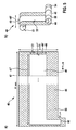
- Fig. 5 a shows a second embodiment of a film 40 having a center along the length 47 of the film 40 extending metal layer 46 having a length 47 ', which is applied to a plastic layer 44.
- the metal layer 46 may be electrically connected to the inner platinum sleeve 54 via the contact 60.
- Fig. 5b) the film 40 is partially wound on an inner platinum sleeve 54 and electrically connected thereto.
- the metal layer 46 on the foil 40 has two non-conductive plastic edges 58 along the longitudinal axis direction of the platinum sleeve 54.
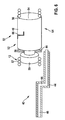
- Fig. 6 shows the second embodiment of a film 40 in a second embodiment of a film tape stopper filter 52.
- two spirally wound films 40 enclose an inner platinum sleeve 54 and are themselves enclosed by an outer platinum sleeve 56.
- a proximal foil 62 is electrically connected to the outer wall of the inner platinum sleeve 54.
- a second, distal foil 64 is electrically connected at its proximal end to the proximal foil 62 and at its distal end to the outer platinum sleeve 56, whereby a series connection of the platinum sleeves 54 and 56 is realized with the films 62 and 64.
- the serial interconnection of several foils 40 which serve as filters, makes it possible to achieve a desired frequency response.
- the series connection is realized by step-cut films 40, wherein after each wound film 40, an electrically conductive web 66 is returned from the metal layer 46 of the film 62 in the vicinity of the outer wall of the inner platinum sleeve 54 to electrically connect it to a metal layer 46 of the axially adjacent foil 64.
- the film 64 following the first film 62 is not electrically connected to the inner platinum sleeve 54, since this would lead to a parallel connection.
- Cylindrical surfaces of the axially adjacent films 62 and 64 may be hermetically joined together by pressure, heat and / or solvent to hermetically seal the film belt stop filter 52.
- the distal foil 64 may also be electrically connected to the inner platinum sleeve 54, whereby the bandwidth of the implantable medical device may be adjusted.
- both bandwidth and transmission frequencies can be set so that a cooling effect can also occur in a plurality of frequency bands and the manufacturing tolerance can be increased.
- Fig. 7 shows the second embodiment of the film 40 in a third embodiment of a film tape stopper filter 52.
- the film tape stopper filter 52 in this embodiment is substantially identical to the film tape stopper filter 52 of the second embodiment in FIG Fig. 6 but includes three instead of two series-connected foil sections.
- the exact geometrical dimensions of the flexible film belt stop filter 52 depend on the external restrictions of the place of use (maximum outer diameter r 2 , minimum inner diameter r 1 and maximum length b), the choice of material of the plastic layer 44 or of the film substrate and the shape and material of the metal layer 46 or metallization and the desired resonance frequency.
- a foil tape stopper filter 52 similar to that in FIG Fig. 7 shown adopted, but from sections 48 of the film 40 from Fig. 2 respectively.
- Fig. 3 is constructed, which have a meandering metal layer 46.
- a further embodiment is optimized for installation in a pacemaker electrode for frequencies around 64 MHz and comprises the following parameters:
Landscapes
- Health & Medical Sciences (AREA)
- Heart & Thoracic Surgery (AREA)
- Life Sciences & Earth Sciences (AREA)
- Cardiology (AREA)
- Animal Behavior & Ethology (AREA)
- Veterinary Medicine (AREA)
- Radiology & Medical Imaging (AREA)
- Biomedical Technology (AREA)
- Engineering & Computer Science (AREA)
- General Health & Medical Sciences (AREA)
- Public Health (AREA)
- Nuclear Medicine, Radiotherapy & Molecular Imaging (AREA)
- Physics & Mathematics (AREA)
- Electromagnetism (AREA)
- Vascular Medicine (AREA)
- Biophysics (AREA)
- Physiology (AREA)
- Electrotherapy Devices (AREA)
Abstract
Description
- Die Erfindung betrifft ein permanent oder temporär implantierbares medizinisches Gerät mit einem langgestreckten elektrischen Leiter und ein Herstellungsverfahren für ein implantierbares medizinisches Gerät.
- Elektrische Leiter enthaltende medizinische Geräte, beispielsweise Elektrodenleitungen für Elektrostimulation oder Elektroden für Herzschrittmacher, haben den Nachteil, dass sich der elektrische Leiter in einem elektromagnetischen Wechselfeld, zum Beispiel in einem Kernspintomografen, erwärmen kann, weil elektromagnetische Wechselfelder in dem elektrischen Leiter elektrische Ströme induzieren. Die Erwärmung tritt vorzugsweise an Leitungsenden auf und ist abhängig von der Amplitude der Wellen des elektromagnetischen Wechselfeldes, wobei die Erwärmung maximal bei Ausbildung stehender Wellen ist.
- Implantierbare Herzschrittmacher oder Defibrillatoren sind typischerweise mit wenigstens einer Stimulationselektrodenleitung verbunden. Der Herzschrittmacher oder Defibrillator enthält an seinem distalen Ende, das vorgesehen ist im Herzen platziert zu werden, einen oder mehrere Elektrodenpole. Solche Elektrodenpole dienen zur Abgabe elektrischer Impulse, beispielsweise an das Gewebe (Myokard) des Herzens oder zum Abfühlen elektrischer Felder, um im Rahmen des sogenannten Sensings eine Aktivität, beispielsweise eine Herzaktivität abfühlen zu können.
- Zu diesem Zweck bilden Elektrodenpole typischerweise elektrisch leitende Oberflächenabschnitte einer Elektrodenleitung. Typischerweise sind die Elektrodenpole als Ringelektroden in Form eines Rings um die Elektrodenleitung oder in Form einer Spitzen- oder Tipelektrode am distalen Ende der Elektrodenleitung vorgesehen. Die Elektrodenpole sind über einen oder mehrere elektrische Leiter mit Kontakten eines elektrischen Anschlusses der Elektrodenleitung an deren proximalen Enden elektrisch leitend verbunden. Die elektrischen Leiter können zur Übertragung von Stimulationsimpulsen zu den Elektrodenpolen und/oder zur Übertragung von, von den Elektrodenpolen aufgenommenen, elektrischen Signalen zum proximalen Ende der Elektrodenleitung, genutzt werden. Elektrische Leiter die dem Einsatzzweck der Elektrodenleitung (d.h. der Primär-Funktion der Elektrodenleitung) dienen, werden im Rahmen dieses Textes als Funktionsleiter bezeichnet.
- Durch äußere Wechselmagnetfelder können in den Funktionsleitern elektrische Ströme induziert werden, die beispielsweise zu einer Erwärmung der Funktionsleiter und/oder der mit ihnen verbundenen Elektrodenpole führen kann. Falls die Funktionsleiter mit Elektrodenpolen verbunden sind, die im Betrieb Kontakt mit umgebendem Gewebe haben, kann die Induktion von Strömen in einem Funktionsleiter zu einer Erwärmung von an den Funktionsleiter angeschlossenen Elektrodenpolen und zu einer Erwärmung des umgebenden Gewebes führen.
-
US 7,904,178 B2 zeigt einen langgestreckten Körper einer medizinischen, elektrischen Leitung mit wenigstens einem in eine Spule geformten Leiter. Der Leiter enthält einen ersten sich innerhalb einer Isolationsaußenhülle erstreckenden Abschnitt und einen zweiten Abschnitt der sich außerhalb der Isolationsaußenhülle erstreckt und als Energieabführender Shunt verwendet wird. -
US 6,871,091 B2 offenbart eine elektrische Leitung mit einem langgestreckten Körper. Die elektrische Leitung umfasst distale und proximale Endabschnitte, eine erste mit dem distalen Endabschnitt des langgestreckten Körpers verbundene Elektrode und einen ersten sich zwischen distalem und proximalem Endabschnitt erstreckenden Leiter, der elektrisch mit der ersten Elektrode verbunden ist. Eine zweite Elektrode ist mit dem langgestreckten Körper verbunden und ein Kondensator ist elektrisch mit dem ersten Leiter und der zweiten Elektrode verbunden. - Der Erfindung liegt die Aufgabe zugrunde, eine mögliche Erwärmung der Elektrodenleitung und/oder des mit der Elektrodenleitung in Kontakt befindlichen Gewebes zu verringern. Ein weiterer Aspekt betrifft ein Verfahren, welches die sichere und kostengünstige Herstellung eines miniaturisierten implantierbaren medizinischen Geräts ermöglicht, das eine verringerte Erwärmung der Elektrodenleitung und/oder des mit der Elektrodenleitung in Kontakt befindlichen Gewebes und eine erhöhte mechanische und elektrische Stabilität aufweist, sowie durch eine hermetische Bauweise bei geringem Einsatz verschiedener Stoffgruppen ausgezeichnet ist.
- Erfindungsgemäß wird dies erreicht durch ein temporär oder permanent implantierbares medizinisches Gerät mit wenigstens einer langgestreckten elektrischen Leitung, die einen Funktionsleiter als erste elektrische Komponente oder als Teil einer ersten elektrischen Komponente enthält. Die erste elektrische Komponente des medizinischen Geräts hat wenigstens zu einer zweiten Komponente elektrischen Kontakt, die einen Verbund aus wenigstens einer Metallschicht und wenigstens einer biegeschlaffen Kunststoffschicht aufweist. Dabei ist wenigstens eine der Metallschichten der zweiten Komponente in Serie mit der ersten elektrischen Komponente geschaltet.
- Durch eine mit einer Elektrode bzw. der ersten Komponente in Serie geschaltete Metallschicht der zweiten Komponente werden elektromagnetische Wellen im Radiofrequenzbereich zurückreflektiert und somit die Erwärmung des Gewebes insbesondere am oder nahe dem distalen Ende des medizinischen Geräts verringert. Die Einfache und kompakte Bauweise des medizinischen Geräts erzeugt eine hohe mechanische Stabilität, insbesondere in Zugrichtung und vereinfacht die elektrische Kontaktierung zu einer Drahthelix bzw. Innenwendel einer Elektrode. Die Verwendung einer Kunststoffschicht ermöglicht ein hermetisches Versiegeln der leitenden Teile des implantierbaren medizinischen Geräts, wodurch Einflüsse durch elektrolytische Flüssigkeiten nahezu ausgeschlossen werden können und wodurch die Auswahl für die verwendbaren Elemente der Metallschicht erweitert werden kann.
- Ein Herstellungsverfahren für das implantierbare medizinische Gerät umfasst, Bereitstellen einer elektrischen Leitung und wenigstens einer zweiten Komponente mit wenigstens einer Metallschicht. Die elektrische Leitung enthält einen Funktionsleiter als erste elektrische Komponente oder als Teil einer ersten elektrischen Komponente. Die Metallschicht der zweiten Komponente wird mit einer biegeschlaffen Kunststoffschicht verbunden. Indem die wenigstens eine Metallschicht der zweiten mit der ersten elektrischen Komponente verbunden wird, wird eine Serienschaltung der ersten mit der zweiten Komponente erzeugt. Bevorzugt werden mehrere zweite Komponenten in Serienschaltung verschaltet.
- Durch das Herstellungsverfahren kann ein miniaturisiertes implantierbares medizinisches Gerät hergestellt werden, wobei durch die mit der ersten Komponente in Serie geschaltete Metallschicht der zweiten Komponente elektromagnetische Wellen im Radiofrequenzbereich zurückreflektiert werden und somit die Erwärmung des Gewebes insbesondere am oder nahe dem distalen Ende des medizinischen Geräts verringert wird. Das Herstellungsverfahren erlaubt des Weiteren eine gute Automatisierung bei geringer Anfälligkeit gegenüber von Produktionsintoleranzen, wodurch eine kostengünstige und flexible Serienproduktion ermöglicht werden kann. Das Herstellungsverfahren schließt auch eine sichere elektrische Kontaktierung der Komponenten ein. Dies ist auch bei großer Dimensionierung (> 10 mm) möglich, wobei die implantierbaren medizinischen Geräte durch Teilung miniaturisiert werden können.
- In einer bevorzugten Ausgestaltung ist das implantierbare medizinische Gerät eine Elektrodenleitung oder ein Teil einer Elektrodenleitung. Die Elektrodenleitung kann über einen Anschluss mit einem Therapie- oder Monitoringgerät verbunden werden. Das implantierbare medizinische Gerät kann auch ein Teil eines Therapie- oder Monitoringgeräts sein.
- In einer besonders bevorzugten Ausgestaltung ist die Breite der Metallschicht der zweiten Komponente geringer als die Breite der Kunststoffschicht, wodurch die zweite Komponente einen elektrisch nichtleitenden Kunststoffrand aufweist. Der Rand kann auf einer oder bevorzugt auf beiden Seiten der zweiten Komponente vorhanden sein. In einer weiteren Ausgestaltung kann der Kunststoffrand einen anderen Kunststoff als die Kunststoffschicht enthalten oder auf die Kunststoffschicht aufgetragen sein. Die Metallschicht der zweiten Komponente kann auch von einer oder mehreren Kunststoffschichten umschlossen sein, beispielsweise in Sandwichbauweise oder dergleichen. Alternativ ist die Metallschicht in eine Kunststoffschicht eingebettet oder auf mehrere Kunststoffschichten aufgetragen. Bevorzugt ist der Kunststoff ein biegeschlaffer Kunststoff, der sich in, beispielsweise eine Zylinderform oder um einen Zylinder wickeln lässt, ohne dass die zweite Komponente verletzt wird. Die biegeschlaffe Kunststoffschicht der zweiten Komponente kann ein oder mehr Polymere, beispielsweise Polyester, Polyimid, Polyamid, Polytetrafluorethylen, Polypropylen, Polyurethan oder dergleichen enthalten.
- Die Metallschicht kann derart ausgebildet sein, dass ein Wickeln in beispielsweise Zylinderform die elektrische Leitung entlang der Metallschicht nicht unterbricht. Die Metallschicht kann ein oder mehrere Metalle, beispielsweise Gold, Silber oder dergleichen enthalten.
- In einer weiteren Ausgestaltung ist die Metallschicht der zweiten Komponente mäanderförmig auf die biegeschlaffe Kunststoffschicht aufgetragen. Auch kann die Auftragung der Metallschicht in verschiedenen anderen Formen, beispielsweise zickzackförmig, spiralförmig, labyrinthförmig oder dergleichen erfolgen. Besonders bevorzugt ist die Auftragung der Metallschicht in einer Form, die bei einer Zerteilung der zweiten Komponente entlang einer Achse senkrecht zur Längsachse der flachen zweiten Komponente gleiche, elektrisch entlang einer durchgängigen Metallschicht leitende Teilabschnitte erzeugt, beispielsweise Metallschichtauftragungen mit Mäanderform, Zickzackform oder dergleichen.
- Die zweite Komponente kann in zwei oder mehr Teilabschnitte, beispielsweise entlang eines bzw. mehrerer Mäanderarme, bevorzugt an jeweils jedem zweiten Mäanderarm, zerteilt werden. Die Zerteilung der zweiten Komponente kann dabei physikalisch, beispielweise mechanisch, thermisch (d. h. unter Hitzeeinwirkung), wie beispielsweise mittels Laser oder Plasmakauter oder dergleichen und/oder chemisch, beispielsweise mittels Ätzung oder dergleichen erfolgen. Bevorzugt werden die durch die Trennung entstandenen Zylinderflächen der Teilabschnitte durch Druck, Wärme und/oder Lösungsmittel miteinander hermetisch verbunden. Besonders bevorzugt werden dabei die Metallschichten zueinander benachbart angeordneter zweiter Komponenten derart elektrisch miteinander verbunden, dass eine Serienschaltung erzeugt wird.
- Die zweite Komponente ist bevorzugt spiralförmig um eine Längsachse aufgewickelt. Es können auch mehrere zweite Komponenten axial entlang einer Längsachse angeordnet um die Längsachse oder koaxial umeinander aufgewickelt sein. Bevorzugt ist die jeweilige wenigstens eine Metallschicht der aufgewickelten zweiten Komponenten elektrisch in der Art mit wenigstens einer Metallschicht einer anderen zweiten Komponente verbunden, so dass eine Serienschaltung erzeugt wird. Die Anzahl der Wicklungen liegt bevorzugt zwischen 50 und 100, besonders bevorzugt zwischen 74 und 76, kann aber auch in Abhängigkeit der Dicke und Länge der zweiten Komponente größer oder kleiner sein. In Abhängigkeit der Form und Wicklung der in den zweiten Komponenten enthaltenen Metall- und Kunststoffschicht können Induktivitäten und dazu parallel geschaltete parasitäre Kapazitäten justiert werden, wodurch ein implantierbares medizinisches Gerät mit Impedanzen von >1 kOhm bei elektrischen Wellen im Radiofrequenzbereich erzeugt werden kann, dass eine geringe Güte auf Grund der Nutzung parasitärer Kapazitäten aufweist, so dass das implantierbare medizinische Gerät über die maximale Impedanz im Resonanzfall hinaus eine signifikant erhöhte Impedanz aufweist und somit breitbandig wirken kann.
- Die Längsachse, um die die zweiten Komponenten aufgewickelt werden können, kann zum Beispiel einen Zylinder, einen Dorn, einen Schlauch, ein Kapillarrohr aus Kunststoff oder dergleichen enhalten. Durch das Umwickeln der Längsachse kann eine spiralförmige Leitung bzw. können hohle spiralförmige Leitungsabschnitte erzeugt werden. Die zweite Komponente kann auch die erste Komponente umschließen. Bevorzugt ist die erste Komponente in diesem Fall eine Metallhülse, besonders bevorzugt eine geschlitzte Platinhülse. Eine dritte Komponente, beispielsweise eine weitere Metallhülse, kann die zweite Komponente teilweise oder vollständig umschließen. Auch kann ein Teil der zweiten Komponente aus der dritten Komponente herausragen, falls diese nicht vollständig umschlossen ist. In einer Ausgestaltung ist die dritte Komponente eine geschlitzte Platinhülse mit einem größeren Innendurchmesser als der Außendurchmesser der aufgewickelten zweiten Komponente. Die zweite Komponente kann mit einem Teil aufgewickelt von der Platinhülse umschlossen sein, während ein anderer Teil der zweiten Komponente aus dem Schlitz der Platinhülse herausragt. Die Platinhülse kann eine Elektrode bzw. ein Elektrodenpol zur Abgabe von Stimulationsimpulsen oder zum Erfassen von elektrischen Potentialen sein und mit einer Metallschicht der zweiten Komponente elektrischen Kontakt haben bzw. in Serie verschaltet sein.
- Die Dicke der Metallschicht ist bevorzugt geringer als die Breite der Metallschicht, beispielsweise mit einer Dicke zwischen 0,045 µm und 0,300 µm und einer Breite von 1,8 mm.
- Das Verfahren zur Herstellung eines implantierbaren medizinischen Geräts umfasst bevorzugt einen Schritt, bei dem die Ränder der Kunststoffschicht der zweiten Komponente durch Druck, Wärme und/oder Lösungsmittel miteinander hermetisch verbunden werden.
- Des Weiteren kann das Verfahren einen Schritt umfassen, bei dem wenigstens ein Abschnitt der zweiten Komponente physikalisch in axial angeordnete Teilabschnitte zerteilt wird. Die zweite Komponente kann auch chemisch zerteilt werden. Auch können physikalische und chemische Methoden für die Zerteilung gleichzeitig nebeneinander oder chronologisch nacheinander ausgeführt werden, um die Trennung der Abschnitte der zweiten Komponente zu bewirken.
- Bevorzugt enthält das Verfahren einen Schritt zum Verbinden von axial angeordneten Teilabschnitten der zweiten Komponente. Die axial angeordneten Teilabschnitte können durch Druck, Wärme und/oder Lösungsmittel miteinander hermetisch verbunden werden. Bevorzugt werden die Metallschichten der axial angeordneten Teilabschnitte derart miteinander verbunden, dass eine Serienschaltung erzeugt wird.
- Das implantierbare medizinische Gerät kann eine proximale und eine distale Seite haben. Auch die im implantierbaren medizinischen Gerät enthaltenen Komponenten können proximale und distale Seiten aufweisen. Die distale Seite der ersten elektrischen Komponente hat bevorzugt Kontakt zu einem biologischen Körper, beispielsweise Gewebe, Blut oder dergleichen. Die erste elektrische Komponente kann in diesem Fall Stimulationsimpulse an den biologischen Körper übertragen oder elektrische Signale aus dem Gewebe durch einen am oder nahe dem Ende der ersten Komponente angeordneten Sensor empfangen, um diese elektrischen Signale an das proximale Ende der ersten Komponente zu übertragen. Die Signale können dort von einer Verarbeitungseinheit analysiert bzw. verarbeitet werden, um beispielsweise die Stimulationspulse neu zu justieren.
- Die Erfindung soll nun anhand von in den Figuren schematisch abgebildeten Ausführungsbeispielen näher erläutert werden. Von den Figuren zeigen:
- Fig. 1
- eine schematische Darstellung eines implantierbaren Herzstimulators und eine an diesen angeschlossene implantierbare Elektrodenleitung.
- Fig. 2
- eine schematische Darstellung eines ersten Ausführungsbeispiels einer Folie eines implantierbaren medizinischen Geräts im unaufgewickelten und im über einen Dorn teilaufgewickelten Zustand.
- Fig. 3
- eine schematische Darstellung des ersten Ausführungsbeispiels einer Folie eines implantierbaren medizinischen Geräts mit mehr Details.
- Fig. 4
- eine schematische Darstellung eines ersten Ausführungsbeispiels eines Folienbandstoppfilters.
- Fig. 5
- eine schematische Darstellung eines zweiten Ausführungsbeispiels einer Folie eines implantierbaren medizinischen Geräts im unaufgewickelten und im über eine Platinhülse teilaufgewickelten Zustand.
- Fig. 6
- eine schematische Darstellung des zweiten Ausführungsbeispiels einer Folie eines implantierbaren medizinischen Geräts in einem zweiten Ausführungsbeispiel eines Folienbandstoppfilters.
- Fig. 7
- eine schematische Darstellung des zweiten Ausführungsbeispiels einer Folie eines implantierbaren medizinischen Geräts in einem dritten Ausführungsbeispiel eines Folienbandstoppfilters.
-
Fig. 1 zeigt als Beispiele implantierbarer medizinischer Geräte einen implantierbaren Herzstimulator 10 und eine mit diesem elektrisch verbundene implantierbare Elektrodenleitung 12. - Der implantierbare Herzstimulator 10 ist im dargestellten Ausführungsbeispiel ein ventrikulärer Herzschrittmacher und Defibrillator, kann aber auch ein Herzschrittmacher, ein Kardioverter/Defibrillator (ICD), ein reines Monitoringgerät zur Herzüberwachung, eine Kombination aus Therapie- und Monitoringgerät, eine Ablationselektrodenleitung oder dergleichen sein.
- Der Herzstimulator besitzt ein elektrisch leitendes Metallgehäuse 14, das als großflächiger Elektrodenpol dienen kann. Alternativ kann das Gehäuse 14 auch aus einem anderen, insbesondere nichtleitenden, Material sein. Das Gehäuse 14 hat an seiner Außenseite 16 ein Anschlussgehäuse 18, das auch als Header bezeichnet wird. Das Anschlussgehäuse 18 enthält Kontaktbuchsen 20 mit elektrischen Kontakte 22 zur Aufnahme von Steckkontakten. Die elektrischen Kontakte 22 sind mit Leitern mit einer im Gehäuse 14 des Herzstimulators 10 angeordneten Elektronik verbunden.
- Im Folgenden betrachten wir die Elektrodenleitung 12, die ein weiteres implantierbares medizinisches Gerät im Sinne der Erfindung darstellt. Das distale Ende 24 der Elektrodenleitung 12 befindet sich im Apex eines rechten Ventrikels eines Herzens und enthält Elektrodenpole 26 bzw. 28 in Form einer Spitzen- oder Tip-Elektrode 26 und einer in deren Nähe angeordneten Ringelektrode 28. Die Elektrodenpole 26 und 28 sind über einen oder mehrere elektrische Funktionsleiter 30 mit jeweils einem Steckkontakt 32 am proximalen Ende 34 der Elektrodenleitung 12 elektrisch verbunden und können zum Abfühlen elektrischer Potenziale des Herzgewebes (Myokards) oder zur Abgabe elektrische Signale, z. B. in Form von Stimulationspulsen an das sie umgebende Herzgewebe, dienen. Die Funktionsleiter 30 können beispielsweise der Therapie dienende elektrische Signale von dem Steckkontakt 32 zum jeweiligen Elektrodenpol 26 bzw. 28 übertragen oder abgefühlte elektrische Potentiale repräsentierende Signale vom jeweiligen Elektrodenpol 26 bzw. 28 zum Steckkontakt 32 führen und somit der elementaren Funktion der medizinischen Geräte dienen. Die Funktionsleiter 30 sind über einen Großteil ihrer Länge von einer isolierenden Hülle umgeben, so dass ein elektrischer Kontakt zum Gewebe des Herzens gezielt über die Elektrodenpole 26 bzw. 28 zustande kommt. Der Steckkontakt 32 ist mit seinen elektrischen Kontakten mit den elektrischen Kontakten 22 der Kontaktbuchse 20 im Anschlussgehäuse 18 des implantierbaren Herzstimulators 10 verbunden, wodurch Signale von bzw. zu der im Gehäuse 14 des Herzschrittmachers 10 gelegenen Elektronik an die bzw. von den Elektrodenpole(n) 26 bzw. 28 übertragen werden können. Die Elektrodenleitung 12 kann auch Teil der Herzschrittmachers 10 bzw. mit diesem fest verbunden sein.
- Die elektrischen Funktionsleiter 30 in der Elektrodenleitung 12 können in unterschiedlichen Längsabschnitten als annähernd gestreckte Seilzugleiter oder als helixförmig gewendelte Leiter bzw. Drahthelices ausgebildet sein. Die Elektrodenleitung 12 im dargestellten Ausführungsbeispiel enthält zusätzlich einen großflächigen proximalen Elektrodenpol 36 und einen großflächigen distalen Elektrodenpol 38, die jeweils von wenigstens einem blank liegenden helixförmig gewendelten Draht gebildet werden und als Defibrillationselektroden 36 und 38 dienen. Die Elektrodenleitung 12 kann auch für die Stimulation und Ableitung von Signalen an Nerven, Gehirn, und anderen Organen oder für die Zuleitung von implantierbaren Sensoren Verwendung finden.
-
Fig. 2 zeigt ein erstes Ausführungsbeispiel einer Folie 40, die eine zweite Komponente eines implantierbaren medizinischen Geräts darstellt, und die sich inFig. 2 a) in einem unaufgewickelten Zustand und inFig. 2 b) in einem über eine Dorn 42 teilaufgewickelten Zustand befindet. Die Folie 40 hat in diesem Ausführungsbeispiel eine Kunststoffschicht 44, beispielsweise aus oder mit einem Polymer wie Polyester, Polyimid, Polyamid, Polytetrafluorethylen, Polypropylen, Polyurethan oder dergleichen und eine auf diese aufgetragene Metallschicht 46, beispielsweise aus Gold oder Silber. Die Metallschicht 46 kann auch aus einem anderen elektrisch leitenden Material sein, beispielsweise Graphen oder dergleichen. Die Kunststoffschicht 44 kann auch aus einem Graphenkomposit oder Fluorographen sein. Die Metallschicht 46 kann auch mit der Kunststoffschicht 44, beispielsweise über Kleben, Pressen oder dergleichen verbunden oder in diese eingebettet sein. In diesem Ausführungsbeispiel hat die Folie 40 eine Länge 47 von 500 mm und eine Breite 49 von 181 mm. - Die Folie 40 kann als Ausgangsmaterial für miniaturisierte implantierbare medizinische Geräte verwendet werden, indem die Folie 40 im unaufgewickelten Zustand wie in
Fig. 3 a) gezeigt oder im aufgewickelten Zustand wie inFig. 3 b) bzw. c) gezeigt, in Teilabschnitte 48 zerteilt wird. Die Zerteilung kann physikalisch, beispielweise mechanisch, thermisch (d. h. unter Hitzeeinwirkung), wie beispielsweise mittels Laser oder Plasmakauter oder dergleichen oder chemisch, beispielsweise mittels Ätzung oder dergleichen erfolgen. Es können auch chronologisch nacheinander oder gleichzeitig mehrere Verfahren zur Zerteilung der Folie 40 in mehrere Teilabschnitte 48 verwendet werden. In diesem Ausführungsbeispiel erfolgt die Zerteilung entlang eines Mäanderarms 50, wodurch kürzere identische Teilabschnitte 48 erzeugt werden. Die Teilabschnitte 48 können durch Druck, Wärme und/oder Lösungsmittel hermetisch miteinander verbunden werden. Auch die Metallschichten 46 der Teilabschnitte 48 können miteinander elektrisch verbunden und somit in Serie geschaltet werden. - Die Metallschicht 46 kann in verschiedenen Formen auf die Kunststoffschicht 44 aufgetragen werden. In diesem Ausführungsbeispiel ist die Metallschicht 46 mäanderförmig aufgetragen, wobei die Breite der mäanderförmigen Metallschicht 3 mm beträgt und diese von Kunststoffschicht-Läufern 44 mit einer Breite von 2 mm umgeben ist. Aufwickeln der Folie 40 erzeugt eine spiralförmige Leitung in
Fig. 3 b) . Durch Zerteilen, entstehen kürzere spiralförmige Leitungsabschnitte 48 inFig. 3 c) . -
Fig. 4 zeigt ein erstes Ausführungsbeispiel eines Folienbandstoppfilters 52 als weiteres Ausführungsbeispiel für ein implantierbares medizinisches Gerät. Der Folienbandstoppfilter 52 enthält eine innere zylinderförmige mit der Elektrodenleitung 12 elektrisch verbundene Platinhülse 54 um die die Folie 40 spiralförmig aufgewickelt ist. Die innere Platinhülse 54 kann dabei ein Teil eines Funktionsleiters 30 oder mit einem Funktionsleiter 30 der Elektrodenleitung 12 elektrisch verbunden sein. Eine Metallschicht 46 der Folie 40 ist mit der inneren zylinderförmigen Platinhülse 54 elektrisch verbunden und in Serie verschaltet. Die Metallschichten 46 wirken durch das spiralförmige Aufwickeln in 76 Wicklungen als Induktivitäten mit dazu parallel geschalteten parasitären Kapazitäten. Die Anzahl der Wicklungen hängt von der Dicke 51 (s.Fig. 5 ) der Folie 40 ab, kann auch größer oder kleiner gewählt werden und ist bevorzugt auf den Anwendungsort des implantierbaren medizinischen Geräts angepasst. - Eine zweite äußere zylinderförmige Platinhülse 56 mit einem zum Außendurchmesser der aufgewickelten Folie 40 korrespondierenden Innendurchmesser umschließt die aufgewickelte Folie 40 in diesem Ausführungsbeispiel. Die äußere zylinderförmige Platinhülse 56 kann mit wenigstens einer Metallschicht 46 der Folie 40 elektrisch verbunden und in Serie verschaltet sein. Ein Teil der Folie 40 kann auch durch einen Schlitz in der äußeren Platinhülse 56 nach Außen um die äußere Platinhülse 56 geführt sein (nicht gezeigt). Auch die innere Platinhülse 54 kann geschlitzt sein (nicht gezeigt). Die Hülsen 54 bzw. 56 können auch aus beispielsweise Gold, Silber, Kohlenstoffnanoröhrenkomposit, Kunststoff oder einem anderen leitenden oder nichtleitenden Material sein, bzw. ein solches enthalten. Auch kann nur eine der Hülsen 54 oder 56 ein leitendes Material enthalten, während die andere Hülse 54 oder 56 aus einem nichtleitenden Material sein kann. Die Hülsen 54 oder 56 können auch als Kapillarrohre aus Kunststoff ausgeführt sein, wodurch bei Verwendung des gleichen Materials für die Hülsen 54 und 56 wie für die Kunststoffschicht 44 eine Verbindung der implantierbaren medizinischen Geräte vereinfacht wird. Insbesondere die Verwendung des gleichen Materials für die innere zylinderförmige Hülse 54 und die Kunststoffschicht 44 vereinfacht die mechanische Verbindung der implantierbaren medizinischen Geräte.
- Eine elektrische Leitung in Form einer Drahthelix 57 umschließt eine innere Isolationshülle 59 der Elektrodenleitung 12, die eine mit der inneren Platinhülse 54 verbundene innere elektrische Leitung elektrisch von der Drahthelix 57 isoliert. Die innere elektrische Leitung kann auch eine Drahthelix sein (nicht gezeigt).
- Die Kunststoffschicht 44 der Folie 40 ist in diesem Ausführungsbeispiel aus Polyester und hat eine Breite 49 von 2 mm, eine Länge 47 von 81 mm, sowie eine Dicke 51 von 1,2 µm oder 1 µm (siehe
Fig. 5 ). Die Metallschicht 46 der Folie 40 ist in diesem Ausführungsbeispiel aus Gold und mittig mit einer Breite 49' von 1,8 mm, einer Länge 47' von etwas weniger als 81 mm und einer Dicke 51' von 0,300 µm auf der Kunststoffschicht 44 angeordnet, sodass auf der Folie 40 ein nichtleitender Kunststoffrand 58 erzeugt wird (sieheFig. 5 ). Die Breite 49' der Metallschicht 46 ist grundsätzlich geringer als die Breite 49 der Folie 40 bzw. Kunststoffschicht 44. Alternativ kann die Metallschicht 46 auch innerhalb von zwei Kunststoffschichten 44 in Sandwichbauweise eingebracht sein. Grundsätzlich ist die Dicke 51' der Metallschicht 46 geringer als ihre Breite 49' (sieheFig. 5 ). In einem alternativen Ausführungsbeispiel hat die Folie 40 eine Länge von 14 cm (nicht gezeigt). - Die innere Platinhülse 54 ist bevorzugt geschlitzt (nicht gezeigt) und hat einen Innendurchmesser von 0,4 mm, einen Außendurchmesser von 0,48 mm oder 0,5 mm und eine Länge von 2,5 mm. Die Länge der Platinhülse 54 ist somit 0,5 mm größer als die Breite 49 der Folie 40, somit bleibt ein Teil der von der Folie 40 umwickelten Platinhülse 54 frei und kann mit der inneren elektrischen Leitung, beispielsweise einer Drahthelix, einer Elektrode verbunden werden. Die Platinhülse 54 kann auch selbst als Elektrode ausgeführt sein. Die Metallschicht 46 der Folie 40 ist über einen Kontakt 60 (siehe
Fig. 5 ) elektrisch mit der inneren Platinhülse 54 verbunden. Der Kontakt 60 hat in diesem Ausführungsbeispiel eine Breite von 70 µm und ist vom Außenrand der Folie 40 ca. 30 µm entfernt. Die Schlitzung der inneren Platinhülse 54 verhindert den Kurzschluss einer Wicklung, der die Induktivität stark herabsetzen würde. - Senkrechtes Abwickeln zur Breite 49 der Folie 40 um die Platinhülse 54 erzeugt einen Außendurchmesser der aufgewickelten Folie 40 von 0,7 mm. Die Folie 40 ist in diesem Ausführungsbeispiel von einer äußeren Platinhülse 56 mit einem Innendurchmesser von 0,68 mm oder 0,7 mm, einem Außendurchmesser von 0,8 mm und einer Länge von 2,5 mm umschlossen, wobei die Folie 40 vollständig bedeckt wird und 5 mm der Folie 40 durch einen Hülsenschlitz (nicht gezeigt) geführt werden. Die Metallschicht 46 der Folie 40 ist mit der Außenhülle der äußeren Platinhülse 56 elektrisch verbunden. Ein Anteil 61 von 0,5 mm der äußeren Platinhülse 56 reicht über die Breite 49 von 2 mm der Folie 40 hinaus, wodurch die äußere Platinhülse mit einer weiterführenden Drahthelix 57 unter der Hülse elektrisch verbunden werden kann. Alternativ kann sich die geschlitzte äußere Platinhülse 54 nach einem zylindrischen Abschnitt von 2 mm, der die Folie 40 umschließt auf einen Außendurchmesser von 0,5 mm verjüngen, so dass die Drahthelix 57 auf der Außenseite der äußeren Platinhülse 56 elektrisch verbunden werden kann.
- Ein geringerer Außendurchmesser des implantierbaren medizinischen Geräts kann eine flexible Kontaktierung entlang der gesamten Drahthelix 57 ermöglichen ohne dass weitere bauliche Veränderungen der Elektrode 26 bzw. 28 notwendig sind.
- Bevorzugt ist der Folienbandstoppfilter 52 bzw. das implantierbare medizinische Gerät am distalen Ende 24 oder nahe dem distalen Ende 24 der Elektrode 26 angeordnet, um die Erwärmung der Elektrode 26 und des die Elektrode 26 umgebenden Gewebes besonders effektiv zu vermindern. Alternativ oder zusätzlich kann in unmittelbarer Nähe zur Ringelektrode 28, bevorzugt unmittelbar distal zur Ringelektrode 28 ein implantierbares medizinisches Gerät angeordnet sein, wodurch ein zusätzlicher mechanischer Schutz erreicht werden kann.
-
Fig. 5 a) zeigt ein zweites Ausführungsbeispiel einer Folie 40 mit einer mittig entlang der Länge 47 der Folie 40 verlaufenden Metallschicht 46 mit einer Länge 47', die auf eine Kunststoffschicht 44 aufgetragen ist. Die Metallschicht 46 kann über den Kontakt 60 mit der inneren Platinhülse 54 elektrisch verbunden werden. InFig. 5 b) ist die Folie 40 auf eine innere Platinhülse 54 teilaufgewickelt und mit dieser elektrisch verbunden. Die Metallschicht 46 auf der Folie 40 hat entlang der Längsachsrichtung der Platinhülse 54 zwei nichtleitende Kunststoffränder 58. -
Fig. 6 zeigt das zweiten Ausführungsbeispiels einer Folie 40 in einem zweiten Ausführungsbeispiel eines Folienbandstoppfilters 52. In diesem Ausführungsbeispiel umschließen zwei spiralförmig gewickelte Folien 40 eine innere Platinhülse 54 und sind selbst von einer äußeren Platinhülse 56 umschlossen. Eine proximale Folie 62 ist mit der Außenwand der inneren Platinhülse 54 elektrisch verbunden. Eine zweite, distale Folie 64 ist an ihrem proximalen Ende mit der proximalen Folie 62 und an ihrem distalen Ende mit der äußeren Platinhülse 56 elektrisch verbunden, wodurch eine Serienschaltung der Platinhülsen 54 und 56 mit den Folien 62 und 64 realisiert ist. Das serielle Verschalten mehrerer Folien 40, die als Filter dienen, ermöglicht einen erwünschten Frequenzgang zu erreichen. Die Serienschaltung ist dabei durch treppenförmig zugeschnittene Folien 40 realisiert, wobei nach jeder gewickelten Folie 40 ein elektrisch leitender Steg 66 von der Metallschicht 46 der Folie 62 in die Nähe der Außenwand der inneren Platinhülse 54 zurückgeführt wird um diesen mit einer Metallschicht 46 der axial benachbarten Folie 64 elektrisch zu verbinden. Hierbei ist jedoch die auf die erste Folie 62 folgende Folie 64 nicht mit der inneren Platinhülse 54 elektrisch verbunden, da dies zu einer Parallelschaltung führen würde. Zylinderartige Flächen der axial benachbarten Folien 62 und 64, können durch Druck, Wärme und/oder Lösungsmittel hermetisch miteinander verbunden werden, um den Folienbandstoppfilter 52 hermetisch zu verschließen. - Alternativ kann die distale Folie 64 auch mit der inneren Platinhülse 54 elektrisch verbunden sein, wodurch die Bandbreite des implantierbaren medizinischen Geräts angepasst werden kann. Durch die Konfigurationsmöglichkeiten des Folienbandstoppfilters 52 können sowohl Bandbreite als auch Durchlassfrequenzen so eingestellt werden, dass ein Abkühlungseffekt auch in mehreren Frequenzbändern auftreten und die Fertigungstoleranz erhöht werden kann.
-
Fig. 7 zeigt das zweiten Ausführungsbeispiels der Folie 40 in einem dritten Ausführungsbeispiel eines Folienbandstoppfilters 52. Der Folienbandstoppfilter 52 in diesem Ausführungsbeispiel ist weitgehend identisch zu dem Folienbandstoppfilter 52 aus dem zweiten Ausführungsbeispiel inFig. 6 , umfasst jedoch drei anstatt zwei in Serie geschalteter Folienabschnitte. - Die genauen geometrischen Abmessungen des biegeschlaffen Folienbandstoppfilters 52 richten sich nach den äußeren Restriktionen des Einsatzortes (maximaler Außendurchmesser r2, minimaler Innendurchmesser r1 und maximale Länge b), der Materialwahl der Kunststoffschicht 44 bzw. des Foliensubstrates und der Form und des Materials der Metallschicht 46 bzw. Metallisierung sowie der gewünschten Resonanzfrequenz.
- Im Folgenden wird ein Folienbandstoppfilter 52 ähnlich zu dem in
Fig. 7 dargestellten angenommen, der jedoch aus Teilabschnitten 48 der Folie 40 ausFig. 2 bzw.Fig. 3 aufgebaut ist, die eine mäanderförmige Metallschicht 46 aufweisen. Die Resonanzfrequenz eines solchen Folienbandstoppfilters 52 ergibt sich aus:

- Die Induktivität des spiralförmigen Folienbandstoppfilters 52 lässt sich mittels folgender Formel abschätzen


- Ein weiteres Ausführungsbeispiel ist für den Einbau in eine Schrittmacherelektrode für Frequenzen um 64 MHz optimiert und umfasst die folgenden Parameter: Eine Kunststoffschicht 44 in Form einer Polymerfolie aus Polyester mit einer Dicke 51 von d = 1.855 µm mit einer relativen Permittivität von εr ∼ 3 und eine Metallschicht 46 aus Silber mit einer Dicke 51' von d = 0.045 µm, wobei die Folie 40 einen Außendurchmesser von r2 = 780 µm, einen Innendurchmesser von r1 = 500 µm, eine Länge 47 von b = 3 mm und 74 Wicklungen umfasst.
-
- 10
- Herzschrittmacher
- 12
- Elektrodenleitung
- 14
- Gehäuse des Herzschrittmachers
- 16
- Außenseite des Herzschrittmachers
- 18
- Anschlussgehäuse
- 20
- Kontaktbuchsen
- 22
- elektrische Kontakte des Herzschrittmachers
- 24
- distales Ende der Elektrodenleitung
- 26
- Spitzen-/Tip-Elektrode
- 28
- Ringelektrode
- 30
- Funktionsleiter
- 32
- Steckkontakt der Elektrodenleitung
- 34
- proximales Ende der Elektrodenleitung
- 36
- großflächiger proximaler Elektrodenpol
- 38
- großflächiger distaler Elektrodenpol
- 40
- Folie
- 42
- Dorn
- 44
- Kunststoffschicht
- 46
- Metallschicht
- 47
- Länge
- 48
- Teilabschnitt
- 49
- Breite
- 50
- Mäanderarm
- 51
- Dicke
- 52
- Folienbandstoppfilter
- 54
- innere zylinderförmige Platinhülse
- 56
- äußere zylinderförmige Platinhülse
- 57
- Drahthelix
- 58
- Kunststoffrand der Folie
- 59
- innere Isolationshülle
- 60
- Kontakt auf der Metallschicht
- 61
- Teil der äußeren Platinhülse
- 62
- proximale Folie
- 64
- distale Folie
- 66
- elektrisch leitender Steg
Claims (15)
- Temporär oder permanent implantierbares medizinisches Gerät (10, 12; 52), welches wenigstens eine langgestreckte elektrische Leitung (12) aufweist, die einen Funktionsleiter (30; 54, 56, 57) als erste elektrische Komponente (30; 54, 57) oder als Teil einer ersten elektrischen Komponente (30; 54, 57) enthält, dadurch gekennzeichnet, dass
die erste elektrische Komponente (30; 54, 57) wenigstens mit einer einen Verbund aus wenigstens einer Metallschicht (46) und wenigstens einer biegeschlaffen Kunststoffschicht (44) aufweisenden zweiten Komponente (40; 62, 64) elektrischen Kontakt hat, wobei wenigstens eine der Metallschichten (46) der zweiten Komponente (40; 62, 64) in Serie mit der ersten elektrischen Komponente (30; 54, 57) geschaltet ist. - Implantierbares medizinisches Gerät (10, 12; 52) nach Anspruch 1, wobei das implantierbare medizinische Gerät (10, 12; 52) eine Elektrodenleitung (12) oder Teil einer Elektrodenleitung (12) zum Anschluss oder als Teil eines Therapie- und/oder Monitoringgeräts (10, 12, 26, 28) ist.
- Implantierbares medizinisches Gerät (10, 12; 52) nach Anspruch 1 und/oder 2, wobei eine Breite (49') der wenigstens einen Metallschicht (46) der zweiten Komponente (40; 62, 64) geringer ist als die Breite (49) der wenigstens einen Kunststoffschicht (44), wodurch die zweite Komponente (40; 62, 64) zwei laterale Kunststoffschicht aufweisende Ränder (58) aufweist.
- Implantierbares medizinisches Gerät (10, 12; 52) nach wenigstens einem der Ansprüche 1 bis 3, wobei die wenigstens eine Metallschicht (46) der zweiten Komponente (40; 62, 64) mäanderförmig auf die biegeschlaffe Kunststoffschicht (44) aufgetragen ist.
- Implantierbares medizinisches Gerät (10, 12; 52) nach Anspruch 4, wobei die zweite Komponente (40; 62, 64) entlang eines Mäanderarms (50) in wenigstens zwei Teilabschnitte (48) geteilt ist, wodurch wenigstens zwei getrennte zweite Komponenten (62, 64) mit wenigstens zwei getrennten Metallschichten (46) entstehen und wobei wenigstens eine Metallschicht (46) eines Teilabschnitts (48) zu wenigstens einer Metallschicht (46) eines anderen Teilabschnitts (48) in Serie geschaltet ist.
- Implantierbares medizinisches Gerät (10, 12; 52) nach wenigstens einem der Ansprüche 1 bis 5, wobei die zweite Komponente (40; 62, 64) spiralförmig um die erste Komponente (30; 54) aufgewickelt ist.
- Implantierbares medizinisches Gerät (10, 12; 52) nach wenigstens einem der Ansprüche 1 bis 6, wobei die erste Komponente (30; 54, 57) von der einen Verbund aus wenigstens einer Metallschicht (46) und wenigstens einer biegeschlaffen Kunststoffschicht (44) aufweisenden zweiten Komponente (40; 62, 64) umschlossen ist, und wobei die zweite Komponente (40; 62, 64) von einer dritten elektrischen Komponente (56) umschlossen ist, die mit wenigstens einer Metallschicht (46) der zweiten Komponente (40; 62, 64) elektrisch verbunden ist.
- Implantierbares medizinisches Gerät (10, 12; 52) nach wenigstens einem der Ansprüche 1 bis 7, wobei eine Dicke (51') der Metallschicht (46) geringer ist als eine Breite (49') der Metallschicht (46).
- Implantierbares medizinisches Gerät (10, 12; 52) nach wenigstens einem der Ansprüche 1 bis 8, wobei die Kunststoffschicht (44) wenigstens ein Polymer aufweist.
- Verfahren zur Herstellung eines implantierbaren medizinischen Geräts (10, 12; 52) nach wenigstens einem der Ansprüche 1 bis 9, wobei das Verfahren umfasst:- Bereitstellen einer elektrischen Leitung (12), die einen Funktionsleiter (30; 54, 56, 57) als erste elektrische Komponente (30; 54, 57) oder als Teil einer ersten elektrischen Komponente (30; 54, 57) aufweist,- Bereitstellen wenigstens einer zweiten Komponente (40; 62, 64) mit wenigstens einer Metallschicht (46) und wenigstens einer mit der wenigstens einen Metallschicht (46) verbundenen biegeschlaffen Kunststoffschicht (44) und- elektrisches Verbinden der wenigstens einen Metallschicht (46) der zweiten (40; 62, 64) mit der ersten elektrischen Komponente (30; 54, 57),wobei die Metallschicht (46) der zweiten Komponente (40; 62, 64) in Serie mit der ersten elektrischen Komponente (30; 54, 57) geschaltet wird.
- Verfahren zur Herstellung eines implantierbaren medizinischen Geräts (10, 12; 52) nach Anspruch 10, wobei Ränder (58) der Kunststoffschicht (44) der zweiten Komponente (40; 62, 64) durch Druck, Wärme und/oder Lösungsmittel hermetisch miteinander verbunden werden.
- Verfahren zur Herstellung eines implantierbaren medizinischen Geräts (10, 12; 52) nach Anspruch 10 und/oder 11, wobei wenigstens ein Abschnitt der zweiten Komponente (40; 62, 64) physikalisch in axial angeordnete Teilabschnitte (48) zerteilt wird.
- Verfahren zur Herstellung eines implantierbaren medizinischen Geräts (10, 12; 52) nach wenigstens einem der Ansprüche 10 bis 12, wobei wenigstens ein Abschnitt der zweiten Komponente (40; 62, 64) chemisch in axial angeordnete Teilabschnitte (48) zerteilt wird.
- Verfahren zur Herstellung eines implantierbaren medizinischen Geräts (10, 12; 52) nach Anspruch 12 und/oder 13, wobei zylinderartige Flächen der axial angeordneten Teilabschnitte (48) der zweiten Komponente (40; 62, 64) durch Druck, Wärme und/oder Lösungsmittel hermetisch miteinander verbunden werden.
- Verfahren zur Herstellung eines implantierbaren medizinischen Geräts (10, 12; 52) nach wenigstens einem der Ansprüche 12 bis 14, wobei wenigstens jeweils eine Metallschicht (46) eines jeweiligen axial angeordneten Teilabschnitts (48) und eine benachbart angeordnete Metallschicht (46) eines jeweiligen axial angeordneten Teilabschnitts (46) in einer Serienschaltung elektrisch leitend miteinander verbunden werden.
Applications Claiming Priority (1)
| Application Number | Priority Date | Filing Date | Title |
|---|---|---|---|
| US201361869768P | 2013-08-26 | 2013-08-26 |
Publications (2)
| Publication Number | Publication Date |
|---|---|
| EP2853288A1 true EP2853288A1 (de) | 2015-04-01 |
| EP2853288B1 EP2853288B1 (de) | 2019-10-30 |
Family
ID=51210986
Family Applications (1)
| Application Number | Title | Priority Date | Filing Date |
|---|---|---|---|
| EP14174640.4A Active EP2853288B1 (de) | 2013-08-26 | 2014-06-27 | Implantierbares Gerät und Herstellungsverfahren für ein implantierbares Gerät |
Country Status (2)
| Country | Link |
|---|---|
| US (1) | US10285609B2 (de) |
| EP (1) | EP2853288B1 (de) |
Families Citing this family (1)
| Publication number | Priority date | Publication date | Assignee | Title |
|---|---|---|---|---|
| US9572503B2 (en) * | 2014-11-14 | 2017-02-21 | Eric DeForest | Personal safety and security mobile application responsive to changes in heart rate |
Citations (6)
| Publication number | Priority date | Publication date | Assignee | Title |
|---|---|---|---|---|
| ES2211325A1 (es) * | 2002-12-18 | 2004-07-01 | Instituto Cientifico Y Tecnologico De Navarra, S.A. | Guia portadora de electrodos, especialmente para implantes cocleares, implante coclear provisto de dicha guia, y procedimiento de fabricacion de guias portadoras de electrodos. |
| US6871091B2 (en) | 2001-10-31 | 2005-03-22 | Medtronic, Inc. | Apparatus and method for shunting induced currents in an electrical lead |
| US20080167701A1 (en) * | 2007-01-09 | 2008-07-10 | Angel Medical Systems, Inc. | Adaptive conductive lead systems |
| US7904178B2 (en) | 2002-04-11 | 2011-03-08 | Medtronic, Inc. | Medical electrical lead body designs incorporating energy dissipating shunt |
| US20110196229A1 (en) * | 2010-02-11 | 2011-08-11 | Ingo Weiss | Adaptation probe for insertion into implanted electrode devices of active medical implants and set composed of an implantable electrode device and an adaptation probe |
| US8380322B2 (en) * | 2010-02-11 | 2013-02-19 | Biotronik Crm Patent Ag | Electrode device for active medical implants |
Family Cites Families (4)
| Publication number | Priority date | Publication date | Assignee | Title |
|---|---|---|---|---|
| US4355646A (en) * | 1980-11-26 | 1982-10-26 | Medtronic, Inc. | Transvenous defibrillating lead |
| EP0681494B1 (de) * | 1993-02-01 | 1999-08-18 | W.L. Gore & Associates, Inc. | Implantierbare elektrode |
| US20090163981A1 (en) * | 2007-12-21 | 2009-06-25 | Greatbatch Ltd. | Multiplexer for selection of an mri compatible band stop filter or switch placed in series with a particular therapy electrode of an active implantable medical device |
| US20130103106A1 (en) * | 2011-10-19 | 2013-04-25 | Medtronic, Inc. | Methods, apparatus and systems to adapt programming for a medical electrical lead |
-
2014
- 2014-06-27 EP EP14174640.4A patent/EP2853288B1/de active Active
- 2014-08-19 US US14/463,477 patent/US10285609B2/en not_active Expired - Fee Related
Patent Citations (6)
| Publication number | Priority date | Publication date | Assignee | Title |
|---|---|---|---|---|
| US6871091B2 (en) | 2001-10-31 | 2005-03-22 | Medtronic, Inc. | Apparatus and method for shunting induced currents in an electrical lead |
| US7904178B2 (en) | 2002-04-11 | 2011-03-08 | Medtronic, Inc. | Medical electrical lead body designs incorporating energy dissipating shunt |
| ES2211325A1 (es) * | 2002-12-18 | 2004-07-01 | Instituto Cientifico Y Tecnologico De Navarra, S.A. | Guia portadora de electrodos, especialmente para implantes cocleares, implante coclear provisto de dicha guia, y procedimiento de fabricacion de guias portadoras de electrodos. |
| US20080167701A1 (en) * | 2007-01-09 | 2008-07-10 | Angel Medical Systems, Inc. | Adaptive conductive lead systems |
| US20110196229A1 (en) * | 2010-02-11 | 2011-08-11 | Ingo Weiss | Adaptation probe for insertion into implanted electrode devices of active medical implants and set composed of an implantable electrode device and an adaptation probe |
| US8380322B2 (en) * | 2010-02-11 | 2013-02-19 | Biotronik Crm Patent Ag | Electrode device for active medical implants |
Also Published As
| Publication number | Publication date |
|---|---|
| EP2853288B1 (de) | 2019-10-30 |
| US20150057521A1 (en) | 2015-02-26 |
| US10285609B2 (en) | 2019-05-14 |
Similar Documents
| Publication | Publication Date | Title |
|---|---|---|
| EP1923094B1 (de) | Elektrodenkatheter zu Interventionszwecken | |
| EP1923095B1 (de) | Elektrode zu Interventionszwecken | |
| EP1127552B1 (de) | Ablationskatheter zur Erzeugung linearer Läsionen in Herzmuskelgewebe | |
| EP2359896B1 (de) | Elektrodenvorrichtung zur Strom- oder Spannungsführung zwischen einem implantierbaren elektromedizinischen Gerät und einem Therapie- und/oder Diagnoseort im menschlichen Körper | |
| US20090099555A1 (en) | Reduction of rf induced tissue heating using conductive surface pattern | |
| DE112010001330T5 (de) | MRT-kompatible implantierbare Anschlusselektroden-Schnittstelle | |
| WO2009049310A1 (en) | Reduction of rf induced tissue heating using conductive surface pattern | |
| EP3756725A1 (de) | Implantierbare elktrodenleitung mit zu einem geflechtverbundenen leitern | |
| EP2110154B1 (de) | Vorrichtung zur Reduktion der Störungsanfälligkeit für langgestreckte Implantate | |
| DE102020100121A1 (de) | Implantierbare Elektrode mit einer Stichleitung | |
| EP2602000A1 (de) | Implantierbare Elektrodenleitung | |
| EP2465572A2 (de) | MRT-kompatible implantierbare Leitung | |
| EP2359895B1 (de) | Adaptionssonde zur Einführung in implantierte Elektrodenvorrichtungen aktiver medizinischer Implantate sowie Set bestehend aus einer implantierbaren Elektrodenvorrichtung und einer Adaptionssonde | |
| EP2853288B1 (de) | Implantierbares Gerät und Herstellungsverfahren für ein implantierbares Gerät | |
| EP2985053A1 (de) | Implantierbare elektrische leitung | |
| EP1872825B1 (de) | Elektrodeneinrichtung für die Elektrodiagnose und/oder -therapie | |
| EP2465569B1 (de) | Implantierbares Gerät | |
| EP2110156B1 (de) | Feldentkopplungs-Element zur Verwendung mit einer implantierbaren Leitung und implantierbares medizinisches Gerät | |
| EP2848282B1 (de) | Implantierbares Gerät | |
| EP2446922B1 (de) | Implantierbare Leiter mit zusätzlichen Leitern zur Feldentkopplung | |
| EP2465573B1 (de) | Implantierbares Gerät | |
| EP2478933A2 (de) | Implantierbares Gerät | |
| EP2985054B1 (de) | Implantierbares gerät mit elektrischem filter | |
| DE102019107600B4 (de) | Antennenanordnung | |
| EP2246092A1 (de) | Verfahren zur Herstellung einer Elektrodenleitung |
Legal Events
| Date | Code | Title | Description |
|---|---|---|---|
| PUAI | Public reference made under article 153(3) epc to a published international application that has entered the european phase |
Free format text: ORIGINAL CODE: 0009012 |
|
| 17P | Request for examination filed |
Effective date: 20140627 |
|
| AK | Designated contracting states |
Kind code of ref document: A1 Designated state(s): AL AT BE BG CH CY CZ DE DK EE ES FI FR GB GR HR HU IE IS IT LI LT LU LV MC MK MT NL NO PL PT RO RS SE SI SK SM TR |
|
| AX | Request for extension of the european patent |
Extension state: BA ME |
|
| R17P | Request for examination filed (corrected) |
Effective date: 20150915 |
|
| RBV | Designated contracting states (corrected) |
Designated state(s): AL AT BE BG CH CY CZ DE DK EE ES FI FR GB GR HR HU IE IS IT LI LT LU LV MC MK MT NL NO PL PT RO RS SE SI SK SM TR |
|
| GRAP | Despatch of communication of intention to grant a patent |
Free format text: ORIGINAL CODE: EPIDOSNIGR1 |
|
| STAA | Information on the status of an ep patent application or granted ep patent |
Free format text: STATUS: GRANT OF PATENT IS INTENDED |
|
| RIC1 | Information provided on ipc code assigned before grant |
Ipc: A61N 1/08 20060101ALN20190701BHEP Ipc: A61N 1/05 20060101ALI20190701BHEP Ipc: A61N 1/365 20060101ALI20190701BHEP Ipc: A61B 5/042 20060101ALI20190701BHEP Ipc: A61N 1/39 20060101ALI20190701BHEP Ipc: A61N 1/37 20060101AFI20190701BHEP |
|
| INTG | Intention to grant announced |
Effective date: 20190722 |
|
| GRAS | Grant fee paid |
Free format text: ORIGINAL CODE: EPIDOSNIGR3 |
|
| GRAA | (expected) grant |
Free format text: ORIGINAL CODE: 0009210 |
|
| STAA | Information on the status of an ep patent application or granted ep patent |
Free format text: STATUS: THE PATENT HAS BEEN GRANTED |
|
| AK | Designated contracting states |
Kind code of ref document: B1 Designated state(s): AL AT BE BG CH CY CZ DE DK EE ES FI FR GB GR HR HU IE IS IT LI LT LU LV MC MK MT NL NO PL PT RO RS SE SI SK SM TR |
|
| REG | Reference to a national code |
Ref country code: GB Ref legal event code: FG4D Free format text: NOT ENGLISH |
|
| REG | Reference to a national code |
Ref country code: CH Ref legal event code: EP |
|
| REG | Reference to a national code |
Ref country code: AT Ref legal event code: REF Ref document number: 1195512 Country of ref document: AT Kind code of ref document: T Effective date: 20191115 |
|
| REG | Reference to a national code |
Ref country code: DE Ref legal event code: R096 Ref document number: 502014012938 Country of ref document: DE |
|
| REG | Reference to a national code |
Ref country code: IE Ref legal event code: FG4D Free format text: LANGUAGE OF EP DOCUMENT: GERMAN |
|
| REG | Reference to a national code |
Ref country code: LT Ref legal event code: MG4D |
|
| PG25 | Lapsed in a contracting state [announced via postgrant information from national office to epo] |
Ref country code: PL Free format text: LAPSE BECAUSE OF FAILURE TO SUBMIT A TRANSLATION OF THE DESCRIPTION OR TO PAY THE FEE WITHIN THE PRESCRIBED TIME-LIMIT Effective date: 20191030 Ref country code: GR Free format text: LAPSE BECAUSE OF FAILURE TO SUBMIT A TRANSLATION OF THE DESCRIPTION OR TO PAY THE FEE WITHIN THE PRESCRIBED TIME-LIMIT Effective date: 20200131 Ref country code: NO Free format text: LAPSE BECAUSE OF FAILURE TO SUBMIT A TRANSLATION OF THE DESCRIPTION OR TO PAY THE FEE WITHIN THE PRESCRIBED TIME-LIMIT Effective date: 20200130 Ref country code: FI Free format text: LAPSE BECAUSE OF FAILURE TO SUBMIT A TRANSLATION OF THE DESCRIPTION OR TO PAY THE FEE WITHIN THE PRESCRIBED TIME-LIMIT Effective date: 20191030 Ref country code: BG Free format text: LAPSE BECAUSE OF FAILURE TO SUBMIT A TRANSLATION OF THE DESCRIPTION OR TO PAY THE FEE WITHIN THE PRESCRIBED TIME-LIMIT Effective date: 20200130 Ref country code: LT Free format text: LAPSE BECAUSE OF FAILURE TO SUBMIT A TRANSLATION OF THE DESCRIPTION OR TO PAY THE FEE WITHIN THE PRESCRIBED TIME-LIMIT Effective date: 20191030 Ref country code: PT Free format text: LAPSE BECAUSE OF FAILURE TO SUBMIT A TRANSLATION OF THE DESCRIPTION OR TO PAY THE FEE WITHIN THE PRESCRIBED TIME-LIMIT Effective date: 20200302 Ref country code: ES Free format text: LAPSE BECAUSE OF FAILURE TO SUBMIT A TRANSLATION OF THE DESCRIPTION OR TO PAY THE FEE WITHIN THE PRESCRIBED TIME-LIMIT Effective date: 20191030 Ref country code: NL Free format text: LAPSE BECAUSE OF FAILURE TO SUBMIT A TRANSLATION OF THE DESCRIPTION OR TO PAY THE FEE WITHIN THE PRESCRIBED TIME-LIMIT Effective date: 20191030 Ref country code: SE Free format text: LAPSE BECAUSE OF FAILURE TO SUBMIT A TRANSLATION OF THE DESCRIPTION OR TO PAY THE FEE WITHIN THE PRESCRIBED TIME-LIMIT Effective date: 20191030 Ref country code: LV Free format text: LAPSE BECAUSE OF FAILURE TO SUBMIT A TRANSLATION OF THE DESCRIPTION OR TO PAY THE FEE WITHIN THE PRESCRIBED TIME-LIMIT Effective date: 20191030 |
|
| REG | Reference to a national code |
Ref country code: NL Ref legal event code: MP Effective date: 20191030 |
|
| PG25 | Lapsed in a contracting state [announced via postgrant information from national office to epo] |
Ref country code: IS Free format text: LAPSE BECAUSE OF FAILURE TO SUBMIT A TRANSLATION OF THE DESCRIPTION OR TO PAY THE FEE WITHIN THE PRESCRIBED TIME-LIMIT Effective date: 20200229 Ref country code: HR Free format text: LAPSE BECAUSE OF FAILURE TO SUBMIT A TRANSLATION OF THE DESCRIPTION OR TO PAY THE FEE WITHIN THE PRESCRIBED TIME-LIMIT Effective date: 20191030 Ref country code: RS Free format text: LAPSE BECAUSE OF FAILURE TO SUBMIT A TRANSLATION OF THE DESCRIPTION OR TO PAY THE FEE WITHIN THE PRESCRIBED TIME-LIMIT Effective date: 20191030 |
|
| PG25 | Lapsed in a contracting state [announced via postgrant information from national office to epo] |
Ref country code: AL Free format text: LAPSE BECAUSE OF FAILURE TO SUBMIT A TRANSLATION OF THE DESCRIPTION OR TO PAY THE FEE WITHIN THE PRESCRIBED TIME-LIMIT Effective date: 20191030 |
|
| PG25 | Lapsed in a contracting state [announced via postgrant information from national office to epo] |
Ref country code: EE Free format text: LAPSE BECAUSE OF FAILURE TO SUBMIT A TRANSLATION OF THE DESCRIPTION OR TO PAY THE FEE WITHIN THE PRESCRIBED TIME-LIMIT Effective date: 20191030 Ref country code: DK Free format text: LAPSE BECAUSE OF FAILURE TO SUBMIT A TRANSLATION OF THE DESCRIPTION OR TO PAY THE FEE WITHIN THE PRESCRIBED TIME-LIMIT Effective date: 20191030 Ref country code: CZ Free format text: LAPSE BECAUSE OF FAILURE TO SUBMIT A TRANSLATION OF THE DESCRIPTION OR TO PAY THE FEE WITHIN THE PRESCRIBED TIME-LIMIT Effective date: 20191030 Ref country code: RO Free format text: LAPSE BECAUSE OF FAILURE TO SUBMIT A TRANSLATION OF THE DESCRIPTION OR TO PAY THE FEE WITHIN THE PRESCRIBED TIME-LIMIT Effective date: 20191030 |
|
| REG | Reference to a national code |
Ref country code: DE Ref legal event code: R097 Ref document number: 502014012938 Country of ref document: DE |
|
| PG25 | Lapsed in a contracting state [announced via postgrant information from national office to epo] |
Ref country code: IT Free format text: LAPSE BECAUSE OF FAILURE TO SUBMIT A TRANSLATION OF THE DESCRIPTION OR TO PAY THE FEE WITHIN THE PRESCRIBED TIME-LIMIT Effective date: 20191030 Ref country code: SM Free format text: LAPSE BECAUSE OF FAILURE TO SUBMIT A TRANSLATION OF THE DESCRIPTION OR TO PAY THE FEE WITHIN THE PRESCRIBED TIME-LIMIT Effective date: 20191030 Ref country code: SK Free format text: LAPSE BECAUSE OF FAILURE TO SUBMIT A TRANSLATION OF THE DESCRIPTION OR TO PAY THE FEE WITHIN THE PRESCRIBED TIME-LIMIT Effective date: 20191030 |
|
| PLBE | No opposition filed within time limit |
Free format text: ORIGINAL CODE: 0009261 |
|
| STAA | Information on the status of an ep patent application or granted ep patent |
Free format text: STATUS: NO OPPOSITION FILED WITHIN TIME LIMIT |
|
| 26N | No opposition filed |
Effective date: 20200731 |
|
| PG25 | Lapsed in a contracting state [announced via postgrant information from national office to epo] |
Ref country code: SI Free format text: LAPSE BECAUSE OF FAILURE TO SUBMIT A TRANSLATION OF THE DESCRIPTION OR TO PAY THE FEE WITHIN THE PRESCRIBED TIME-LIMIT Effective date: 20191030 |
|
| PG25 | Lapsed in a contracting state [announced via postgrant information from national office to epo] |
Ref country code: MC Free format text: LAPSE BECAUSE OF FAILURE TO SUBMIT A TRANSLATION OF THE DESCRIPTION OR TO PAY THE FEE WITHIN THE PRESCRIBED TIME-LIMIT Effective date: 20191030 |
|
| REG | Reference to a national code |
Ref country code: CH Ref legal event code: PL |
|
| GBPC | Gb: european patent ceased through non-payment of renewal fee |
Effective date: 20200627 |
|
| PG25 | Lapsed in a contracting state [announced via postgrant information from national office to epo] |
Ref country code: LU Free format text: LAPSE BECAUSE OF NON-PAYMENT OF DUE FEES Effective date: 20200627 |
|
| REG | Reference to a national code |
Ref country code: BE Ref legal event code: MM Effective date: 20200630 |
|
| PG25 | Lapsed in a contracting state [announced via postgrant information from national office to epo] |
Ref country code: FR Free format text: LAPSE BECAUSE OF NON-PAYMENT OF DUE FEES Effective date: 20200630 Ref country code: CH Free format text: LAPSE BECAUSE OF NON-PAYMENT OF DUE FEES Effective date: 20200630 Ref country code: GB Free format text: LAPSE BECAUSE OF NON-PAYMENT OF DUE FEES Effective date: 20200627 Ref country code: LI Free format text: LAPSE BECAUSE OF NON-PAYMENT OF DUE FEES Effective date: 20200630 Ref country code: IE Free format text: LAPSE BECAUSE OF NON-PAYMENT OF DUE FEES Effective date: 20200627 |
|
| PG25 | Lapsed in a contracting state [announced via postgrant information from national office to epo] |
Ref country code: BE Free format text: LAPSE BECAUSE OF NON-PAYMENT OF DUE FEES Effective date: 20200630 |
|
| PGFP | Annual fee paid to national office [announced via postgrant information from national office to epo] |
Ref country code: DE Payment date: 20210625 Year of fee payment: 8 |
|
| REG | Reference to a national code |
Ref country code: AT Ref legal event code: MM01 Ref document number: 1195512 Country of ref document: AT Kind code of ref document: T Effective date: 20200627 |
|
| PG25 | Lapsed in a contracting state [announced via postgrant information from national office to epo] |
Ref country code: AT Free format text: LAPSE BECAUSE OF NON-PAYMENT OF DUE FEES Effective date: 20200627 |
|
| PG25 | Lapsed in a contracting state [announced via postgrant information from national office to epo] |
Ref country code: TR Free format text: LAPSE BECAUSE OF FAILURE TO SUBMIT A TRANSLATION OF THE DESCRIPTION OR TO PAY THE FEE WITHIN THE PRESCRIBED TIME-LIMIT Effective date: 20191030 Ref country code: MT Free format text: LAPSE BECAUSE OF FAILURE TO SUBMIT A TRANSLATION OF THE DESCRIPTION OR TO PAY THE FEE WITHIN THE PRESCRIBED TIME-LIMIT Effective date: 20191030 Ref country code: CY Free format text: LAPSE BECAUSE OF FAILURE TO SUBMIT A TRANSLATION OF THE DESCRIPTION OR TO PAY THE FEE WITHIN THE PRESCRIBED TIME-LIMIT Effective date: 20191030 |
|
| PG25 | Lapsed in a contracting state [announced via postgrant information from national office to epo] |
Ref country code: MK Free format text: LAPSE BECAUSE OF FAILURE TO SUBMIT A TRANSLATION OF THE DESCRIPTION OR TO PAY THE FEE WITHIN THE PRESCRIBED TIME-LIMIT Effective date: 20191030 |
|
| REG | Reference to a national code |
Ref country code: DE Ref legal event code: R119 Ref document number: 502014012938 Country of ref document: DE |
|
| PG25 | Lapsed in a contracting state [announced via postgrant information from national office to epo] |
Ref country code: DE Free format text: LAPSE BECAUSE OF NON-PAYMENT OF DUE FEES Effective date: 20230103 |