EP2465572A2 - MRT-kompatible implantierbare Leitung - Google Patents
MRT-kompatible implantierbare Leitung Download PDFInfo
- Publication number
- EP2465572A2 EP2465572A2 EP11191738A EP11191738A EP2465572A2 EP 2465572 A2 EP2465572 A2 EP 2465572A2 EP 11191738 A EP11191738 A EP 11191738A EP 11191738 A EP11191738 A EP 11191738A EP 2465572 A2 EP2465572 A2 EP 2465572A2
- Authority
- EP
- European Patent Office
- Prior art keywords
- conductor
- medical device
- function
- double
- electrode
- Prior art date
- Legal status (The legal status is an assumption and is not a legal conclusion. Google has not performed a legal analysis and makes no representation as to the accuracy of the status listed.)
- Granted
Links
Images


Classifications
-
- A—HUMAN NECESSITIES
- A61—MEDICAL OR VETERINARY SCIENCE; HYGIENE
- A61N—ELECTROTHERAPY; MAGNETOTHERAPY; RADIATION THERAPY; ULTRASOUND THERAPY
- A61N1/00—Electrotherapy; Circuits therefor
- A61N1/02—Details
- A61N1/04—Electrodes
- A61N1/05—Electrodes for implantation or insertion into the body, e.g. heart electrode
-
- A—HUMAN NECESSITIES
- A61—MEDICAL OR VETERINARY SCIENCE; HYGIENE
- A61B—DIAGNOSIS; SURGERY; IDENTIFICATION
- A61B18/00—Surgical instruments, devices or methods for transferring non-mechanical forms of energy to or from the body
- A61B18/04—Surgical instruments, devices or methods for transferring non-mechanical forms of energy to or from the body by heating
- A61B18/12—Surgical instruments, devices or methods for transferring non-mechanical forms of energy to or from the body by heating by passing a current through the tissue to be heated, e.g. high-frequency current
- A61B18/14—Probes or electrodes therefor
- A61B18/1492—Probes or electrodes therefor having a flexible, catheter-like structure, e.g. for heart ablation
-
- A—HUMAN NECESSITIES
- A61—MEDICAL OR VETERINARY SCIENCE; HYGIENE
- A61N—ELECTROTHERAPY; MAGNETOTHERAPY; RADIATION THERAPY; ULTRASOUND THERAPY
- A61N1/00—Electrotherapy; Circuits therefor
- A61N1/02—Details
- A61N1/04—Electrodes
- A61N1/05—Electrodes for implantation or insertion into the body, e.g. heart electrode
- A61N1/056—Transvascular endocardial electrode systems
-
- A—HUMAN NECESSITIES
- A61—MEDICAL OR VETERINARY SCIENCE; HYGIENE
- A61N—ELECTROTHERAPY; MAGNETOTHERAPY; RADIATION THERAPY; ULTRASOUND THERAPY
- A61N1/00—Electrotherapy; Circuits therefor
- A61N1/02—Details
- A61N1/08—Arrangements or circuits for monitoring, protecting, controlling or indicating
- A61N1/086—Magnetic resonance imaging [MRI] compatible leads
Definitions
- the invention relates to a permanently or temporarily implantable device with an elongated electrical conductor.
- Such devices for example electrode lines for electrostimulation or catheters for electrophysiological interventions, have the disadvantage that their electrical conductor can heat up in a magnetic resonance tomograph because the magnetic fields prevailing in the magnetic resonance tomograph induce not inconsiderable electrical currents in the electrical conductor. Also, such induced currents can be delivered via electrode poles of the electrode line to surrounding tissue and thus, for example, lead to undesired tissue warming. Therefore, cardiac pacemaker patients today can usually not be examined or only to a limited extent in a magnetic resonance tomograph.
- At least one stimulation electrode lead which has a standardized electrical connection at its proximal end provided for connection to the pacemaker or defibrillator, is typically connected to implantable cardiac pacemakers or defibrillators (also collectively referred to as cardiac stimulators or implantable pulse generators) has one or more electrode poles at its distal end provided for placement in the heart.
- implantable cardiac pacemakers or defibrillators also collectively referred to as cardiac stimulators or implantable pulse generators
- Such an electrode pole serves to deliver electrical impulses to the tissue (myocardium) of the heart or to sense electric fields in order to be able to sense an activity of a heart within the scope of so-called sensing.
- electrode poles typically form electrically conductive surface portions of an electrode lead.
- Electrode poles are typically a ring electrode in the form of a ring around the electrode lead or in the form of a tip or tip electrode at the distal end of the electrode lead intended.
- the electrode poles are electrically conductively connected via one or more electrical conductors to contacts of the electrical connection of the electrode line at its proximal end.
- the electrode leads extend at their proximal end and the electrode poles at the distal end of the electrode lead one or more electrical conductors electrically connecting one or more of the electrode poles to one or more of the contacts.
- These electrical conductors can be used, on the one hand, to transmit stimulation pulses to the electrode poles and, on the other hand, to transmit electrical signals picked up by the electrode poles to the proximal end of the electrode lead and are also referred to as function leads in the course of the further description.
- function lines are required for the functions of the respective electrode line electrical conductors and as such the risk that in them by external alternating magnetic fields electrical currents are induced, which can lead, for example, to an undesirable heating of the function lines or connected to her electrode poles or the delivery corresponding currents can lead to the surrounding tissue via the electrode poles and thus to a heating of the surrounding tissue.
- the invention has for its object to provide a device which solves the problem described above.
- this object is achieved by a temporary or permanently implantable medical device with at least one elongated electrical functional conductor for the transmission of therapy signals or diagnostic signals or both, wherein at least one additional conductor is provided, which together with the function conductor at least partially forms a double line, of the functional conductor a dielectric is separated and which is coupled to the functional conductor via a coupling impedance.
- the coupling impedance is dimensioned such that the value of the line impedance of the functional conductor for frequency ranges far above a frequency range of the therapy or diagnostic signals is substantially greater than the value of the line impedance of the functional conductor in the frequency range of the therapy or diagnostic signals, so that currents be more attenuated in a above the frequency range of the therapy or diagnostic signals, as the therapy or diagnostic signals forming streams.
- the characteristic impedance is a measure of the wavelength-dependent value of the electrical resistance of RF cables.
- the characteristic impedance is independent of the cable length but depends on the capacitance and inductance of the RF cable. These values are directly dependent on the diameter of the inner conductor and the shield and on the dielectric constant of the dielectric. Capacitance and inductance of an RF cable can be simulated in the equivalent circuit diagram by a series circuit of many individual inductors and a parallel circuit as many capacities. Neglecting the ohmic resistance, the characteristic impedance (Z) results approximately from the root of the ratio of inductance to capacitance.
- the invention includes the idea of adjusting the characteristic impedance of a function conductor such that the function conductor has a high characteristic impedance for frequency ranges which correspond to those of the expected interference fields and correspondingly attenuates currents of this frequency.
- this is achieved by a suitably designed standing wave barrier and preferably by the forming a double line portion of the medical device is designed as a standing wave barrier.
- the medical device is preferably an electrode lead for connection to an implantable cardiac stimulator.
- the medical device is a catheter for electrophysiologic interventions or an electrode lead for a temporary cardiac stimulator.
- the coupling impedance between functional conductor and additional conductor is formed by a capacitor.
- the coupling impedance can also be formed by an inductance and / or a short circuit.
- the section of the medical device designed as a double line can be constructed as a coaxial line, as a parallel line, stripline or the like.
- the designed as a double line section of the medical device is structurally integrated into this, that the geometric distance between function conductor and additional conductor, which is bridged by the coupling impedance (eg a capacitor) is short compared to Wavelength in the double line for a given highest operating frequency.
- the ratio of geometric distance between function conductor and additional conductor to the wavelength at the intended maximum operating frequency is preferably less than one-tenth (1/10).
- the medical device is single- or multi-polar, temporarily applicable catheter or an elongated electrically conductive implant with a partial insulation, so that to be expected at defined electrode surfaces local heating by induced currents in the MRI is.
- a second conductor referred to here as additional conductor
- the ladder are isolated from each other by a dielectric (230).
- the ends of the second conductor, so the additional conductor, are connected to each other via an impedance whose value is determined in response to the inductance and capacitance pads of the double lead portion so that the therapeutic lead for frequencies much higher than that of therapy and diagnostic signals high impedance has (or strongly attenuates currents here) for at least one MR typical RF Frequency with the aim of reducing / avoiding unwanted implant / electrode warming during MR imaging / spectroscopy.
- the double lead portion is realized so that the one head is the therapy-leading function guide itself, which is not interrupted for the realization of the standing wave barrier by the standing wave barrier around the function guide around or this immediately adjacent. There is then no potentially unreliable contacting technique on the therapy leader (function leader) itself required.
- the double lead portion is coiled, ie constructed helically.
- the double lead section forms a loop which is guided parallel to the functional conductor or the functional conductors, ie the therapy-carrying conductors, in the electrode lead or is coiled into the coil gaps in coiled electrode lead constructions.
- the therapy-leading functional conductor is a cable conductor
- the functional conductor is designed as a helical structure in the double lead section (coaxial section), so that the functional guide is helically wound helically in the section of the medical device designed as a double lead ,
- the dielectric used is preferably the insulation of the therapy-guiding conductor, that is to say the functional conductor itself.
- the second conductor of the double line ie the additional conductor, can then be realized by metallization of the dielectric (for example by vapor deposition of a metal layer) and thus formed, for example, by a vapor-deposited metal layer. This results in a simpler and more compact construction of the double lead section.
- the additional conductor for example, the coaxial outer conductor of a flexible, conductive polymer or liquid crystal polymer (LCP) exist.
- LCP liquid crystal polymer
- the double lead portion may be incorporated as a separately manufactured component in the electrode lead (with conventional connection technology).
- the double lead portion has a characteristic impedance of less than 120 ohms.
- the double-lead portion may also be realized by discrete components, preferably with less than 20 subsections (ie, "La-Cc-Lb cells"), as can be seen from the equivalent circuit diagram in FIG Figures 5 and 6 results.
- the double-lead section can also be designed (hybrid) as a line but with a dielectric interrupted once or several times along the line, so that the capacitors Cc are implemented discretely.
- the double lead portion is preferably constructed such that the losses (series resistances of the conductors, i.e. those of the inductors La and Lb or shunt resistors of the capacitances Cc, see Fig. 4) are tuned so that the bandwidth around the resonant frequency (s) is less than 10 MHz.
- the standing wave barrier according to the invention is preferably constructed such that the attenuation of the (heat-generating) current caused by it for the respective Larmor frequency of the MR imaging or spectroscopy is greater than 6 dB.
- the double lead section is preferably constructed such that the frequency spacings of the resonances are optimized by the parameters of the standing wave barrier formed by the double lead section so that as many HF operating frequencies of MRT devices as possible with the same standing wave barrier (and thus the same electrode lead) are taken.
- the resonances are as close to each other as possible, with a frequency spacing of less than 25 MHz.
- the implantable cardiac stimulator 10 may be a pacemaker or a cardioverter / defibrillator (ICD).
- the heart stimulator 10 is a ventricular pacemaker and defibrillator.
- Other known cardiac stimulators are dual chamber pacemakers for stimulation of the right atrium and right ventricle, or biventricular pacemakers, which can also stimulate the left ventricle in addition to the right ventricle.
- Such stimulators typically have a housing 12, which is usually made of metal and thus is electrically conductive and can serve as a large electrode pole.
- a terminal housing 14 is typically attached, which is also referred to as a header.
- Such a header typically has contact sockets for receiving plug contacts.
- the contact sockets have electrical contacts 16, which are connected via corresponding conductors with an arranged in the housing 12 of the heart stimulator 10 electronics.
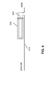
- the electrode line 20 likewise constitutes an implantable medical device.
- electrode poles in the form of a tip or tip electrode 22 and a ring electrode 24 arranged in the vicinity thereof are arranged in a manner known per se.
- the electrode poles 22 and 24 are designed such that, depending on the function of a cardiac stimulator to which the electrode lead 20 is connected, they serve to sense electrical potentials of the heart tissue (myocardium) or to emit electrical signals, for example to deliver stimulation pulses to the surrounding them Heart tissue, are formed.
- Fig. 1 shows how the electrode poles, so the tip electrode 22 and the ring electrode 24, in the application, the electrode line 20, located in the apex of a right ventricle of a heart.
- Both the tip electrode 22 and the ring electrode 24 are electrically connected via at least one electrical conductor 26 to a plug contact 28 at the proximal end of the electrode line 20.
- the plug contact 28 has electrical contacts which correspond to the electrical contacts 16 of the contact socket in the connection housing 14 of the implantable cardiac stimulator.
- the electrical conductors 26 in the electrode line 20 may be formed as approximately elongated Seilzugleiter or as a helical coiled conductor.
- Such conductors electrically conductively connect functional electrode poles to electrical contacts of the plug-in contact at the proximal end of the electrode line 20 are referred to as function conductors in the context of this text, since they transmit, for example, electrical signals from the plug contact to the respective electrode pole, or sensed signals representing electrical potential from the sensor lead respective electrode pole to the plug contact and thus serve the elementary function of the medical device.
- the electrical conductors 26, which connect the electrode poles 22 and 24, respectively, to the electrical contacts of the plug 28 of the electrode line 20, are surrounded over most of their length by an insulating sheath, so that an electrical contact to the tissue of the heart is targeted via the electrode poles comes about.
- the electrode line 20 In addition to the electrode poles 22 and 24, which typically serve the (in this case, ventricular) stimulation of the heart tissue, the electrode line 20 also has two larger-area electrode poles 30 and 32, which serve as defibrillation electrodes and are formed by at least one bare helix-like coiled wire ,
- an ablation electrode lead can in principle also be used, which likewise projects into the heart of a patient in the application and which is controlled by a device arranged outside the patient and is connected to it for this purpose.
- FIG. 2 Figure 1 shows a typical temperature curve 100 of a conventional pacemaker / ICD electrode in magnetic resonance imaging (MRI).
- MRI magnetic resonance imaging
- FIG. 3 the structural design of the ferrite-free standing wave barrier is shown.
- the conductor 210 is drawn in a stretched manner; in general, the conductors can also be coiled.
- the line section in the region of the reference numeral 250 forms a double-lead section, in which a dielectric 230 separates the conductors, namely the function conductor 210 and the additional conductor 220 from one another.
- the line section 250 - also referred to below as a double line - can be realized as a coaxial conductor, parallel conductor, stripline or the like, the embodiments with coaxial conductor being described below without excluding the generality.
- the functional conductor 210 within the double lead portion 250 forms a coax inner conductor and the auxiliary conductor is the coaxial outer conductor 220.
- this conductor section is coiled.
- the realization is such that the geometric distance bridged by the capacitor 240 is short compared to the wavelength in the double line for the highest operating frequency (preferably factor ⁇ 1/10).
- a feature of this invention is that such a helix can also be realized in the case of rope electrodes to realize this short distance.
- Another preferred variant is in FIG. 4 shown.
- the capacitance C 240 couples the field emerging at the distal end of the coaxial outer conductor 220 backwards in a short electrical path to the proximal input into the coaxial section 220 and thus suppresses the envelope wave. Due to the skin effect, the high-frequency signals are conducted on the surface or the fields even propagate through the surrounding insulation (displacement currents). One speaks therefore of sheath waves. By contrast, the low-frequency therapy currents flow inside the conductor. With the barrier according to the invention, only the mantle shafts are to be blocked, which thus transport the unwanted HF energy.
- FIG. 4 shows a preferred installation of a standing wave trap in an electrode line.
- the sheath wave barrier realized from 220 and 240 (in between the dielectric - not shown here) is preferably mounted near the distal end of the electrode lead, preferably in the distal-side half of the electrode lead
- Characteristic of the invention is that the one conductor of the double line is realized by the therapeutic conductor (the function conductor) of the electrode lead itself, dielectric and second conductor (additional conductor) are guided only next door or around it, i. without the therapeutic conductor must be mechanically interrupted.
- the capacitor connects the ends of the additional conductor.
- the contacting here is only relevant for the MR properties of the electrode but not for its life-long therapeutic reliability.
- the interconnection of the thus constructed double line with the capacitor 240 in the manner described realizes a sheath wave barrier. According to the invention, this is realized so that it is resonant at at least one frequency. At this resonance frequency or at the plurality of resonance frequencies, the effect is maximum. According to the invention, these resonance frequencies are set so that they are close to the operating frequency of common MRI devices (see Table 1) in such a way that the bandwidths of these resonances max. 10 MHz.
- ferrites are used as sheath wave barriers for the frequency range of conventional MRI devices.
- FIG. 5 the equivalent circuit of the ferrite-free standing wave barrier according to the invention is shown, which in the embodiment in FIG. 3 is designed as a coaxial line section.
- the inner conductor is represented by the inductance 330 and the outer conductor by the inductance 340, the dielectric via the coupling capacitors 310, 320.
- the additional capacitance 350 causes a phase shift and thus destructively couples the sheath wave back. It is important to mention that, although the coaxial inner conductor shown in the equivalent circuit diagram as an inductance 330, but not structurally interrupted by an additional component or the coupling capacitors shown 320 are connected to this therapy-leading function guide.
- FIG. 6 shows a more detailed equivalent circuit in the form of a splice model, which represents the double line discretized as an LC network. It is also considered that the elements are really lossy (not shown, but considered in the Spice model).
- the capacitance indicated by 240 or 350 in the previous figures is called C21 here.
- the resistor and the voltage source belong to the measuring circuit which explains the operation. The current flowing through the measuring resistor R2 would flow into the tissue in the case of a real electrode and heat it accordingly during MR imaging.
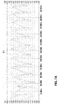
- FIG. 7A shows the result of a simulation based on the splice model FIG. 6 for a multi-resonant standing wave trap according to the invention, which is optimized to ensure that the same electrode is effectively protected in all 3 MRT devices listed in Table 1.
- the effect is particularly pronounced at the frequencies where the current is strongly attenuated. Shown are amplitudes and phase position of the current in the measuring resistor.
- FIG. 7B shows the result of a similar simulation in which the modeled standing wave trap uses an inductance instead of the capacitor 240 or C21.
- Table 1 Frequency (MHz) / MR magnetic field strength (T) Attenuation (dB) of the current relative to a signal at 1 kHz Reduction of warming by (%) 63.5 MHz / 1.5T 34.5 dB 99.9% 126.9 MHz / 3T 20.3 dB 99.0% 296.1 MHz / 7T 17 dB 98.0%
- Table 1 shows operating frequencies at a gyromagnetic ratio of 42.3 MHz / T for protons.
- the effect of FIG. 7A underlying embodiment variant is given with respect to a therapeutic / diagnostic useful signal at 1 kHz, since up to this frequency for therapeutic and diagnostic reasons, the electrode must function as undamped as possible
- the resonances of the standing wave barrier according to the invention are physically conditioned in certain frequency spacing ratios. Therefore, the desired operating frequencies of MR devices can not all be met equally well. However, the optimization of the components shown in Fig. 4 (in particular also with regard to the losses intended here for broadening the resonance low) makes possible a good compromise.
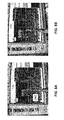
- FIG. 8 A realization form constructed as a helix is FIG. 8 shown.
- the illustrated implementation is only an example, so here the resonance is not at a typical MR frequency but can easily be tuned to it via a corresponding capacitor.
- FIG. 8 illustrated embodiment shows a coiled realization of the standing wave barrier in coaxial technology. on the screen behind it, the impedance is plotted and a clear peak can be seen when the capacitor 240 joins the coaxial outer conductor at its ends ( FIG. 8a ). This is not the case if the capacitor is missing ( FIG. 8b ).
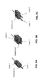
- FIGS. 9A to 9C show various embodiments of a double line.
- the double lead portion is formed as a coaxial conductor.
- the double lead portion formed as a parallel line of two flat conductors.
- the double lead portion is formed as a parallel line of two strip conductors.
Abstract
Description
- Die Erfindung betrifft ein permanent oder temporär implantierbares Gerät mit einem langgestreckten elektrischen Leiter.
- Solche Geräte, beispielsweise Elektrodenleitungen für die Elektrostimulation oder Katheter für elektrophysiologische Interventionen, haben den Nachteil, dass sich ihr elektrischer Leiter in einem Kernspintomografen erwärmen kann, weil die im Kernspintomografen herrschenden wechselnden Magnetfelder in dem elektrischen Leiter nicht unbeachtliche elektrische Ströme induzieren. Auch können solche induzierten Ströme über Elektrodenpole der Elektrodenleitung an umliegendes Gewebe abgegeben werden und so beispielsweise zu unerwünschten Gewebeerwärmungen führen. Deshalb können Herzschrittmacherpatienten heutzutage in der Regel nicht oder nur eingeschränkt in einem Kernspintomografen untersucht werden.
- An implantierbaren Herzschrittmachern oder Defibrillatoren (im Folgenden auch gemeinsam als Herzstimulatoren oder IPG (implantable pulse generator) bezeichnet) sind nämlich typischerweise wenigstens eine Stimulationselektrodenleitung angeschlossen, die an ihrem proximalen, zum Anschluss an den Herzschrittmacher oder Defibrillator vorgesehenen Ende einen standardisierten elektrischen Anschluss aufweist und an ihrem distalen, zur Platzierung im Herzen vorgesehenen Ende einen oder mehrere Elektrodenpole aufweist. Ein solcher Elektrodenpol dient zur Abgabe elektrischer Impulse an das Gewebe (Myokard) des Herzens oder zum Abfühlen elektrischer Felder, um im Rahmen des sogenannten Sensings eine Aktivität eines Herzens abfühlen zu können. Zu diesen Zwecken bilden Elektrodenpole typischerweise elektrisch leitende Oberflächenabschnitte einer Elektrodenleitung. Elektrodenpole sind typischerweise als Ringelektrode in Form eines Rings um die Elektrodenleitung oder in Form einer Spitzen- oder Tippelektrode am distalen Ende der Elektrodenleitung vorgesehen. Die Elektrodenpole sind über eine oder mehrere elektrische Leiter mit Kontakten des elektrischen Anschlusses der Elektrodenleitung an deren proximalem Ende elektrisch leitend verbunden. Somit verlaufen zwischen den Kontakten des elektrischen Anschlusses die Elektrodenleitungen an deren proximalen Ende und den Elektrodenpolen am distalen Ende der Elektrodenleitung ein oder mehrere elektrische Leiter, die einen oder mehrere der Elektrodenpole mit einem oder mehreren der Kontakte elektrisch verbinden. Diese elektrischen Leiter können einerseits zur Übertragung von Stimulationsimpulsen zu den Elektrodenpolen und andererseits zur Übertragung mittels der Elektrodenpole aufgenommener elektrischer Signale zum proximalen Ende der Elektrodenleitung genutzt werden und werden im Verlauf der weiteren Beschreibung auch jeweils als Funktionsleitung bezeichnet. Solche Funktionsleitungen sind für die Funktionen der jeweiligen Elektrodenleitung erforderliche elektrische Leiter und als solche der Gefahr ausgesetzt, dass in ihnen durch äußere Wechselmagnetfelder elektrische Ströme induziert werden, die beispielsweise zu einer unerwünschten Erwärmung der Funktionsleitungen oder der mit ihr verbundenen Elektrodenpole führen können oder die zur Abgabe entsprechender Ströme über die Elektrodenpole an umgebendes Gewebe und damit zu einer Erwärmung des umgebenden Gewebes führen können.
- Der Erfindung liegt die Aufgabe zugrunde, ein Gerät zu schaffen, welches das zuvor beschriebene Problem löst.
- Erfindungsgemäß wird diese Aufgabe durch ein temporär oder permanent implantierbares medizinisches Gerät mit wenigstens einem langgestreckten elektrischen Funktionsleiter für die Übertragung von Therapiesignalen oder Diagnosesignalen oder beidem, wobei wenigstens ein Zusatzleiter vorgesehen ist, der zusammen mit dem Funktionsleiter wenigstens abschnittsweise eine Doppelleitung bildet, von dem Funktionsleiter durch ein Dielektrikum getrennt ist und der mit dem Funktionsleiter über eine Koppelimpedanz gekoppelt ist. Die Koppelimpedanz ist so bemessen, dass der Wert des Leitungswellenwiderstands des Funktionsleiters für Frequenzbereiche weit oberhalb eines Frequenzbereichs der Therapie- oder Diagnosesignale wesentlich größer ist, als der Wert des Leitungswellenwiderstands des Funktionsleiters im Frequenzbereich der Therapie- oder Diagnosesignale, so dass Ströme in einem oberhalb des Frequenzbereichs der Therapie- oder Diagnosesignale stärker bedämpft werden, als die Therapie- oder Diagnosesignale bildenden Ströme.
- Es sei bereits hier darauf hingewiesen, dass im Folgenden die Begriffe Funktionsleiter und therapieführender Leiter synonym verwendet werden.
- Der Wellenwiderstand ist ein Maß für den wellenlängen-abhängigen Wert des elektrischen Widerstands von HF-Kabeln.
- Bei Koaxialkabeln ist der Wellenwiderstand unabhängig von der Kabellänge aber abhängig vom Kapazitäts- und Induktivitätsbelag des HF-Kabels. Diese Werte sind direkt abhängig vom Durchmesser des Innenleiters und der Schirmung und von der Dielektrizitätskonstanten des Dielektrikums. Kapazitäts- und Induktivitätsbelag eines HF-Kabels können im Ersatzschaltbild durch eine Reihenschaltung von vielen einzelnen Induktivitäten und eine Parallelschaltung ebenso vieler Kapazitäten nachgebildet werden. Unter Vernachlässigung des ohmschen Widerstands ergibt sich der Wellenwiderstand (Z) näherungsweise aus der Wurzel des Verhältnisses von Induktivität zur Kapazität.
- Die Erfindung schließt den Gedanken ein, den Wellenwiderstand eines Funktionsleiters so einzustellen, dass der Funktionsleiter für Frequenzbereiche, die denjenigen zu erwartender Störfelder entsprechen, einen hohen Wellenwiderstand besitzt und Ströme dieser Frequenz entsprechend dämpft.
- In Fortführung des Erfindungsgedankens wird dies durch eine entsprechend ausgelegte Mantelwellensperre erreicht und zwar vorzugsweise indem der eine Doppelleitung bildende Abschnitt des medizinischen Gerätes als Mantelwellensperre ausgebildet ist.
- Das medizinische Gerät ist vorzugsweise eine Elektrodenleitung zum Anschluss an einen implantierbaren Herzstimulator.
- Alternativ ist das medizinische Gerät ein Katheter für elektrophysiologische Interventionen oder eine Elektrodenleitung für einen temporären Herzstimulator.
- Vorzugsweise ist die Koppelimpedanz zwischen Funktionsleiter und Zusatzleiter von einer Kapazität gebildet. Alternativ oder zusätzlich kann die Koppelimpedanz auch von einer Induktivität und/oder einem Kurzschluss gebildet sein.
- Gemäß alternativer vorteilhafter Ausgestaltungen kann der als Doppelleitung ausgebildete Abschnitt des medizinischen Gerätes als Koaxial-, als Parallelleitung, Stripline oder dergleichen aufgebaut sein.
- Besonders bevorzugt ist eine Ausführungsvariante der Erfindung bei der der als Doppelleitung ausgebildete Abschnitt des medizinischen Geräts in dieses konstruktiv so integriert ist, dass die geometrische Strecke zwischen Funktionsleiter und Zusatzleiter, die von der Koppelimpedanz (z.B. einem Kondensator) überbrückt wird, kurz ist im Vergleich zur Wellenlänge in der Doppelleitung für eine vorgegebene höchste Arbeitsfrequenz. Das Verhältnis geometrische Strecke zwischen Funktionsleiter und Zusatzleiter zur Wellenlänge bei vorgesehener höchster Arbeitsfrequenz ist vorzugsweise kleiner als ein Zehntel (1/10).
- Besonders bevorzugt ist eine Ausführungsvariante, bei der das medizinische Gerät ein- oder mehrpolarer, temporär anwendbarer Katheter oder eine dauerimplantierbare Elektrodenleitung oder ein langgestrecktes elektrisch leitfähiges Implantat mit einer teilweisen Isolation ist, so dass an definierten Elektrodenflächen eine lokale Erwärmung durch im MRT induzierte Ströme zu erwarten ist. Hierbei ist proximal eines Elektrodenpoles zumindest abschnittsweise um den oder nahe an dem Zuleitungsdraht (therapieführender Leiter, hier als Funktionsleiter bezeichnet) ein zweiter Leiter (hier als Zusatzleiter bezeichnet) angeordnet, der zusammen mit dem therapieführenden Leiter auf diesem Abschnitt eine Doppelleitung bildet, wobei die Leiter durch ein Dielektrikum (230) voneinander isoliert sind. Die Enden des zweiten Leiters, also des Zusatzleiters, sind über eine Impedanz miteinander verbunden, deren Wert in Abhängigkeit der Induktivitäts- und Kapazitätsbeläge des Doppelleitungsabschnitts so bestimmt ist, dass die therapeutische Zuleitung für Frequenzen wesentlich höher als die von Therapie- und Diagnosesignalen eine hohe Impedanz aufweist (bzw. hier Ströme stark dämpft) und zwar für zumindest eine MR typische HF Frequenz mit dem Ziel, die unerwünschte Implantats/Elektrodenerwärmung während der MR Bildgebung/Spektroskopie zu reduzieren/vermeiden.
- Vorzugsweise ist der Doppelleitungsabschnitt ist so realisiert, dass der eine Leiter der therapieführende Funktionsleiter selbst ist, der zur Realisierung der Mantelwellensperre nicht unterbrochen ist, indem die Mantelwellensperre um den Funktionsleiter herum oder diesem unmittelbar benachbart angeordnet ist. Es ist dann keine potentiell unzuverlässige Kontaktierungstechnik am therapieführenden Leiter (Funktionsleiter) selbst erforderlich.
- Vorzugsweise ist der Doppelleitungsabschnitt gewendelt, d.h. helixförmig konstruiert.
besonders bevorzugt ist eine Ausführungsvariante, bei der der Doppelleitungsabschnitt eine Schleife bildet, die parallel zu dem Funktionsleiter oder den Funktionsleitern, also den therapieführenden Leitern, in der Elektrodenzuleitung geführt ist oder bei gewendelten E-lektrodenleitungskonstruktionen in die Wendellücken mitgewendelt ist. - Im Falle von Seilelektroden, bei denen der therapieführende Funktionsleiter ein Seilleiter ist, ist es bevorzugt, wenn der Funktionsleiter wird im Doppelleitungsabschnitt (koaxialen Abschnitt) als Wendelstruktur ausgeführt ist, so dass Der Funktionsleiter ist in dem als Doppelleitung ausgebildeten Abschnitt des medizinischen Gerätes helixartig gewendelt ist.
- Als Dielektrikum wird vorzugsweise die Isolation des therapieführenden Leiters, also des Funktionsleiters, selbst genutzt. Der zweite Leiter der Doppelleitung, also der Zusatzleiter, kann dann durch Metallisierung des Dielektrikums (z.B. durch Aufdampfen einer Metallschicht) realisiert und somit beispielsweise von einer aufgedampften Metallschicht gebildet sein. Aus dieser Weise ergibt sich ein ebenso einfacher wie kompakter Aufbau des Doppelleitungsbschnitts.
- Alternativ kann der Zusatzleiter, z.B. der koaxiale Außenleiter aus einem flexiblen, leitfähigen Polymer oder Liquid Cristal Polymer (LCP) bestehen.
- Auch kann der Doppelleitungsabschnitt als getrennt gefertigtes Bauelement in die Elektrodenleitung eingebaut sein (mit herkömmlicher Verbindungstechnik).
- Vorzugweise hat der Doppelleitungsabschnitt einen Wellenwiderstand von weniger als 120 Ohm.
- Der Doppelleitungsabschnitt kann auch durch diskrete Bauelemente realisiert sein, und zwar vorzugsweise mit weniger als 20 Teilabschnitten (d.h. "La-Cc-Lb-Zellen") so wie es sich aus dem Ersatzschaltbildern in
Figuren 5 und6 ergibt. - Der Doppelleitungsabschnitt kann auch (hybrid) als Leitung aber mit längs der Leitung ein oder mehrfach unterbrochenem Dielektrikum ausgeführt sein, so dass die Kondensatoren Cc diskret realisiert sind.
- Der Doppelleitungsabschnitt ist vorzugsweise so aufgebaut, dass die Verluste (Längswiderstände der Leiter, d.h. die der Induktivitäten La und Lb oder Parallelwiderstände der Kapazitäten Cc, siehe Abb4) so abgestimmt sind, dass die Bandbreite um die Resonanzfrequenz(en) weniger als 10 MHz betragen.
- Die erfindungsgemäße Mantelwellensperre ist vorzugsweise so aufgebaut, dass die durch sie hervorgerufene Dämpfung des (wärmeerzeugenden) Stroms für die jeweilige Larmorfrequenz der MR Bildgebung oder Spektroskopie größer als 6 dB ist.
- Vorzugsweise liegt das Verhältnis der Induktivitätsbeläge der einzelnen Leiter der Doppelleitung (entspricht dem Verhältnis La/Lb in
Figur 6 ) zwischen 0.1 und 10, und ist bevorzugt Lb/La = 0,75. - Der Doppelleitungsabschnitt ist vorzugsweise so aufgebaut, dass durch die Parameter der vom Doppelleitungsabschnitt gebildeten Mantelwellensperre die Frequenzabstände der Resonanzen so optimiert sind, dass möglichst viele HF Arbeitsfrequenzen von MRT Geräten mit derselben Mantelwellensperre (und damit der selben Elektrodenleitung) getroffen werden. Bevorzugt liegen die Resonanzen möglichst eng beieinander, mit einem Frequenzabstand von weniger als 25 MHz.
- Die Erfindung soll nun anhand von Ausführungsbeispielen mit Bezug auf die Figuren näher erläutert werden. Die Figuren zeigen Folgendes:
- Fig. 1
- zeigt als implantierbare medizinische Geräte einen implantierbaren Herzstimulator 10 und eine daran angeschlossene implantierbare Elektrodenleitung 20.
- Fig. 2
- zeigt beispielhaft einen Temperaturverlauf an der Elektrodenspitze unter Einfluss von hochfrequenten Wechselfeldern, wie sie in einem Kernspintomografen (MRT) herrschen.
- Fig. 3
- zeigt den konstruktiven Aufbau einer ferritfreien Mantelwellensperre.
- Fig. 4
- zeigt einen bevorzugten Einbau einer Mantelwellensperre in eine Elektrodenleitung.
- Fig. 5
- zeigt ein vereinfachtes Ersatzschaltbild der erfindungsgemäßen Realisierung einer Mantelwellensperre.
- Fig. 6
- zeigt ein detaillierteres Ersatzschaltbild (Spice-Modell), das die Doppelleitung diskretisiert als ein LC Netzwerk darstellt.
- Fig. 7A und 7B
- zeigen das Verhalten zweier Elektrodenleitungen mit unterschiedlich ausgeführter Mantelwellensperre.
- Fig. 8A und 8B
- zeigen eine als Wendel konstruierte Realisierungsform einer Mantelwellensperre in Koaxialtechnik.
- Figuren 9A bis 9C
- zeigen verschiedene Ausführungsbeispiele einer Doppelleitung.
- Der implantierbare Herzstimulator 10 kann ein Herzschrittmacher oder ein Kardioverter/Defibrillator (ICD) sein. Im dargestellten Ausführungsbeispiel ist der Herzstimulator 10 ein ventrikulärer Herzschrittmacher und Defibrillator. Andere bekannte Herzstimulatoren sind Zweikammerherzschrittmacher zur Stimulation des rechten Atriums und des rechten-Ventrikels oder biventrikuläre Herzschrittmacher, die zusätzlich zum rechten Ventrikel auch den linken Ventrikel stimulieren können.
- Derartige Stimulatoren besitzen typischerweise ein Gehäuse 12, das im Regelfall aus Metall besteht und somit elektrisch leitend ist und als großflächiger Elektrodenpol dienen kann. An der Außenseite des Gehäuses 12 ist typischerweise ein Anschlussgehäuse 14 befestigt, das auch als Header bezeichnet wird. Ein derartiger Header weist typischerweise Kontaktbuchsen zur Aufnahme von Steckkontakten auf. Die Kontaktbuchsen besitzen elektrische Kontakte 16, die über entsprechende Leiter mit einer in dem Gehäuse 12 des Herzstimulators 10 angeordneten Elektronik verbunden sind.
- Die Elektrodenleitung 20 stellt im Sinne dieser Erfindung ebenfalls ein implantierbares medizinisches Gerät dar. Am distalen Ende der Elektrodenleitung 20 sind in an sich bekannter Manier Elektrodenpole in Form einer Spitzen- oder Tipelektrode 22 und einer in deren Nähe angeordneten Ringelektrode 24 angeordnet. Die Elektrodenpole 22 und 24 sind so ausgebildet, dass sie je nach Funktion eines Herzstimulators, an den die Elektrodenleitung 20 angeschlossen ist, zum Abfühlen elektrischer Potenziale des Herzgewebes (Myokards) dienen oder zur Abgabe elektrischer Signale, beispielsweise zur Abgabe von Stimulationsimpulsen an das sie umgebende Herzgewebe, ausgebildet sind.
Fig. 1 zeigt, wie sich die Elektrodenpole, also die Tipelektrode 22 und die Ringelektrode 24, im Anwendungsfall die Elektrodenleitung 20, im Apex eines rechten Ventrikels eines Herzens befinden. - Sowohl die Tipelektrode 22 als auch die Ringelektrode 24 sind über jeweils wenigstens einen elektrischen Leiter 26 mit einem Steckkontakt 28 am proximalen Ende der Elektrodenleitung 20 elektrisch verbunden. Der Steckkontakt 28 besitzt elektrische Kontakte, die mit den elektrischen Kontakten 16 der Kontaktbuchse im Anschlussgehäuse 14 des implantierbaren Herzstimulators korrespondieren. Die elektrischen Leiter 26 in der Elektrodenleitung 20 können als annähernd gestreckte Seilzugleiter oder als helixförmig gewendelte Leiter ausgebildet sein. Solche Leiter, die funktionale Elektrodenpole mit elektrischen Kontakten des Steckkontaktes am proximalen Ende der Elektrodenleitung 20 elektrisch leitend verbinden werden im Rahmen dieses Textes als Funktionsleiter bezeichnet, da sie beispielsweise der Therapie dienende elektrische Signale von Steckkontakt zum jeweiligen Elektrodenpol übertragen oder abgefühlte elektrische Potentiale repräsentierende Signale vom jeweiligen Elektrodenpol zum Steckkontakt führen und somit der elementaren Funktion des medizinischen Gerätes dienen.
- Die elektrischen Leiter 26, die die Elektrodenpole 22 bzw. 24 mit den elektrischen Kontakten des Steckers 28 der Elektrodenleitung 20 verbinden, sind über den größten Teil ihrer Länge von einer isolierenden Hülle umgeben, so dass ein elektrischer Kontakt zum Gewebe des Herzens gezielt über die Elektrodenpole zustande kommt.
- Neben den Elektrodenpolen 22 und 24, die typischerweise der (in diesem Fall ventrikulären) Stimulation des Herzgewebes dienen, weist die Elektrodenleitung 20 auch noch zwei großflächigere Elektrodenpole 30 und 32 auf, die als Defibrillationselektroden dienen und von wenigstens einem blank liegendem helixartig gewendelten Draht gebildet sind.
- Es sei darauf hingewiesen, dass die Erfindung im Rahmen dieses Ausführungsbeispiels anhand eines rechtsventrikulären Herzschrittmachers und Defibrillators erläutert wird. Als medizinisches Gerät im Sinne der Erfindung kann grundsätzlich aber beispielsweise auch eine Ablationselektrodenleitung dienen, die im Anwendungsfall ebenfalls bis ins Herz eines Patienten hineinragt und die von einem außerhalb des Patienten angeordneten Gerät gesteuert wird und hierzu mit diesem verbunden ist.
- In
Figur 2 ist ein typischer Temperaturverlauf 100 einer konventionellen Schrittmacher/ICD-Elektrode im Magnetresonanztomografen (MRT) dargestellt. Mit dem Einschalten des hochfrequenten Wechselfeldes im Tomografen zum Zeitpunkt 110 steigt die Temperatur rasch an, wobei die Steilheit des Anstieges und die maximal erreichbare Temperatur stark von der Elektrodenlage bezogen auf die hochfrequenten Wechselfelder des MRT abhängig ist. Wird das hochfrequente Wechselfeld abgeschaltet (zum Zeitpunkt 120), dann kühlt sich die Elektrodenspitze aufgrund ihrer vergleichsweise geringen Wärmekapazität verhältnismäßig schnell wieder ab. - In
Figur 3 ist die konstruktive Ausführung der ferritfreien Mantelwellensperre dargestellt. InFigur 3 ist der Leiter 210 der Einfachheit halber gestreckt gezeichnet, im Allgemeinen können die Leiter auch gewendelt sein. Der Leitungsabschnitt im Bereich des Bezugszeichens 250 bildet einen Doppelleitungsabschnitt, in dem ein Dielektrikum 230 die Leiter, nämlich den Funktionsleiter 210 und den Zusatzleiter 220 voneinander trennt. Der Leitungsabschnitt 250 - im Folgenden auch Doppelleitung genannt - kann als Koaxialleiter, Parallelleiter, Stripline oder dergleichen realisiert sein, wobei im Folgenden ohne Ausschluss der Allgemeinheit die Ausführungen mit Koaxialleiter beschrieben werden. In dem abgebildeten Ausführungsbeispiel bildet der Funktionsleiter 210 innerhalb des Doppelleitungsabschnitts 250 einen Koax-Innenleiter und der Zusatzleiter ist der Koax-Außenleiter 220. - Gemäß einer bevorzugten Realisierung ist dieser Leiterabschnitt gewendelt. Die Realisierung ist so, dass die geometrische Strecke, die der Kondensator 240 überbrückt, kurz ist im Vergleich zur Wellenlänge in der Doppelleitung für die höchste Arbeitsfrequenz (bevorzugt Faktor <1/10). Ein Merkmal dieser Erfindung ist es, dass so eine Wendel auch im Falle von Seil-Elektroden realisiert werden kann, um diesen kurzen Abstand zu realisieren. Eine andere bevorzugte Variante ist in
Figur 4 gezeigt. - Die Kapazität C 240 koppelt das am distalen Ende des koaxialen Außenleiters 220 herauskommende Feld auf kurzem elektrischem Weg phasenverkehrt an den proximalen Eingang in den koaxialen Abschnitt 220 zurück und unterdrückt somit die Mantelwelle. Die hochfrequenten Signale werden wegen des Skineffekts an der Oberfläche geleitet bzw. die Felder pflanzen sich gar durch die umliegende Isolation (Verschiebungsströme) fort. Man spricht daher von Mantelwellen. Die niederfrequenten Therapieströme fließen hingegen im Inneren des Leiters. Mit der erfindungsgemäßen Sperre sollen nur die Mantelwellen geblockt werden, die also die unerwünschte HF Energie transportieren.
-
Figur 4 zeigt einen bevorzugten Einbau einer Mantelwellensperre in eine Elektrodenleitung. Die Mantelwellensperre realisiert aus 220 und 240 (dazwischen das Dielektrikum - hier nicht gezeigt) ist bevorzugt nahe des distalen Endes der Elektrodenleitung montiert, bevorzugt in der distal-seitigen Hälfte der Elektrodenleitung - Kennzeichnend für die Erfindung ist, dass der eine Leiter der Doppelleitung durch den therapeutischen Leiter (den Funktionsleiter) der Elektrodenzuleitung selbst realisiert ist, Dielektrikum und Zweitleiter (Zusatzleiter) nur nebenan oder rundherum geführt sind, d.h. ohne das der therapeutische Leiter mechanisch unterbrochen werden muss. Dies ist ein entscheidendes Zuverlässigkeitsmerkmal der erfindungsgemäßen Lösung. Der Kondensator verbindet die Enden des Zusatzleiters. Die Kontaktierung hier ist nur für die MR-Eigenschaften der Elektrode relevant nicht aber für ihre lebens-lange therapeutische Zuverlässigkeit.
- Die Verschaltung der so konstruierten Doppelleitung mit dem Kondensator 240 in der beschriebenen Weise realisiert eine Mantelwellensperre. Gemäß der Erfindung ist diese so realisiert, dass sie bei mindestens einer Frequenz resonant ist. Bei dieser Resonanzfrequenz bzw. bei den mehreren Resonanzfrequenzen ist die Wirkung maximal. Erfindungsgemäß sind diese Resonanzfrequenzen so gelegt, dass sie nahe der Arbeitsfrequenz gängiger MRT Geräte liegen (siehe Tabelle 1) und zwar so, dass die Bandbreiten dieser Resonanzen max. 10 MHz betragen.
- Nach dem Stand der Technik werden als Mantelwellensperren für den Frequenzbereich üblicher MRT-Geräte Ferrite eingesetzt. Diese sättigen jedoch im statischen Feld des MRT und werden damit unwirksam. Daher ist es Ziel dieser Erfindung eine Lösung ohne Ferrite auszuarbeiten.
- Eine beschriebene Implementierung ist die gewendelte Ausführung. In der Regel reichen wenige Wicklungen aus, dann braucht auch die Kapazität C 240 keine langen Zuleitungen, die sonst eine unerwünschte parasitäre Induktivität hätten. Eine Konstruktionsvariante ist beispielhaft in
Figur 8 dargestellt. - In
Figur 5 ist das Ersatzschaltbild der erfindungsgemäßen ferritfreien Mantelwellensperre dargestellt, die bei dem Ausführungsbeispiel inFigur 3 als koaxialer Leitungsabschnitt ausgebildet ist. In dem Ersatzschaltbild sind der Innenleiter durch die Induktivität 330 und Außenleiter durch die Induktivität 340 dargestellt, das Dielektrikum über die Koppelkondensatoren 310, 320. Die zusätzliche Kapazität 350 bewirkt eine Phasenverschiebung und koppelt so die Mantelwelle destruktiv zurück. Wichtig ist zu erwähnen, dass sich zwar der koaxiale Innenleiter im Ersatzschaltbild als eine Induktivität 330 dargestellt, konstruktiv aber nicht durch ein zusätzliches Bauelement unterbrochen ist oder die gezeigten Koppelkapazitäten 320 mit diesem therapieführenden Funktionsleiter verbunden sind. -
Figur 6 zeigt ein detaillierteres Ersatzschaltbild in Form eines Splice-Modells, das die Doppelleitung diskretisiert als ein LC Netzwerk darstellt. Berücksichtigt ist auch, dass die Elemente real verlustbehaftet sind (nicht dargestellt, aber im Spice Modell berücksichtigt). Die in den vorigen Figuren mit 240 oder 350 bezeichnete Kapazität heißt hier C21. Der Widerstand und die Spannungsquelle gehören zur Messschaltung die die Funktionsweise erläutert. Der Strom der durch den Messwidersand R2 fließt würde im Falle einer realen Elektrode in das Gewebe fließen und es entsprechend während MR Bildgebung erwärmen. -
Figur 7A zeigt das Ergebnis einer Simulation auf Basis des Splice-Modells ausFigur 6 für eine multiresonante Mantelwellensperre nach erfindungsgemäßen Prinzip, die dafür optimiert ist, dass dieselbe Elektrode bei allen 3 in Tabelle 1 angegebenen MRT Geräten wirksam geschützt ist. Die Wirkung ist bei den Frequenzen besonders ausgeprägt, wo der Strom stark gedämpft wird. Gezeigt sind Amplituden und Phasenlage des Stroms im Messwiderstand. -
Figur 7B zeigt das Ergebnis einer ähnlichen Simulation, bei der die modellierte Mantelwellensperre statt des Kondensators 240. bzw. C21 eine Induktivität verwendet. Hier wird nur phänomenologisch die ähnliche Wirkung gezeigt. Über entsprechende Parameteranpassungen können auch auf diesem Wege die Wunschfrequenzen getroffen werden.Tabelle 1 Frequenz (MHz) / MR Magnetfeldstärke (T) Dämpfung (dB) des Stroms bezogen auf ein Signal bei 1 kHz Reduktion der Erwärmung um (%) 63.5 MHz / 1.5 T 34.5 dB 99.9 % 126.9 MHz / 3 T 20.3 dB 99.0 % 296.1 MHz / 7 T 17 dB 98.0 % - Tabelle 1 zeigt Arbeitsfrequenzen bei einem gyromagnetischen Verhältnis von 42.3 MHz/T für Protonen. Die Wirkung der
Figur 7A zugrunde liegenden Ausführungsvariante wird bezogen auf ein therapeutisch/diagnostisches Nutzsignal bei 1KHz angegeben, da bis zu dieser Frequenz aus therapeutischen und diagnostischen Gründen die Elektrode möglichst ungedämpft funktionieren muss - Die Resonanzen der erfindungsgemäßen Mantelwellensperre liegen physikalisch-bedingt in bestimmten Frequenzabstandsverhältnissen. Daher können die gewünschten Arbeitsfrequenzen von MR Geräten nicht alle gleichgut getroffen werden. Die Optimierung der in Abb4 dargestellten Komponenten (insbesondere auch hinsichtlich der hier gewollten Verluste zur Verbreiterung des Resonanztiefs) ermöglicht jedoch einen reichlich guten Kompromiss.
- Eine diesbezüglich bevorzugte Realisierung ist wie folgt, wobei die Leitung in 40 Segmente diskretisiert ist. Die real zu verwendende Leitung muss so konstruiert sein, dass sie das gleiche verhalten aufweist wie dies Ersatzschaltbild mit folgenden Werten:
- Leiterteilinduktivitäten
- La=7.4e-9 (H);
- Lb=0.75*La (H);
- Mit folgenden seriellen Verlustwiderständen
- RLa=0.1 (Ohm);
- RLb=0.1 (Ohm);
- Die Leitung soll einen Wellenwiderstand von
- Z0=18.75 (Ohm);
- Haben, daraus errechnet sich die, Querkapazität pro Segment
- Cc=(La+Lb)/Z0^2 (F);
- Mit einem Parallelen Verlustwiderstand von
- CcRp=1e6 (Ohm);
- Der hier angenommene Quellenwiderstand (ist gleichzeitig der Messwiderstand) ist Rq=20 Ohm;
- Eine als Wendel konstruierte Realisierungsform ist
Figur 8 gezeigt. Die abgebildete Realisierung ist nur beispielhaft, daher ist hier die Resonanz nicht bei einer typischen MR Frequenz kann aber über einen entsprechenden Kondensator leicht darauf abgestimmt werden. Die inFigur 8 dargestellte Ausführungsform zeigt eine gewendelten Realisierung der Mantelwellensperre in Koaxialtechnik. auf dem dahinter abgebildeten Bildschirm ist die Impedanz aufgetragen und ein deutlicher Peak zu erkennen wenn der Kondensator 240 den Koax-Außenleiter an seinen Enden zusammenschließt (Figur 8a ). Dies ist nicht der Fall wenn der Kondensator fehlt (Figur 8b ). -
Figuren 9A bis 9C zeigen verschiedene Ausführungsbeispiele einer Doppelleitung. InFigur 9A ist der Doppelleitungsabschnitt als Koaxialleiter ausgebildet. InFigur 9B ist der Doppelleitungsabschnitt als Parallelleitung zweier Flachleiter ausgebildet. InFigur 9C ist der Doppelleitungsabschnitt als Parallelleitung zweier Stripleiter ausgebildet.
Claims (15)
- Temporär oder permanent implantierbares medizinisches Gerät mit wenigstens einem langgestreckten elektrischen Funktionsleiter (210) für die Übertragung von Therapiesignalen oder Diagnosesignalen oder beidem, dadurch gekennzeichnet, dass wenigstens ein Zusatzleiter (220) vorgesehen ist, der zusammen mit dem Funktionsleiter (210) wenigstens abschnittsweise eine Doppelleitung bildet, von dem Funktionsleiter (210) durch ein Dielektrikum getrennt ist und der mit dem Funktionsleiter (210) über eine Koppelimpedanz gekoppelt ist, die so bemessen ist, dass der Wert des Leitungswellenwiderstands des Funktionsleiters (210) für Frequenzbereiche weit oberhalb eines Frequenzbereichs der Therapie- oder Diagnosesignale wesentlich größer ist, als der Wert des Leitungswellenwiderstands des Funktionsleiters (210) im Frequenzbereich der Therapie- oder Diagnosesignale, so dass Ströme in einem oberhalb des Frequenzbereichs der Therapie- oder Diagnosesignale stärker gedämpft werden, als die Therapie- oder Diagnosesignale bildenden Ströme.
- Medizinisches Gerät nach Anspruch 1, dadurch gekennzeichnet, dass der eine Doppelleitung bildende Abschnitt des medizinischen Gerätes eine Mantelwellensperre bildet.
- Medizinisches Gerät nach Anspruch 1 oder 2, dadurch gekennzeichnet, dass das medizinische Gerät eine Elektrodenleitung (20) zum Anschluss an einen implantierbaren Herzstimulator (10) ist.
- Medizinisches Gerät nach einem der Ansprüche 1 bis 3, dadurch gekennzeichnet, dass die Koppelimpedanz von einer Kapazität (240, 350) gebildet ist.
- Medizinisches Gerät nach einem der Ansprüche 1 bis 4, dadurch gekennzeichnet, dass die Koppelimpedanz von einer Induktivität gebildet ist.
- Medizinisches Gerät nach einem der Ansprüche 1 bis 5, dadurch gekennzeichnet, dass der als Doppelleitung ausgebildete Abschnitt des medizinischen Gerätes als Koaxial-, als Parallelleitung, Stripline oder dergleichen aufgebaut ist.
- Medizinisches Gerät nach einem der Ansprüche 1 bis 6, dadurch gekennzeichnet, dass der als Doppelleitung ausgebildete Abschnitt des medizinischen Geräts in dieses konstruktiv so integriert ist, dass die geometrische Strecke zwischen Funktionsleiter (210) und Zusatzleiter (220), die von der Koppelimpedanz überbrückt wird, kurz ist im Vergleich zur Wellenlänge in der Doppelleitung für eine vorgegebene höchste Arbeitsfrequenz.
- Medizinisches Gerät nach einem der Ansprüche 1 bis 7, dadurch gekennzeichnet, dass der Zusatzleiter (220) proximal eines Elektrodenpols (22, 24, 30, 32) angeordnet ist und dem Funktionsleiter (210) zumindest abschnittsweise nahe benachbart ist oder diesen zumindest abschnittsweise umgibt, und so zusammen mit dem Funktionsleiter (210) auf diesem Abschnitt eine Doppelleitung bildet, wobei die Leiter durch ein Dielektrikum voneinander isoliert sind,
wobei die Enden des zweiten Leiters über eine Impedanz miteinander verbunden sind, deren Wert in Abhängigkeit der Induktivitäts- und Kapazitätsbeläge des Doppelleitungsabschnitts so bemessen ist, dass der Funktionsleiter (210) für Frequenzen wesentlich höher als die von Therapie- und Diagnosesignalen eine hohe Impedanz aufweist. - Medizinisches Gerät nach einem der Ansprüche 1 bis 8, dadurch gekennzeichnet, dass der Funktionsleiter (210) nicht unterbrochen und einstückig ist, und die Mantelwellensperre um den Funktionsleiter (210) herum oder diesem unmittelbar benachbart angeordnet ist.
- Medizinisches Gerät nach einem der Ansprüche 1 bis 9, dadurch gekennzeichnet, dass der Doppelleitungsabschnitt gewendelt ist.
- Medizinisches Gerät nach einem der Ansprüche 1 bis 10, dadurch gekennzeichnet, dass der Funktionsleiter (210) ist in dem als Doppelleitung ausgebildeten Abschnitt des medizinischen Gerätes helixartig gewendelt ist.
- Medizinisches Gerät nach einem der Ansprüche 1 bis 11, dadurch gekennzeichnet, dass der Doppelleitungsabschnitt eine Schleife bildet die parallel zu dem Funktionsleiter (210) geführt ist oder bei gewendeltem Funktionsleiter in die Wendellücken mitgewendelt ist.
- Medizinisches Gerät nach einem der Ansprüche 1 bis 12, dadurch gekennzeichnet, dass der Funktionsleiter (210) von einer Isolation umgeben ist, die das Dielektrikum bildet und Zusatzleiter (220) durch Metallisierung des Dielektrikums realisiert ist.
- Medizinisches Gerät nach einem der Ansprüche 1 bis 12, dadurch gekennzeichnet, dass der Außenleiter von einem flexiblen, leitfähigen Polymer oder Liquid Cristal Polymer (LCP) gebildet ist.
- Medizinisches Gerät nach einem der Ansprüche 1 bis 14, dadurch gekennzeichnet, dass der Doppelleitungsabschnitt einen Wellenwiderstand von weniger als 120 Ohm hat.
Applications Claiming Priority (1)
| Application Number | Priority Date | Filing Date | Title |
|---|---|---|---|
| US201061424073P | 2010-12-17 | 2010-12-17 |
Publications (3)
| Publication Number | Publication Date |
|---|---|
| EP2465572A2 true EP2465572A2 (de) | 2012-06-20 |
| EP2465572A3 EP2465572A3 (de) | 2013-01-16 |
| EP2465572B1 EP2465572B1 (de) | 2016-11-09 |
Family
ID=45217370
Family Applications (1)
| Application Number | Title | Priority Date | Filing Date |
|---|---|---|---|
| EP11191738.1A Not-in-force EP2465572B1 (de) | 2010-12-17 | 2011-12-02 | MRT-kompatible implantierbare Leitung |
Country Status (2)
| Country | Link |
|---|---|
| US (1) | US8942825B2 (de) |
| EP (1) | EP2465572B1 (de) |
Families Citing this family (7)
| Publication number | Priority date | Publication date | Assignee | Title |
|---|---|---|---|---|
| WO2013063796A1 (en) | 2011-11-04 | 2013-05-10 | Shanghai Microport Medical (Group) Co., Ltd. | Implantable active medical lead |
| US9199072B2 (en) | 2011-11-04 | 2015-12-01 | Shanghai Microport Medical (Group) Co., Ltd. | Implantable medical lead |
| EP2773419B1 (de) | 2011-11-04 | 2019-02-27 | Shanghai MicroPort Medical (Group) Co., Ltd. | Implantierbare medizinische passivelektrode |
| US9278210B2 (en) | 2012-06-28 | 2016-03-08 | Shanghai Microport Medical (Group) Co., Ltd. | Bipolar active cardiac electrical lead |
| CN103648580B (zh) * | 2012-06-28 | 2016-08-17 | 上海微创医疗器械(集团)有限公司 | 主动心脏电导线的组装 |
| WO2014000234A1 (en) * | 2012-06-28 | 2014-01-03 | Shanghai Microport Medical (Group) Co., Ltd. | Assembly of passive cardiac electrical lead |
| US8664153B1 (en) | 2013-03-15 | 2014-03-04 | Sociedad Oxidquimica Limitada | Activated carbon as an adsorbent composition |
Family Cites Families (7)
| Publication number | Priority date | Publication date | Assignee | Title |
|---|---|---|---|---|
| US8244370B2 (en) | 2001-04-13 | 2012-08-14 | Greatbatch Ltd. | Band stop filter employing a capacitor and an inductor tank circuit to enhance MRI compatibility of active medical devices |
| US8219208B2 (en) | 2001-04-13 | 2012-07-10 | Greatbatch Ltd. | Frequency selective passive component networks for active implantable medical devices utilizing an energy dissipating surface |
| CN101553165B (zh) | 2005-05-04 | 2011-05-18 | 波士顿科学神经调制公司 | 用于诸如可植入装置之类的电子装置的改良型电导线 |
| US7610101B2 (en) | 2006-11-30 | 2009-10-27 | Cardiac Pacemakers, Inc. | RF rejecting lead |
| ES2462741T3 (es) | 2007-03-19 | 2014-05-26 | Boston Scientific Neuromodulation Corporation | Cables compatibles con MRI y RF y métodos relacionados de operación y fabricación de cables |
| US8275464B2 (en) | 2007-12-06 | 2012-09-25 | Cardiac Pacemakers, Inc. | Leads with high surface resistance |
| US8818509B2 (en) | 2010-02-11 | 2014-08-26 | Biotronik Se & Co. Kg | Implantable element and electronic implant |
-
2011
- 2011-11-21 US US13/301,651 patent/US8942825B2/en active Active
- 2011-12-02 EP EP11191738.1A patent/EP2465572B1/de not_active Not-in-force
Non-Patent Citations (1)
| Title |
|---|
| None |
Also Published As
| Publication number | Publication date |
|---|---|
| US8942825B2 (en) | 2015-01-27 |
| EP2465572B1 (de) | 2016-11-09 |
| EP2465572A3 (de) | 2013-01-16 |
| US20120157810A1 (en) | 2012-06-21 |
Similar Documents
| Publication | Publication Date | Title |
|---|---|---|
| EP2465572B1 (de) | MRT-kompatible implantierbare Leitung | |
| EP2359896B1 (de) | Elektrodenvorrichtung zur Strom- oder Spannungsführung zwischen einem implantierbaren elektromedizinischen Gerät und einem Therapie- und/oder Diagnoseort im menschlichen Körper | |
| EP1923094B1 (de) | Elektrodenkatheter zu Interventionszwecken | |
| US8483840B2 (en) | Dual function tuned L-C input trap passive EMI filter component network for an active implantable medical device | |
| EP1923095B1 (de) | Elektrode zu Interventionszwecken | |
| EP2359895B1 (de) | Adaptionssonde zur Einführung in implantierte Elektrodenvorrichtungen aktiver medizinischer Implantate sowie Set bestehend aus einer implantierbaren Elektrodenvorrichtung und einer Adaptionssonde | |
| EP2468353B1 (de) | Implantierbares Gerät | |
| EP2578268B1 (de) | Temperatursensor für ein implantierbares medizinisches Gerät | |
| EP2985053A1 (de) | Implantierbare elektrische leitung | |
| EP2465569B1 (de) | Implantierbares Gerät | |
| EP2465573B1 (de) | Implantierbares Gerät | |
| EP2446922B1 (de) | Implantierbare Leiter mit zusätzlichen Leitern zur Feldentkopplung | |
| EP2478933A2 (de) | Implantierbares Gerät | |
| EP2985054B1 (de) | Implantierbares gerät mit elektrischem filter | |
| EP2465570B1 (de) | Implantierbares Gerät | |
| EP2478932A2 (de) | Implantierbares Gerät | |
| DE102020100121A1 (de) | Implantierbare Elektrode mit einer Stichleitung | |
| EP3025756B1 (de) | Im aktiven implantat integrierte elektrodenverlängerung | |
| EP2848282B1 (de) | Implantierbares Gerät | |
| EP2468356B1 (de) | Implantierbares Gerät | |
| EP2505229A2 (de) | Implantierbares Gerät | |
| EP2468354A2 (de) | Implantierbares Gerät | |
| EP2465571B1 (de) | Implantierbares Gerät | |
| WO2020192825A1 (de) | Antennenanordnung | |
| DE102019106675A1 (de) | Leitung für ein medizinisches Implantat, mit integrierten periodischen Induktionsspulen (iPIC) für verringerte Wechselwirkungen mit elektromagnetischen Feldern |
Legal Events
| Date | Code | Title | Description |
|---|---|---|---|
| PUAI | Public reference made under article 153(3) epc to a published international application that has entered the european phase |
Free format text: ORIGINAL CODE: 0009012 |
|
| AK | Designated contracting states |
Kind code of ref document: A2 Designated state(s): AL AT BE BG CH CY CZ DE DK EE ES FI FR GB GR HR HU IE IS IT LI LT LU LV MC MK MT NL NO PL PT RO RS SE SI SK SM TR |
|
| AX | Request for extension of the european patent |
Extension state: BA ME |
|
| PUAL | Search report despatched |
Free format text: ORIGINAL CODE: 0009013 |
|
| AK | Designated contracting states |
Kind code of ref document: A3 Designated state(s): AL AT BE BG CH CY CZ DE DK EE ES FI FR GB GR HR HU IE IS IT LI LT LU LV MC MK MT NL NO PL PT RO RS SE SI SK SM TR |
|
| AX | Request for extension of the european patent |
Extension state: BA ME |
|
| RIC1 | Information provided on ipc code assigned before grant |
Ipc: A61N 1/08 20060101ALN20121212BHEP Ipc: A61N 1/05 20060101AFI20121212BHEP |
|
| 17P | Request for examination filed |
Effective date: 20130711 |
|
| RBV | Designated contracting states (corrected) |
Designated state(s): AL AT BE BG CH CY CZ DE DK EE ES FI FR GB GR HR HU IE IS IT LI LT LU LV MC MK MT NL NO PL PT RO RS SE SI SK SM TR |
|
| 17Q | First examination report despatched |
Effective date: 20150601 |
|
| GRAP | Despatch of communication of intention to grant a patent |
Free format text: ORIGINAL CODE: EPIDOSNIGR1 |
|
| RIC1 | Information provided on ipc code assigned before grant |
Ipc: A61N 1/05 20060101AFI20160425BHEP Ipc: A61N 1/08 20060101ALN20160425BHEP |
|
| INTG | Intention to grant announced |
Effective date: 20160512 |
|
| GRAJ | Information related to disapproval of communication of intention to grant by the applicant or resumption of examination proceedings by the epo deleted |
Free format text: ORIGINAL CODE: EPIDOSDIGR1 |
|
| REG | Reference to a national code |
Ref country code: DE Ref legal event code: R079 Ref document number: 502011011094 Country of ref document: DE Free format text: PREVIOUS MAIN CLASS: A61N0001080000 Ipc: A61N0001050000 |
|
| INTC | Intention to grant announced (deleted) | ||
| RIC1 | Information provided on ipc code assigned before grant |
Ipc: A61N 1/08 20060101ALN20160719BHEP Ipc: A61N 1/05 20060101AFI20160719BHEP |
|
| GRAR | Information related to intention to grant a patent recorded |
Free format text: ORIGINAL CODE: EPIDOSNIGR71 |
|
| GRAS | Grant fee paid |
Free format text: ORIGINAL CODE: EPIDOSNIGR3 |
|
| GRAA | (expected) grant |
Free format text: ORIGINAL CODE: 0009210 |
|
| INTG | Intention to grant announced |
Effective date: 20160929 |
|
| AK | Designated contracting states |
Kind code of ref document: B1 Designated state(s): AL AT BE BG CH CY CZ DE DK EE ES FI FR GB GR HR HU IE IS IT LI LT LU LV MC MK MT NL NO PL PT RO RS SE SI SK SM TR |
|
| REG | Reference to a national code |
Ref country code: GB Ref legal event code: FG4D Free format text: NOT ENGLISH |
|
| REG | Reference to a national code |
Ref country code: AT Ref legal event code: REF Ref document number: 843322 Country of ref document: AT Kind code of ref document: T Effective date: 20161115 Ref country code: CH Ref legal event code: EP |
|
| REG | Reference to a national code |
Ref country code: IE Ref legal event code: FG4D Free format text: LANGUAGE OF EP DOCUMENT: GERMAN |
|
| REG | Reference to a national code |
Ref country code: DE Ref legal event code: R096 Ref document number: 502011011094 Country of ref document: DE |
|
| PG25 | Lapsed in a contracting state [announced via postgrant information from national office to epo] |
Ref country code: LV Free format text: LAPSE BECAUSE OF FAILURE TO SUBMIT A TRANSLATION OF THE DESCRIPTION OR TO PAY THE FEE WITHIN THE PRESCRIBED TIME-LIMIT Effective date: 20161109 |
|
| REG | Reference to a national code |
Ref country code: LT Ref legal event code: MG4D |
|
| REG | Reference to a national code |
Ref country code: NL Ref legal event code: MP Effective date: 20161109 |
|
| PG25 | Lapsed in a contracting state [announced via postgrant information from national office to epo] |
Ref country code: LT Free format text: LAPSE BECAUSE OF FAILURE TO SUBMIT A TRANSLATION OF THE DESCRIPTION OR TO PAY THE FEE WITHIN THE PRESCRIBED TIME-LIMIT Effective date: 20161109 Ref country code: GR Free format text: LAPSE BECAUSE OF FAILURE TO SUBMIT A TRANSLATION OF THE DESCRIPTION OR TO PAY THE FEE WITHIN THE PRESCRIBED TIME-LIMIT Effective date: 20170210 Ref country code: SE Free format text: LAPSE BECAUSE OF FAILURE TO SUBMIT A TRANSLATION OF THE DESCRIPTION OR TO PAY THE FEE WITHIN THE PRESCRIBED TIME-LIMIT Effective date: 20161109 Ref country code: NO Free format text: LAPSE BECAUSE OF FAILURE TO SUBMIT A TRANSLATION OF THE DESCRIPTION OR TO PAY THE FEE WITHIN THE PRESCRIBED TIME-LIMIT Effective date: 20170209 Ref country code: NL Free format text: LAPSE BECAUSE OF FAILURE TO SUBMIT A TRANSLATION OF THE DESCRIPTION OR TO PAY THE FEE WITHIN THE PRESCRIBED TIME-LIMIT Effective date: 20161109 |
|
| PG25 | Lapsed in a contracting state [announced via postgrant information from national office to epo] |
Ref country code: IS Free format text: LAPSE BECAUSE OF FAILURE TO SUBMIT A TRANSLATION OF THE DESCRIPTION OR TO PAY THE FEE WITHIN THE PRESCRIBED TIME-LIMIT Effective date: 20170309 Ref country code: RS Free format text: LAPSE BECAUSE OF FAILURE TO SUBMIT A TRANSLATION OF THE DESCRIPTION OR TO PAY THE FEE WITHIN THE PRESCRIBED TIME-LIMIT Effective date: 20161109 Ref country code: BE Free format text: LAPSE BECAUSE OF NON-PAYMENT OF DUE FEES Effective date: 20161231 Ref country code: FI Free format text: LAPSE BECAUSE OF FAILURE TO SUBMIT A TRANSLATION OF THE DESCRIPTION OR TO PAY THE FEE WITHIN THE PRESCRIBED TIME-LIMIT Effective date: 20161109 Ref country code: HR Free format text: LAPSE BECAUSE OF FAILURE TO SUBMIT A TRANSLATION OF THE DESCRIPTION OR TO PAY THE FEE WITHIN THE PRESCRIBED TIME-LIMIT Effective date: 20161109 Ref country code: PL Free format text: LAPSE BECAUSE OF FAILURE TO SUBMIT A TRANSLATION OF THE DESCRIPTION OR TO PAY THE FEE WITHIN THE PRESCRIBED TIME-LIMIT Effective date: 20161109 Ref country code: ES Free format text: LAPSE BECAUSE OF FAILURE TO SUBMIT A TRANSLATION OF THE DESCRIPTION OR TO PAY THE FEE WITHIN THE PRESCRIBED TIME-LIMIT Effective date: 20161109 Ref country code: PT Free format text: LAPSE BECAUSE OF FAILURE TO SUBMIT A TRANSLATION OF THE DESCRIPTION OR TO PAY THE FEE WITHIN THE PRESCRIBED TIME-LIMIT Effective date: 20170309 |
|
| PG25 | Lapsed in a contracting state [announced via postgrant information from national office to epo] |
Ref country code: RO Free format text: LAPSE BECAUSE OF FAILURE TO SUBMIT A TRANSLATION OF THE DESCRIPTION OR TO PAY THE FEE WITHIN THE PRESCRIBED TIME-LIMIT Effective date: 20161109 Ref country code: DK Free format text: LAPSE BECAUSE OF FAILURE TO SUBMIT A TRANSLATION OF THE DESCRIPTION OR TO PAY THE FEE WITHIN THE PRESCRIBED TIME-LIMIT Effective date: 20161109 Ref country code: EE Free format text: LAPSE BECAUSE OF FAILURE TO SUBMIT A TRANSLATION OF THE DESCRIPTION OR TO PAY THE FEE WITHIN THE PRESCRIBED TIME-LIMIT Effective date: 20161109 Ref country code: CZ Free format text: LAPSE BECAUSE OF FAILURE TO SUBMIT A TRANSLATION OF THE DESCRIPTION OR TO PAY THE FEE WITHIN THE PRESCRIBED TIME-LIMIT Effective date: 20161109 Ref country code: SK Free format text: LAPSE BECAUSE OF FAILURE TO SUBMIT A TRANSLATION OF THE DESCRIPTION OR TO PAY THE FEE WITHIN THE PRESCRIBED TIME-LIMIT Effective date: 20161109 |
|
| REG | Reference to a national code |
Ref country code: DE Ref legal event code: R097 Ref document number: 502011011094 Country of ref document: DE |
|
| PG25 | Lapsed in a contracting state [announced via postgrant information from national office to epo] |
Ref country code: SM Free format text: LAPSE BECAUSE OF FAILURE TO SUBMIT A TRANSLATION OF THE DESCRIPTION OR TO PAY THE FEE WITHIN THE PRESCRIBED TIME-LIMIT Effective date: 20161109 Ref country code: IT Free format text: LAPSE BECAUSE OF FAILURE TO SUBMIT A TRANSLATION OF THE DESCRIPTION OR TO PAY THE FEE WITHIN THE PRESCRIBED TIME-LIMIT Effective date: 20161109 Ref country code: BG Free format text: LAPSE BECAUSE OF FAILURE TO SUBMIT A TRANSLATION OF THE DESCRIPTION OR TO PAY THE FEE WITHIN THE PRESCRIBED TIME-LIMIT Effective date: 20170209 |
|
| PLBE | No opposition filed within time limit |
Free format text: ORIGINAL CODE: 0009261 |
|
| STAA | Information on the status of an ep patent application or granted ep patent |
Free format text: STATUS: NO OPPOSITION FILED WITHIN TIME LIMIT |
|
| PG25 | Lapsed in a contracting state [announced via postgrant information from national office to epo] |
Ref country code: MC Free format text: LAPSE BECAUSE OF FAILURE TO SUBMIT A TRANSLATION OF THE DESCRIPTION OR TO PAY THE FEE WITHIN THE PRESCRIBED TIME-LIMIT Effective date: 20161109 |
|
| REG | Reference to a national code |
Ref country code: FR Ref legal event code: ST Effective date: 20170831 |
|
| 26N | No opposition filed |
Effective date: 20170810 |
|
| GBPC | Gb: european patent ceased through non-payment of renewal fee |
Effective date: 20170209 |
|
| PG25 | Lapsed in a contracting state [announced via postgrant information from national office to epo] |
Ref country code: FR Free format text: LAPSE BECAUSE OF NON-PAYMENT OF DUE FEES Effective date: 20170109 Ref country code: LU Free format text: LAPSE BECAUSE OF NON-PAYMENT OF DUE FEES Effective date: 20161202 |
|
| PG25 | Lapsed in a contracting state [announced via postgrant information from national office to epo] |
Ref country code: SI Free format text: LAPSE BECAUSE OF FAILURE TO SUBMIT A TRANSLATION OF THE DESCRIPTION OR TO PAY THE FEE WITHIN THE PRESCRIBED TIME-LIMIT Effective date: 20161109 |
|
| REG | Reference to a national code |
Ref country code: BE Ref legal event code: MM Effective date: 20161231 |
|
| REG | Reference to a national code |
Ref country code: AT Ref legal event code: MM01 Ref document number: 843322 Country of ref document: AT Kind code of ref document: T Effective date: 20161202 |
|
| PG25 | Lapsed in a contracting state [announced via postgrant information from national office to epo] |
Ref country code: GB Free format text: LAPSE BECAUSE OF NON-PAYMENT OF DUE FEES Effective date: 20170209 |
|
| PG25 | Lapsed in a contracting state [announced via postgrant information from national office to epo] |
Ref country code: AT Free format text: LAPSE BECAUSE OF NON-PAYMENT OF DUE FEES Effective date: 20161202 Ref country code: HU Free format text: LAPSE BECAUSE OF FAILURE TO SUBMIT A TRANSLATION OF THE DESCRIPTION OR TO PAY THE FEE WITHIN THE PRESCRIBED TIME-LIMIT; INVALID AB INITIO Effective date: 20111202 Ref country code: CY Free format text: LAPSE BECAUSE OF FAILURE TO SUBMIT A TRANSLATION OF THE DESCRIPTION OR TO PAY THE FEE WITHIN THE PRESCRIBED TIME-LIMIT Effective date: 20161109 |
|
| PG25 | Lapsed in a contracting state [announced via postgrant information from national office to epo] |
Ref country code: TR Free format text: LAPSE BECAUSE OF FAILURE TO SUBMIT A TRANSLATION OF THE DESCRIPTION OR TO PAY THE FEE WITHIN THE PRESCRIBED TIME-LIMIT Effective date: 20161109 Ref country code: MK Free format text: LAPSE BECAUSE OF FAILURE TO SUBMIT A TRANSLATION OF THE DESCRIPTION OR TO PAY THE FEE WITHIN THE PRESCRIBED TIME-LIMIT Effective date: 20161109 |
|
| PG25 | Lapsed in a contracting state [announced via postgrant information from national office to epo] |
Ref country code: MT Free format text: LAPSE BECAUSE OF FAILURE TO SUBMIT A TRANSLATION OF THE DESCRIPTION OR TO PAY THE FEE WITHIN THE PRESCRIBED TIME-LIMIT Effective date: 20161109 |
|
| PG25 | Lapsed in a contracting state [announced via postgrant information from national office to epo] |
Ref country code: AL Free format text: LAPSE BECAUSE OF FAILURE TO SUBMIT A TRANSLATION OF THE DESCRIPTION OR TO PAY THE FEE WITHIN THE PRESCRIBED TIME-LIMIT Effective date: 20161109 |
|
| PGFP | Annual fee paid to national office [announced via postgrant information from national office to epo] |
Ref country code: IE Payment date: 20211220 Year of fee payment: 11 |
|
| PGFP | Annual fee paid to national office [announced via postgrant information from national office to epo] |
Ref country code: CH Payment date: 20211222 Year of fee payment: 11 |
|
| PGFP | Annual fee paid to national office [announced via postgrant information from national office to epo] |
Ref country code: DE Payment date: 20211222 Year of fee payment: 11 |
|
| REG | Reference to a national code |
Ref country code: DE Ref legal event code: R119 Ref document number: 502011011094 Country of ref document: DE |
|
| REG | Reference to a national code |
Ref country code: CH Ref legal event code: PL |
|
| PG25 | Lapsed in a contracting state [announced via postgrant information from national office to epo] |
Ref country code: LI Free format text: LAPSE BECAUSE OF NON-PAYMENT OF DUE FEES Effective date: 20221231 Ref country code: IE Free format text: LAPSE BECAUSE OF NON-PAYMENT OF DUE FEES Effective date: 20221202 Ref country code: DE Free format text: LAPSE BECAUSE OF NON-PAYMENT OF DUE FEES Effective date: 20230701 Ref country code: CH Free format text: LAPSE BECAUSE OF NON-PAYMENT OF DUE FEES Effective date: 20221231 |