EP2853287B1 - Implantable device with removable magnet - Google Patents
Implantable device with removable magnet Download PDFInfo
- Publication number
- EP2853287B1 EP2853287B1 EP13186200.5A EP13186200A EP2853287B1 EP 2853287 B1 EP2853287 B1 EP 2853287B1 EP 13186200 A EP13186200 A EP 13186200A EP 2853287 B1 EP2853287 B1 EP 2853287B1
- Authority
- EP
- European Patent Office
- Prior art keywords
- magnet
- cochlear implant
- central cavity
- implant system
- ribs
- Prior art date
- Legal status (The legal status is an assumption and is not a legal conclusion. Google has not performed a legal analysis and makes no representation as to the accuracy of the status listed.)
- Active
Links
Images



Classifications
-
- A—HUMAN NECESSITIES
- A61—MEDICAL OR VETERINARY SCIENCE; HYGIENE
- A61N—ELECTROTHERAPY; MAGNETOTHERAPY; RADIATION THERAPY; ULTRASOUND THERAPY
- A61N1/00—Electrotherapy; Circuits therefor
- A61N1/18—Applying electric currents by contact electrodes
- A61N1/32—Applying electric currents by contact electrodes alternating or intermittent currents
- A61N1/36—Applying electric currents by contact electrodes alternating or intermittent currents for stimulation
- A61N1/36036—Applying electric currents by contact electrodes alternating or intermittent currents for stimulation of the outer, middle or inner ear
- A61N1/36038—Cochlear stimulation
-
- A—HUMAN NECESSITIES
- A61—MEDICAL OR VETERINARY SCIENCE; HYGIENE
- A61N—ELECTROTHERAPY; MAGNETOTHERAPY; RADIATION THERAPY; ULTRASOUND THERAPY
- A61N1/00—Electrotherapy; Circuits therefor
- A61N1/18—Applying electric currents by contact electrodes
- A61N1/32—Applying electric currents by contact electrodes alternating or intermittent currents
- A61N1/36—Applying electric currents by contact electrodes alternating or intermittent currents for stimulation
- A61N1/372—Arrangements in connection with the implantation of stimulators
- A61N1/375—Constructional arrangements, e.g. casings
- A61N1/37518—Anchoring of the implants, e.g. fixation
Definitions
- the technical field relates to insertion, positioning, and securing of a magnet in an implanted part of a cochlear implant and an associated tool for its removal.
- Cochlear implants typically include an external device that is coupled to an implanted device.
- the coupling may be achieved through electromagnetic coupling, where coils transmit and/or receive information and/or energy. Consequently, external and internal devices each utilize a coil to transmit and to receive information and/or energy.
- the external device includes at least one coil and the internal device includes at least one coil.
- one or more magnets are associated each coil.
- the two coils are aligned and the external device is pulled toward the implanted device by the magnets.
- the external device is thus held in the proper working position on top of the implanted device by magnetic force.
- the magnet of the implanted device may be encapsulated in a biocompatible housing to ensure compatibility with the body of the user in case the magnet is made of magnetic material that is itself not biocompatible.
- a biocompatible housing As shown is Fig. 1A , generally the magnet 13 is mounted into a small hermetical part that is made of silicone, because silicone is biocompatible. To position this magnet under the skin in the correct position, the magnet 13 is inserted into a hole included in the silicone part 14, in the center of the coil 12.
- fixed magnet 104 is permanently installed into the hermetic housing 101 made of ceramic 105 and titanium 106, in the center of coil 103.
- Fixed magnet 104 is considered to be non-removable due to the way it is installed in the hermetic housing 101.
- cochlear implants are compatible with low power magnetic resonance imaging (MRI) up to magnetic field strength of 1.5 tesla (T).
- MRI magnetic resonance imaging
- T 1.5 tesla
- some cochlear implants are designed to enable removal magnets while the cochlear implant remains implanted in the user.
- the removal of the implanted magnet enables the use of high power MRI.
- a magnet 503 is placed in the center of silicone molding 504, where silicone lips 507 partially cover the top of the magnet 503.
- a central hole and slots 508 between silicone lips 507 enable the removal of the magnet by deforming the silicone lips 507 when force is applied to the magnet 503.
- the design in Fig. 1C enables removal of the magnet 503
- the design does not provide sufficiently high stability for the magnet 503 when it is installed in the cochlear implant due to the elasticity of silicone. Further, when the magnet 503 is removed and replaced, it may be misaligned and have a secondary displacement due to torque. Furthermore, the design provides no specific solution to make the handling and removal of the magnet 503 easy for the healthcare provider.
- WO2013043176 relates to a system for retaining a magnet in a cochlear implant.
- the system includes a retainer embedded within an encapsulant of the cochlear implant, and a magnet case engaged with the retainer.
- a retainer for retaining a magnet within a cochlear implant includes a number of first fasteners that couple with a number of corresponding second fasteners of a magnet case hermetically sealing the magnet, and a number of supports embedded within an encapsulant of the cochlear implant.
- WO2008109800 relates to an implantable device that includes a receiving coil assembly including a magnet holding structure for containing an internal holding magnet, which is reorientable in responsive alignment to an external magnetic field.
- the magnet holding structure is adapted for allowing removal and subsequent reinsertion of the internal holding magnet.
- US2009099403 relates to a magnet positioning tool for use with an implantable device.
- the device has a pair of opposing positioning surfaces, at least one of which has a magnet cradle for mechanically engaging an implant magnet associated with a magnet position in the implantable device.
- the tool also includes a position engagement surface for engaging the implantable device when the magnet cradle is adjacent to the magnet position.
- the present invention resolves shortcomings noted above by providing a stable mounting solution for a magnet and a tool for its removal. Further, the invention keeps the solution minimally invasive using a compact structure.
- the invention takes into account specific tooling needed by a surgeon in order to grasp and remove a magnet from the surrounding housing.
- the invention is defined by claim 1. Preferred embodiments are defined by the dependent claims.
- Embodiments of the present invention retain a cochlear implant magnet securely positioned in the center of the cochlear implant housing while maintaining a very compact structure. At the same time, the electronics and the coil of the cochlear implant are hermetically isolated. An interface between the magnet assembly and the cochlear housing has been designed to provide excellent alignment of the magnet within the cochlear implant housing. The interface also enables easy and safe removal of the magnet when needed.
- Figs. 2A-B illustrate an example of a cochlear implant with a subcutaneous housing 201 which has a compact structure and houses electronics 202 and one or more coils 203 for receiving and transmitting information and energy. Also feedthroughs (not shown) for connecting electrodes to the subcutaneous housing are part of the construction. Such electrodes can stimulate or measure electrophysiological signals in the patient's body. In other situations, the electrical connections to/from the inside of the housing may also or alternatively connect an electromechanical actuator such as vibrator for bone conduction or for stimulating the middle ear.
- an electromechanical actuator such as vibrator for bone conduction or for stimulating the middle ear.
- a magnet 205 is installed removably in a central cavity 230 of housing 201.
- the central cavity 230 is in the center of the annulus formed by the housing 201.
- the magnet 205 creates a magnetic field that holds and centers an external device that includes one or more coils. The external device can thus communicate with the implanted cochlear implant or supply energy to the cochlear implant.
- the subcutaneous housing 201 may include a silicone rim 206 to provide a soft and ergonomic shape that helps preserve surrounding patient tissues when the cochlear implant is surgically implanted.
- the continuation of the silicone rim 206 forms two flaps 207.
- Flaps 207 each include a reinforcing ring 208.
- the rings 208 can be made of biocompatible material such as titanium, PEEK or PEKK, in order to allow the implant to be fixed onto the temporal bone of a patient.
- the implant can be fastened to the skull bone with screws that pass through rings 208.
- junction 220 An area between reinforcing rings 208 forms a junction 220.
- the junction 220 can house or accommodate electrodes passing to feedthroughs from an external device.
- the main housing 201 is composed of a main body having a U-shaped cross sectional profile, referred to as U-shaped main body 210.
- the U-shaped main body 210 forms a cavity which hermetically accommodates electronics 202 and coil 203.
- the U-shaped main body 210 can be made of biocompatible ceramic such as zirconia toughened alumina, high purity alumina, or pure zirconia.
- a stamped titanium cover 211 is attached to the rim of the U-shaped main body 210 by laser welding to form a hermetically sealed cavity.
- Magnet 205 is guided directly by U-shaped main body 210 through a precisely sized diameter of central cavity 230.
- the precise sizing of the diameter reduces free movement of the magnet 205 to only a rotation about removal axis 212 or a translation in the direction of the removal axis 212. No pitching or tilting of magnet 205 relative to housing 201 is possible when the magnet is fully installed in the central cavity 230.
- Removal axis 212 passes through the center of the central cavity 230 and is perpendicular to the plane of the top surface of main body 210.
- the magnet 205 is preferably biocompatible.
- the magnet 205 may be constructed as a magnetic core 240 surrounded by a biocompatible housing 245.
- the biocompatible housing 245 thus forms the outer surface of the magnet 205 and may be made of titanium.
- the body of magnet 205 is radially symmetrical except for a portion at the top surface 223 of the magnet 205.
- the top of the magnet 205 has an outer edge 218 which is radially surpassed by raised ribs 214 and abutments 215.
- Fig. 2C illustrates an example with three ribs 214 and three abutments 215.
- the ribs 214 While abutments 215 are in contact with the rim of the central cavity 230, the ribs 214 are sized smaller than the abutments 215, so there is a gap 306 between the edge of ribs 214 and the rim of the central cavity. This gap 306 allows the insertion of a tool 303 to remove the magnet 205 as described below.
- the ribs 214 have a smooth transition 219 from the edge 218, facilitating the rotation of tool 303 after it is inserted.
- Magnet 205 includes a silicone ring 213 that is calibrated to withstand a force induced by RMI of up to 3T.
- the silicone ring 213 is placed in a radial groove 235 in the body of magnet 205.
- the silicone ring 213 exerts force on both the magnet 205 and the inner walls of central cavity 230 to hold the magnet 205 securely in place.
- the side profile of central cavity 230 has a ledge 236 under which silicone ring 213 is engaged, thus biasing the magnet 205 against removal from the central cavity 230.
- magnet 205 can be removed from the housing 302 with removal tool 303. It may sometimes be necessary to remove the magnet 205, such as when a very high level of MRI (e.g., above 3T) is needed.
- MRI magnetic resonance imaging
- a surgeon can make an incision above the magnet and lift the skin away from the magnet area.
- a tool 303 can then be inserted through the incision and used to remove the magnet 205.
- the tool 303 has its own magnet 304 placed at the proximal edge of the tool in order to automatically align the tool 303 on the magnet 205.
- the surgeon has to insert the number of blades 305 at the proximal edge of the tool 303 into the gaps 306 defined between the outer edge of the magnet 218 and the rim of the central cavity 230. This position is seen in the middle part of Fig. 3C .
- the tool 303 is turned counter-clockwise enough to lock the blades 305 under the ribs 214 via hooks 310.
- This final position is shown in the left hand view of Fig. 3C .
- the tool and magnet may be lifted out of cavity 230 without further ado.
- the supporting force from the silicone ring 213, which holds the magnet 205 in the cavity 230 is overcome and the magnet is removed.
- the embedded magnet 304 holds the magnet 205 at the proximal edge of the tool 303 even after the magnet 205 is removed.
- the magnet 205 can be easily removed from the tool by hand if need be, and be dealt with in the usual flow of contaminated elements of the hospital.
- a new sterile magnet 205 may be put in place by hand, without using a tool. It is preferable to rinse and dry the central cavity 230 before installing the new magnet 205. As the surgeon presses the new magnet 205 into cavity 230, compression strength of the silicone ring 213 on the new magnet 205 is overcome, and the magnet 205 slides securely into its correct position.
- Fig. 4 discloses an exploded view of the magnet and its enclosure.
- the enclosure comprises a biocompatible housing 245 shaped as a bucket with an outwardly directed upper rim comprising the outer edge 218, raised ribs 214 and abutments 215.
- a lid 246 is provided and secured to the biocompatible housing 245 in a top recess 442, and in Fig. 2D a weld line 243 is indicated for the fusing of lid 246 and biocompatible housing 245.
- Other ways of fusing the lid to the housing could be used such as gluing or brazing.
- the various raised ribs 214 and abutments 215 are in the disclosed embodiment made as part of the housing 245, but the skilled person would know, that there are many other options, such as providing these structural details as part of the lid.
- Figs. 5A and 5B discloses embodiments with two or four abutments 215 respectively dispersed evenly around the circumference of the magnet 205 and a commensurate number of ribs 214.
- a further embodiment is shown wherein the silicone ring 213 is provided as part of the implant, and the magnet 205 simply comprises the groove 235.
- the silicone ring 213 stays with the implant. This is advantageus from a hygienic point of view, as the intersection between silicone ring and magnet groove will not lend itself as a hiding place for infecting agents during or after autoclaving.
Landscapes
- Health & Medical Sciences (AREA)
- General Health & Medical Sciences (AREA)
- Veterinary Medicine (AREA)
- Biomedical Technology (AREA)
- Nuclear Medicine, Radiotherapy & Molecular Imaging (AREA)
- Radiology & Medical Imaging (AREA)
- Life Sciences & Earth Sciences (AREA)
- Engineering & Computer Science (AREA)
- Animal Behavior & Ethology (AREA)
- Public Health (AREA)
- Otolaryngology (AREA)
- Prostheses (AREA)
- Physics & Mathematics (AREA)
- Electromagnetism (AREA)
- Acoustics & Sound (AREA)
- Heart & Thoracic Surgery (AREA)
- Neurology (AREA)
Description
- The technical field relates to insertion, positioning, and securing of a magnet in an implanted part of a cochlear implant and an associated tool for its removal.
- Cochlear implants typically include an external device that is coupled to an implanted device. The coupling may be achieved through electromagnetic coupling, where coils transmit and/or receive information and/or energy. Consequently, external and internal devices each utilize a coil to transmit and to receive information and/or energy. The external device includes at least one coil and the internal device includes at least one coil.
- In order to align the coils of the external device and the internal device with respect to each other, one or more magnets are associated each coil. Thus, the two coils are aligned and the external device is pulled toward the implanted device by the magnets. The external device is thus held in the proper working position on top of the implanted device by magnetic force.
- The magnet of the implanted device may be encapsulated in a biocompatible housing to ensure compatibility with the body of the user in case the magnet is made of magnetic material that is itself not biocompatible. As shown is
Fig. 1A , generally themagnet 13 is mounted into a small hermetical part that is made of silicone, because silicone is biocompatible. To position this magnet under the skin in the correct position, themagnet 13 is inserted into a hole included in thesilicone part 14, in the center of thecoil 12. - As shown on
Fig. 1B , in a different design,fixed magnet 104 is permanently installed into thehermetic housing 101 made of ceramic 105 andtitanium 106, in the center ofcoil 103. Fixedmagnet 104 is considered to be non-removable due to the way it is installed in thehermetic housing 101. - Most of the time, cochlear implants are compatible with low power magnetic resonance imaging (MRI) up to magnetic field strength of 1.5 tesla (T). At levels up to 1.5 T an implant is generally secure, minimal heat is generated, the magnetic characteristics of the implanted magnet remain stable, any artifact effects in the MRI are acceptable, and the implanted device is not displaced.
- However, when higher power MRI has to be performed on patients wearing a cochlear implant, some problems can occur, including demagnetization of the implanted magnet, strong force applied to tissues due to the magnetic field of the MRI interacting with the internal magnet, heat generation, and undesirable artifacts in the MRI results.
- To address these concerns, some cochlear implants are designed to enable removal magnets while the cochlear implant remains implanted in the user. The removal of the implanted magnet enables the use of high power MRI. As shown in
Fig. 1C , amagnet 503 is placed in the center ofsilicone molding 504, wheresilicone lips 507 partially cover the top of themagnet 503. A central hole andslots 508 betweensilicone lips 507 enable the removal of the magnet by deforming thesilicone lips 507 when force is applied to themagnet 503. - While the design in
Fig. 1C enables removal of themagnet 503, the design does not provide sufficiently high stability for themagnet 503 when it is installed in the cochlear implant due to the elasticity of silicone. Further, when themagnet 503 is removed and replaced, it may be misaligned and have a secondary displacement due to torque. Furthermore, the design provides no specific solution to make the handling and removal of themagnet 503 easy for the healthcare provider. - From
EP2119474A2 it is known to provide the magnet in a releasable manner placed in a hole centered in a circular ceramic housing. The ceramic housing thus encircles the magnet. The document does not provide information on measures to facilitate the fast removal and replacement of the magnet. -
WO2013043176 relates to a system for retaining a magnet in a cochlear implant. The system includes a retainer embedded within an encapsulant of the cochlear implant, and a magnet case engaged with the retainer. A retainer for retaining a magnet within a cochlear implant includes a number of first fasteners that couple with a number of corresponding second fasteners of a magnet case hermetically sealing the magnet, and a number of supports embedded within an encapsulant of the cochlear implant. -
WO2008109800 relates to an implantable device that includes a receiving coil assembly including a magnet holding structure for containing an internal holding magnet, which is reorientable in responsive alignment to an external magnetic field. The magnet holding structure is adapted for allowing removal and subsequent reinsertion of the internal holding magnet. -
US2009099403 relates to a magnet positioning tool for use with an implantable device. The device has a pair of opposing positioning surfaces, at least one of which has a magnet cradle for mechanically engaging an implant magnet associated with a magnet position in the implantable device. The tool also includes a position engagement surface for engaging the implantable device when the magnet cradle is adjacent to the magnet position. - The present invention resolves shortcomings noted above by providing a stable mounting solution for a magnet and a tool for its removal. Further, the invention keeps the solution minimally invasive using a compact structure. The invention takes into account specific tooling needed by a surgeon in order to grasp and remove a magnet from the surrounding housing. The invention is defined by claim 1. Preferred embodiments are defined by the dependent claims.
-
-
Fig. 1A illustrates a top and a side view of a cochlear implant housing according to background art. -
Fig. 1B illustrates a partial cross section view of a cochlear implant composed of a hermetic housing with a non-removable magnet according to background art. -
Fig. 1C illustrates a top view of a cochlear implant housing according to background art. -
Figs. 2A and2B illustrate a front view and a cross section view of an example of a cochlear implant with a removable magnet according to an embodiment of the invention. -
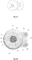
Fig. 2C illustrates a top view and a cross sectional view of an example of a removable magnet assembly according to an embodiment of the invention. -
Fig. 2D illustrates a further top view and cross sectional view of a further example of the invention. -
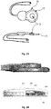
Fig. 3A illustrates a perspective view of an example of cochlear implant with its magnet removed with a tool according to an embodiment of the invention. -
Fig. 3B illustrates a detailed perspective view of an example of cochlear implant with its magnet removed from its place according to an embodiment of the invention. -
Fig. 3C illustrates various stages of interaction between removal tool and magnet. -
Fig. 4 shows an exploded view of a magnet and magnet holder according to the invention. -
Fig. 5A is a plane view of a further embodiment of the invention. -
Fig. 5B is a plane view of yet another embodiment of the invention. -
Fig. 6A discloses a further embodiment of the invention in two plane views. -
Fig. 6B is a cross sectional view of the embodiment offig. 6A . -
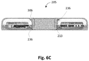
Fig. 6C is a cross sectional view of the housing belonging to the embodiment offig, 6A and 6B . - Embodiments of the present invention retain a cochlear implant magnet securely positioned in the center of the cochlear implant housing while maintaining a very compact structure. At the same time, the electronics and the coil of the cochlear implant are hermetically isolated. An interface between the magnet assembly and the cochlear housing has been designed to provide excellent alignment of the magnet within the cochlear implant housing. The interface also enables easy and safe removal of the magnet when needed.
-
Figs. 2A-B illustrate an example of a cochlear implant with asubcutaneous housing 201 which has a compact structure andhouses electronics 202 and one ormore coils 203 for receiving and transmitting information and energy. Also feedthroughs (not shown) for connecting electrodes to the subcutaneous housing are part of the construction. Such electrodes can stimulate or measure electrophysiological signals in the patient's body. In other situations, the electrical connections to/from the inside of the housing may also or alternatively connect an electromechanical actuator such as vibrator for bone conduction or for stimulating the middle ear. - A
magnet 205 is installed removably in acentral cavity 230 ofhousing 201. Thecentral cavity 230 is in the center of the annulus formed by thehousing 201. Themagnet 205 creates a magnetic field that holds and centers an external device that includes one or more coils. The external device can thus communicate with the implanted cochlear implant or supply energy to the cochlear implant. - The
subcutaneous housing 201 may include asilicone rim 206 to provide a soft and ergonomic shape that helps preserve surrounding patient tissues when the cochlear implant is surgically implanted. The continuation of thesilicone rim 206 forms twoflaps 207.Flaps 207 each include a reinforcingring 208. Therings 208 can be made of biocompatible material such as titanium, PEEK or PEKK, in order to allow the implant to be fixed onto the temporal bone of a patient. The implant can be fastened to the skull bone with screws that pass through rings 208. - An area between reinforcing
rings 208 forms ajunction 220. Thejunction 220 can house or accommodate electrodes passing to feedthroughs from an external device. - The
main housing 201 is composed of a main body having a U-shaped cross sectional profile, referred to as U-shapedmain body 210. The U-shapedmain body 210 forms a cavity which hermetically accommodateselectronics 202 andcoil 203. The U-shapedmain body 210 can be made of biocompatible ceramic such as zirconia toughened alumina, high purity alumina, or pure zirconia. A stampedtitanium cover 211 is attached to the rim of the U-shapedmain body 210 by laser welding to form a hermetically sealed cavity. -
Magnet 205 is guided directly by U-shapedmain body 210 through a precisely sized diameter ofcentral cavity 230. The precise sizing of the diameter reduces free movement of themagnet 205 to only a rotation aboutremoval axis 212 or a translation in the direction of theremoval axis 212. No pitching or tilting ofmagnet 205 relative tohousing 201 is possible when the magnet is fully installed in thecentral cavity 230.Removal axis 212 passes through the center of thecentral cavity 230 and is perpendicular to the plane of the top surface ofmain body 210. - The
magnet 205 is preferably biocompatible. Thus, themagnet 205 may be constructed as amagnetic core 240 surrounded by abiocompatible housing 245. Thebiocompatible housing 245 thus forms the outer surface of themagnet 205 and may be made of titanium. - As illustrated in
Fig. 2C , the body ofmagnet 205 is radially symmetrical except for a portion at thetop surface 223 of themagnet 205. The top of themagnet 205 has anouter edge 218 which is radially surpassed by raisedribs 214 andabutments 215.Fig. 2C illustrates an example with threeribs 214 and threeabutments 215. -
Abutments 215 extend radially farther out beyond the edge of theribs 214. Theabutments 215 prevent themagnet 205 from passing completely through thecentral cavity 230 of thehousing 201, and in case of shock or impact directly on theremovable magnet 205, energy will be dissipated to thehousing 201 and will not impact the patient's temporal bone by thesmall surface 216 of theremovable magnet 205, but by theentire surface 217 of theimplant housing 212. - While
abutments 215 are in contact with the rim of thecentral cavity 230, theribs 214 are sized smaller than theabutments 215, so there is agap 306 between the edge ofribs 214 and the rim of the central cavity. Thisgap 306 allows the insertion of atool 303 to remove themagnet 205 as described below. Theribs 214 have asmooth transition 219 from theedge 218, facilitating the rotation oftool 303 after it is inserted. -
Magnet 205 includes asilicone ring 213 that is calibrated to withstand a force induced by RMI of up to 3T. Thesilicone ring 213 is placed in aradial groove 235 in the body ofmagnet 205. When themagnet 205 is inserted intocentral cavity 230, thesilicone ring 213 exerts force on both themagnet 205 and the inner walls ofcentral cavity 230 to hold themagnet 205 securely in place. As shown inFig. 2B , the side profile ofcentral cavity 230 has aledge 236 under whichsilicone ring 213 is engaged, thus biasing themagnet 205 against removal from thecentral cavity 230. - As shown in
Fig. 3A ,magnet 205 can be removed from the housing 302 withremoval tool 303. It may sometimes be necessary to remove themagnet 205, such as when a very high level of MRI (e.g., above 3T) is needed. - When the magnet is to be removed, a surgeon can make an incision above the magnet and lift the skin away from the magnet area. A
tool 303 can then be inserted through the incision and used to remove themagnet 205. As shown in detail inFig. 3B , thetool 303 has itsown magnet 304 placed at the proximal edge of the tool in order to automatically align thetool 303 on themagnet 205. As seen inFig. 3C the surgeon has to insert the number ofblades 305 at the proximal edge of thetool 303 into thegaps 306 defined between the outer edge of themagnet 218 and the rim of thecentral cavity 230. This position is seen in the middle part ofFig. 3C . Then, thetool 303 is turned counter-clockwise enough to lock theblades 305 under theribs 214 via hooks 310. This final position is shown in the left hand view ofFig. 3C . In this position a secure engagement between tool and magnet has been established, and the tool and magnet may be lifted out ofcavity 230 without further ado. As the surgeon exerts force on the magnet, the supporting force from thesilicone ring 213, which holds themagnet 205 in thecavity 230, is overcome and the magnet is removed. The embeddedmagnet 304 holds themagnet 205 at the proximal edge of thetool 303 even after themagnet 205 is removed. Themagnet 205 can be easily removed from the tool by hand if need be, and be dealt with in the usual flow of contaminated elements of the hospital. - A new
sterile magnet 205 may be put in place by hand, without using a tool. It is preferable to rinse and dry thecentral cavity 230 before installing thenew magnet 205. As the surgeon presses thenew magnet 205 intocavity 230, compression strength of thesilicone ring 213 on thenew magnet 205 is overcome, and themagnet 205 slides securely into its correct position. -
Fig. 4 discloses an exploded view of the magnet and its enclosure. The enclosure comprises abiocompatible housing 245 shaped as a bucket with an outwardly directed upper rim comprising theouter edge 218, raisedribs 214 andabutments 215. Alid 246 is provided and secured to thebiocompatible housing 245 in atop recess 442, and inFig. 2D a weld line 243 is indicated for the fusing oflid 246 andbiocompatible housing 245. Other ways of fusing the lid to the housing could be used such as gluing or brazing. The various raisedribs 214 andabutments 215 are in the disclosed embodiment made as part of thehousing 245, but the skilled person would know, that there are many other options, such as providing these structural details as part of the lid. -
Figs. 5A and 5B discloses embodiments with two or fourabutments 215 respectively dispersed evenly around the circumference of themagnet 205 and a commensurate number ofribs 214. - In
Fig. 6A , B and C a further embodiment is shown wherein thesilicone ring 213 is provided as part of the implant, and themagnet 205 simply comprises thegroove 235. When the magnet is lifted out of the implant thesilicone ring 213 stays with the implant. This is advantageus from a hygienic point of view, as the intersection between silicone ring and magnet groove will not lend itself as a hiding place for infecting agents during or after autoclaving.List of elements: Number Element 12 coil 13 magnet 14 silicone part 101 hermetic housing 103 coil 104 fixed magnet 105 ceramic 106 titanium 201 subcutaneous housing 202 electronics 203 coil(s) 204 feedthroughs 205 magnet 206 silicone rim 207 flaps 208 ring 209 axis 210 U-shaped main body 211 stamped titanium cover 212 removal axis 213 silicone ring 214 rib 215 abutment 216 bottom surface of magnet 217 surface of housing 218 outer edge of magnet top 219 transistion 220 junction 223 top surface of magnet 230 central cavity 235 groove 236 ledge 240 magnetic core 242 top recess 243 weldline 245 biocompatible housing 246 lid 303 removal tool 304 magnet in tool 305 blade 306 gap(s) 310 hook 503 magnet 504 silicone molding 507 silicone lips 508 slots
Claims (12)
- A cochlear implant system, comprising:a subcutaneous housing (201) containing electronics (202) for at least stimulation or collection of data and at least one antenna (203) for communicating with an external device, the subcutaneous housing includinga main body (210) having a U-shaped radial cross-section,a bottom cover (211) secured to the main body (210), forming a hollow cavity bounded by an inner surface of the main body and the bottom cover, anda central cavity (230) in a center of the subcutaneous housing (201) formed by a portion of an outer surface of the main body, characterized in thatthe central cavity (230) comprises a a ledge (236);a magnet (205) removably inserted into said central cavity (230) includesa cylindrical body with a central axis, the central axis aligned with a removal axis (212) of the central cavity (230),a groove (235) extending circumferentially around the cylindrical body, anda top surface (223), the top surface includingan outer edge,a plurality of ribs (214) extending radially farther than the outer edge, anda plurality of abutments (215) extending radially farther than the ribs (214); anda compressive ring seated in at least one of the groove (235) of the cylindrical body or in the ledge (236) in the central cavity (230);, whereinthe compressive ring (213) engages the groove (235) and below the ledge (236) when the magnet is inserted into the central cavity (230) and biases the magnet against removal from the central cavity (230).
- The cochlear implant system according to claim 1, further comprising: a silicone rim (206) surrounding the body and tapering radially outward.
- The cochlear implant system according to claim 2, wherein
the silicone rim (206) includes two flaps (207) extending outward, each flap including a support ring (208) configured to accept a bone anchoring screw. - The cochlear implant system according to claim 3, further comprising:a junction area (220) formed as a part of the silicone rim (206) between the two flaps (207), the junction area (220) accommodating electrodes passing to external transducers such as cochlear, ear nerve or brain stem electrodes, or cochlear vibrators.
- The cochlear implant system according to claim 1, wherein
the bottom cover is a stamped titanium cover (211). - The cochlear implant system according to claim 5, wherein
the stamped titanium cover (211) includes a plurality of feedthroughs. - The cochlear implant system according to claim 1, wherein
the main body (210) is made of a biocompatible ceramic material. - The cochlear implant system according to claim 7, wherein the biocompatible material includes one ofzirconia toughened alumina,high purity alumina, andpure zirconia.
- The cochlear implant system according to claim 1, wherein
the top surface (223) of the magnet includes two or more ribs (214) and equally many abutments (215) equally spaced around the outer circumference of the outer edge of the top surface (223),
the abutments (215) are in contact with a rim of the central cavity (230) when the magnet is fully inserted into the central cavity (230), and
the ribs (214) are not in contact with the rim of the central cavity (230). - The cochlear implant system according to claim 9, wherein
each rib (214) has a smoothly tapered edge connected to the outer edge of the top surface, and
a void is bounded by the outer edge of the top surface and the rim of the central cavity (230). - The cochlear implant system according to claim 10, further comprising:a tool (303) for removing the magnet (205) from the central cavity (230), the tool (303) includinga handle portion,a second magnet (304) installed on a first end of the handle portion,blades (305) corresponding to the ribs (214) extending from the first end parallel to a central axis of the handle portion, each blade (305) terminating with a hook, whereineach blade (305) is insertable in said void,each hook engages under a respective rib (214) when the handle portion is rotated after insertion of the blades (305), andthe second magnet (304) attracts the magnet (205) in the central cavity (230) when the hooks engage under the ribs (214).
- The cochlear implant system according to claim 1, wherein
the magnet (205) includesan outer casing (245) made of a biocompatible material, anda magnetic core (240).
Priority Applications (5)
| Application Number | Priority Date | Filing Date | Title |
|---|---|---|---|
| EP13186200.5A EP2853287B1 (en) | 2013-09-26 | 2013-09-26 | Implantable device with removable magnet |
| DK13186200.5T DK2853287T3 (en) | 2013-09-26 | 2013-09-26 | IMPLANTABLE DEVICE WITH REMOVABLE MAGNET |
| US14/468,690 US9656065B2 (en) | 2013-09-26 | 2014-08-26 | Implantable device with removable magnet |
| AU2014233578A AU2014233578B2 (en) | 2013-09-26 | 2014-09-24 | Implantable Device with Removable Magnet |
| CN201410505379.1A CN104511094B (en) | 2013-09-26 | 2014-09-26 | Implantable device with detachable magnet |
Applications Claiming Priority (1)
| Application Number | Priority Date | Filing Date | Title |
|---|---|---|---|
| EP13186200.5A EP2853287B1 (en) | 2013-09-26 | 2013-09-26 | Implantable device with removable magnet |
Publications (2)
| Publication Number | Publication Date |
|---|---|
| EP2853287A1 EP2853287A1 (en) | 2015-04-01 |
| EP2853287B1 true EP2853287B1 (en) | 2017-10-25 |
Family
ID=49230656
Family Applications (1)
| Application Number | Title | Priority Date | Filing Date |
|---|---|---|---|
| EP13186200.5A Active EP2853287B1 (en) | 2013-09-26 | 2013-09-26 | Implantable device with removable magnet |
Country Status (5)
| Country | Link |
|---|---|
| US (1) | US9656065B2 (en) |
| EP (1) | EP2853287B1 (en) |
| CN (1) | CN104511094B (en) |
| AU (1) | AU2014233578B2 (en) |
| DK (1) | DK2853287T3 (en) |
Families Citing this family (45)
| Publication number | Priority date | Publication date | Assignee | Title |
|---|---|---|---|---|
| AU2003901696A0 (en) | 2003-04-09 | 2003-05-01 | Cochlear Limited | Implant magnet system |
| SE531177C2 (en) | 2007-05-24 | 2009-01-13 | Cochlear Ltd | Distance for implants |
| WO2013043176A1 (en) | 2011-09-22 | 2013-03-28 | Advanced Bionics Ag | Retention of a magnet in a cochlear implant |
| WO2015017898A1 (en) * | 2013-08-08 | 2015-02-12 | Clarus Technologies Pty Ltd | Bionic muscle |
| US9839777B2 (en) | 2013-08-14 | 2017-12-12 | Syntilla Medical LLC | Implantable neurostimulation lead for head pain |
| US9427566B2 (en) | 2013-08-14 | 2016-08-30 | Syntilla Medical LLC | Implantable neurostimulation lead for head pain |
| US9042991B2 (en) | 2013-08-14 | 2015-05-26 | Syntilla Medical LLC | Implantable head mounted neurostimulation system for head pain |
| US9498635B2 (en) | 2013-10-16 | 2016-11-22 | Syntilla Medical LLC | Implantable head located radiofrequency coupled neurostimulation system for head pain |
| US10960215B2 (en) | 2013-10-23 | 2021-03-30 | Nuxcel, Inc. | Low profile head-located neurostimulator and method of fabrication |
| US12569683B2 (en) | 2013-10-23 | 2026-03-10 | Shiratronics, Inc. | Implantable head located radiofrequency coupled neurostimulation system for head pain |
| US10258805B2 (en) | 2013-10-23 | 2019-04-16 | Syntilla Medical, Llc | Surgical method for implantable head mounted neurostimulation system for head pain |
| US10091594B2 (en) | 2014-07-29 | 2018-10-02 | Cochlear Limited | Bone conduction magnetic retention system |
| WO2016190886A1 (en) | 2015-05-28 | 2016-12-01 | Advanced Bionics Ag | Cochlear implants having mri-compatible magnet apparatus and associated methods |
| US10130807B2 (en) * | 2015-06-12 | 2018-11-20 | Cochlear Limited | Magnet management MRI compatibility |
| US20160381473A1 (en) | 2015-06-26 | 2016-12-29 | Johan Gustafsson | Magnetic retention device |
| WO2017027046A1 (en) * | 2015-08-13 | 2017-02-16 | Advanced Bionics Ag | Cochlear implants having a lateral magnet insertion and removal channel |
| US20170050027A1 (en) | 2015-08-18 | 2017-02-23 | Marcus ANDERSSON | Implantable Magnet Arrangements |
| US10758736B2 (en) | 2015-09-09 | 2020-09-01 | Med-El Elektromedizinische Geraete Gmbh | Fixation of a removable magnet or a similar element in an elastic implant material |
| US10917730B2 (en) | 2015-09-14 | 2021-02-09 | Cochlear Limited | Retention magnet system for medical device |
| US10806936B2 (en) | 2015-11-20 | 2020-10-20 | Advanced Bionics Ag | Cochlear implants and magnets for use with same |
| WO2017105510A1 (en) | 2015-12-18 | 2017-06-22 | Advanced Bionics Ag | Cochlear implants having mri-compatible magnet apparatus and associated methods |
| WO2017105511A1 (en) | 2015-12-18 | 2017-06-22 | Advanced Bionics Ag | Cochlear implants having mri-compatible magnet apparatus |
| US9717917B2 (en) | 2016-01-06 | 2017-08-01 | Syntilla Medical LLC | Charging system incorporating independent charging and communication with multiple implanted devices |
| AU2017241456B2 (en) * | 2016-03-29 | 2019-07-11 | Med-El Elektromedizinische Geraete Gmbh | Cochlear implant with clippable magnet |
| US10576276B2 (en) | 2016-04-29 | 2020-03-03 | Cochlear Limited | Implanted magnet management in the face of external magnetic fields |
| US10104482B2 (en) * | 2016-05-27 | 2018-10-16 | Cochlear Limited | Magnet positioning in an external device |
| US10646718B2 (en) | 2016-11-15 | 2020-05-12 | Advanced Bionics Ag | Cochlear implants and magnets for use with same |
| US10674287B2 (en) | 2016-11-23 | 2020-06-02 | Cochlear Limited | Magnet placement and antenna placement of an implant |
| US11595768B2 (en) | 2016-12-02 | 2023-02-28 | Cochlear Limited | Retention force increasing components |
| US11850417B2 (en) * | 2016-12-15 | 2023-12-26 | Cochlear Limited | Feedthrough placement |
| WO2018190813A1 (en) | 2017-04-11 | 2018-10-18 | Advanced Bionics Ag | Cochlear implants with retrofit magnets |
| CN110545880B (en) * | 2017-04-25 | 2023-09-01 | 领先仿生公司 | Cochlear implants with impact-resistant MRI-compatible magnet devices |
| US11287495B2 (en) | 2017-05-22 | 2022-03-29 | Advanced Bionics Ag | Methods and apparatus for use with cochlear implants having magnet apparatus with magnetic material particles |
| US10646712B2 (en) | 2017-09-13 | 2020-05-12 | Advanced Bionics Ag | Cochlear implants having MRI-compatible magnet apparatus |
| US20200324108A1 (en) * | 2017-10-10 | 2020-10-15 | Cochlear Limited | Neural stimulator with flying lead electrode |
| CN111344041B (en) | 2017-10-26 | 2024-11-26 | 领先仿生公司 | Headgear and implantable cochlear stimulation system including the same |
| CN112118888B (en) | 2018-02-15 | 2024-10-22 | 领先仿生公司 | Head-mounted device and implantable cochlear stimulation system including the same |
| CA3094526C (en) * | 2018-03-23 | 2025-04-01 | The Alfred E. Mann Foundation For Scientific Research | Skin patches for sensing or affecting a body parameter |
| CN108969194B (en) * | 2018-08-09 | 2024-04-09 | 浙江诺尔康神经电子科技股份有限公司 | Magnet tool in artificial cochlea |
| CN111663283B (en) * | 2019-03-07 | 2023-01-24 | 青岛海尔智能技术研发有限公司 | Disassembly method of washing machine pulsator assembly and washing machine |
| WO2021059163A1 (en) | 2019-09-27 | 2021-04-01 | Cochlear Limited | Multipole magnet for medical implant system |
| EP4126207B1 (en) | 2020-03-31 | 2026-03-11 | Advanced Bionics AG | Headpieces and implantable cochlear stimulation systems including the same |
| AU2021225130B2 (en) | 2020-09-09 | 2024-01-18 | Med-El Elektromedizinische Geraete Gmbh | Holding Magnets and Magnet System for Implantable Systems Optimized for MRI |
| US12440668B2 (en) | 2021-10-12 | 2025-10-14 | Advanced Bionics Ag | Cochlear implants having MRI-compatible magnet apparatus and associated systems and methods |
| DE102022103439A1 (en) * | 2022-02-14 | 2023-08-17 | Cortec Gmbh | Impact protection for hermetically sealed implant |
Family Cites Families (5)
| Publication number | Priority date | Publication date | Assignee | Title |
|---|---|---|---|---|
| CA2679413C (en) * | 2007-03-07 | 2014-05-06 | Med-El Elektromedizinische Geraete Gmbh | Implantable device with removable magnet |
| WO2009048999A1 (en) * | 2007-10-12 | 2009-04-16 | Med-El Elektromedizinische Geraete Gmbh | Implant magnet insertion and removal tools |
| FR2931076B1 (en) | 2008-05-15 | 2010-06-25 | Neurelec | IMPLANTABLE SUB-CUTANE DEVICE |
| WO2013043176A1 (en) * | 2011-09-22 | 2013-03-28 | Advanced Bionics Ag | Retention of a magnet in a cochlear implant |
| CN103907362B (en) * | 2011-10-27 | 2017-08-29 | Med-El电气医疗器械有限公司 | The fixation and removal of hearing assistance system external coil |
-
2013
- 2013-09-26 DK DK13186200.5T patent/DK2853287T3/en active
- 2013-09-26 EP EP13186200.5A patent/EP2853287B1/en active Active
-
2014
- 2014-08-26 US US14/468,690 patent/US9656065B2/en active Active
- 2014-09-24 AU AU2014233578A patent/AU2014233578B2/en not_active Ceased
- 2014-09-26 CN CN201410505379.1A patent/CN104511094B/en active Active
Non-Patent Citations (1)
| Title |
|---|
| None * |
Also Published As
| Publication number | Publication date |
|---|---|
| US20150087892A1 (en) | 2015-03-26 |
| CN104511094B (en) | 2018-09-04 |
| EP2853287A1 (en) | 2015-04-01 |
| AU2014233578B2 (en) | 2018-09-20 |
| AU2014233578A1 (en) | 2015-04-09 |
| DK2853287T3 (en) | 2018-01-15 |
| CN104511094A (en) | 2015-04-15 |
| US9656065B2 (en) | 2017-05-23 |
Similar Documents
| Publication | Publication Date | Title |
|---|---|---|
| US9656065B2 (en) | Implantable device with removable magnet | |
| KR101450932B1 (en) | Implantable device with removable magnet | |
| AU2021200038B2 (en) | Fixation of a Removable Magnet or a Similar Element in an Elastic Implant Material | |
| AU2011242708B2 (en) | MRI-safe disk magnet for implants | |
| US20190022380A1 (en) | Implant magnet system | |
| AU2017241456B2 (en) | Cochlear implant with clippable magnet | |
| US20130096366A1 (en) | Implantable medical device | |
| RU198574U1 (en) | Cochlear implant magnet on ball elements |
Legal Events
| Date | Code | Title | Description |
|---|---|---|---|
| PUAI | Public reference made under article 153(3) epc to a published international application that has entered the european phase |
Free format text: ORIGINAL CODE: 0009012 |
|
| 17P | Request for examination filed |
Effective date: 20130926 |
|
| AK | Designated contracting states |
Kind code of ref document: A1 Designated state(s): AL AT BE BG CH CY CZ DE DK EE ES FI FR GB GR HR HU IE IS IT LI LT LU LV MC MK MT NL NO PL PT RO RS SE SI SK SM TR |
|
| AX | Request for extension of the european patent |
Extension state: BA ME |
|
| R17P | Request for examination filed (corrected) |
Effective date: 20151001 |
|
| RBV | Designated contracting states (corrected) |
Designated state(s): AL AT BE BG CH CY CZ DE DK EE ES FI FR GB GR HR HU IE IS IT LI LT LU LV MC MK MT NL NO PL PT RO RS SE SI SK SM TR |
|
| GRAP | Despatch of communication of intention to grant a patent |
Free format text: ORIGINAL CODE: EPIDOSNIGR1 |
|
| INTG | Intention to grant announced |
Effective date: 20170504 |
|
| RIN1 | Information on inventor provided before grant (corrected) |
Inventor name: IBANEZ, HERVE Inventor name: TOURREL, GUILLAUME |
|
| GRAS | Grant fee paid |
Free format text: ORIGINAL CODE: EPIDOSNIGR3 |
|
| GRAA | (expected) grant |
Free format text: ORIGINAL CODE: 0009210 |
|
| AK | Designated contracting states |
Kind code of ref document: B1 Designated state(s): AL AT BE BG CH CY CZ DE DK EE ES FI FR GB GR HR HU IE IS IT LI LT LU LV MC MK MT NL NO PL PT RO RS SE SI SK SM TR |
|
| REG | Reference to a national code |
Ref country code: GB Ref legal event code: FG4D |
|
| REG | Reference to a national code |
Ref country code: CH Ref legal event code: EP |
|
| REG | Reference to a national code |
Ref country code: AT Ref legal event code: REF Ref document number: 939368 Country of ref document: AT Kind code of ref document: T Effective date: 20171115 |
|
| REG | Reference to a national code |
Ref country code: IE Ref legal event code: FG4D |
|
| REG | Reference to a national code |
Ref country code: DE Ref legal event code: R096 Ref document number: 602013028328 Country of ref document: DE |
|
| REG | Reference to a national code |
Ref country code: DK Ref legal event code: T3 Effective date: 20180111 |
|
| REG | Reference to a national code |
Ref country code: SE Ref legal event code: TRGR |
|
| REG | Reference to a national code |
Ref country code: NL Ref legal event code: MP Effective date: 20171025 |
|
| REG | Reference to a national code |
Ref country code: LT Ref legal event code: MG4D |
|
| PG25 | Lapsed in a contracting state [announced via postgrant information from national office to epo] |
Ref country code: NL Free format text: LAPSE BECAUSE OF FAILURE TO SUBMIT A TRANSLATION OF THE DESCRIPTION OR TO PAY THE FEE WITHIN THE PRESCRIBED TIME-LIMIT Effective date: 20171025 |
|
| PG25 | Lapsed in a contracting state [announced via postgrant information from national office to epo] |
Ref country code: ES Free format text: LAPSE BECAUSE OF FAILURE TO SUBMIT A TRANSLATION OF THE DESCRIPTION OR TO PAY THE FEE WITHIN THE PRESCRIBED TIME-LIMIT Effective date: 20171025 Ref country code: FI Free format text: LAPSE BECAUSE OF FAILURE TO SUBMIT A TRANSLATION OF THE DESCRIPTION OR TO PAY THE FEE WITHIN THE PRESCRIBED TIME-LIMIT Effective date: 20171025 Ref country code: LT Free format text: LAPSE BECAUSE OF FAILURE TO SUBMIT A TRANSLATION OF THE DESCRIPTION OR TO PAY THE FEE WITHIN THE PRESCRIBED TIME-LIMIT Effective date: 20171025 Ref country code: NO Free format text: LAPSE BECAUSE OF FAILURE TO SUBMIT A TRANSLATION OF THE DESCRIPTION OR TO PAY THE FEE WITHIN THE PRESCRIBED TIME-LIMIT Effective date: 20180125 |
|
| PG25 | Lapsed in a contracting state [announced via postgrant information from national office to epo] |
Ref country code: BG Free format text: LAPSE BECAUSE OF FAILURE TO SUBMIT A TRANSLATION OF THE DESCRIPTION OR TO PAY THE FEE WITHIN THE PRESCRIBED TIME-LIMIT Effective date: 20180125 Ref country code: LV Free format text: LAPSE BECAUSE OF FAILURE TO SUBMIT A TRANSLATION OF THE DESCRIPTION OR TO PAY THE FEE WITHIN THE PRESCRIBED TIME-LIMIT Effective date: 20171025 Ref country code: GR Free format text: LAPSE BECAUSE OF FAILURE TO SUBMIT A TRANSLATION OF THE DESCRIPTION OR TO PAY THE FEE WITHIN THE PRESCRIBED TIME-LIMIT Effective date: 20180126 Ref country code: IS Free format text: LAPSE BECAUSE OF FAILURE TO SUBMIT A TRANSLATION OF THE DESCRIPTION OR TO PAY THE FEE WITHIN THE PRESCRIBED TIME-LIMIT Effective date: 20180225 Ref country code: RS Free format text: LAPSE BECAUSE OF FAILURE TO SUBMIT A TRANSLATION OF THE DESCRIPTION OR TO PAY THE FEE WITHIN THE PRESCRIBED TIME-LIMIT Effective date: 20171025 Ref country code: HR Free format text: LAPSE BECAUSE OF FAILURE TO SUBMIT A TRANSLATION OF THE DESCRIPTION OR TO PAY THE FEE WITHIN THE PRESCRIBED TIME-LIMIT Effective date: 20171025 |
|
| REG | Reference to a national code |
Ref country code: DE Ref legal event code: R097 Ref document number: 602013028328 Country of ref document: DE |
|
| PG25 | Lapsed in a contracting state [announced via postgrant information from national office to epo] |
Ref country code: EE Free format text: LAPSE BECAUSE OF FAILURE TO SUBMIT A TRANSLATION OF THE DESCRIPTION OR TO PAY THE FEE WITHIN THE PRESCRIBED TIME-LIMIT Effective date: 20171025 Ref country code: SK Free format text: LAPSE BECAUSE OF FAILURE TO SUBMIT A TRANSLATION OF THE DESCRIPTION OR TO PAY THE FEE WITHIN THE PRESCRIBED TIME-LIMIT Effective date: 20171025 Ref country code: CZ Free format text: LAPSE BECAUSE OF FAILURE TO SUBMIT A TRANSLATION OF THE DESCRIPTION OR TO PAY THE FEE WITHIN THE PRESCRIBED TIME-LIMIT Effective date: 20171025 Ref country code: CY Free format text: LAPSE BECAUSE OF FAILURE TO SUBMIT A TRANSLATION OF THE DESCRIPTION OR TO PAY THE FEE WITHIN THE PRESCRIBED TIME-LIMIT Effective date: 20171025 |
|
| REG | Reference to a national code |
Ref country code: FR Ref legal event code: PLFP Year of fee payment: 6 |
|
| PG25 | Lapsed in a contracting state [announced via postgrant information from national office to epo] |
Ref country code: PL Free format text: LAPSE BECAUSE OF FAILURE TO SUBMIT A TRANSLATION OF THE DESCRIPTION OR TO PAY THE FEE WITHIN THE PRESCRIBED TIME-LIMIT Effective date: 20171025 Ref country code: RO Free format text: LAPSE BECAUSE OF FAILURE TO SUBMIT A TRANSLATION OF THE DESCRIPTION OR TO PAY THE FEE WITHIN THE PRESCRIBED TIME-LIMIT Effective date: 20171025 Ref country code: IT Free format text: LAPSE BECAUSE OF FAILURE TO SUBMIT A TRANSLATION OF THE DESCRIPTION OR TO PAY THE FEE WITHIN THE PRESCRIBED TIME-LIMIT Effective date: 20171025 Ref country code: SM Free format text: LAPSE BECAUSE OF FAILURE TO SUBMIT A TRANSLATION OF THE DESCRIPTION OR TO PAY THE FEE WITHIN THE PRESCRIBED TIME-LIMIT Effective date: 20171025 |
|
| PLBE | No opposition filed within time limit |
Free format text: ORIGINAL CODE: 0009261 |
|
| STAA | Information on the status of an ep patent application or granted ep patent |
Free format text: STATUS: NO OPPOSITION FILED WITHIN TIME LIMIT |
|
| 26N | No opposition filed |
Effective date: 20180726 |
|
| PG25 | Lapsed in a contracting state [announced via postgrant information from national office to epo] |
Ref country code: SI Free format text: LAPSE BECAUSE OF FAILURE TO SUBMIT A TRANSLATION OF THE DESCRIPTION OR TO PAY THE FEE WITHIN THE PRESCRIBED TIME-LIMIT Effective date: 20171025 |
|
| PG25 | Lapsed in a contracting state [announced via postgrant information from national office to epo] |
Ref country code: MC Free format text: LAPSE BECAUSE OF FAILURE TO SUBMIT A TRANSLATION OF THE DESCRIPTION OR TO PAY THE FEE WITHIN THE PRESCRIBED TIME-LIMIT Effective date: 20171025 |
|
| REG | Reference to a national code |
Ref country code: BE Ref legal event code: MM Effective date: 20180930 |
|
| REG | Reference to a national code |
Ref country code: IE Ref legal event code: MM4A |
|
| PG25 | Lapsed in a contracting state [announced via postgrant information from national office to epo] |
Ref country code: LU Free format text: LAPSE BECAUSE OF NON-PAYMENT OF DUE FEES Effective date: 20180926 |
|
| PG25 | Lapsed in a contracting state [announced via postgrant information from national office to epo] |
Ref country code: IE Free format text: LAPSE BECAUSE OF NON-PAYMENT OF DUE FEES Effective date: 20180926 |
|
| PG25 | Lapsed in a contracting state [announced via postgrant information from national office to epo] |
Ref country code: BE Free format text: LAPSE BECAUSE OF NON-PAYMENT OF DUE FEES Effective date: 20180930 |
|
| PG25 | Lapsed in a contracting state [announced via postgrant information from national office to epo] |
Ref country code: MT Free format text: LAPSE BECAUSE OF NON-PAYMENT OF DUE FEES Effective date: 20180926 |
|
| REG | Reference to a national code |
Ref country code: AT Ref legal event code: UEP Ref document number: 939368 Country of ref document: AT Kind code of ref document: T Effective date: 20171025 |
|
| PG25 | Lapsed in a contracting state [announced via postgrant information from national office to epo] |
Ref country code: TR Free format text: LAPSE BECAUSE OF FAILURE TO SUBMIT A TRANSLATION OF THE DESCRIPTION OR TO PAY THE FEE WITHIN THE PRESCRIBED TIME-LIMIT Effective date: 20171025 |
|
| PG25 | Lapsed in a contracting state [announced via postgrant information from national office to epo] |
Ref country code: HU Free format text: LAPSE BECAUSE OF FAILURE TO SUBMIT A TRANSLATION OF THE DESCRIPTION OR TO PAY THE FEE WITHIN THE PRESCRIBED TIME-LIMIT; INVALID AB INITIO Effective date: 20130926 Ref country code: PT Free format text: LAPSE BECAUSE OF FAILURE TO SUBMIT A TRANSLATION OF THE DESCRIPTION OR TO PAY THE FEE WITHIN THE PRESCRIBED TIME-LIMIT Effective date: 20171025 |
|
| PG25 | Lapsed in a contracting state [announced via postgrant information from national office to epo] |
Ref country code: MK Free format text: LAPSE BECAUSE OF NON-PAYMENT OF DUE FEES Effective date: 20171025 |
|
| PG25 | Lapsed in a contracting state [announced via postgrant information from national office to epo] |
Ref country code: AL Free format text: LAPSE BECAUSE OF FAILURE TO SUBMIT A TRANSLATION OF THE DESCRIPTION OR TO PAY THE FEE WITHIN THE PRESCRIBED TIME-LIMIT Effective date: 20171025 |
|
| REG | Reference to a national code |
Ref country code: DE Ref legal event code: R081 Ref document number: 602013028328 Country of ref document: DE Owner name: COCHLEAR LIMITED, MACQUARIE UNIVERSITY, AU Free format text: FORMER OWNER: OTICON MEDICAL A/S, SMOERUM, DK |
|
| REG | Reference to a national code |
Ref country code: GB Ref legal event code: 732E Free format text: REGISTERED BETWEEN 20240718 AND 20240724 |
|
| PGFP | Annual fee paid to national office [announced via postgrant information from national office to epo] |
Ref country code: DK Payment date: 20240913 Year of fee payment: 12 |
|
| PGFP | Annual fee paid to national office [announced via postgrant information from national office to epo] |
Ref country code: GB Payment date: 20240815 Year of fee payment: 12 |
|
| REG | Reference to a national code |
Ref country code: AT Ref legal event code: PC Ref document number: 939368 Country of ref document: AT Kind code of ref document: T Owner name: COCHLEAR LIMITED, AU Effective date: 20240909 |
|
| PGFP | Annual fee paid to national office [announced via postgrant information from national office to epo] |
Ref country code: FR Payment date: 20240821 Year of fee payment: 12 |
|
| PGFP | Annual fee paid to national office [announced via postgrant information from national office to epo] |
Ref country code: SE Payment date: 20240828 Year of fee payment: 12 |
|
| REG | Reference to a national code |
Ref country code: CH Ref legal event code: U11 Free format text: ST27 STATUS EVENT CODE: U-0-0-U10-U11 (AS PROVIDED BY THE NATIONAL OFFICE) Effective date: 20260217 |
|
| PGFP | Annual fee paid to national office [announced via postgrant information from national office to epo] |
Ref country code: DE Payment date: 20260211 Year of fee payment: 13 |
|
| PGFP | Annual fee paid to national office [announced via postgrant information from national office to epo] |
Ref country code: AT Payment date: 20260225 Year of fee payment: 13 |
|
| REG | Reference to a national code |
Ref country code: DK Ref legal event code: EBP Effective date: 20250930 |
|
| PGFP | Annual fee paid to national office [announced via postgrant information from national office to epo] |
Ref country code: CH Payment date: 20260217 Year of fee payment: 13 |