CN111663283B - Disassembly method of washing machine pulsator assembly and washing machine - Google Patents
Disassembly method of washing machine pulsator assembly and washing machine Download PDFInfo
- Publication number
- CN111663283B CN111663283B CN201910172922.3A CN201910172922A CN111663283B CN 111663283 B CN111663283 B CN 111663283B CN 201910172922 A CN201910172922 A CN 201910172922A CN 111663283 B CN111663283 B CN 111663283B
- Authority
- CN
- China
- Prior art keywords
- engaging structure
- pulsator assembly
- tool
- dismounting
- clamping
- Prior art date
- Legal status (The legal status is an assumption and is not a legal conclusion. Google has not performed a legal analysis and makes no representation as to the accuracy of the status listed.)
- Active
Links
Images


Classifications
-
- D—TEXTILES; PAPER
- D06—TREATMENT OF TEXTILES OR THE LIKE; LAUNDERING; FLEXIBLE MATERIALS NOT OTHERWISE PROVIDED FOR
- D06F—LAUNDERING, DRYING, IRONING, PRESSING OR FOLDING TEXTILE ARTICLES
- D06F17/00—Washing machines having receptacles, stationary for washing purposes, wherein the washing action is effected solely by circulation or agitation of the washing liquid
- D06F17/06—Washing machines having receptacles, stationary for washing purposes, wherein the washing action is effected solely by circulation or agitation of the washing liquid by rotary impellers
-
- B—PERFORMING OPERATIONS; TRANSPORTING
- B25—HAND TOOLS; PORTABLE POWER-DRIVEN TOOLS; MANIPULATORS
- B25B—TOOLS OR BENCH DEVICES NOT OTHERWISE PROVIDED FOR, FOR FASTENING, CONNECTING, DISENGAGING OR HOLDING
- B25B27/00—Hand tools, specially adapted for fitting together or separating parts or objects whether or not involving some deformation, not otherwise provided for
- B25B27/14—Hand tools, specially adapted for fitting together or separating parts or objects whether or not involving some deformation, not otherwise provided for for assembling objects other than by press fit or detaching same
-
- D—TEXTILES; PAPER
- D06—TREATMENT OF TEXTILES OR THE LIKE; LAUNDERING; FLEXIBLE MATERIALS NOT OTHERWISE PROVIDED FOR
- D06F—LAUNDERING, DRYING, IRONING, PRESSING OR FOLDING TEXTILE ARTICLES
- D06F17/00—Washing machines having receptacles, stationary for washing purposes, wherein the washing action is effected solely by circulation or agitation of the washing liquid
- D06F17/06—Washing machines having receptacles, stationary for washing purposes, wherein the washing action is effected solely by circulation or agitation of the washing liquid by rotary impellers
- D06F17/10—Impellers
Landscapes
- Engineering & Computer Science (AREA)
- Textile Engineering (AREA)
- Mechanical Engineering (AREA)
- Main Body Construction Of Washing Machines And Laundry Dryers (AREA)
- Structures Of Non-Positive Displacement Pumps (AREA)
Abstract
本发明提供了一种洗衣机波轮组件的拆卸方法及洗衣机,波轮组件与输出轴卡合固定,在所述波轮组件上设有用于所述波轮组件轴向卡合定位的卡合结构,在所述输出轴上开设有与所述卡合结构相匹配的至少一个卡槽;所述拆卸方法为利用具有磁体的拆卸工具与卡合结构之间产生的磁力,使得所述卡合结构与卡槽脱离。在需要拆卸波轮组件时,只需要将拆卸工具靠近卡合结构就可,由于磁力的穿透性,可以在不对波轮组件的任何部件进行拆卸的情况下,实现对于卡合结构施加力,实现卡合固定的脱离,使得卡合结构的结构设置简单,使得拆卸操作简单,省力方便。在波轮组件拆卸后将拆卸工具移开后,磁力撤销,使得卡合结构复位,再将波轮组件安装到位。

The invention provides a washing machine pulsator assembly disassembly method and washing machine, the pulsator assembly is engaged and fixed with the output shaft, and the pulsator assembly is provided with an engaging structure for the axial engagement and positioning of the pulsator assembly , at least one slot matching the engaging structure is opened on the output shaft; the dismounting method is to use the magnetic force generated between the dismounting tool with a magnet and the engaging structure, so that the engaging structure Disengage from the card slot. When it is necessary to disassemble the pulsator assembly, it is only necessary to bring the disassembly tool close to the engaging structure. Due to the penetrability of the magnetic force, it is possible to apply force to the engaging structure without disassembling any part of the pulsator assembly. The detachment of the clamping and fixing is realized, so that the structural setting of the clamping structure is simple, and the dismounting operation is simple, labor-saving and convenient. After the removal tool is removed after the pulsator assembly is disassembled, the magnetic force is cancelled, so that the engaging structure is reset, and then the pulsator assembly is installed in place.
Description
技术领域technical field
本发明属于洗衣机技术领域,具体涉及一种洗衣机波轮组件的拆卸方法及洗衣机。The invention belongs to the technical field of washing machines, and in particular relates to a method for disassembling a wave wheel assembly of a washing machine and a washing machine.
背景技术Background technique
现有的洗衣机在使用一定的时间后,通常会在波轮下表面、内桶和外桶壁上的不可见位置留下一些污垢和细菌,不易清洗。长时间不清洗甚至会造成交叉感染、皮肤病等疾病。目前对于上述各部件的清洗,最可靠的办法是将各个部件拆卸下来后再进行清洗。但是由于现有的洗衣机的波轮和驱动部件的输出轴之间大都是通过螺栓固定连接的,波轮的拆卸和安装比较麻烦,不利于波轮的清洗;而且长期浸泡于水中的螺钉与波轮塑件结合粘结,也常会出现无法拆下来的问题。也有部分洗衣机的波轮采用可拆卸方式连接于输出轴,但是其可拆卸的结构过于复杂,依旧存在拆卸不便的问题。After the existing washing machine is used for a certain period of time, some dirt and bacteria will usually be left on the lower surface of the pulsator, the invisible positions on the walls of the inner tub and the outer tub, which is not easy to clean. If it is not cleaned for a long time, it may even cause cross-infection, skin diseases and other diseases. For the cleaning of above-mentioned each parts at present, the most reliable way is to clean after each part is disassembled. However, because the wave wheel of the existing washing machine and the output shaft of the driving part are mostly fixedly connected by bolts, the disassembly and installation of the wave wheel are troublesome, which is not conducive to the cleaning of the wave wheel; and the screws and wave wheels soaked in water for a long time Wheel-plastic parts are combined and bonded, and there are often problems that cannot be removed. There are also wave wheels of some washing machines that are detachably connected to the output shaft, but the detachable structure is too complicated, and there is still the problem of inconvenient disassembly.
发明内容Contents of the invention
本发明针对现有技术中存在的上述问题,提供一种洗衣机波轮组件的拆卸方法,以解决现有洗衣机存在着的波轮拆卸不便的问题,实现洗衣机波轮的快速拆卸。Aiming at the above problems in the prior art, the present invention provides a method for disassembling the pulsator assembly of a washing machine, so as to solve the problem of inconvenient disassembly of the pulsator in the existing washing machine and realize quick disassembly of the pulsator of the washing machine.
为达到上述技术目的,本发明采用以下技术方案实现:In order to achieve the above-mentioned technical purpose, the present invention adopts the following technical solutions to realize:
一种洗衣机波轮组件的拆卸方法,所述波轮组件与输出轴卡合固定,在所述波轮组件上设有用于所述波轮组件轴向卡合定位的卡合结构,在所述输出轴上开设有与所述卡合结构相匹配的至少一个卡槽;所述拆卸方法为利用具有磁体的拆卸工具与卡合结构之间产生的磁力,使得所述卡合结构与卡槽脱离。A method for dismounting a washing machine pulsator assembly, the pulsator assembly is engaged and fixed with an output shaft, and an engaging structure for the axial engagement and positioning of the pulsator assembly is provided on the pulsator assembly. The output shaft is provided with at least one slot matching the engaging structure; the dismounting method is to use the magnetic force generated between the dismounting tool with a magnet and the engaging structure to disengage the engaging structure from the engaging slot .
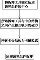
进一步的,所述拆卸方法具有下述步骤: A、将拆卸工具靠近所述卡合结构;Further, the disassembly method has the following steps: A. Bring the disassembly tool close to the engaging structure;
B、所述拆卸工具与卡合结构之间产生相互吸引的磁力,使得所述卡合结构与卡槽脱离;B. A magnetic force of mutual attraction is generated between the removal tool and the engaging structure, so that the engaging structure is disengaged from the engaging groove;
C、将所述波轮组件向所述衣物投入口方向移动、并拆卸。C. Move the pulsator assembly toward the clothes inlet and disassemble it.
进一步的,在步骤A之间还具有步骤A0,将所述拆卸工具从洗衣机衣物投入口伸入内桶,并靠近所述波轮组件。Further, there is also a step A0 between the steps A, which is to extend the removal tool from the laundry inlet of the washing machine into the inner tub and get close to the pulsator assembly.
进一步的,在步骤B之前还具有步骤B0,在拆卸工具靠近卡合结构的过程中,当所述拆卸工具与卡合结构之间的距离等于或小于两者之间的磁力感应范围时,所述拆卸工具与卡合结构之间产生相互吸引的磁力,使得所述拆卸工具与卡合结构具有相互靠近的移动趋势。Further, there is also a step B0 before step B, in the process of the removal tool approaching the engaging structure, when the distance between the removing tool and the engaging structure is equal to or less than the magnetic induction range between the two, the A magnetic force of mutual attraction is generated between the removal tool and the engaging structure, so that the removal tool and the engaging structure have a tendency to move closer to each other.
进一步的,在步骤B中,所述拆卸工具在磁力的作用下到达所述波轮组件的上端,所述卡合结构在磁力的作用下向拆卸工具的方向移动,使得卡合结构与卡槽之间的锁定解除。Further, in step B, the removal tool reaches the upper end of the pulsator assembly under the action of magnetic force, and the engaging structure moves toward the direction of the removal tool under the action of magnetic force, so that the engaging structure and the slot The lock between them is released.
进一步的,所述卡合结构包括用于提供推动力实现卡合结构与卡槽处于卡合状态的弹力件;所述拆卸工具到达所述波轮组件的上端后,所述拆卸工具与卡合结构之间产生的磁力大于所述弹力件提供的推动力。Further, the engaging structure includes an elastic member for providing a driving force to realize the engagement between the engaging structure and the slot; after the removal tool reaches the upper end of the pulsator assembly, the removal tool and the engaging The magnetic force generated between the structures is greater than the driving force provided by the elastic member.
进一步的,所述卡合结构包括与所述卡槽相匹配卡合的卡紧件、锁定所述卡紧件处于卡合状态的限定件,所述卡紧件相对于所述限定件可径向移动。Further, the engaging structure includes a clamping part that matches and engages with the clamping slot, and a limiting part that locks the clamping part in an engaged state, and the clamping part can be diametrically opposed to the limiting part. to move.
进一步的,所述限定件和/或卡紧件采用可被磁体吸附的金属材料。Further, the restricting member and/or the clamping member is made of a metal material that can be attracted by a magnet.
进一步的,所述拆卸工具包括磁体、用于固定所述磁体的磁体固定部、以及位于所述磁体固定部上部的手持部,所述手持部具有周向且向外伸出设置的多个手持筋。Further, the removal tool includes a magnet, a magnet fixing part for fixing the magnet, and a handle part located on the upper part of the magnet fixing part. ribs.
进一步的,在所述手持部的上端设有环形的拉手。Further, an annular handle is provided on the upper end of the handle.
进一步的,所述卡紧件为球形。Further, the clamping member is spherical.
基于上述的洗衣机波轮组件的拆卸方法,本发明还提供一种具有该拆卸方法的洗衣机,以解决现有洗衣机存在着的波轮拆卸不便的问题,实现洗衣机波轮的快速拆卸。Based on the above method for disassembling the pulsator assembly of the washing machine, the present invention also provides a washing machine with the disassembly method, so as to solve the problem of inconvenient disassembly of the pulsator existing in existing washing machines and realize quick disassembly of the pulsator of the washing machine.
一种洗衣机,采用上述的拆卸方法进行波轮组件的拆卸。A washing machine, using the above disassembly method to disassemble the pulsator assembly.
本发明提供的洗衣机波轮组件的拆卸方法,通过拆卸工具与卡合结构之间的磁力,来实现所述卡合结构与卡槽的脱离;在需要拆卸波轮组件时,只需要将拆卸工具靠近卡合结构就可,由于磁力的穿透性,可以在不对波轮组件的任何部件进行拆卸的情况下,实现对于卡合结构施加力,实现卡合固定的脱离,使得卡合结构的结构设置简单,使得拆卸操作简单,省力方便。在波轮组件拆卸后将拆卸工具移开后,磁力撤销,使得卡合结构复位,再将波轮组件安装到位。The method for disassembling the pulsator assembly of the washing machine provided by the present invention uses the magnetic force between the dismounting tool and the engaging structure to realize the detachment of the engaging structure from the slot; It only needs to be close to the locking structure. Due to the penetrability of the magnetic force, it is possible to apply force to the locking structure without disassembling any part of the pulsator assembly, and realize the disengagement of the locking structure, so that the structure of the locking structure The setting is simple, which makes the disassembly operation simple, labor-saving and convenient. After the removal tool is removed after the pulsator assembly is disassembled, the magnetic force is cancelled, so that the engaging structure is reset, and then the pulsator assembly is installed in place.
结合附图阅读本发明的具体实施方式后,本发明的其他特点和优点将变得更加清楚。Other characteristics and advantages of the present invention will become clearer after reading the detailed description of the present invention in conjunction with the accompanying drawings.
附图说明Description of drawings
图1为本发明所提出的洗衣机波轮组件的拆卸方法的一个实施例的流程图;Fig. 1 is the flowchart of an embodiment of the dismounting method of washing machine pulsator assembly proposed by the present invention;
图2为采用图1的方法拆卸波轮组件的一种洗衣机的一种结构示意图;Fig. 2 is a schematic structural view of a washing machine in which the pulsator assembly is disassembled by the method of Fig. 1;
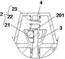
图3为图2中A-A向剖视放大结构示意图;Fig. 3 is a schematic diagram of the enlarged structure of the cross-sectional view of A-A in Fig. 2;
图4为图3中卡合结构处的放大结构示意图;Fig. 4 is a schematic diagram of an enlarged structure of the engaging structure in Fig. 3;
图5为图3中波轮组件拆卸后的部分结构放大示意图;Fig. 5 is an enlarged schematic diagram of part of the structure after disassembly of the pulsator assembly in Fig. 3;
图6为图3中输出轴的结构示意图;Fig. 6 is a schematic structural view of the output shaft in Fig. 3;
图7为图6中第二输出轴的放大结构示意图;Fig. 7 is a schematic diagram of the enlarged structure of the second output shaft in Fig. 6;
图8为图5中限定件的放大结构示意图;Fig. 8 is a schematic diagram of the enlarged structure of the limiting part in Fig. 5;
图9为图3中定位腔的放大结构示意图;Fig. 9 is a schematic diagram of an enlarged structure of the positioning cavity in Fig. 3;
图10为拆卸工具的结构示意图;Fig. 10 is a schematic structural view of the removal tool;
图11为图10的主视结构示意图;Fig. 11 is a schematic diagram of the front view of Fig. 10;
图12为图11的剖视结构示意图;Fig. 12 is a schematic cross-sectional structure diagram of Fig. 11;
图13为采用图1的流程图的洗衣机的第二种结构示意图;Fig. 13 is a second structural schematic view of the washing machine using the flowchart of Fig. 1;
图14为图13中卡合结构处的放大结构示意图;Fig. 14 is a schematic diagram of an enlarged structure of the engaging structure in Fig. 13;
图15为图13中输出轴的结构示意图;Fig. 15 is a schematic structural view of the output shaft in Fig. 13;
图16为采用图1的流程图的洗衣机的第三种结构示意图;Fig. 16 is a schematic diagram of a third structure of the washing machine using the flowchart of Fig. 1;
图17为图16中卡合结构处的放大结构示意图。FIG. 17 is an enlarged structural schematic diagram of the engaging structure in FIG. 16 .
具体实施方式Detailed ways
为使本发明实施例的目的、技术方案和优点更加清楚,下面将结合本发明实施例中的附图,对本发明实施例中的技术方案进行清楚、完整地描述。In order to make the purpose, technical solutions and advantages of the embodiments of the present invention more clear, the technical solutions in the embodiments of the present invention will be clearly and completely described below in conjunction with the drawings in the embodiments of the present invention.
在本发明的描述中,需要说明的是,术语 “内”、“上”、“下”、“左”、“右”等指示的方位或位置关系为基于附图所示的位置关系,以靠近波轮组件轴线的方向为“内”,波轮组件轴线的方向为 “外”。术语仅是为了便于描述本发明和简化描述,而不是指示或暗示所指的装置或元件必须具有特定的方位、以特定的方位构造和操作,因此不能理解为对本发明的限制。此外,术语“第一”、“第二”、“第三”仅用于描述目的,而不能理解为指示或暗示相对重要性;限定有“第一”、“第二”的特征可以明示或者隐含地包括一个或者更多个该特征。在本发明的描述中,“多个”的含义是两个或两个以上,除非另有明确具体的限定。In the description of the present invention, it should be noted that the orientation or positional relationship indicated by the terms "inner", "upper", "lower", "left", "right" etc. is based on the positional relationship shown in the drawings, and The direction close to the axis of the pulsator assembly is "inner", and the direction of the axis of the pulsator assembly is "outer". The terminology is only used to describe the present invention and simplify the description, but does not indicate or imply that the device or element referred to must have a specific orientation, be constructed and operated in a specific orientation, and thus should not be construed as limiting the present invention. In addition, the terms "first", "second", and "third" are used for descriptive purposes only, and cannot be interpreted as indicating or implying relative importance; features defined with "first" and "second" may express or One or more of these features are implicitly included. In the description of the present invention, "plurality" means two or more, unless otherwise specifically defined.
在本发明中,除非另有明确的规定和限定,术语“安装”、“相连”、“连接”、“固定”等术语应做广义理解,例如,可以是固定连接,也可以是可拆卸连接,或成一体;可以是机械连接,也可以是电连接;可以是直接相连,也可以通过中间媒介间接相连,可以是两个元件内部的连通或两个元件的相互作用关系。对于本领域的普通技术人员而言,可以根据具体情况理解上述术语在本发明中的具体含义。In the present invention, unless otherwise clearly specified and limited, terms such as "installation", "connection", "connection" and "fixation" should be understood in a broad sense, for example, it can be a fixed connection or a detachable connection , or integrated; it can be mechanically connected or electrically connected; it can be directly connected or indirectly connected through an intermediary, and it can be the internal communication of two components or the interaction relationship between two components. Those of ordinary skill in the art can understand the specific meanings of the above terms in the present invention according to specific situations.
参阅图1-图17,本发明所提出的洗衣机波轮组件的拆卸方法的一个实施例,为了便于说明参见采用1的方法拆卸波轮组件的第一种洗衣机,参见图2-图12所示,洗衣机包括与驱动电机连接的输出轴20、以及与输出轴20可拆卸连接的波轮组件10,波轮组件10可整体的与输出轴20卡合固定或者脱离分开,波轮组件10具有波轮1、以及用于波轮组件10轴向定位的卡合结构2,在输出轴20上开设有与卡合结构2相匹配的至少一个卡槽201。Referring to Fig. 1-Fig. 17, an embodiment of the dismantling method of the pulsator assembly of the washing machine proposed by the present invention, for the convenience of explanation, refer to the first washing machine using the
波轮组件10的拆卸方法为利用具有磁体的拆卸工具30与卡合结构2之间产生的磁力,使得卡合结构2与卡槽201脱离;通过拆卸工具30与卡合结构2之间的磁力,来实现所述卡合结构2与卡槽201的脱离;在需要拆卸波轮组件10时,只需要将拆卸工具30靠近卡合结构2就可,由于磁力的穿透性,可以在不对波轮组件10的任何部件进行拆卸的情况下,实现对于卡合结构2施加磁力,实现卡合固定2的脱离,使得卡合结构2的结构设置简单,使得拆卸操作简单,省力方便。在波轮组件10拆卸后将拆卸工具移开后,磁力撤销,使得卡合结构复位,再将波轮组件10安装到位。The disassembly method of the
本实施例中,对于卡合结构2的拆卸需要拆卸工具30,拆卸工具30具有磁体301,磁体301为磁铁或电磁铁,优选设置为磁铁。在需要拆卸波轮组件10时,将拆卸工具30放置到波轮组件10的卡合结构2的上方,或者说是放置到卡合结构2脱离的运动方向上,拆卸工具30靠近卡合结构2后,拆卸工具30和卡合结构2之间产生相吸引的磁力,吸引卡合结构2向靠近拆卸工具30的方向移动,也就是向上移动,使得卡合结构2与卡槽201脱离,也就是波轮组件10与输出轴20之间的轴向锁定解除;之后将波轮组件10向上移动与输出轴20脱离,实现波轮组件10的拆卸;之后将拆卸工具30拿开,使得卡合结构2复位。在波轮组件10清理干净后,将波轮组件10安装到输出轴20上,并使卡合结构2与卡槽201卡合。In this embodiment, disassembly of the engaging
对于波轮组件10的拆卸方法,具有下述步骤:For the dismounting method of
A0、将拆卸工具30从洗衣机的衣物投入口伸入内桶、并靠近波轮组件10。A0. Extend the
A、将拆卸工具30靠近卡合结构2,卡合结构2就设置在波轮组件10的中心处,也就是将拆卸工具30靠近波轮组件10的中心。A. Put the
B、拆卸工具30与卡合结构2之间产生相互吸引的磁力,使得卡合结构2与卡槽201脱离。B. A magnetic force of mutual attraction is generated between the
具体的,在拆卸工具30在磁力的作用下到达波轮组件10的上端,拆卸工具30不能在继续向靠近卡合结构2的方向移动,卡合结构2在磁力的作用下向拆卸工具30的方向移动,使得卡合结构2与卡槽201之间的锁定解除。Specifically, when the
C、将波轮组件30向所述衣物投入口方向移动、并拆卸。C. Move the
在步骤B之前还具有步骤B0,在拆卸工具30靠近卡合结构2的过程中,当拆卸工具30与卡合结构2之间的距离等于或小于两者之间的磁力感应范围时,拆卸工具30与卡合结构2之间产生相互吸引的磁力,使得拆卸工具30与卡合结构2具有相互靠近的移动趋势。There is also a step B0 before step B. In the process of the
参见图4所示,卡合结构2还包括为其提供推动力的弹力件23,卡合结构2与卡槽201卡合固定后,弹力件23给予卡合结构2向下的弹力,当拆卸工具30到达波轮组件10的上端时,拆卸工具30与卡合结构2之间产生的磁力大于弹力件23提供的推动力,使得卡合结构2向上移动。在考虑重力、摩擦力之后,拆卸工具30给予卡合结构2的磁性吸引力大于弹力件23给予的推动力和卡合结构2的重力之和,可以使得卡合结构2向上移动,当然还需要克服摩擦力。Referring to Figure 4, the engaging
参见图4所示,卡合结构2包括与卡槽201相匹配卡合的卡紧件21、限定卡紧件21的限定件22,卡紧件21相对于限定件22可径向移动,限定件22上开设有用于输出轴20穿过的第一通孔221。限定件22限定卡紧件21在轴向的位置,卡紧件21相对于限定件22可径向移动,实现卡紧件21与卡槽201的卡合和脱离;在拆卸波轮组件10时,卡紧件21向远离输出轴20的方向移动时,使得卡紧件21从卡槽201中退出,解除了卡合结构2与输出轴20之间的轴向卡合锁定。As shown in FIG. 4 , the engaging
波轮组件10还包括容纳卡紧件21和限定件22的定位腔3,定位腔3具有用于限定卡紧件21径向位移的定位腔壁31,卡紧件21与定位腔壁31接触,在定位腔3的底部开设有用于输出轴20伸入的第二通孔32,定位腔3的上端为敞口端。卡紧件21通过限定件22、定位腔壁31、以及卡槽201进行限位锁定,卡紧件21在径向上内侧接触卡槽201的槽底、外侧接触定位腔壁31,通过设置定位腔壁31在靠近定位腔3敞口端的方向上逐渐向外延伸,也就是定位腔壁31向上且向外延伸;在波轮组件10安装固定后,定位腔壁31与卡槽201的槽底之间的距离在向上方向上逐渐增加,也就是径向的距离在向上方向上逐渐增加。在波轮组件10拆卸时,拆卸工具30吸引卡合结构2向上移动,使得卡紧件21和限定件22向上移动,使得卡紧件21在径向上具有了向外移动的空间;卡紧件21向上移动,在到达卡槽201的上端时,由于定位腔壁31的倾斜设置,在卡紧件21向上移动后,定位腔壁31不再挡紧卡紧件21,使得卡紧件21向外移动,脱离卡槽201;之后将波轮组件10向上提起就可,此时卡合锁定已经解除。The
在其他实施例中,定位腔3可以不设置上端的敞口,而是在定位腔3上端开设有稍大的开口就可。In other embodiments, the
卡合结构2的卡紧件21和限定件22中至少一个为采用可被磁体301吸附的金属材料。当限定件22采用磁性金属材料、而卡紧件21不采用时,拆卸工具30给予限定件22向上的吸引力,在限定件22向上移动时,带动卡紧件21一起向上移动;在卡紧件21向上移动后就具有相对于限定件22可径向移动的空间;实现卡紧件21与卡槽201的卡合和脱离。At least one of the clamping
当卡紧件21采用磁性金属材料、而限定件22不采用时,拆卸工具30吸引卡紧件21向上移动,带动限定件22一起向上移动,之后卡紧件21具有了可径向移动的空间,在卡紧件21到达卡槽201的上端时,在径向向外移动,使得卡紧件21从卡槽201中退出,解除了卡合结构2与输出轴20之间的轴向卡合锁定。When the clamping
当卡紧件21和限定件22均采用磁性金属材料时,拆卸工具30吸引卡紧件21和限定件22均向上移动,由于还受到弹力件23给予限定件22向下的力,因而,卡紧件21和限定件22一起向上移动。When both the clamping
本实施例中,限定件22限定了卡紧件21在轴向的位置,卡紧件21可随限定件22在轴向上下移动;限定件22在卡合和脱离过程中,只具有轴向的上下移动,而卡紧件21还需要具有径向的移动;因而优选设置限定件22采用可被磁体301吸附的金属材料,卡紧件21采用不被磁体301吸附的材料。In this embodiment, the restricting
对于卡紧件21的结构设置,可以采用多中结构形式,球形、椭圆形、不规则形状;优选设置卡紧件21与定位腔壁31接触部采用弧面结构,有利于卡紧件21与定位腔壁31接触后的相对移动;更优选设置卡紧件21为球形,在卡紧件21安装时不用定位,并且由于移动、卡合、脱离卡槽时的移动平滑性。For the structural setting of the clamping
对于卡合结构2中卡紧件21的个数,可以设置一个或者多个;优选在容纳腔220内设置有三个卡紧件21,在输出轴20的周向上开设有三个卡槽201;通过设置三个轴向设置的卡紧件21,有利于增加波轮组件10卡合固定后的稳定性。As for the number of clamping
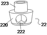
本实施例中,参见图8所示,限定件22包括用于容纳卡紧件21的容纳腔220,卡紧件21位于容纳腔220内,输出轴20穿过容纳腔220,容纳腔220和输出轴20共轴设置;在卡合结构2卡合在卡槽201后,卡槽201部分或全部位于容纳腔220内,卡紧件21的内侧与卡槽201的底部接触。在容纳腔220的中心开设有第一通孔221。在容纳腔220的腔壁上开设有用于卡紧件21伸出的开口222,开口222的直径小于卡紧件21的直径,卡紧件21伸出开口222并与定位腔壁31接触。通过设置限定件22具有容纳腔220,容纳腔220套装在输出轴20的外侧,使得限定件22只可以在上下移动;在限定件22在上下移动时,可以带动卡紧件21同步移动,并且卡紧件21可以具有径向的移动,实现卡紧件21与卡槽201的卡合和脱离。限定件22还包括沿第一通孔221向上延伸的第一限位沿223,第一限位沿223套装在输出轴20的外侧,弹力件23的下端套装在第一延伸223沿的外侧;通过设置第一限位沿223,一方面有利于保证限定件22在输出轴20上可以上下平稳的移动,保证限定件22移动的稳定性;另一方面有利于弹力件23与第一限位沿223的配合,更好的将弹力传递到限定件22上。In this embodiment, as shown in FIG. 8 , the limiting
参见图4所示,波轮组件10还包括与波轮1固定设置的外盖4,弹力件23位于外盖4和限定件22之间,弹力件23的下端与限定件22接触、上端与外盖4接触。外盖4包覆在定位腔3的外侧,将定位腔3密封,避免洗涤水进入定位腔3内;外盖4具有下口的容纳部,定位腔3位于容纳部内。在外盖4上设有向下延伸的第四延伸沿41,弹力件23的上端套装在第四延伸沿41的外侧。4, the
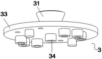
参见图5和图9所示,对于定位腔3的结构设置,定位腔3为定位腔壁31延伸围绕形成的腔体,定位腔壁31为锥形面;为了实现定位腔3的固定,定位腔3还设有径向向外延伸设置的定位固定部33,定位固定部33与波轮1固定连接,在第二通孔32的边缘设有向下延伸设置的第二定位沿34,通过设置第二定位沿34有利于定位腔3安装定位,以及固定后的稳定性。Referring to Fig. 5 and Fig. 9, for the structural setting of the
波轮组件10还包括与套装在输出轴20外侧的连接件5,在连接件5与输出轴20之间设有防止二者相对旋转的锁定件,连接件5位于波轮组件10的下部;The
输出轴20包括同轴固定设置的第一输出轴202和第二输出轴203,第一输出轴202的直径大于第二输出轴203的直径,在连接件5上开设有与第一输出轴202和第二输出轴203相匹配的台阶孔5;第二定位沿34位于台阶孔5内。The
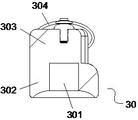
对于拆卸工具30的结构,可以采用单独的一个磁体,但为了操作方便,优选设置,拆卸工具30包括磁体301、用于固定磁体的磁体固定部302、以及位于磁体固定部302上部的手持部303,手持部303具有周向且向外伸出设置的多个手持筋。通过设置拆卸工具具有手持部303,有利于拿取拆卸工具方便,在将拆卸工具30放置到外盖4后,拆卸工具30与卡合结构2的限定件22之间具有较大的相互吸引力,在波轮组件10拆卸后,需要克服拆卸工具30与限定件22之间的磁性吸引力才能将拆卸工具30取走,因而设置手持部303,便于通过手部给予拆卸工具30较大的力。在手持部303的上端设有环形的拉手304,通过设置拉手304有利于对于拆卸工具30的取放。For the structure of the
参见图13-图15,为采用上述方法拆卸波轮组件的洗衣机的第二种结构,与第一种结构的主要区别在于:卡合结构处的具体结构不同,其他可以采用与第一种相同的结构。Referring to Figure 13-Figure 15, it is the second structure of the washing machine that uses the above method to disassemble the pulsator assembly. The main difference from the first structure is that the specific structure of the engaging structure is different, and the others can be the same as the first. Structure.
洗衣机包括与驱动电机连接的输出轴20、以及与输出轴20可拆卸连接的波轮组件10,波轮组件10可整体的与输出轴20卡合固定或者脱离分开,波轮组件10具有波轮1、以及用于波轮组件10轴向定位的卡合结构2,在输出轴20上开设有与卡合结构2相匹配的至少一个卡槽201。The washing machine includes an
波轮组件10的拆卸方法为利用具有磁体的拆卸工具30与卡合结构2之间产生的磁力,使得卡合结构2与卡槽201脱离;通过拆卸工具30与卡合结构2之间的磁力,来实现所述卡合结构2与卡槽201的脱离;在需要拆卸波轮组件10时,只需要将拆卸工具30靠近卡合结构2就可,由于磁力的穿透性,可以在不对波轮组件10的任何部件进行拆卸的情况下,实现对于卡合结构2施加磁力,实现卡合固定2的脱离,使得卡合结构2的结构设置简单,使得拆卸操作简单,省力方便。在波轮组件10拆卸后将拆卸工具移开后,磁力撤销,使得卡合结构复位,再将波轮组件10安装到位。The disassembly method of the
本实施例中,对于卡合结构2的拆卸需要拆卸工具30,拆卸工具30具有磁体301,磁体301为磁铁或电磁铁,优选设置为磁铁。在需要拆卸波轮组件10时,将拆卸工具30放置到波轮组件10的卡合结构2的上方,或者说是放置到卡合结构2脱离的运动方向上,拆卸工具30靠近卡合结构2后,拆卸工具30和卡合结构2之间产生相吸引的磁力,吸引卡合结构2向靠近拆卸工具30的方向移动,也就是向上移动,使得卡合结构2与卡槽201脱离,也就是波轮组件10与输出轴20之间的轴向锁定解除;之后将波轮组件10向上移动与输出轴20脱离,实现波轮组件10的拆卸;之后将拆卸工具30拿开,使得卡合结构2复位。在波轮组件10清理干净后,将波轮组件10安装到输出轴20上,并使卡合结构2与卡槽201卡合。In this embodiment, disassembly of the engaging
参见图2所示,对于波轮组件10的拆卸方法,具有下述步骤:Referring to Fig. 2, for the dismounting method of the
A0、将拆卸工具30从洗衣机的衣物投入口伸入内桶、并靠近波轮组件10。A0. Extend the
A、将拆卸工具30靠近卡合结构2,卡合结构2就设置在波轮组件10的中心处,也就是将拆卸工具30靠近波轮组件10的中心。A. Put the
B、拆卸工具30与卡合结构2之间产生相互吸引的磁力,使得卡合结构2与卡槽201脱离。B. A magnetic force of mutual attraction is generated between the
具体的,在拆卸工具30在磁力的作用下到达波轮组件10的上端,拆卸工具30不能在继续向靠近卡合结构2的方向移动,卡合结构2在磁力的作用下向拆卸工具30的方向移动,使得卡合结构2与卡槽201之间的锁定解除。Specifically, when the
C、将波轮组件30向所述衣物投入口方向移动、并拆卸。C. Move the
在步骤B之前还具有步骤B0,在拆卸工具30靠近卡合结构2的过程中,当拆卸工具30与卡合结构2之间的距离等于或小于两者之间的磁力感应范围时,拆卸工具30与卡合结构2之间产生相互吸引的磁力,使得拆卸工具30与卡合结构2具有相互靠近的移动趋势。There is also a step B0 before step B. In the process of the
本实施例中,卡合结构2包括与卡槽201相匹配卡合的卡紧件21、限定卡紧件21的限定件22,其中,限定件22具有平板状本体220、在平板状本体220上开设有第一通孔221、以及沿第一通孔221向上延伸的第一限位沿223,卡紧件21位于平板状本体220的下方;也就是限定件22对于限定卡紧件21在轴向能达到最高位置进行了限定,也就是卡紧件21紧邻接触限定件22,或者卡紧件21位于限定件22下方一段距离。In this embodiment, the engaging
当限定件22采用磁性金属材料、而卡紧件21不采用时,也就是限定件22向上移动时不能带卡紧件21一起,但限定件22限定了卡紧件21在轴向向上能达到的位置,卡紧件21相对于限定件22可径向移动、也可轴向移动。限定件22限定卡紧件21在轴向的最高位置,在限定件22向上移动后卡紧件21相对于限定件22可径向移动,实现卡紧件21与卡槽201的卡合和脱离;在拆卸波轮组件10时,卡紧件21向远离输出轴20的方向移动时,使得卡紧件21从卡槽201中退出,解除了卡合结构2与输出轴20之间的轴向卡合锁定。When the
当卡紧件21采用磁性金属材料、而限定件22不采用时,拆卸工具30吸引卡紧件21向上移动,此时,卡紧件21推动限定件22一起向上移动,之后卡紧件21具有了可径向移动的空间,在卡紧件21到达卡槽201的上端时,在径向向外移动,使得卡紧件21从卡槽201中退出,解除了卡合结构2与输出轴20之间的轴向卡合锁定。When the clamping
当卡紧件21和限定件22均采用磁性金属材料时,拆卸工具30吸引卡紧件21和限定件22均向上移动,有利于弹力件23给予限定件22向下的力,因而,卡紧件21和限定件22一起向上移动。When both the clamping
本实施例中,定位腔3为U形,定位腔壁31位于定位腔3的下部,卡紧件21被定位腔壁31、卡槽201、以及限定件22定位,限定件22给予卡紧件21向下的力,定位腔壁31给予卡紧件21向上且向内的力,卡槽201给予卡紧件21向外的力。卡紧件21和限定件22在磁力和弹力的作用下可以在定位腔3内上下移动,实现对于波轮组件10和输处轴20的固定和解除锁定。In this embodiment, the
本实施例中,卡槽201为输出轴20上设置缩颈形成的,也就是在卡槽201为与输出轴20同轴设置的环形结构;这样使得卡紧件21与卡槽201卡合安装时在周向上不用定位,有利于提高安装简单。In this embodiment, the clamping
参见图16-图17,为采用上述方法拆卸波轮组件的洗衣机的第二种结构,与第一种结构的主要区别在于:在于输出轴20的上端位于容纳腔220内,因而在容纳腔220的顶部可以不开设通孔。Referring to Fig. 16-Fig. 17, the second structure of the washing machine using the above method to disassemble the pulsator assembly, and the main difference from the first structure is that the upper end of the
具体的,限定件22包括用于容纳卡紧件21的容纳腔220,在卡合结构2卡合在卡槽201后,卡紧件21位于容纳腔220内,输出轴20的上端伸入容纳腔220内,优选设置容纳腔220和输出轴20共轴设置,卡紧件21的内侧与卡槽201的底部接触。通过设置限定件22具有容纳腔220,容纳腔220套装在输出轴20的外侧,使得限定件22只可以在上下移动;在限定件22在上下移动时,可以带动卡紧件21同步移动,并且卡紧件21可以具有径向的移动,实现卡紧件21与卡槽201的卡合和脱离。限定件22还包括沿沿容纳腔220上端向上延伸的第一限位沿223,第一限位沿223与输出轴20同轴设置,第一限位沿223套装在输出轴20的外侧,弹力件23的下端套装在第一延伸223沿的外侧;通过设置第一限位沿223,一方面有利于保证限定件22在输出轴20上可以上下平稳的移动,保证限定件22移动的稳定性;另一方面有利于弹力件23与第一限位沿223的配合,更好的将弹力传递到限定件22上。Specifically, the
以上所述,仅是本发明的较佳实施例而已,并非是对本发明作其它形式的限制,任何熟悉本专业的技术人员可能利用上述揭示的技术内容加以变更或改型为等同变化的等效实施例。但是凡是未脱离本发明技术方案内容,依据本发明的技术实质对以上实施例所作的任何简单修改、等同变化与改型,仍属于本发明技术方案的保护范围。The above is only a preferred embodiment of the present invention, and is not intended to limit the present invention to other forms. Any skilled person who is familiar with this profession may use the technical content disclosed above to change or modify the equivalent of equivalent changes. Example. However, any simple modifications, equivalent changes and modifications made to the above embodiments according to the technical essence of the present invention without departing from the content of the technical solution of the present invention still belong to the protection scope of the technical solution of the present invention.
Claims (9)
Priority Applications (1)
| Application Number | Priority Date | Filing Date | Title |
|---|---|---|---|
| CN201910172922.3A CN111663283B (en) | 2019-03-07 | 2019-03-07 | Disassembly method of washing machine pulsator assembly and washing machine |
Applications Claiming Priority (1)
| Application Number | Priority Date | Filing Date | Title |
|---|---|---|---|
| CN201910172922.3A CN111663283B (en) | 2019-03-07 | 2019-03-07 | Disassembly method of washing machine pulsator assembly and washing machine |
Publications (2)
| Publication Number | Publication Date |
|---|---|
| CN111663283A CN111663283A (en) | 2020-09-15 |
| CN111663283B true CN111663283B (en) | 2023-01-24 |
Family
ID=72382205
Family Applications (1)
| Application Number | Title | Priority Date | Filing Date |
|---|---|---|---|
| CN201910172922.3A Active CN111663283B (en) | 2019-03-07 | 2019-03-07 | Disassembly method of washing machine pulsator assembly and washing machine |
Country Status (1)
| Country | Link |
|---|---|
| CN (1) | CN111663283B (en) |
Citations (9)
| Publication number | Priority date | Publication date | Assignee | Title |
|---|---|---|---|---|
| US3971269A (en) * | 1972-11-17 | 1976-07-27 | I. D. Engineering, Inc. | Fastening clip and tool for releasing same |
| US4339853A (en) * | 1980-03-04 | 1982-07-20 | Permag Corporation | Magnetic decoupler |
| CN103981673A (en) * | 2014-06-12 | 2014-08-13 | 康红宾 | Inner drum-detachable pulsator washing machine |
| CN104349629A (en) * | 2013-08-02 | 2015-02-11 | 宏达国际电子股份有限公司 | Shell and shell disassembling method |
| CN104511094A (en) * | 2013-09-26 | 2015-04-15 | 奥迪康医疗有限公司 | Implantable device with removable magnet |
| CN104593990A (en) * | 2015-02-04 | 2015-05-06 | 熊文 | Washing machine with closed and isolated inner tub and outer tub structure |
| CN105274765A (en) * | 2015-05-27 | 2016-01-27 | Tcl智能科技(合肥)有限公司 | Washing machine and method for mounting impeller to washing machine |
| CN205088470U (en) * | 2015-10-30 | 2016-03-16 | 海信(山东)冰箱有限公司 | Rotary drum washing machine with locking device |
| CN107761302A (en) * | 2016-08-22 | 2018-03-06 | 青岛海尔洗衣机有限公司 | A kind of washing machine for conveniently dismantling impeller |
-
2019
- 2019-03-07 CN CN201910172922.3A patent/CN111663283B/en active Active
Patent Citations (9)
| Publication number | Priority date | Publication date | Assignee | Title |
|---|---|---|---|---|
| US3971269A (en) * | 1972-11-17 | 1976-07-27 | I. D. Engineering, Inc. | Fastening clip and tool for releasing same |
| US4339853A (en) * | 1980-03-04 | 1982-07-20 | Permag Corporation | Magnetic decoupler |
| CN104349629A (en) * | 2013-08-02 | 2015-02-11 | 宏达国际电子股份有限公司 | Shell and shell disassembling method |
| CN104511094A (en) * | 2013-09-26 | 2015-04-15 | 奥迪康医疗有限公司 | Implantable device with removable magnet |
| CN103981673A (en) * | 2014-06-12 | 2014-08-13 | 康红宾 | Inner drum-detachable pulsator washing machine |
| CN104593990A (en) * | 2015-02-04 | 2015-05-06 | 熊文 | Washing machine with closed and isolated inner tub and outer tub structure |
| CN105274765A (en) * | 2015-05-27 | 2016-01-27 | Tcl智能科技(合肥)有限公司 | Washing machine and method for mounting impeller to washing machine |
| CN205088470U (en) * | 2015-10-30 | 2016-03-16 | 海信(山东)冰箱有限公司 | Rotary drum washing machine with locking device |
| CN107761302A (en) * | 2016-08-22 | 2018-03-06 | 青岛海尔洗衣机有限公司 | A kind of washing machine for conveniently dismantling impeller |
Also Published As
| Publication number | Publication date |
|---|---|
| CN111663283A (en) | 2020-09-15 |
Similar Documents
| Publication | Publication Date | Title |
|---|---|---|
| CN105133238B (en) | impeller connecting assembly and washing machine | |
| CN106012407B (en) | Impeller connection component and washing machine | |
| WO2018064882A1 (en) | Upper cover with stirring function and electric cooking appliance | |
| WO2016180040A1 (en) | Easy-clean impeller washing machine | |
| CN111663283B (en) | Disassembly method of washing machine pulsator assembly and washing machine | |
| CN104593990A (en) | Washing machine with closed and isolated inner tub and outer tub structure | |
| CN111663285B (en) | a washing machine | |
| CN116676742A (en) | washing equipment | |
| CN204959357U (en) | Washing machine | |
| WO2016180043A1 (en) | Easy-clean drum washing machine | |
| CN202039660U (en) | Rotating base structure of lock body | |
| CN105839349B (en) | Impeller connection component and rotary drum washing machine | |
| CN107988755B (en) | washing machine | |
| CN211772117U (en) | A pulsator washing machine | |
| JP2018515272A (en) | Washing machine and its washing tub | |
| CN105862316B (en) | Impeller connection component and rotary drum washing machine | |
| CN112080893B (en) | A method for disassembling a washing machine and its impeller assembly | |
| CN211079674U (en) | A kind of washing machine impeller quick dismantling structure | |
| CN209436883U (en) | A kind of agitating paddle installs sealed cooking machine | |
| CN207161555U (en) | A kind of washing machine flange assembly and washing machine | |
| CN108625085B (en) | Self-locking impeller of washing machine | |
| CN109778480A (en) | Wave-wheel assembly and washing machine | |
| WO2014036889A1 (en) | Suspended liquid stirring device | |
| CN112239929B (en) | Washing machine and loading and unloading method of pulsator assembly of washing machine | |
| CN107988754A (en) | Washing machine |
Legal Events
| Date | Code | Title | Description |
|---|---|---|---|
| PB01 | Publication | ||
| PB01 | Publication | ||
| SE01 | Entry into force of request for substantive examination | ||
| SE01 | Entry into force of request for substantive examination | ||
| CB02 | Change of applicant information | ||
| CB02 | Change of applicant information |
Address after: 266101 Haier Road, Laoshan District, Qingdao, Qingdao, Shandong Province, No. 1 Applicant after: QINGDAO HAIER SMART TECHNOLOGY R&D Co.,Ltd. Applicant after: Haier Smart Home Co., Ltd. Address before: 266101 Haier Road, Laoshan District, Qingdao, Qingdao, Shandong Province, No. 1 Applicant before: QINGDAO HAIER SMART TECHNOLOGY R&D Co.,Ltd. Applicant before: QINGDAO HAIER JOINT STOCK Co.,Ltd. |
|
| GR01 | Patent grant | ||
| GR01 | Patent grant | ||
| TR01 | Transfer of patent right | ||
| TR01 | Transfer of patent right |
Effective date of registration: 20250331 Address after: 266101 Haier Industrial Park, 1 Haier Road, Laoshan District, Shandong, Qingdao Patentee after: QINGDAO HAIER SMART TECHNOLOGY R&D Co.,Ltd. Country or region after: China Address before: 266101 Haier Road, Laoshan District, Qingdao, Qingdao, Shandong Province, No. 1 Patentee before: QINGDAO HAIER SMART TECHNOLOGY R&D Co.,Ltd. Country or region before: China Patentee before: Haier Smart Home Co., Ltd. |