EP2852321B1 - Assistance à la toux et système de mesure - Google Patents
Assistance à la toux et système de mesure Download PDFInfo
- Publication number
- EP2852321B1 EP2852321B1 EP13732250.9A EP13732250A EP2852321B1 EP 2852321 B1 EP2852321 B1 EP 2852321B1 EP 13732250 A EP13732250 A EP 13732250A EP 2852321 B1 EP2852321 B1 EP 2852321B1
- Authority
- EP
- European Patent Office
- Prior art keywords
- subject
- information
- airway
- parameter
- parameters
- Prior art date
- Legal status (The legal status is an assumption and is not a legal conclusion. Google has not performed a legal analysis and makes no representation as to the accuracy of the status listed.)
- Active
Links
- 206010011224 Cough Diseases 0.000 title claims description 24
- 238000005259 measurement Methods 0.000 title description 6
- 238000003860 storage Methods 0.000 claims description 38
- 230000000241 respiratory effect Effects 0.000 claims description 20
- 230000003434 inspiratory effect Effects 0.000 claims description 13
- 238000004590 computer program Methods 0.000 claims description 4
- 238000000034 method Methods 0.000 description 22
- 238000011282 treatment Methods 0.000 description 22
- 238000012545 processing Methods 0.000 description 9
- 230000029058 respiratory gaseous exchange Effects 0.000 description 8
- 230000028327 secretion Effects 0.000 description 8
- 238000002560 therapeutic procedure Methods 0.000 description 8
- 238000012552 review Methods 0.000 description 6
- 238000004891 communication Methods 0.000 description 5
- 239000012530 fluid Substances 0.000 description 4
- 230000008569 process Effects 0.000 description 4
- 230000001105 regulatory effect Effects 0.000 description 4
- 238000002644 respiratory therapy Methods 0.000 description 4
- 230000001133 acceleration Effects 0.000 description 3
- 230000007246 mechanism Effects 0.000 description 3
- 230000002776 aggregation Effects 0.000 description 2
- 238000004220 aggregation Methods 0.000 description 2
- 230000036387 respiratory rate Effects 0.000 description 2
- 230000007704 transition Effects 0.000 description 2
- 230000005540 biological transmission Effects 0.000 description 1
- 239000000470 constituent Substances 0.000 description 1
- 230000001419 dependent effect Effects 0.000 description 1
- 238000001595 flow curve Methods 0.000 description 1
- 230000010365 information processing Effects 0.000 description 1
- 230000002452 interceptive effect Effects 0.000 description 1
- 210000004072 lung Anatomy 0.000 description 1
- 238000004519 manufacturing process Methods 0.000 description 1
- 238000005399 mechanical ventilation Methods 0.000 description 1
- 238000012986 modification Methods 0.000 description 1
- 230000004048 modification Effects 0.000 description 1
- 238000012544 monitoring process Methods 0.000 description 1
- 230000003287 optical effect Effects 0.000 description 1
- 230000004044 response Effects 0.000 description 1
- 230000001953 sensory effect Effects 0.000 description 1
- 238000012546 transfer Methods 0.000 description 1
- 238000009423 ventilation Methods 0.000 description 1
- 230000000007 visual effect Effects 0.000 description 1
Images
Classifications
-
- A—HUMAN NECESSITIES
- A61—MEDICAL OR VETERINARY SCIENCE; HYGIENE
- A61B—DIAGNOSIS; SURGERY; IDENTIFICATION
- A61B5/00—Measuring for diagnostic purposes; Identification of persons
- A61B5/08—Detecting, measuring or recording devices for evaluating the respiratory organs
- A61B5/0823—Detecting or evaluating cough events
-
- A—HUMAN NECESSITIES
- A61—MEDICAL OR VETERINARY SCIENCE; HYGIENE
- A61B—DIAGNOSIS; SURGERY; IDENTIFICATION
- A61B5/00—Measuring for diagnostic purposes; Identification of persons
- A61B5/08—Detecting, measuring or recording devices for evaluating the respiratory organs
- A61B5/087—Measuring breath flow
- A61B5/0871—Peak expiratory flowmeters
-
- A—HUMAN NECESSITIES
- A61—MEDICAL OR VETERINARY SCIENCE; HYGIENE
- A61M—DEVICES FOR INTRODUCING MEDIA INTO, OR ONTO, THE BODY; DEVICES FOR TRANSDUCING BODY MEDIA OR FOR TAKING MEDIA FROM THE BODY; DEVICES FOR PRODUCING OR ENDING SLEEP OR STUPOR
- A61M16/00—Devices for influencing the respiratory system of patients by gas treatment, e.g. mouth-to-mouth respiration; Tracheal tubes
- A61M16/0003—Accessories therefor, e.g. sensors, vibrators, negative pressure
- A61M16/0009—Accessories therefor, e.g. sensors, vibrators, negative pressure with sub-atmospheric pressure, e.g. during expiration
-
- A—HUMAN NECESSITIES
- A61—MEDICAL OR VETERINARY SCIENCE; HYGIENE
- A61M—DEVICES FOR INTRODUCING MEDIA INTO, OR ONTO, THE BODY; DEVICES FOR TRANSDUCING BODY MEDIA OR FOR TAKING MEDIA FROM THE BODY; DEVICES FOR PRODUCING OR ENDING SLEEP OR STUPOR
- A61M16/00—Devices for influencing the respiratory system of patients by gas treatment, e.g. mouth-to-mouth respiration; Tracheal tubes
- A61M16/0051—Devices for influencing the respiratory system of patients by gas treatment, e.g. mouth-to-mouth respiration; Tracheal tubes with alarm devices
-
- A—HUMAN NECESSITIES
- A61—MEDICAL OR VETERINARY SCIENCE; HYGIENE
- A61M—DEVICES FOR INTRODUCING MEDIA INTO, OR ONTO, THE BODY; DEVICES FOR TRANSDUCING BODY MEDIA OR FOR TAKING MEDIA FROM THE BODY; DEVICES FOR PRODUCING OR ENDING SLEEP OR STUPOR
- A61M16/00—Devices for influencing the respiratory system of patients by gas treatment, e.g. mouth-to-mouth respiration; Tracheal tubes
- A61M16/0057—Pumps therefor
- A61M16/0066—Blowers or centrifugal pumps
- A61M16/0069—Blowers or centrifugal pumps the speed thereof being controlled by respiratory parameters, e.g. by inhalation
-
- A—HUMAN NECESSITIES
- A61—MEDICAL OR VETERINARY SCIENCE; HYGIENE
- A61M—DEVICES FOR INTRODUCING MEDIA INTO, OR ONTO, THE BODY; DEVICES FOR TRANSDUCING BODY MEDIA OR FOR TAKING MEDIA FROM THE BODY; DEVICES FOR PRODUCING OR ENDING SLEEP OR STUPOR
- A61M16/00—Devices for influencing the respiratory system of patients by gas treatment, e.g. mouth-to-mouth respiration; Tracheal tubes
- A61M16/021—Devices for influencing the respiratory system of patients by gas treatment, e.g. mouth-to-mouth respiration; Tracheal tubes operated by electrical means
- A61M16/022—Control means therefor
- A61M16/024—Control means therefor including calculation means, e.g. using a processor
-
- A—HUMAN NECESSITIES
- A61—MEDICAL OR VETERINARY SCIENCE; HYGIENE
- A61M—DEVICES FOR INTRODUCING MEDIA INTO, OR ONTO, THE BODY; DEVICES FOR TRANSDUCING BODY MEDIA OR FOR TAKING MEDIA FROM THE BODY; DEVICES FOR PRODUCING OR ENDING SLEEP OR STUPOR
- A61M16/00—Devices for influencing the respiratory system of patients by gas treatment, e.g. mouth-to-mouth respiration; Tracheal tubes
- A61M16/06—Respiratory or anaesthetic masks
-
- A—HUMAN NECESSITIES
- A61—MEDICAL OR VETERINARY SCIENCE; HYGIENE
- A61M—DEVICES FOR INTRODUCING MEDIA INTO, OR ONTO, THE BODY; DEVICES FOR TRANSDUCING BODY MEDIA OR FOR TAKING MEDIA FROM THE BODY; DEVICES FOR PRODUCING OR ENDING SLEEP OR STUPOR
- A61M16/00—Devices for influencing the respiratory system of patients by gas treatment, e.g. mouth-to-mouth respiration; Tracheal tubes
- A61M16/08—Bellows; Connecting tubes ; Water traps; Patient circuits
- A61M16/0883—Circuit type
-
- A—HUMAN NECESSITIES
- A61—MEDICAL OR VETERINARY SCIENCE; HYGIENE
- A61M—DEVICES FOR INTRODUCING MEDIA INTO, OR ONTO, THE BODY; DEVICES FOR TRANSDUCING BODY MEDIA OR FOR TAKING MEDIA FROM THE BODY; DEVICES FOR PRODUCING OR ENDING SLEEP OR STUPOR
- A61M16/00—Devices for influencing the respiratory system of patients by gas treatment, e.g. mouth-to-mouth respiration; Tracheal tubes
- A61M16/0003—Accessories therefor, e.g. sensors, vibrators, negative pressure
- A61M2016/0027—Accessories therefor, e.g. sensors, vibrators, negative pressure pressure meter
-
- A—HUMAN NECESSITIES
- A61—MEDICAL OR VETERINARY SCIENCE; HYGIENE
- A61M—DEVICES FOR INTRODUCING MEDIA INTO, OR ONTO, THE BODY; DEVICES FOR TRANSDUCING BODY MEDIA OR FOR TAKING MEDIA FROM THE BODY; DEVICES FOR PRODUCING OR ENDING SLEEP OR STUPOR
- A61M16/00—Devices for influencing the respiratory system of patients by gas treatment, e.g. mouth-to-mouth respiration; Tracheal tubes
- A61M16/0003—Accessories therefor, e.g. sensors, vibrators, negative pressure
- A61M2016/003—Accessories therefor, e.g. sensors, vibrators, negative pressure with a flowmeter
- A61M2016/0033—Accessories therefor, e.g. sensors, vibrators, negative pressure with a flowmeter electrical
- A61M2016/0036—Accessories therefor, e.g. sensors, vibrators, negative pressure with a flowmeter electrical in the breathing tube and used in both inspiratory and expiratory phase
-
- A—HUMAN NECESSITIES
- A61—MEDICAL OR VETERINARY SCIENCE; HYGIENE
- A61M—DEVICES FOR INTRODUCING MEDIA INTO, OR ONTO, THE BODY; DEVICES FOR TRANSDUCING BODY MEDIA OR FOR TAKING MEDIA FROM THE BODY; DEVICES FOR PRODUCING OR ENDING SLEEP OR STUPOR
- A61M2205/00—General characteristics of the apparatus
- A61M2205/33—Controlling, regulating or measuring
- A61M2205/3303—Using a biosensor
-
- A—HUMAN NECESSITIES
- A61—MEDICAL OR VETERINARY SCIENCE; HYGIENE
- A61M—DEVICES FOR INTRODUCING MEDIA INTO, OR ONTO, THE BODY; DEVICES FOR TRANSDUCING BODY MEDIA OR FOR TAKING MEDIA FROM THE BODY; DEVICES FOR PRODUCING OR ENDING SLEEP OR STUPOR
- A61M2205/00—General characteristics of the apparatus
- A61M2205/33—Controlling, regulating or measuring
- A61M2205/3327—Measuring
-
- A—HUMAN NECESSITIES
- A61—MEDICAL OR VETERINARY SCIENCE; HYGIENE
- A61M—DEVICES FOR INTRODUCING MEDIA INTO, OR ONTO, THE BODY; DEVICES FOR TRANSDUCING BODY MEDIA OR FOR TAKING MEDIA FROM THE BODY; DEVICES FOR PRODUCING OR ENDING SLEEP OR STUPOR
- A61M2205/00—General characteristics of the apparatus
- A61M2205/50—General characteristics of the apparatus with microprocessors or computers
- A61M2205/502—User interfaces, e.g. screens or keyboards
-
- A—HUMAN NECESSITIES
- A61—MEDICAL OR VETERINARY SCIENCE; HYGIENE
- A61M—DEVICES FOR INTRODUCING MEDIA INTO, OR ONTO, THE BODY; DEVICES FOR TRANSDUCING BODY MEDIA OR FOR TAKING MEDIA FROM THE BODY; DEVICES FOR PRODUCING OR ENDING SLEEP OR STUPOR
- A61M2205/00—General characteristics of the apparatus
- A61M2205/50—General characteristics of the apparatus with microprocessors or computers
- A61M2205/52—General characteristics of the apparatus with microprocessors or computers with memories providing a history of measured variating parameters of apparatus or patient
-
- A—HUMAN NECESSITIES
- A61—MEDICAL OR VETERINARY SCIENCE; HYGIENE
- A61M—DEVICES FOR INTRODUCING MEDIA INTO, OR ONTO, THE BODY; DEVICES FOR TRANSDUCING BODY MEDIA OR FOR TAKING MEDIA FROM THE BODY; DEVICES FOR PRODUCING OR ENDING SLEEP OR STUPOR
- A61M2230/00—Measuring parameters of the user
- A61M2230/40—Respiratory characteristics
- A61M2230/43—Composition of exhalation
Definitions
- the present disclosure pertains to systems and methods for inexsufflating a subject.
- the systems and methods described herein measure, display, and/or record the efficacy of individual inexsufflations quantitatively through various gas and/or respiratory parameters, including, for example, peak cough flow and inspiratory tidal volume.
- Conventional (in)exsufflation is generally accomplished using a single (in)exsufflation event including a single exhalation of the subject.
- a respiratory circuit and/or the subject may positively pressurize the airway of the subject, and then the respiratory circuit and/or the subject may suddenly reverse the pressure and expel all (or substantially all) of this gas. Secretions built up in the airway of the subject over time may thus be expelled with the gas.
- Control of the operation of conventional systems used for (in)exsufflation may include setting an inspiratory pressure and/or one or more time parameters related to the duration of inhalation and/or exhalation.
- a spirometer Some characteristics of manual inexsufflation by a subject, without the aid of mechanical and/or electronic assistance, may be quantified using a spirometer. For example, a subject may cough into a spirometer such that, e.g., a peak expiratory flow and/or an expiratory tidal volume may be measured. It is noted that the use of a spirometer is limited by various practical limitations, including but not limited to the limitation that some mechanically ventilated patients may not be able to use a spirometer.
- US 2011/0220107 A1 discloses a system and method of insufflating-exsufflating a subject that enables monitoring and/or control over an enhanced set of breathing parameters during insufflation-exsufflation.
- the system and/or method may include automatic triggering and/or notification to a caregiver to insufflation-exsufflation.
- the insufflation-exsufflation of the subject may be preceded by a secretion loosing routine that loosens secretions in the airway of the subject without moving the loosened secretions up the airway.
- WO 2011/045735 A1 discloses a further system and method for suctioning for secretion removal from the airway of a mechanically ventilated subject.
- the present invention relates to a system according to the appended claims that is configured to inexsufflate a subject.
- the word "unitary” means a component is created as a single piece or unit. That is, a component that includes pieces that are created separately and then coupled together as a unit is not a “unitary” component or body.
- the statement that two or more parts or components "engage” one another shall mean that the parts exert a force against one another either directly or through one or more intermediate parts or components.
- the term “number” shall mean one or an integer greater than one (i.e., a plurality).
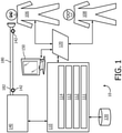
- FIG. 1 schematically illustrates an exemplary embodiment of a system 10 to inexsufflate a subject 106.
- Inexsufflation may loosen and/or expel secretions. Unaided inexsufflation may be difficult and/or impossible for a wide range of patients due to a wide range of different medical reasons.
- the efficacy of an individual inexsufflation (e.g. during an individual respiratory cycle) can be quantified using one or more characteristic parameters, described below.
- System 10 measures, displays, and/or records information pertaining to individual inexsufflations, sets of such inexsufflations, individual treatments including one or more of such inexsufflations, sets of such treatments, days including one or more such treatments, and/or other periods of treatment time including one or more such individual inexsufflations.
- System 10 includes one or more of a pressure generator 140, a user interface 120, a delivery circuit 180, electronic storage 130, one or more sensors 142, one or more processors 110, a control module 111, a parameter determination module 112, an interface module 113, a metric storage module 114, and/or other components.
- System 10 may be dedicated to providing inexsufflations.
- pressure generator 140 of system 10 in FIG. 1 may be integrated, combined, or connected with a ventilator device or system.
- Pressure generator 140 is configured to provide a pressurized flow of breathable gas for fluid communication with the airway of subject 106, e.g. via delivery circuit 180.
- the direction of the fluid communication may be selectively controlled.
- Pressure generator 140 may be configured to adjust one or more of pressure levels, flow, humidity, velocity, acceleration, and/or other parameters of the pressurized flow of breathable gas.
- Delivery circuit 180 is configured to selectively control the direction and/or flow of breathable gas to and/or from the airway of subject 106. Delivery circuit 180 may sometimes be referred to as subject interface 180. Delivery circuit 180 may be configured to operate in one or more of a first mode, a second mode, a third mode, and/or in other modes. One or more modes may correspond to one or more respiratory phases of a breathing cycle. In the first mode, delivery circuit 180 is closed such that substantially no gas is communicated with the airway of subject 106 therethrough. In the second mode delivery circuit 180 is opened to permit gas to be exhausted from the airway of subject 106 through delivery circuit 180, e.g. to ambient atmosphere. In the third mode delivery circuit 180 is opened to permit gas to be delivered to the airway of subject 106 through delivery circuit 180.
- delivery circuit 180 may include one or more of a valve and/or another pressure regulating device.
- delivery circuit 180 may include multiple valves in series and/or in parallel.
- suitable valves and/or other pressure regulating devices include a plug valve, a ball valve, a check valve, a butterfly valve, a solenoid, and/or other pressure regulating devices.
- Pressure regulating devices may be controlled hydraulically, pneumatically, via an electric motor and/or another mode of control configured to open and/or close a valve and/or other pressure control device.
- Delivery circuit 180 may include a conduit 182 and/or a subject interface appliance 184.
- Conduit 182 may include a flexible length of hose, or other conduit, either in single-limb or dual-limb configuration that places subject interface appliance 184 in fluid communication with pressure generator 140.
- Conduit 182 forms a flow path through which the pressurized flow of breathable gas (e.g. air) is communicated between subject interface appliance 184 and pressure generator 140.
- breathable gas e.g. air
- Subject interface appliance 184 of system 10 in FIG. 1 is configured to deliver the pressurized flow of breathable gas to the airway of subject 106.
- subject interface appliance 184 may include any appliance suitable for this function.
- subject interface appliance 184 is configured to engage the airway of subject 106 without an intervening appliance.
- subject interface appliance 184 may include one or more of an endotracheal tube, a nasal cannula, a tracheotomy tube, a nasal mask, a nasal/oral mask, a full-face mask, a total facemask, and/or other interface appliances that communicate a flow of gas with an airway of a subject.
- pressure generator 140 is a dedicated ventilation device and subject interface appliance 184 is configured to be removably coupled with another interface appliance being used to deliver respiratory therapy to subject 106.
- subject interface appliance 184 may be configured to engage with and/or be inserted into an endotracheal tube, a tracheotomy portal, and/or other interface appliances.
- the present disclosure is not limited to these examples, and contemplates delivery of the pressurized flow of breathable gas to subject 106 using any subject interface.
- Electronic storage 130 of system 10 in FIG. 1 comprises electronic storage media that electronically stores information.
- the electronic storage media of electronic storage 130 may include one or both of system storage that is provided integrally (i.e., substantially non-removable) with system 10 and/or removable storage that is removably connectable to system 10 via, for example, a port (e.g., a USB port, a FireWire port, etc.), a slot (e.g., an SD card slot, etc.), or a drive (e.g., a disk drive, etc.).
- a port e.g., a USB port, a FireWire port, etc.
- a slot e.g., an SD card slot, etc.
- a drive e.g., a disk drive, etc.
- Electronic storage 130 may include one or more of optically readable storage media (e.g., optical disks, etc.), magnetically readable storage media (e.g., magnetic tape, magnetic hard drive, floppy drive, etc.), electrical charge-based storage media (e.g., EPROM, EEPROM, RAM, etc.), solid-state storage media (e.g., flash drive, etc.), and/or other electronically readable storage media.
- Electronic storage 130 may store software algorithms, information determined by processor 110, information received via user interface 120, and/or other information that enables system 10 to function properly.
- electronic storage 130 may record or store information pertaining to individual inexsufflations and/or treatments that include one or more inexsufflations (as discussed elsewhere herein), and/or other information.
- Electronic storage 130 may be a separate component within system 10, or electronic storage 130 may be provided integrally with one or more other components of system 10 (e.g., processor 110).
- User interface 120 of system 10 in FIG. 1 is configured to provide an interface between system 10 and a user (e.g., user 108, subject 106, a caregiver, a therapy decision-maker, etc.) through which the user can provide information to and receive information from system 10.
- a user e.g., user 108, subject 106, a caregiver, a therapy decision-maker, etc.
- information data, results, and/or instructions and any other communicable items, collectively referred to as "information,” to be communicated between the user and system 10.
- An example of information that may be conveyed to user 108 is a report detailing quantative information pertaining to individual inexsufflations throughout a period during which the subject is receiving treatment and/or therapy.
- Examples of interface devices suitable for inclusion in user interface 120 include a keypad, buttons, switches, a keyboard, knobs, levers, a display screen, an electronic display 150 configured to display information, a touch screen, speakers, a microphone, an indicator light, an audible alarm, and a printer. Information may be provided to user 108 or subject 106 by user interface 120 in the form of auditory signals, visual signals, tactile signals, and/or other sensory signals.
- electronic display 150 is depicted in FIG. 1 as a separate entity from user interface 120, this is for illustrative purposes only. In some embodiments, electronic display 150 may be integrated, embedded, and/or combined with user interface 120.
- user interface 120 may be integrated with a removable storage interface provided by electronic storage 130.
- information is loaded into system 10 from removable storage (e.g., a smart card, a flash drive, a removable disk, etc.) that enables the user(s) to customize system 10.
- removable storage e.g., a smart card, a flash drive, a removable disk, etc.
- Other exemplary input devices and techniques adapted for use with system 10 as user interface 120 include, but are not limited to, an RS-232 port, RF link, an IR link, modem (telephone, cable, Ethernet, internet or other). In short, any technique for communicating information with system 10 is contemplated as user interface 120.
- One or more sensors 142 of system 10 in FIG. 1 are configured to generate output signals conveying measurements related to parameters of respiratory airflow and/or airway mechanics. These parameters may include one or more of flow, (airway) pressure, humidity, velocity, acceleration, and/or other gas or respiratory parameters. These parameters may pertain to one or more gas levels of the pressurized flow of breathable gas provided through pressure generator 140 and/or a flow of gas at or near the airway of subject 106, for example within subject interface appliance 184. As depicted in FIG. 1 , one or more sensors 142 may be in fluid communication with conduit 182 and/or subject interface appliance 184. In some embodiments, one or more sensors 142 may generate output signals related to physiological parameters pertaining to subject 106.
- sensor 142 includes a plurality of sensors operating as described above by generating output signals conveying information related to parameters associated with the state and/or condition of an airway of subject 106, the breathing of subject 106, the gas breathed by subject 106, the composition of the gas breathed by subject 106, the delivery of the gas to the airway of subject 106, and/or a respiratory effort by the subject.
- a parameter may be related to a mechanical unit of measurement of a component of pressure generator 140 (or of a device that pressure generator 140 is integrated, combined, or coupled with) such as valve drive current, rotor speed, motor speed, blower speed, fan speed, or a related measurement that may serve as a proxy for any of the previously listed parameters through a previously known and/or calibrated mathematical relationship.
- Resulting signals or information from one or more sensors 142 may be transmitted to processor 110, user interface 120, electronic storage 130, and/or other components of system 10. This transmission may be wired and/or wireless.
- Processor 110 of system 10 in FIG. 1 is configured to provide information processing capabilities in system 10.
- processor 110 includes one or more of a digital processor, an analog processor, a digital circuit designed to process information, an analog circuit designed to process information, a state machine, and/or other mechanisms for electronically processing information.
- processor 110 is depicted in FIG. 1 as a single entity, this is for illustrative purposes only. In some embodiments, processor 110 includes a plurality of processing units.
- processor 110 is configured to execute one or more computer program modules.
- the one or more computer program modules include one or more of control module 111, parameter determination module 112, interface module 113, metric storage module 114, and/or other modules.
- Processor 110 may be configured to execute modules 111-114 by software; hardware; firmware; some combination of software, hardware, and/or firmware; and/or other mechanisms for configuring processing capabilities on processor 110.
- modules 111-114 are illustrated in FIG. 1 as being co-located within a single processing unit, in embodiments in which processor 110 includes multiple processing units, one or more of modules 111-114 may be located remotely from the other modules.
- the description of the functionality provided by the different modules 111-114 described herein is for illustrative purposes, and is not intended to be limiting, as any of modules 111-114 may provide more or less functionality than is described.
- one or more of modules 111-114 may be eliminated, and some or all of its functionality may be incorporated, shared, integrated into, and/or otherwise provided by other ones of modules 111-114.
- processor 110 may be configured to execute one or more additional modules that may perform some or all of the functionality attributed below to one of modules 111-114.
- Parameter determination module 112 of system 10 in FIG. 1 is configured to determine one or more gas parameters, respiratory parameters, and/or other parameters from output signals generated by sensor(s) 142.
- the one or more gas parameter may include and/or be related to one or more of (peak) flow, flow rate, (tidal) volume, pressure, temperature, humidity, velocity, acceleration, gas composition (e.g. concentration(s) of one or more constituents such as, e.g., CO 2 ), thermal energy dissipated, (intentional) gas leak, and/or other measurements related to the (pressurized) flow of breathable gas.
- One or more respiratory parameters may be derived from gas parameters and/or other output signals conveying measurements of the pressurized flow of breathable gas.
- the one or more respiratory parameters may include one or more of respiratory rate, breathing period, inhalation time or period, exhalation time or period, respiration flow curve shape, transition time from inhalation to exhalation and/or vice versa, transition time from peak inhalation flow rate to peak exhalation flow rate and/or vice versa, respiration pressure curve shape, maximum proximal pressure drop (per breathing cycle and/or phase), peak cough flow, average (or otherwise aggregated) cough flow, inspiratory tidal volume (for one or more respiratory cycles), expiratory tidal volume (for one or more respiratory cycles), and/or other respiratory parameters.
- Respiratory parameters may be determined on a breath-by-breath basis, on a cough-by-cough basis, and/or at other intervals.
- a peak cough flow parameter may be determined for individual respiratory cycles and/or individual inexsufflations.
- the peak cough flow parameter may be used as a basis for a determination how effectively subject 106 is able to clear secretions, how clear the airway of subject 106 is, and/or any other determination related to inexsufflation, respiratory therapy, and/or the condition of subject 106.
- inspiratory tidal volume may be determined for individual respiratory cycles and/or individual inexsufflations.
- the inspiratory tidal volume may be used as a basis for a determination how effectively subject 106 is able to clear secretions, how clear the airway of subject 106 is, and/or any other determination related to inexsufflation, respiratory therapy, and/or the condition of subject 106. Using other parameters described herein in forming such a determination is contemplated within the scope of this disclosure. It is noted that by virtue of the systems and methods of inexsufflating subjects as described herein, such a determination may be formed by objective standards.
- determination of the peak cough flow parameter (and/or other parameters as described herein) by parameter determination module 112 may account and/or compensate for a length of conduit 182 (and/or volume of breathable gas within one or more components of delivery circuit 180) used between a particular sensor 142 and the airway of subject 106.
- a sensor 142 used to generate output signals conveying information related to the peak cough flow parameter may be disposed at or near pressure generator 140, which may be separated from the airway of subject 106 by, at least, a predetermined length of conduit 182 (and thus a predetermined volume of breathable gas therewithin).
- the length of conduit 182 may be about 3 feet, about 4 feet, about 6 feet, about 9 feet, about 12 feet, and/or other length. Common pertinent lengths of conduit 182 in mechanical ventilation systems may be between about 6 feet and about 9 feet. Parameter determination module 112 may be calibrated accordingly as compensation for the part of delivery circuit 180 disposed between a particular sensor 142 and the airway of subject 106.
- parameter determination module 112 is configured to determine one or more of SpO 2 level, heart rate, respiratory rate, VC, EVC, IVC, FEV0.75, FEV1, FEV3, FEV6, FVC, FEV0.75/VC, FEV0.75/FVC, FEV1/VC, FEV1%, FEV3/VC, FEV0.75/FEV6, FEV1/FEV6, MEF75, MEF50, MEF25, MMEF, MEF50/VC, MEF50/FVC, MVV, FIV1, FIVC, PIF, FIV1%, MIF25, MIF50, MIF75, R50, MET, TV, ERV, IRV, IC, FRC, RV, TLC, FRC/TLC, RV/TLC, and/or other parameters, as well as any combinations/ratios thereof.
- One or more of these parameters may be displayed using user interface 120, electronic display 150, and/or interface module 113, and/or stored using electronic storage 130 and/or metric storage module 114,
- Control module 111 of system 10 in FIG. 1 is configured to control operation of system 10 during inexsufflation of subject 106.
- Control module 111 may be configured to control pressure generator 140 to adjust one or more levels of one or more gas parameters of the pressurized flow of breathable gas in accordance with one or more of a (respiratory) therapy regimen, one or more algorithms that control adjustments and/or changes in the pressurized flow of breathable gas, and/or other factors.
- Control module 111 may be configured to control pressure generator 140 such that one or more gas parameters of the pressurized flow of breathable gas are varied over time in accordance with a respiratory therapy regimen and/or treatment.
- Control module 111 may be configured to control pressure generator 140 to provide the pressurized flow of breathable gas at inhalation pressure levels during inhalation phases, and/or at exhalation pressure levels during exhalation phases.
- pressure of the pressurized flow of breathable gas may be elevated (e.g., about ambient atmosphere) during inhalation to insufflate subject 106.
- control module 111 one or more of a flow rate, an insufflation pressure, and/or an inhaled volume may be controlled by control module 111.
- control module 111 may be configured to cause pressure generator 140 to reduce pressure of the pressurized flow of breathable gas (e.g., to below ambient atmosphere and/or to a negative pressure, or some other pressure lower than the insufflation pressure) to cause the gas in the lungs and/or airway of subject 106 to be expelled and/or drawn out quickly, thereby exsufflating subject 106.
- pressure generator 140 to reduce pressure of the pressurized flow of breathable gas (e.g., to below ambient atmosphere and/or to a negative pressure, or some other pressure lower than the insufflation pressure) to cause the gas in the lungs and/or airway of subject 106 to be expelled and/or drawn out quickly, thereby exsufflating subject 106.
- Parameters determined by parameter determination module 112 and/or received through one or more sensors 142 may be used by control module 111, e.g. in a feedback manner, to adjust therapy modes/settings/operations of system 10.
- signals and/or information received through user interface 120 may be used by control module 111, e.g. in a feedback manner, to adjust one or more therapy modes/settings/operations of system 10.
- user 108 may (e.g. manually) control one or more pressure levels used during operation of system 10 through user interface 120.
- Control module 111 may be configured to time its operations relative to the transitional moments in the breathing cycle of a subject, over multiple breath cycles, and/or in any other relation to any detected events and/or occurrences.
- control module 111 may be governed through programmatic control, e.g. by an algorithm implemented through instructions that are executed by control module 111.
- Such an algorithm may be designed to titrate operating conditions of system 10 such that a target operating condition is reached and/or accomplished over time.
- the algorithm may use a target peak cough flow for individual inexsufflations.
- the algorithm may adjust one or more gas parameters of the pressurized flow of breathable gas, such as for example the inspiratory pressure level, based on the determine peak cough flow parameter of one or more recent inexsufflations.
- the algorithm may be designed to reach a target inspiratory tidal volume for individual inexsufflations.
- Interface module 113 of system 10 in FIG. 1 is configured to control user interface 120 and/or electronic display 150 to display information.
- the displayed information may pertain to (or be based on) one or more of the generated output signals, one or more parameters as determined by parameter determination module 112, including but not limited to the peak cough flow parameter and the inspiratory tidal volume, and/or other information.
- the displayed information may be an aggregation of one or more determined parameters.
- the displayed information may be displayed in real-time, thus providing immediate feedback on the operation of system 10 and/or the efficacy of the treatment while the treatment is being administered to subject 106.
- Metric storage module 114 of system 10 in FIG. 1 is configured to derive, determine, and/or store information on electronic storage 130.
- the derived, determined, and/or stored information may be based on one or more generated output signals from one or more sensors 142, one or more determined parameters from parameter determination module 112, one or more operating conditions of system 10 as controlled through control module 111, and/or other information related to the operation of system 10.
- metric storage module 114 may be configured to derive and/or determine metrics based on individual inexsufflations, sets of such inexsufflations, individual treatments including one or more of such inexsufflations, sets of such treatments, days including one or more such treatments, and/or other periods of treatment time including one or more such individual inexsufflations.
- Metric storage module 114 may be configured to subsequently store such metrics and/or other information as described herein on electronic storage.
- the derived and/or stored metrics include one or more of number of coughs per treatment, number of treatments per day, number of days or treatment, average (or otherwise aggregated) peak cough flow per treatment, average (or otherwise aggregated) peak cough flow per day that includes one or more treatments, average (or otherwise aggregated) inspiratory tidal volume, average (or otherwise aggregated) delivered pressure level for insufflation and/or exsufflation per individual inexsufflation, treatment, and/or day that includes one or more treatments, and/or other information pertaining to the treatment described herein.
- the information stored by metric storage module 114 may be an aggregation of one or more determined parameters.
- the stored information is stored on removable electronic storage such that review and/or analysis may be performed after one or more treatments.
- the stored information may be reviewed at a doctor's office, by virtue of using a software application, and/or remotely through a network-connected computing platform. Such review and/or analysis may reveal trends in one or more parameters over time.
- Such review and/or analysis may be used to adjust a therapy regimen for subject 106.
- Such review and/or analysis may be used to verify and/or quantify a level of compliance with a prescribed therapy regimen.
- system 10 may transfer the stored information, e.g. through removable electronic storage and/or a network connection, to a client computing platform configured to perform the review and/or analysis described herein.
- client computing platform may be further configured to present the stored information, and/or any results from the described review and/or analysis, to a user of the client computing platform, e.g. user 108.
- a client computing platform may include one or more of a desktop computer, a laptop computer, a tablet computing device, a handheld computer, a NetBook, a smartphone, a gaming console, an interactive television, and/or other computing platform or computing device.
- pressure generator 140 by the electronic processor 110 and/or its modules is not intended to be limiting.
- Other controllers for opening pressure generator 140 responsive to pressurization along delivery circuit 180 fall within the scope of this disclosure.
- Other mechanical controllers are also contemplated.
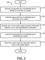
- FIG. 2 illustrates a method 200 of inexsufflating a subject.
- the operations of method 200 presented below are intended to be illustrative. In some embodiments, method 200 may be accomplished with one or more additional operations not described, and/or without one or more of the operations discussed. Additionally, the order in which the operations of method 200 are illustrated in FIG. 2 and described below is not intended to be limiting.
- method 200 may be implemented in one or more processing devices (e.g., a digital processor, an analog processor, a digital circuit designed to process information, an analog circuit designed to process information, a state machine, and/or other mechanisms for electronically processing information).
- the one or more processing devices may include one or more devices executing some or all of the operations of method 200 in response to instructions stored electronically on an electronic storage medium.
- the one or more processing devices may include one or more devices configured through hardware, firmware, and/or software to be specifically designed for execution of one or more of the operations of method 200.
- a pressurized flow of breathable gas is generated for delivery to the airway of a subject.
- operation 202 is performed by a pressure generator the same as or similar to pressure generator 140 (shown in FIG. 1 and described herein).
- operation 204 the pressurized flow of breathable gas is guided to the airway of the subject.
- operation 204 is performed by a delivery circuit the same as or similar to delivery circuit 180 (shown in FIG. 1 and described herein).
- one or more output signals are generated that convey information related to one or more parameters, wherein the one or more parameters include one or both of a gas parameter and/or a respiratory parameter.
- operation 206 is performed by a sensor the same as or similar to sensor 142 (shown in FIG. 1 and described herein).
- operation 208 the pressurized flow of breathable gas is controlled to inexsufflate the subject.
- operation 208 is performed by a control module the same as or similar to control module 111 (shown in FIG. 1 and described herein).
- a peak cough flow parameter is determined based on the one or more generated output signals.
- operation 210 is performed by a parameter determination module the same as or similar to parameter determination module 112 (shown in FIG. 1 and described herein).
- any reference signs placed between parentheses shall not be construed as limiting the claim.
- the word “comprising” or “including” does not exclude the presence of elements or steps other than those listed in a claim.
- several of these means may be embodied by one and the same item of hardware.
- the word “a” or “an” preceding an element does not exclude the presence of a plurality of such elements.
- any device claim enumerating several means several of these means may be embodied by one and the same item of hardware.
- the mere fact that certain elements are recited in mutually different dependent claims does not indicate that these elements cannot be used in combination.
Claims (4)
- Système (10) configuré pour insuffler/exsuffler un sujet, le système comprenant ;un générateur de pression (140) configuré pour générer un flux de gaz respiratoire pour l'acheminement vers les voies respiratoires du sujet ;un circuit d'alimentation (180) comprenant un conduit (182) et étant configuré pour guider le flux pressurisé de gaz respiratoire vers les voies respiratoires du sujet ;un ou plusieurs capteurs (142) configurés pour générer un ou plusieurs signaux de sortie transmettant les informations associées à un ou plusieurs paramètres, dans lequel un ou plusieurs paramètres comprennent un paramètre respiratoire ; etun ou plusieurs processeurs (110) configurés pour exécuter les modules de programme informatique, les modules de programme informatique comprenant :un module de commande (111) configuré pour commander le générateur de pression pour insuffler/exsuffler le sujet ; etun module de détermination de paramètre (112) configuré pour déterminer un paramètre de débit de pointe à la toux et un volume respiratoire inspiratoire basé sur un ou plusieurs signaux de sortie, dans lequel la détermination du paramètre de débit de la pointe à la toux comprend la compensation (i) pour une longueur du conduit (182) entre un capteur particulier parmi un ou plusieurs capteurs (142) et les voies aériennes du sujet et/ou (ii) pour un volume de gaz respiratoire à l'intérieur d'un ou de plusieurs composants du circuit d'alimentation (180) placé entre un capteur particulier parmi un ou plusieurs capteurs (142) et les voies aériennes du sujet,dans lequel le module de commande (111) est configuré pour utiliser, en retour, le paramètre de débit de pointe à la toux d'une ou de plusieurs insufflations/exsufflations récentes déterminées par le module de détermination de paramètre (112) et le volume respiratoire inspiratoire déterminé par le module de détermination de paramètre (112) pour ajuster un ouplusieurs paramètres de gaz du flux pressurisé de gaz respiratoire de façon à obtenir un débit de pointe à la toux cible pour des insufflations/exsufflations individuelles et un volume respiratoire inspiratoire cible pour les insufflations/exsufflations individuelles.
- Système selon la revendication 1, comprenant en outre :un écran électronique (150) configuré pour afficher les informations ; etun module d'interface (113) configuré pour commander l'écran électronique de sorte que les informations affichées sont basées sur le paramètre de débit de pointe à la toux.
- Système selon la revendication 2, dans lequel les informations affichées sont en outre basées sur le volume respiratoire inspiratoire.
- Système selon la revendication 1, comprenant en outre :un stockage électronique (130) comprenant un support de stockage électronique configuré pour stocker élec-troniquement les informations ; etun module de stockage métrique (114) configuré pour stocker les informations sur la base d'un ou de plusieurs signaux de sortie générés, dans lequel les informations sont stockées sur le stockage électronique.
Applications Claiming Priority (2)
| Application Number | Priority Date | Filing Date | Title |
|---|---|---|---|
| US201261650079P | 2012-05-22 | 2012-05-22 | |
| PCT/IB2013/053919 WO2013175345A1 (fr) | 2012-05-22 | 2013-05-14 | Assistance à la toux et système et procédé de mesure, ainsi qu'applications associées |
Publications (2)
| Publication Number | Publication Date |
|---|---|
| EP2852321A1 EP2852321A1 (fr) | 2015-04-01 |
| EP2852321B1 true EP2852321B1 (fr) | 2022-03-09 |
Family
ID=48700655
Family Applications (1)
| Application Number | Title | Priority Date | Filing Date |
|---|---|---|---|
| EP13732250.9A Active EP2852321B1 (fr) | 2012-05-22 | 2013-05-14 | Assistance à la toux et système de mesure |
Country Status (5)
| Country | Link |
|---|---|
| US (1) | US11202875B2 (fr) |
| EP (1) | EP2852321B1 (fr) |
| JP (1) | JP6820656B2 (fr) |
| CN (1) | CN104334080B (fr) |
| WO (1) | WO2013175345A1 (fr) |
Families Citing this family (7)
| Publication number | Priority date | Publication date | Assignee | Title |
|---|---|---|---|---|
| JP6480598B2 (ja) | 2015-04-02 | 2019-03-13 | ヒル−ロム サービシーズ プライヴェート リミテッド | 呼吸装置用マニホールド |
| US10946150B2 (en) * | 2015-05-05 | 2021-03-16 | Koninklijke Philips N.V. | System and methods for improved cough segmentation |
| WO2017032882A1 (fr) * | 2015-08-26 | 2017-03-02 | Koninklijke Philips N.V. | Insufflation-exsufflation mécanique |
| WO2018026549A1 (fr) * | 2016-08-02 | 2018-02-08 | Bougatef Adel | Appareil pour fournir une thérapie de ventilation percussive à une voie respiratoire d'un patient |
| DE102016013740A1 (de) * | 2016-11-17 | 2018-05-17 | Drägerwerk AG & Co. KGaA | System zum Beatmen von Patienten |
| KR102519584B1 (ko) | 2017-12-29 | 2023-04-10 | 삼성전자주식회사 | 사용자 호흡에 대한 운동 상태 정보를 획득하기 위한 전자 장치 및 이의 제어 방법 |
| CN108543182B (zh) * | 2018-05-02 | 2020-08-21 | 北京雅果科技有限公司 | 无创呼吸机用辅助排痰方法及无创呼吸机 |
Family Cites Families (15)
| Publication number | Priority date | Publication date | Assignee | Title |
|---|---|---|---|---|
| US5884622A (en) * | 1996-12-20 | 1999-03-23 | University Of Manitoba | Automatic determination of passive elastic and resistive properties of the respiratory system during assisted mechanical ventilation |
| US6920875B1 (en) * | 1999-06-15 | 2005-07-26 | Respironics, Inc. | Average volume ventilation |
| IL145461A (en) | 2001-09-16 | 2006-09-05 | Alyn Woldenberg Family Hospita | Breathing and coughing device |
| WO2007008825A2 (fr) * | 2005-07-11 | 2007-01-18 | Emory University | Systeme et procede de liberation optimisee d'un aerosol dans les voies respiratoires |
| WO2007144767A2 (fr) * | 2006-02-02 | 2007-12-21 | Be Eri Eliezer | Appareil respiratoire |
| US20100050085A1 (en) * | 2006-09-29 | 2010-02-25 | Draeger Medical Systems, Inc. | System for processing, deriving and displaying relationships among patient medical parameters |
| EP2167178A1 (fr) | 2007-06-01 | 2010-03-31 | Intensive Care On-line Network, INC. | Ventilateur et système de ventilation |
| CN102215891B (zh) * | 2008-11-19 | 2015-06-17 | 皇家飞利浦电子股份有限公司 | 吹气-呼气系统 |
| BR112012001413B1 (pt) * | 2009-07-24 | 2021-05-18 | Koninklijke Philips N.V. | dispositivo para ajudar a tossir |
| BR112012008496A2 (pt) * | 2009-10-16 | 2019-09-24 | Koninl Philips Electronics Nv | sistema de ventilação configurado para gerar um fluxo pressurizado de gás respiravel que é liberado ás vias aéreas de um individuo para ventilar mecanicamente o individuo |
| US20110138311A1 (en) * | 2009-12-04 | 2011-06-09 | Nellcor Puritan Bennett Llc | Display Of Respiratory Data On A Ventilator Graphical User Interface |
| CN103052420B (zh) * | 2010-05-22 | 2015-07-15 | 马奎特紧急护理公司 | 具有流量估算的呼吸系统 |
| IN2013CN01313A (fr) * | 2010-08-13 | 2015-08-07 | Koninkl Philips Electronics Nv | |
| US9855395B2 (en) * | 2011-09-13 | 2018-01-02 | Koninklijke Philips N.V. | Pressure based gas leak testing |
| CN104203320B (zh) * | 2012-03-21 | 2017-05-03 | 皇家飞利浦有限公司 | 用于在吹排气期间控制吹气压力的系统与方法 |
-
2013
- 2013-05-14 CN CN201380026630.XA patent/CN104334080B/zh active Active
- 2013-05-14 WO PCT/IB2013/053919 patent/WO2013175345A1/fr active Application Filing
- 2013-05-14 US US14/402,201 patent/US11202875B2/en active Active
- 2013-05-14 JP JP2015513311A patent/JP6820656B2/ja active Active
- 2013-05-14 EP EP13732250.9A patent/EP2852321B1/fr active Active
Also Published As
| Publication number | Publication date |
|---|---|
| WO2013175345A1 (fr) | 2013-11-28 |
| CN104334080A (zh) | 2015-02-04 |
| EP2852321A1 (fr) | 2015-04-01 |
| JP2015520648A (ja) | 2015-07-23 |
| US20150136134A1 (en) | 2015-05-21 |
| WO2013175345A8 (fr) | 2014-12-31 |
| CN104334080B (zh) | 2017-05-31 |
| JP6820656B2 (ja) | 2021-01-27 |
| US11202875B2 (en) | 2021-12-21 |
Similar Documents
| Publication | Publication Date | Title |
|---|---|---|
| EP2852321B1 (fr) | Assistance à la toux et système de mesure | |
| US10137262B2 (en) | Synchronizing mechanical in-exsufflation and diaphragmatic pacing | |
| CN107106801B (zh) | 使用呼吸的吸入和呼出阶段两者上估计的患者肺顺应性检测通气机与患者断开的系统和方法 | |
| AU2011346629B2 (en) | System and method for inexsufflating a subject | |
| EP2747817B1 (fr) | Appareil de gestion d'un dispositif thérapeutique de ventilation | |
| US9895083B2 (en) | Non-invasive ventilation measurement | |
| AU2011346629A1 (en) | System and method for inexsufflating a subject | |
| EP2994182B1 (fr) | Système de soutien sous pression pour thérapie par breath stacking | |
| US20130284174A1 (en) | Respiration-rate dependent respiratory assistance | |
| JP2015520648A5 (fr) | ||
| US20140326242A1 (en) | Sysems and methods for using partial co2 rebreathing integrated in a ventilator and measurements thereof to determine noninvasive cardiac output | |
| EP2846861B1 (fr) | Systèmes de détermination de la fraction d'oxygène inspiré pendant la ventilation | |
| US11291786B2 (en) | Reducing hypercapnic respiratory failure during mechanical ventilation | |
| JP2015519119A5 (fr) | ||
| WO2021110710A1 (fr) | Systèmes et procédés de surveillance métabolique | |
| EP2688620B1 (fr) | SYSTÈMES POUR GÉRER l' APNÉE DU SOMMEIL CENTRALE EN CONTRÔLANT LE VOLUME RÉTROGRADE CUMULÉ | |
| WO2016103145A1 (fr) | Systèmes et procédés pour commande de ventilateur comprenant la détermination de la fatigue d'un patient et du niveau de ventilation à aide inspiratoire (vai) |
Legal Events
| Date | Code | Title | Description |
|---|---|---|---|
| PUAI | Public reference made under article 153(3) epc to a published international application that has entered the european phase |
Free format text: ORIGINAL CODE: 0009012 |
|
| 17P | Request for examination filed |
Effective date: 20141222 |
|
| AK | Designated contracting states |
Kind code of ref document: A1 Designated state(s): AL AT BE BG CH CY CZ DE DK EE ES FI FR GB GR HR HU IE IS IT LI LT LU LV MC MK MT NL NO PL PT RO RS SE SI SK SM TR |
|
| AX | Request for extension of the european patent |
Extension state: BA ME |
|
| DAX | Request for extension of the european patent (deleted) | ||
| STAA | Information on the status of an ep patent application or granted ep patent |
Free format text: STATUS: EXAMINATION IS IN PROGRESS |
|
| 17Q | First examination report despatched |
Effective date: 20191218 |
|
| RAP1 | Party data changed (applicant data changed or rights of an application transferred) |
Owner name: KONINKLIJKE PHILIPS N.V. |
|
| STAA | Information on the status of an ep patent application or granted ep patent |
Free format text: STATUS: EXAMINATION IS IN PROGRESS |
|
| GRAP | Despatch of communication of intention to grant a patent |
Free format text: ORIGINAL CODE: EPIDOSNIGR1 |
|
| STAA | Information on the status of an ep patent application or granted ep patent |
Free format text: STATUS: GRANT OF PATENT IS INTENDED |
|
| INTG | Intention to grant announced |
Effective date: 20211104 |
|
| GRAS | Grant fee paid |
Free format text: ORIGINAL CODE: EPIDOSNIGR3 |
|
| GRAA | (expected) grant |
Free format text: ORIGINAL CODE: 0009210 |
|
| STAA | Information on the status of an ep patent application or granted ep patent |
Free format text: STATUS: THE PATENT HAS BEEN GRANTED |
|
| AK | Designated contracting states |
Kind code of ref document: B1 Designated state(s): AL AT BE BG CH CY CZ DE DK EE ES FI FR GB GR HR HU IE IS IT LI LT LU LV MC MK MT NL NO PL PT RO RS SE SI SK SM TR |
|
| REG | Reference to a national code |
Ref country code: GB Ref legal event code: FG4D |
|
| REG | Reference to a national code |
Ref country code: CH Ref legal event code: EP Ref country code: AT Ref legal event code: REF Ref document number: 1473477 Country of ref document: AT Kind code of ref document: T Effective date: 20220315 |
|
| REG | Reference to a national code |
Ref country code: DE Ref legal event code: R096 Ref document number: 602013081072 Country of ref document: DE |
|
| REG | Reference to a national code |
Ref country code: IE Ref legal event code: FG4D |
|
| REG | Reference to a national code |
Ref country code: LT Ref legal event code: MG9D |
|
| REG | Reference to a national code |
Ref country code: NL Ref legal event code: MP Effective date: 20220309 |
|
| PG25 | Lapsed in a contracting state [announced via postgrant information from national office to epo] |
Ref country code: SE Free format text: LAPSE BECAUSE OF FAILURE TO SUBMIT A TRANSLATION OF THE DESCRIPTION OR TO PAY THE FEE WITHIN THE PRESCRIBED TIME-LIMIT Effective date: 20220309 Ref country code: RS Free format text: LAPSE BECAUSE OF FAILURE TO SUBMIT A TRANSLATION OF THE DESCRIPTION OR TO PAY THE FEE WITHIN THE PRESCRIBED TIME-LIMIT Effective date: 20220309 Ref country code: NO Free format text: LAPSE BECAUSE OF FAILURE TO SUBMIT A TRANSLATION OF THE DESCRIPTION OR TO PAY THE FEE WITHIN THE PRESCRIBED TIME-LIMIT Effective date: 20220609 Ref country code: LT Free format text: LAPSE BECAUSE OF FAILURE TO SUBMIT A TRANSLATION OF THE DESCRIPTION OR TO PAY THE FEE WITHIN THE PRESCRIBED TIME-LIMIT Effective date: 20220309 Ref country code: HR Free format text: LAPSE BECAUSE OF FAILURE TO SUBMIT A TRANSLATION OF THE DESCRIPTION OR TO PAY THE FEE WITHIN THE PRESCRIBED TIME-LIMIT Effective date: 20220309 Ref country code: BG Free format text: LAPSE BECAUSE OF FAILURE TO SUBMIT A TRANSLATION OF THE DESCRIPTION OR TO PAY THE FEE WITHIN THE PRESCRIBED TIME-LIMIT Effective date: 20220609 |
|
| REG | Reference to a national code |
Ref country code: AT Ref legal event code: MK05 Ref document number: 1473477 Country of ref document: AT Kind code of ref document: T Effective date: 20220309 |
|
| PG25 | Lapsed in a contracting state [announced via postgrant information from national office to epo] |
Ref country code: LV Free format text: LAPSE BECAUSE OF FAILURE TO SUBMIT A TRANSLATION OF THE DESCRIPTION OR TO PAY THE FEE WITHIN THE PRESCRIBED TIME-LIMIT Effective date: 20220309 Ref country code: GR Free format text: LAPSE BECAUSE OF FAILURE TO SUBMIT A TRANSLATION OF THE DESCRIPTION OR TO PAY THE FEE WITHIN THE PRESCRIBED TIME-LIMIT Effective date: 20220610 Ref country code: FI Free format text: LAPSE BECAUSE OF FAILURE TO SUBMIT A TRANSLATION OF THE DESCRIPTION OR TO PAY THE FEE WITHIN THE PRESCRIBED TIME-LIMIT Effective date: 20220309 |
|
| PG25 | Lapsed in a contracting state [announced via postgrant information from national office to epo] |
Ref country code: NL Free format text: LAPSE BECAUSE OF FAILURE TO SUBMIT A TRANSLATION OF THE DESCRIPTION OR TO PAY THE FEE WITHIN THE PRESCRIBED TIME-LIMIT Effective date: 20220309 |
|
| PG25 | Lapsed in a contracting state [announced via postgrant information from national office to epo] |
Ref country code: SM Free format text: LAPSE BECAUSE OF FAILURE TO SUBMIT A TRANSLATION OF THE DESCRIPTION OR TO PAY THE FEE WITHIN THE PRESCRIBED TIME-LIMIT Effective date: 20220309 Ref country code: SK Free format text: LAPSE BECAUSE OF FAILURE TO SUBMIT A TRANSLATION OF THE DESCRIPTION OR TO PAY THE FEE WITHIN THE PRESCRIBED TIME-LIMIT Effective date: 20220309 Ref country code: RO Free format text: LAPSE BECAUSE OF FAILURE TO SUBMIT A TRANSLATION OF THE DESCRIPTION OR TO PAY THE FEE WITHIN THE PRESCRIBED TIME-LIMIT Effective date: 20220309 Ref country code: PT Free format text: LAPSE BECAUSE OF FAILURE TO SUBMIT A TRANSLATION OF THE DESCRIPTION OR TO PAY THE FEE WITHIN THE PRESCRIBED TIME-LIMIT Effective date: 20220711 Ref country code: ES Free format text: LAPSE BECAUSE OF FAILURE TO SUBMIT A TRANSLATION OF THE DESCRIPTION OR TO PAY THE FEE WITHIN THE PRESCRIBED TIME-LIMIT Effective date: 20220309 Ref country code: EE Free format text: LAPSE BECAUSE OF FAILURE TO SUBMIT A TRANSLATION OF THE DESCRIPTION OR TO PAY THE FEE WITHIN THE PRESCRIBED TIME-LIMIT Effective date: 20220309 Ref country code: CZ Free format text: LAPSE BECAUSE OF FAILURE TO SUBMIT A TRANSLATION OF THE DESCRIPTION OR TO PAY THE FEE WITHIN THE PRESCRIBED TIME-LIMIT Effective date: 20220309 Ref country code: AT Free format text: LAPSE BECAUSE OF FAILURE TO SUBMIT A TRANSLATION OF THE DESCRIPTION OR TO PAY THE FEE WITHIN THE PRESCRIBED TIME-LIMIT Effective date: 20220309 |
|
| PG25 | Lapsed in a contracting state [announced via postgrant information from national office to epo] |
Ref country code: PL Free format text: LAPSE BECAUSE OF FAILURE TO SUBMIT A TRANSLATION OF THE DESCRIPTION OR TO PAY THE FEE WITHIN THE PRESCRIBED TIME-LIMIT Effective date: 20220309 Ref country code: IS Free format text: LAPSE BECAUSE OF FAILURE TO SUBMIT A TRANSLATION OF THE DESCRIPTION OR TO PAY THE FEE WITHIN THE PRESCRIBED TIME-LIMIT Effective date: 20220709 Ref country code: AL Free format text: LAPSE BECAUSE OF FAILURE TO SUBMIT A TRANSLATION OF THE DESCRIPTION OR TO PAY THE FEE WITHIN THE PRESCRIBED TIME-LIMIT Effective date: 20220309 |
|
| REG | Reference to a national code |
Ref country code: DE Ref legal event code: R097 Ref document number: 602013081072 Country of ref document: DE |
|
| REG | Reference to a national code |
Ref country code: CH Ref legal event code: PL |
|
| PLBE | No opposition filed within time limit |
Free format text: ORIGINAL CODE: 0009261 |
|
| STAA | Information on the status of an ep patent application or granted ep patent |
Free format text: STATUS: NO OPPOSITION FILED WITHIN TIME LIMIT |
|
| REG | Reference to a national code |
Ref country code: BE Ref legal event code: MM Effective date: 20220531 |
|
| PG25 | Lapsed in a contracting state [announced via postgrant information from national office to epo] |
Ref country code: MC Free format text: LAPSE BECAUSE OF FAILURE TO SUBMIT A TRANSLATION OF THE DESCRIPTION OR TO PAY THE FEE WITHIN THE PRESCRIBED TIME-LIMIT Effective date: 20220309 Ref country code: LU Free format text: LAPSE BECAUSE OF NON-PAYMENT OF DUE FEES Effective date: 20220514 Ref country code: LI Free format text: LAPSE BECAUSE OF NON-PAYMENT OF DUE FEES Effective date: 20220531 Ref country code: DK Free format text: LAPSE BECAUSE OF FAILURE TO SUBMIT A TRANSLATION OF THE DESCRIPTION OR TO PAY THE FEE WITHIN THE PRESCRIBED TIME-LIMIT Effective date: 20220309 Ref country code: CH Free format text: LAPSE BECAUSE OF NON-PAYMENT OF DUE FEES Effective date: 20220531 |
|
| 26N | No opposition filed |
Effective date: 20221212 |
|
| PG25 | Lapsed in a contracting state [announced via postgrant information from national office to epo] |
Ref country code: SI Free format text: LAPSE BECAUSE OF FAILURE TO SUBMIT A TRANSLATION OF THE DESCRIPTION OR TO PAY THE FEE WITHIN THE PRESCRIBED TIME-LIMIT Effective date: 20220309 |
|
| GBPC | Gb: european patent ceased through non-payment of renewal fee |
Effective date: 20220609 |
|
| PG25 | Lapsed in a contracting state [announced via postgrant information from national office to epo] |
Ref country code: IE Free format text: LAPSE BECAUSE OF NON-PAYMENT OF DUE FEES Effective date: 20220514 Ref country code: FR Free format text: LAPSE BECAUSE OF NON-PAYMENT OF DUE FEES Effective date: 20220531 |
|
| PG25 | Lapsed in a contracting state [announced via postgrant information from national office to epo] |
Ref country code: GB Free format text: LAPSE BECAUSE OF NON-PAYMENT OF DUE FEES Effective date: 20220609 Ref country code: BE Free format text: LAPSE BECAUSE OF NON-PAYMENT OF DUE FEES Effective date: 20220531 |
|
| PG25 | Lapsed in a contracting state [announced via postgrant information from national office to epo] |
Ref country code: IT Free format text: LAPSE BECAUSE OF FAILURE TO SUBMIT A TRANSLATION OF THE DESCRIPTION OR TO PAY THE FEE WITHIN THE PRESCRIBED TIME-LIMIT Effective date: 20220309 |
|
| PGFP | Annual fee paid to national office [announced via postgrant information from national office to epo] |
Ref country code: DE Payment date: 20220628 Year of fee payment: 11 |
|
| PG25 | Lapsed in a contracting state [announced via postgrant information from national office to epo] |
Ref country code: HU Free format text: LAPSE BECAUSE OF FAILURE TO SUBMIT A TRANSLATION OF THE DESCRIPTION OR TO PAY THE FEE WITHIN THE PRESCRIBED TIME-LIMIT; INVALID AB INITIO Effective date: 20130514 |