EP2852269A2 - Electronic assembly casing and electronic assembly - Google Patents
Electronic assembly casing and electronic assembly Download PDFInfo
- Publication number
- EP2852269A2 EP2852269A2 EP14275195.7A EP14275195A EP2852269A2 EP 2852269 A2 EP2852269 A2 EP 2852269A2 EP 14275195 A EP14275195 A EP 14275195A EP 2852269 A2 EP2852269 A2 EP 2852269A2
- Authority
- EP
- European Patent Office
- Prior art keywords
- circuit board
- heat sink
- casing
- electronic assembly
- cage
- Prior art date
- Legal status (The legal status is an assumption and is not a legal conclusion. Google has not performed a legal analysis and makes no representation as to the accuracy of the status listed.)
- Granted
Links
- 230000008878 coupling Effects 0.000 claims description 10
- 238000010168 coupling process Methods 0.000 claims description 10
- 238000005859 coupling reaction Methods 0.000 claims description 10
- 229920003023 plastic Polymers 0.000 claims description 10
- 239000006260 foam Substances 0.000 claims description 8
- 239000004033 plastic Substances 0.000 claims description 8
- 239000000853 adhesive Substances 0.000 claims description 7
- 230000001070 adhesive effect Effects 0.000 claims description 7
- 239000000463 material Substances 0.000 description 4
- 208000001613 Gambling Diseases 0.000 description 2
- 230000004888 barrier function Effects 0.000 description 2
- 230000006835 compression Effects 0.000 description 1
- 238000007906 compression Methods 0.000 description 1
- 239000004020 conductor Substances 0.000 description 1
- 230000001419 dependent effect Effects 0.000 description 1
- 238000005516 engineering process Methods 0.000 description 1
- 230000001788 irregular Effects 0.000 description 1
- 230000001105 regulatory effect Effects 0.000 description 1
- 230000000630 rising effect Effects 0.000 description 1
- 230000029305 taxis Effects 0.000 description 1
- 238000013022 venting Methods 0.000 description 1
Images


Classifications
-
- H—ELECTRICITY
- H05—ELECTRIC TECHNIQUES NOT OTHERWISE PROVIDED FOR
- H05K—PRINTED CIRCUITS; CASINGS OR CONSTRUCTIONAL DETAILS OF ELECTRIC APPARATUS; MANUFACTURE OF ASSEMBLAGES OF ELECTRICAL COMPONENTS
- H05K7/00—Constructional details common to different types of electric apparatus
- H05K7/20—Modifications to facilitate cooling, ventilating, or heating
- H05K7/2039—Modifications to facilitate cooling, ventilating, or heating characterised by the heat transfer by conduction from the heat generating element to a dissipating body
- H05K7/20409—Outer radiating structures on heat dissipating housings, e.g. fins integrated with the housing
-
- H—ELECTRICITY
- H05—ELECTRIC TECHNIQUES NOT OTHERWISE PROVIDED FOR
- H05K—PRINTED CIRCUITS; CASINGS OR CONSTRUCTIONAL DETAILS OF ELECTRIC APPARATUS; MANUFACTURE OF ASSEMBLAGES OF ELECTRICAL COMPONENTS
- H05K7/00—Constructional details common to different types of electric apparatus
- H05K7/20—Modifications to facilitate cooling, ventilating, or heating
- H05K7/2039—Modifications to facilitate cooling, ventilating, or heating characterised by the heat transfer by conduction from the heat generating element to a dissipating body
-
- H—ELECTRICITY
- H05—ELECTRIC TECHNIQUES NOT OTHERWISE PROVIDED FOR
- H05K—PRINTED CIRCUITS; CASINGS OR CONSTRUCTIONAL DETAILS OF ELECTRIC APPARATUS; MANUFACTURE OF ASSEMBLAGES OF ELECTRICAL COMPONENTS
- H05K5/00—Casings, cabinets or drawers for electric apparatus
- H05K5/02—Details
- H05K5/0213—Venting apertures; Constructional details thereof
Definitions
- the present invention relates to an electronic assembly casing and electronic assembly that are particularly suited to for use in gaming and gambling machines - often referred to as "slot machines".
- gaming and gambling machines such as slot machines
- gaming and gambling machines it is also usually necessary for gaming and gambling machines such as slot machines to comply with certain standards set by government, state or other regulatory bodies relating to the security of the slot machines, as they handle significant revenue streams.
- security requirements to ensure that the machines are not tampered with, either to manipulate payouts to users or the recording of transactions for the purpose of collecting government gaming taxes from machine operators.
- This is in addition to protection from physical attacks aimed at stealing money contained within the machines.
- this protection includes physical security to prevent unauthorised access to the interior of the slot machine and especially the "logic box" that houses the computer system and the operating programs.
- an electronic assembly casing having walls providing an internal chamber and a circuit board mount to mount a circuit board in the internal chamber, the casing further comprising a heat sink cage in one of said walls to accommodate a heat sink of the circuit board when mounted on the circuit board mount.
- the heat sink cage is part of one of the walls.
- the heat sink cage is arranged to extend from the circuit board, when mounted, about a perimeter of the heat sink.
- the casing further comprises a coupling member to couple the heat sink cage to the circuit board and/or heat sink about said perimeter.
- the coupling member may include an adhesive to adhere the heat sink cage to the circuit board about said perimeter.
- the coupling member may comprise a foam body having said adhesive on a portion of the body that faces and adheres to said perimeter of the circuit board when the circuit board is mounted.
- the heat sink cage is in a first wall of the casing that extends, when the circuit board is mounted, in a first plane substantially parallel to a surface of the circuit board mounting the heat sink, the first wall further defining a trench about said cage, the trench extending from said first plane toward said surface of said circuit board.
- At least one of the walls of the trench may be non-perpendicular to said first plane.
- One of the walls of the trench may be a wall of said heat sink cage.
- the trench preferably includes a first trench wall extending from said first plane toward said surface of said circuit board, a second trench wall that is substantially co-planar to said surface of said circuit board and a third trench wall, the third trench wall comprising the wall of the heat sink cage.
- the first and third trench walls may be at substantially mirror opposite angles with respect to the second trench wall.
- the heat sink cage may include a plurality of heat vents.
- the casing comprises a plastics body.
- the plastics body may be substantially transparent.
- the heat sink cage may be formed by at least a part of one of the walls of the casing.
- an electronic assembly comprising an electronic assembly casing as described above and a circuit board mounted to the circuit board mount, the circuit board including a heat sink that extends from the circuit board into the heat sink cage of the casing.
- the present invention seeks to provide an improved electronic assembly casing for a printed circuit board such as a computer, logic box or other electronic assembly for use, for example, in a gaming device.
- the present invention also seeks to provide an improved electronic assembly including such a case.
- an electronic assembly casing can be formed from substantially non-heat-conducting materials such as plastics.
- casing materials in embodiments of the present invention can be selected for properties such as weight and ability to be attractively coloured or patterned and/or moulded in non-box-like shapes.
- the casing can be formed substantially entirely from transparent plastics to enable a user, owner or regulator to visually reassure themselves, while the electronic assembly is installed and in potentially is use, that the electronics assembly (such as a circuit board) contained in the casing is standard and has not been tampered with or includes unexpected components or connections.
- the heat sink cage is substantially sealed to the circuit board about a perimeter of the heat sink. While the heat sink is exposed to the outside world and could theoretically be physically accessed via the vents such as slots, mesh or apertures in the case, the actual electronic components are protected by the heat sink and/or the seal and cannot themselves be accessed.
- a heat generating electronic assembly can be accommodated in a casing that substantially prevents physical access to electronic components of the assembly from the outside world whilst enabling heat to be dissipated via the heat sink.
- a trench is formed around the heat sink cage to allow air to flow over substantially the entirety of a surface of a heat sink accommodated by the cage.
- top bottom
- base front
- rear rear
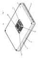
- Figure 1 shows a perspective view of an electronic assembly casing according to one embodiment.
- Figures 2 and 3 are, respectively, top and side views of the casing of Figure 1 .
- the electronic assembly casing 10 has walls 11, 12, 13 (rear and base walls not shown) which define an internal chamber.
- the size and shape of the casing is shown purely for exemplary purposes and could be varied depending on the intended application and end use. Although a box-shaped casing is shown, the casing could be of any size, shape, design or proportion.
- a heat sink cage 20 is formed as part of the top wall 11.
- the heat sink cage 20 includes a plurality of heat vents 21, 22 in the form of slots 21 and circular holes 22.
- the heat sink cage 20 projects above the top wall 11.
- the top wall 11 slopes (11 a) down into the casing towards the base wall (not shown) before flattening out (11 b) and then rising back out (11 c) to form the cage 20.
- the heat sink cage is preferably formed as part of one of the walls (as opposed to being a separate component and joined or otherwise connected to the casing).
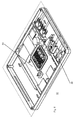
- Figure 4 is a cross-sectional view of the casing 10 of Figure 1 showing aspects of a mounted electronic circuit board 50.
- the casing 10 includes a circuit board mount 15 to mount the circuit board 50 in the internal chamber.
- the circuit board 50 includes a heat sink 60 which is positioned in the heat sink cage 20 when the circuit board is mounted on the circuit board mount 15.
- the heat sink cage 20 is arranged to extend from the circuit board 50, when mounted, about a perimeter of the heat sink. Most preferably, the heat sink cage 20 sits on or couples to the circuit board 50 about said perimeter such that all that is within the caged area is the heat sink, as can be seen in Figure 4 . As the heat sink sits on top of heat producing elements such as processors, it acts as physical block/protection to those elements. The heat sink cage 20 being connected to the circuit board around the trench area prevents someone trying to physically access other elements of the circuit board 50 via the heat vents 21, 22. The trench 11a-11c therefore provides a thermal and mechanical (security) barrier between the area in and around the heat sink and the remainder of the chamber inside the casing.
- the heat sink cage is coupled to the circuit board by a coupling member.
- the coupling member includes an adhesive 16 to adhere the heat sink cage to the circuit board about said perimeter.
- the coupling member includes a foam body such as a foam gasket, strip or pad, optionally having adhesive on a portion of the body that faces and adheres to said perimeter of the circuit board when the circuit board is mounted.
- the foam gasket sits beneath the base of the trench (11 b) and fills any gap between the bottom of the trench in the case and the surface of the circuit board and/or the base of the heat sink (depending on whether the foam gasket couples to the circuit board or to a portion of the heat sink).
- This arrangement allows any irregular gaps that may be present in that area to be filled and serves as a barrier to air heated by the heat sink from entering the main chamber inside of the casing.
- the gasket is optional if the gap is minimal between the bottom of the trench in the case and the base of the heat sink or surface of the circuit board.
- the casing has a plastics body.
- the plastics body is substantially transparent.
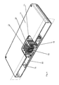
- Figure 5 is a perspective view of the interior of the casing of Figure 1 showing an example circuit board mounted in place.
- the casing 10 preferably also includes a number of input/output connector access ports 30 which match to input/output connectors of the circuit board when mounted (again, in preferred embodiments the casing and connectors between them block physical access into the internal chamber of the casing in which the electronics of the circuit board is housed.
- circuit board and their position can be varied.
- the elements and input/output connectors are shown purely for illustration purposes.
- the design of the casing or cage could be varied to suit the board.
- Multiple circuit board mounts or a sliding and locking mechanism
- the casing may be provided as a kit of parts with multiple "top" walls, each with a different size/position of cage so as to accommodate different board configurations.
- the casing may be provided ready to receive an appropriate circuit board 50 or it could be assembled and sold as a ready to use component.
- the casing is flexible so as to allow different circuit boards to be accommodated, a key advantage is in the ability to be able to use plastics materials and indeed transparent plastics materials for applications where heat-producing components are provided with a mechanism for heat venting but are still protected from physical tampering from the exterior of the casing.
Abstract
Description
- The present invention relates to an electronic assembly casing and electronic assembly that are particularly suited to for use in gaming and gambling machines - often referred to as "slot machines".
- It is also usually necessary for gaming and gambling machines such as slot machines to comply with certain standards set by government, state or other regulatory bodies relating to the security of the slot machines, as they handle significant revenue streams. There are normally security requirements to ensure that the machines are not tampered with, either to manipulate payouts to users or the recording of transactions for the purpose of collecting government gaming taxes from machine operators. This is in addition to protection from physical attacks aimed at stealing money contained within the machines. Usually, this protection includes physical security to prevent unauthorised access to the interior of the slot machine and especially the "logic box" that houses the computer system and the operating programs.
- In recent years there has been a trend in the slot machine industry to migrate from low performance, low power computer technologies to a PC standard architecture. This has greatly improved the performance of slot games but has introduced another problem. Computer architecture systems generally consume much more power and therefore generate more heat.
- The heat produced by PC based computer systems is clearly an issue. Conventional PC cases with fans mounted around hot components or at vents generally do not meet the physical security requirements discussed above.
- Not only is it desirable to produce systems that can efficiently disperse generated heat while remaining secure, there is also a general desire in the industry to improve security where possible and provide additional reassurance to owners, users and regulators that the logic box that houses the all-important computer system and operating programs has not been tampered with.
- According to an aspect of the present invention, there is provided an electronic assembly casing having walls providing an internal chamber and a circuit board mount to mount a circuit board in the internal chamber, the casing further comprising a heat sink cage in one of said walls to accommodate a heat sink of the circuit board when mounted on the circuit board mount.
- Preferably, the heat sink cage is part of one of the walls.
- Preferably, the heat sink cage is arranged to extend from the circuit board, when mounted, about a perimeter of the heat sink.
- Preferably, the casing further comprises a coupling member to couple the heat sink cage to the circuit board and/or heat sink about said perimeter.
- The coupling member may include an adhesive to adhere the heat sink cage to the circuit board about said perimeter.
- The coupling member may comprise a foam body having said adhesive on a portion of the body that faces and adheres to said perimeter of the circuit board when the circuit board is mounted.
- Preferably, the heat sink cage is in a first wall of the casing that extends, when the circuit board is mounted, in a first plane substantially parallel to a surface of the circuit board mounting the heat sink, the first wall further defining a trench about said cage, the trench extending from said first plane toward said surface of said circuit board.
- At least one of the walls of the trench may be non-perpendicular to said first plane.
- One of the walls of the trench may be a wall of said heat sink cage.
- The trench preferably includes a first trench wall extending from said first plane toward said surface of said circuit board, a second trench wall that is substantially co-planar to said surface of said circuit board and a third trench wall, the third trench wall comprising the wall of the heat sink cage.
- The first and third trench walls may be at substantially mirror opposite angles with respect to the second trench wall.
- The heat sink cage may include a plurality of heat vents.
- Preferably, the casing comprises a plastics body. The plastics body may be substantially transparent.
- The heat sink cage may be formed by at least a part of one of the walls of the casing.
- According to another aspect of the present invention, there is provided an electronic assembly comprising an electronic assembly casing as described above and a circuit board mounted to the circuit board mount, the circuit board including a heat sink that extends from the circuit board into the heat sink cage of the casing.
- The present invention seeks to provide an improved electronic assembly casing for a printed circuit board such as a computer, logic box or other electronic assembly for use, for example, in a gaming device. The present invention also seeks to provide an improved electronic assembly including such a case.
- Advantageously, an electronic assembly casing according to embodiments of the present invention can be formed from substantially non-heat-conducting materials such as plastics. Unlike conventional casings that typically select materials based on heat conductivity, casing materials in embodiments of the present invention can be selected for properties such as weight and ability to be attractively coloured or patterned and/or moulded in non-box-like shapes.
- In preferred embodiments, the casing can be formed substantially entirely from transparent plastics to enable a user, owner or regulator to visually reassure themselves, while the electronic assembly is installed and in potentially is use, that the electronics assembly (such as a circuit board) contained in the casing is standard and has not been tampered with or includes unexpected components or connections.
- In preferred embodiments, the heat sink cage is substantially sealed to the circuit board about a perimeter of the heat sink. While the heat sink is exposed to the outside world and could theoretically be physically accessed via the vents such as slots, mesh or apertures in the case, the actual electronic components are protected by the heat sink and/or the seal and cannot themselves be accessed. As such, a heat generating electronic assembly can be accommodated in a casing that substantially prevents physical access to electronic components of the assembly from the outside world whilst enabling heat to be dissipated via the heat sink.
- In preferred embodiments, a trench is formed around the heat sink cage to allow air to flow over substantially the entirety of a surface of a heat sink accommodated by the cage.
- It will be appreciated that multiple cages, potentially in multiple different walls of the casing could be provided for different heat sinks.
- Embodiments of the present invention are described below, by way of example only, with reference to the accompanying drawings, in which:
-
Figure 1 shows a perspective view of an electronics assembly casing according to one embodiment; -
Figures 2 and3 are, respectively, top and side views of the casing ofFigure 1 ; -
Figure 4 is a cross-sectional view of the casing ofFigure 1 showing aspects of a mounted electronic circuit board; and, -
Figure 5 is a perspective view of the interior of the casing ofFigure 1 showing an example circuit board mounted in place. - In the following description, terms such as "top", "base", "front" and "rear" are used. It will be appreciated that these do not impart any particular required orientation of the described element and are simply relative terms referring to the illustrated element. The terms are not to be interpreted as restrictions and the element could, for example, be turned over or onto its side so that the "top"0 is no longer at the top.
-
Figure 1 shows a perspective view of an electronic assembly casing according to one embodiment.Figures 2 and3 are, respectively, top and side views of the casing ofFigure 1 . - The
electronic assembly casing 10 haswalls - A
heat sink cage 20 is formed as part of thetop wall 11. Theheat sink cage 20 includes a plurality ofheat vents slots 21 andcircular holes 22. - In the illustrated embodiment, the heat sink cage 20 projects above the
top wall 11. - In a preferred embodiment, the
top wall 11 slopes (11 a) down into the casing towards the base wall (not shown) before flattening out (11 b) and then rising back out (11 c) to form thecage 20. This forms atrench 11a-11c that runs around the perimeter of thecage 20 and provides for improved airflow around theheat sink cage 20. The heat sink cage is preferably formed as part of one of the walls (as opposed to being a separate component and joined or otherwise connected to the casing). -
Figure 4 is a cross-sectional view of thecasing 10 ofFigure 1 showing aspects of a mountedelectronic circuit board 50. - The
casing 10 includes acircuit board mount 15 to mount thecircuit board 50 in the internal chamber. Thecircuit board 50 includes aheat sink 60 which is positioned in theheat sink cage 20 when the circuit board is mounted on thecircuit board mount 15. - Preferably, the
heat sink cage 20 is arranged to extend from thecircuit board 50, when mounted, about a perimeter of the heat sink. Most preferably, theheat sink cage 20 sits on or couples to thecircuit board 50 about said perimeter such that all that is within the caged area is the heat sink, as can be seen inFigure 4 . As the heat sink sits on top of heat producing elements such as processors, it acts as physical block/protection to those elements. Theheat sink cage 20 being connected to the circuit board around the trench area prevents someone trying to physically access other elements of thecircuit board 50 via the heat vents 21, 22. Thetrench 11a-11c therefore provides a thermal and mechanical (security) barrier between the area in and around the heat sink and the remainder of the chamber inside the casing. - In one embodiment, the heat sink cage is coupled to the circuit board by a coupling member. In one embodiment, the coupling member includes an adhesive 16 to adhere the heat sink cage to the circuit board about said perimeter.
- In a preferred embodiment, the coupling member includes a foam body such as a foam gasket, strip or pad, optionally having adhesive on a portion of the body that faces and adheres to said perimeter of the circuit board when the circuit board is mounted.
- In preferred embodiments, the foam gasket sits beneath the base of the trench (11 b) and fills any gap between the bottom of the trench in the case and the surface of the circuit board and/or the base of the heat sink (depending on whether the foam gasket couples to the circuit board or to a portion of the heat sink). This arrangement allows any irregular gaps that may be present in that area to be filled and serves as a barrier to air heated by the heat sink from entering the main chamber inside of the casing. It will be appreciated that the gasket is optional if the gap is minimal between the bottom of the trench in the case and the base of the heat sink or surface of the circuit board.
- Use of a foam body enables forces from the heat sink cage to be at least partially absorbed by compression or stretching of the foam rather than being directly applied to the board or adhesive connection.
- In a preferred embodiment, the casing has a plastics body. In one embodiment, the plastics body is substantially transparent.
-
Figure 5 is a perspective view of the interior of the casing ofFigure 1 showing an example circuit board mounted in place. - The
casing 10 preferably also includes a number of input/outputconnector access ports 30 which match to input/output connectors of the circuit board when mounted (again, in preferred embodiments the casing and connectors between them block physical access into the internal chamber of the casing in which the electronics of the circuit board is housed. - Advantageously in such an arrangement, only the heat sink and the input/output ports are physically accessible from outside the
casing 10. - It will be appreciated that the components of the circuit board and their position can be varied. The elements and input/output connectors are shown purely for illustration purposes.
- Indeed, although the general position and size of the heat sink cage is dependent on the position of the heat sink of the circuit board, the design of the casing or cage could be varied to suit the board. Multiple circuit board mounts (or a sliding and locking mechanism) could be provided to allow the circuit board to be laterally shifted within the casing during mounting so as to best fit the heat sink in the cage. In another alternative, the casing may be provided as a kit of parts with multiple "top" walls, each with a different size/position of cage so as to accommodate different board configurations.
- It will be appreciated that the casing may be provided ready to receive an
appropriate circuit board 50 or it could be assembled and sold as a ready to use component. Indeed, while the casing is flexible so as to allow different circuit boards to be accommodated, a key advantage is in the ability to be able to use plastics materials and indeed transparent plastics materials for applications where heat-producing components are provided with a mechanism for heat venting but are still protected from physical tampering from the exterior of the casing.
Claims (15)
- An electronic assembly casing having walls providing an internal chamber and a circuit board mount to mount a circuit board in the internal chamber, the casing further comprising a heat sink cage in one of said walls to accommodate a heat sink of the circuit board when mounted on the circuit board mount.
- An electronic assembly casing as claimed in claim 1, wherein the heat sink cage is part of one of the walls.
- An electronic assembly casing as claimed in claim 1 or 2, wherein the heat sink cage is arranged to extend from the circuit board, when mounted, about a perimeter of the heat sink.
- An electronic assembly casing as claimed in claim 3, further comprising a coupling member to couple the heat sink cage to the circuit board and/or heat sink about said perimeter.
- An electronic assembly casing as claimed in claim 4, wherein the coupling member includes an adhesive to adhere the heat sink cage to the circuit board about said perimeter.
- An electronic assembly casing as claimed in claim 5, wherein the coupling member comprises a foam body having said adhesive on a portion of the body that faces and adheres to said perimeter of the circuit board when the circuit board is mounted.
- An electronic assembly casing as claimed in any of claims 4, 5 or 6, wherein the coupling member and the casing mechanically segregate the circuit board within said perimeter from a remainder of the circuit board.
- An electronic assembly casing as claimed in any preceding claim, wherein the heat sink cage is in a first wall of the casing that extends, when the circuit board is mounted, in a first plane substantially parallel to a surface of the circuit board mounting the heat sink, the first wall further defining a trench about said cage, the trench extending from said first plane toward said surface of said circuit board.
- An electronic assembly casing as claimed in claim 8, wherein at least one of the walls of the trench is non-perpendicular to said first plane.
- An electronic assembly casing as claimed in claim 9, wherein one of the walls of the trench is a wall of said heat sink cage.
- An electronic assembly casing as claimed in claim 10, wherein the trench includes a first trench wall extending from said first plane toward said surface of said circuit board, a second trench wall that is substantially co-planar to said surface of said circuit board and a third trench wall, the third trench wall comprising the wall of the heat sink cage.
- An electronic assembly casing as claimed in claim 11, wherein the first and third trench walls are at substantially mirror opposite angles with respect to the second trench wall.
- An electronic assembly casing as claimed in any preceding claim, wherein the casing comprises a plastics body.
- An electronic assembly casing as claimed in claim 13, wherein the plastics body is substantially transparent.
- An electronic assembly comprising an electronic assembly casing as claimed in any preceding claim and a circuit board mounted to the circuit board mount, the circuit board including a heat sink that extends from the circuit board into the heat sink cage of the casing.
Applications Claiming Priority (1)
| Application Number | Priority Date | Filing Date | Title |
|---|---|---|---|
| GB1316628.5A GB2518381B (en) | 2013-09-19 | 2013-09-19 | Electronic assembly casing and electronic assembly |
Publications (3)
| Publication Number | Publication Date |
|---|---|
| EP2852269A2 true EP2852269A2 (en) | 2015-03-25 |
| EP2852269A3 EP2852269A3 (en) | 2015-04-01 |
| EP2852269B1 EP2852269B1 (en) | 2019-10-30 |
Family
ID=49553069
Family Applications (1)
| Application Number | Title | Priority Date | Filing Date |
|---|---|---|---|
| EP14275195.7A Active EP2852269B1 (en) | 2013-09-19 | 2014-09-19 | Electronic assembly casing and electronic assembly |
Country Status (2)
| Country | Link |
|---|---|
| EP (1) | EP2852269B1 (en) |
| GB (1) | GB2518381B (en) |
Cited By (1)
| Publication number | Priority date | Publication date | Assignee | Title |
|---|---|---|---|---|
| WO2018053729A1 (en) | 2016-09-21 | 2018-03-29 | Tti (Macao Commercial Offshore) Limited | Improved heat sink and heat dissipation structure |
Citations (1)
| Publication number | Priority date | Publication date | Assignee | Title |
|---|---|---|---|---|
| US20110122578A1 (en) * | 2009-11-26 | 2011-05-26 | Hon Hai Precision Industry Co., Ltd. | Electronic device with heat dissipation module |
Family Cites Families (2)
| Publication number | Priority date | Publication date | Assignee | Title |
|---|---|---|---|---|
| US20090177431A1 (en) * | 2008-01-04 | 2009-07-09 | Robinson Robert J | Combination Weather Station And USB Hub With Heat Sink |
| US7724526B2 (en) * | 2008-10-10 | 2010-05-25 | Delphi Technologies, Inc. | Electronic module with heat sink |
-
2013
- 2013-09-19 GB GB1316628.5A patent/GB2518381B/en active Active
-
2014
- 2014-09-19 EP EP14275195.7A patent/EP2852269B1/en active Active
Patent Citations (1)
| Publication number | Priority date | Publication date | Assignee | Title |
|---|---|---|---|---|
| US20110122578A1 (en) * | 2009-11-26 | 2011-05-26 | Hon Hai Precision Industry Co., Ltd. | Electronic device with heat dissipation module |
Cited By (3)
| Publication number | Priority date | Publication date | Assignee | Title |
|---|---|---|---|---|
| WO2018053729A1 (en) | 2016-09-21 | 2018-03-29 | Tti (Macao Commercial Offshore) Limited | Improved heat sink and heat dissipation structure |
| EP3515667A4 (en) * | 2016-09-21 | 2020-08-12 | TTI (Macao Commercial Offshore) Limited | Improved heat sink and heat dissipation structure |
| TWI724213B (en) * | 2016-09-21 | 2021-04-11 | 澳門商創科(澳門離岸商業服務)有限公司 | Improved heat sink and heat dissipation structure |
Also Published As
| Publication number | Publication date |
|---|---|
| GB2518381A (en) | 2015-03-25 |
| GB201316628D0 (en) | 2013-11-06 |
| EP2852269A3 (en) | 2015-04-01 |
| EP2852269B1 (en) | 2019-10-30 |
| GB2518381B (en) | 2017-08-16 |
Similar Documents
| Publication | Publication Date | Title |
|---|---|---|
| CN102770005B (en) | Passive cooling and electromagnetic interference shield system | |
| US20120151098A1 (en) | Systems and methods for providing a universal computing system | |
| US20130271905A1 (en) | Systems and methods for providing dynamic computing systems | |
| US20110299239A1 (en) | Computer Case with Upwardly Oriented Add-On Cards and Vertical Airflow | |
| CN103069357A (en) | Systems and methods form providing a dynamically modular processing unit | |
| JP2004103866A5 (en) | ||
| EP2852269B1 (en) | Electronic assembly casing and electronic assembly | |
| CN104780735B (en) | Electronic device and its assemble method with heat sinking function | |
| US5613906A (en) | Method and apparatus for waste heat removal from a computer enclosure | |
| US20120057290A1 (en) | All-in-one computer | |
| JP2012228904A (en) | Built-in type onboard equipment | |
| JP4342472B2 (en) | Board storage unit and game machine equipped with the same | |
| JP5981462B2 (en) | Set-top box with reset button and light guide | |
| JP6940391B2 (en) | Numerical control device | |
| TWM499034U (en) | Case for receiving electronic devices | |
| WO2022137962A1 (en) | Electronic device and electronic device casing | |
| JP5573601B2 (en) | Board condensation prevention structure | |
| JP3599642B2 (en) | Gaming machine | |
| US9101049B2 (en) | Opacity baffle to prevent viewing of internal structures in secure electronic equipment | |
| CN209402920U (en) | The radiator structure and electronic equipment of electronic equipment | |
| TWM552123U (en) | Heat dissipating structure of computer chassis | |
| CN207440670U (en) | computer all-in-one machine | |
| JP2006263008A (en) | Controller for game machines | |
| JPH0642387Y2 (en) | Heat dissipation structure for electronic device housing | |
| JP2010219395A (en) | Electronic equipment housing |
Legal Events
| Date | Code | Title | Description |
|---|---|---|---|
| PUAL | Search report despatched |
Free format text: ORIGINAL CODE: 0009013 |
|
| PUAI | Public reference made under article 153(3) epc to a published international application that has entered the european phase |
Free format text: ORIGINAL CODE: 0009012 |
|
| 17P | Request for examination filed |
Effective date: 20140919 |
|
| AK | Designated contracting states |
Kind code of ref document: A2 Designated state(s): AL AT BE BG CH CY CZ DE DK EE ES FI FR GB GR HR HU IE IS IT LI LT LU LV MC MK MT NL NO PL PT RO RS SE SI SK SM TR |
|
| AX | Request for extension of the european patent |
Extension state: BA ME |
|
| AK | Designated contracting states |
Kind code of ref document: A3 Designated state(s): AL AT BE BG CH CY CZ DE DK EE ES FI FR GB GR HR HU IE IS IT LI LT LU LV MC MK MT NL NO PL PT RO RS SE SI SK SM TR |
|
| AX | Request for extension of the european patent |
Extension state: BA ME |
|
| RIC1 | Information provided on ipc code assigned before grant |
Ipc: H05K 7/20 20060101AFI20150223BHEP |
|
| RBV | Designated contracting states (corrected) |
Designated state(s): AL AT BE BG CH CY CZ DE DK EE ES FI FR GB GR HR HU IE IS IT LI LT LU LV MC MK MT NL NO PL PT RO RS SE SI SK SM TR |
|
| R17P | Request for examination filed (corrected) |
Effective date: 20150904 |
|
| GRAP | Despatch of communication of intention to grant a patent |
Free format text: ORIGINAL CODE: EPIDOSNIGR1 |
|
| STAA | Information on the status of an ep patent application or granted ep patent |
Free format text: STATUS: GRANT OF PATENT IS INTENDED |
|
| INTG | Intention to grant announced |
Effective date: 20190513 |
|
| GRAS | Grant fee paid |
Free format text: ORIGINAL CODE: EPIDOSNIGR3 |
|
| GRAA | (expected) grant |
Free format text: ORIGINAL CODE: 0009210 |
|
| STAA | Information on the status of an ep patent application or granted ep patent |
Free format text: STATUS: THE PATENT HAS BEEN GRANTED |
|
| AK | Designated contracting states |
Kind code of ref document: B1 Designated state(s): AL AT BE BG CH CY CZ DE DK EE ES FI FR GB GR HR HU IE IS IT LI LT LU LV MC MK MT NL NO PL PT RO RS SE SI SK SM TR |
|
| REG | Reference to a national code |
Ref country code: GB Ref legal event code: FG4D |
|
| REG | Reference to a national code |
Ref country code: CH Ref legal event code: EP |
|
| REG | Reference to a national code |
Ref country code: AT Ref legal event code: REF Ref document number: 1197508 Country of ref document: AT Kind code of ref document: T Effective date: 20191115 |
|
| REG | Reference to a national code |
Ref country code: DE Ref legal event code: R096 Ref document number: 602014055865 Country of ref document: DE |
|
| REG | Reference to a national code |
Ref country code: IE Ref legal event code: FG4D |
|
| REG | Reference to a national code |
Ref country code: LT Ref legal event code: MG4D |
|
| PG25 | Lapsed in a contracting state [announced via postgrant information from national office to epo] |
Ref country code: LT Free format text: LAPSE BECAUSE OF FAILURE TO SUBMIT A TRANSLATION OF THE DESCRIPTION OR TO PAY THE FEE WITHIN THE PRESCRIBED TIME-LIMIT Effective date: 20191030 Ref country code: PL Free format text: LAPSE BECAUSE OF FAILURE TO SUBMIT A TRANSLATION OF THE DESCRIPTION OR TO PAY THE FEE WITHIN THE PRESCRIBED TIME-LIMIT Effective date: 20191030 Ref country code: GR Free format text: LAPSE BECAUSE OF FAILURE TO SUBMIT A TRANSLATION OF THE DESCRIPTION OR TO PAY THE FEE WITHIN THE PRESCRIBED TIME-LIMIT Effective date: 20200131 Ref country code: NO Free format text: LAPSE BECAUSE OF FAILURE TO SUBMIT A TRANSLATION OF THE DESCRIPTION OR TO PAY THE FEE WITHIN THE PRESCRIBED TIME-LIMIT Effective date: 20200130 Ref country code: FI Free format text: LAPSE BECAUSE OF FAILURE TO SUBMIT A TRANSLATION OF THE DESCRIPTION OR TO PAY THE FEE WITHIN THE PRESCRIBED TIME-LIMIT Effective date: 20191030 Ref country code: BG Free format text: LAPSE BECAUSE OF FAILURE TO SUBMIT A TRANSLATION OF THE DESCRIPTION OR TO PAY THE FEE WITHIN THE PRESCRIBED TIME-LIMIT Effective date: 20200130 Ref country code: LV Free format text: LAPSE BECAUSE OF FAILURE TO SUBMIT A TRANSLATION OF THE DESCRIPTION OR TO PAY THE FEE WITHIN THE PRESCRIBED TIME-LIMIT Effective date: 20191030 Ref country code: SE Free format text: LAPSE BECAUSE OF FAILURE TO SUBMIT A TRANSLATION OF THE DESCRIPTION OR TO PAY THE FEE WITHIN THE PRESCRIBED TIME-LIMIT Effective date: 20191030 Ref country code: PT Free format text: LAPSE BECAUSE OF FAILURE TO SUBMIT A TRANSLATION OF THE DESCRIPTION OR TO PAY THE FEE WITHIN THE PRESCRIBED TIME-LIMIT Effective date: 20200302 Ref country code: ES Free format text: LAPSE BECAUSE OF FAILURE TO SUBMIT A TRANSLATION OF THE DESCRIPTION OR TO PAY THE FEE WITHIN THE PRESCRIBED TIME-LIMIT Effective date: 20191030 Ref country code: NL Free format text: LAPSE BECAUSE OF FAILURE TO SUBMIT A TRANSLATION OF THE DESCRIPTION OR TO PAY THE FEE WITHIN THE PRESCRIBED TIME-LIMIT Effective date: 20191030 |
|
| REG | Reference to a national code |
Ref country code: NL Ref legal event code: MP Effective date: 20191030 |
|
| PG25 | Lapsed in a contracting state [announced via postgrant information from national office to epo] |
Ref country code: HR Free format text: LAPSE BECAUSE OF FAILURE TO SUBMIT A TRANSLATION OF THE DESCRIPTION OR TO PAY THE FEE WITHIN THE PRESCRIBED TIME-LIMIT Effective date: 20191030 Ref country code: RS Free format text: LAPSE BECAUSE OF FAILURE TO SUBMIT A TRANSLATION OF THE DESCRIPTION OR TO PAY THE FEE WITHIN THE PRESCRIBED TIME-LIMIT Effective date: 20191030 Ref country code: IS Free format text: LAPSE BECAUSE OF FAILURE TO SUBMIT A TRANSLATION OF THE DESCRIPTION OR TO PAY THE FEE WITHIN THE PRESCRIBED TIME-LIMIT Effective date: 20200229 |
|
| PG25 | Lapsed in a contracting state [announced via postgrant information from national office to epo] |
Ref country code: AL Free format text: LAPSE BECAUSE OF FAILURE TO SUBMIT A TRANSLATION OF THE DESCRIPTION OR TO PAY THE FEE WITHIN THE PRESCRIBED TIME-LIMIT Effective date: 20191030 |
|
| REG | Reference to a national code |
Ref country code: DE Ref legal event code: R082 Ref document number: 602014055865 Country of ref document: DE Representative=s name: MUELLER, THOMAS, DIPL.-ING., DE |
|
| PG25 | Lapsed in a contracting state [announced via postgrant information from national office to epo] |
Ref country code: CZ Free format text: LAPSE BECAUSE OF FAILURE TO SUBMIT A TRANSLATION OF THE DESCRIPTION OR TO PAY THE FEE WITHIN THE PRESCRIBED TIME-LIMIT Effective date: 20191030 Ref country code: RO Free format text: LAPSE BECAUSE OF FAILURE TO SUBMIT A TRANSLATION OF THE DESCRIPTION OR TO PAY THE FEE WITHIN THE PRESCRIBED TIME-LIMIT Effective date: 20191030 Ref country code: EE Free format text: LAPSE BECAUSE OF FAILURE TO SUBMIT A TRANSLATION OF THE DESCRIPTION OR TO PAY THE FEE WITHIN THE PRESCRIBED TIME-LIMIT Effective date: 20191030 Ref country code: DK Free format text: LAPSE BECAUSE OF FAILURE TO SUBMIT A TRANSLATION OF THE DESCRIPTION OR TO PAY THE FEE WITHIN THE PRESCRIBED TIME-LIMIT Effective date: 20191030 |
|
| REG | Reference to a national code |
Ref country code: DE Ref legal event code: R097 Ref document number: 602014055865 Country of ref document: DE |
|
| REG | Reference to a national code |
Ref country code: AT Ref legal event code: MK05 Ref document number: 1197508 Country of ref document: AT Kind code of ref document: T Effective date: 20191030 |
|
| PG25 | Lapsed in a contracting state [announced via postgrant information from national office to epo] |
Ref country code: SM Free format text: LAPSE BECAUSE OF FAILURE TO SUBMIT A TRANSLATION OF THE DESCRIPTION OR TO PAY THE FEE WITHIN THE PRESCRIBED TIME-LIMIT Effective date: 20191030 Ref country code: SK Free format text: LAPSE BECAUSE OF FAILURE TO SUBMIT A TRANSLATION OF THE DESCRIPTION OR TO PAY THE FEE WITHIN THE PRESCRIBED TIME-LIMIT Effective date: 20191030 |
|
| PLBE | No opposition filed within time limit |
Free format text: ORIGINAL CODE: 0009261 |
|
| STAA | Information on the status of an ep patent application or granted ep patent |
Free format text: STATUS: NO OPPOSITION FILED WITHIN TIME LIMIT |
|
| 26N | No opposition filed |
Effective date: 20200731 |
|
| PG25 | Lapsed in a contracting state [announced via postgrant information from national office to epo] |
Ref country code: AT Free format text: LAPSE BECAUSE OF FAILURE TO SUBMIT A TRANSLATION OF THE DESCRIPTION OR TO PAY THE FEE WITHIN THE PRESCRIBED TIME-LIMIT Effective date: 20191030 Ref country code: SI Free format text: LAPSE BECAUSE OF FAILURE TO SUBMIT A TRANSLATION OF THE DESCRIPTION OR TO PAY THE FEE WITHIN THE PRESCRIBED TIME-LIMIT Effective date: 20191030 |
|
| PG25 | Lapsed in a contracting state [announced via postgrant information from national office to epo] |
Ref country code: MC Free format text: LAPSE BECAUSE OF FAILURE TO SUBMIT A TRANSLATION OF THE DESCRIPTION OR TO PAY THE FEE WITHIN THE PRESCRIBED TIME-LIMIT Effective date: 20191030 |
|
| REG | Reference to a national code |
Ref country code: CH Ref legal event code: PL |
|
| REG | Reference to a national code |
Ref country code: BE Ref legal event code: MM Effective date: 20200930 |
|
| PG25 | Lapsed in a contracting state [announced via postgrant information from national office to epo] |
Ref country code: LU Free format text: LAPSE BECAUSE OF NON-PAYMENT OF DUE FEES Effective date: 20200919 |
|
| PG25 | Lapsed in a contracting state [announced via postgrant information from national office to epo] |
Ref country code: FR Free format text: LAPSE BECAUSE OF NON-PAYMENT OF DUE FEES Effective date: 20200930 |
|
| PG25 | Lapsed in a contracting state [announced via postgrant information from national office to epo] |
Ref country code: LI Free format text: LAPSE BECAUSE OF NON-PAYMENT OF DUE FEES Effective date: 20200930 Ref country code: IE Free format text: LAPSE BECAUSE OF NON-PAYMENT OF DUE FEES Effective date: 20200919 Ref country code: BE Free format text: LAPSE BECAUSE OF NON-PAYMENT OF DUE FEES Effective date: 20200930 Ref country code: CH Free format text: LAPSE BECAUSE OF NON-PAYMENT OF DUE FEES Effective date: 20200930 |
|
| PG25 | Lapsed in a contracting state [announced via postgrant information from national office to epo] |
Ref country code: TR Free format text: LAPSE BECAUSE OF FAILURE TO SUBMIT A TRANSLATION OF THE DESCRIPTION OR TO PAY THE FEE WITHIN THE PRESCRIBED TIME-LIMIT Effective date: 20191030 Ref country code: MT Free format text: LAPSE BECAUSE OF FAILURE TO SUBMIT A TRANSLATION OF THE DESCRIPTION OR TO PAY THE FEE WITHIN THE PRESCRIBED TIME-LIMIT Effective date: 20191030 Ref country code: CY Free format text: LAPSE BECAUSE OF FAILURE TO SUBMIT A TRANSLATION OF THE DESCRIPTION OR TO PAY THE FEE WITHIN THE PRESCRIBED TIME-LIMIT Effective date: 20191030 |
|
| PG25 | Lapsed in a contracting state [announced via postgrant information from national office to epo] |
Ref country code: MK Free format text: LAPSE BECAUSE OF FAILURE TO SUBMIT A TRANSLATION OF THE DESCRIPTION OR TO PAY THE FEE WITHIN THE PRESCRIBED TIME-LIMIT Effective date: 20191030 |
|
| PGFP | Annual fee paid to national office [announced via postgrant information from national office to epo] |
Ref country code: DE Payment date: 20220920 Year of fee payment: 9 |
|
| PGFP | Annual fee paid to national office [announced via postgrant information from national office to epo] |
Ref country code: IT Payment date: 20230821 Year of fee payment: 10 Ref country code: GB Payment date: 20230810 Year of fee payment: 10 |