EP2852011B1 - Gain-equalized few-mode fiber amplifier - Google Patents
Gain-equalized few-mode fiber amplifier Download PDFInfo
- Publication number
- EP2852011B1 EP2852011B1 EP14185168.3A EP14185168A EP2852011B1 EP 2852011 B1 EP2852011 B1 EP 2852011B1 EP 14185168 A EP14185168 A EP 14185168A EP 2852011 B1 EP2852011 B1 EP 2852011B1
- Authority
- EP
- European Patent Office
- Prior art keywords
- index
- rare
- raised
- cladding
- fiber
- Prior art date
- Legal status (The legal status is an assumption and is not a legal conclusion. Google has not performed a legal analysis and makes no representation as to the accuracy of the status listed.)
- Active
Links
Images


Classifications
-
- H—ELECTRICITY
- H01—ELECTRIC ELEMENTS
- H01S—DEVICES USING THE PROCESS OF LIGHT AMPLIFICATION BY STIMULATED EMISSION OF RADIATION [LASER] TO AMPLIFY OR GENERATE LIGHT; DEVICES USING STIMULATED EMISSION OF ELECTROMAGNETIC RADIATION IN WAVE RANGES OTHER THAN OPTICAL
- H01S3/00—Lasers, i.e. devices using stimulated emission of electromagnetic radiation in the infrared, visible or ultraviolet wave range
- H01S3/14—Lasers, i.e. devices using stimulated emission of electromagnetic radiation in the infrared, visible or ultraviolet wave range characterised by the material used as the active medium
- H01S3/16—Solid materials
- H01S3/1691—Solid materials characterised by additives / sensitisers / promoters as further dopants
- H01S3/1698—Solid materials characterised by additives / sensitisers / promoters as further dopants rare earth
-
- H—ELECTRICITY
- H01—ELECTRIC ELEMENTS
- H01S—DEVICES USING THE PROCESS OF LIGHT AMPLIFICATION BY STIMULATED EMISSION OF RADIATION [LASER] TO AMPLIFY OR GENERATE LIGHT; DEVICES USING STIMULATED EMISSION OF ELECTROMAGNETIC RADIATION IN WAVE RANGES OTHER THAN OPTICAL
- H01S3/00—Lasers, i.e. devices using stimulated emission of electromagnetic radiation in the infrared, visible or ultraviolet wave range
- H01S3/05—Construction or shape of optical resonators; Accommodation of active medium therein; Shape of active medium
- H01S3/06—Construction or shape of active medium
- H01S3/063—Waveguide lasers, i.e. whereby the dimensions of the waveguide are of the order of the light wavelength
- H01S3/067—Fibre lasers
- H01S3/06708—Constructional details of the fibre, e.g. compositions, cross-section, shape or tapering
- H01S3/06716—Fibre compositions or doping with active elements
-
- H—ELECTRICITY
- H01—ELECTRIC ELEMENTS
- H01S—DEVICES USING THE PROCESS OF LIGHT AMPLIFICATION BY STIMULATED EMISSION OF RADIATION [LASER] TO AMPLIFY OR GENERATE LIGHT; DEVICES USING STIMULATED EMISSION OF ELECTROMAGNETIC RADIATION IN WAVE RANGES OTHER THAN OPTICAL
- H01S3/00—Lasers, i.e. devices using stimulated emission of electromagnetic radiation in the infrared, visible or ultraviolet wave range
- H01S3/05—Construction or shape of optical resonators; Accommodation of active medium therein; Shape of active medium
- H01S3/06—Construction or shape of active medium
- H01S3/063—Waveguide lasers, i.e. whereby the dimensions of the waveguide are of the order of the light wavelength
- H01S3/067—Fibre lasers
- H01S3/06708—Constructional details of the fibre, e.g. compositions, cross-section, shape or tapering
- H01S3/06729—Peculiar transverse fibre profile
- H01S3/06733—Fibre having more than one cladding
-
- H—ELECTRICITY
- H01—ELECTRIC ELEMENTS
- H01S—DEVICES USING THE PROCESS OF LIGHT AMPLIFICATION BY STIMULATED EMISSION OF RADIATION [LASER] TO AMPLIFY OR GENERATE LIGHT; DEVICES USING STIMULATED EMISSION OF ELECTROMAGNETIC RADIATION IN WAVE RANGES OTHER THAN OPTICAL
- H01S3/00—Lasers, i.e. devices using stimulated emission of electromagnetic radiation in the infrared, visible or ultraviolet wave range
- H01S3/05—Construction or shape of optical resonators; Accommodation of active medium therein; Shape of active medium
- H01S3/06—Construction or shape of active medium
- H01S3/063—Waveguide lasers, i.e. whereby the dimensions of the waveguide are of the order of the light wavelength
- H01S3/067—Fibre lasers
- H01S3/06708—Constructional details of the fibre, e.g. compositions, cross-section, shape or tapering
- H01S3/06729—Peculiar transverse fibre profile
- H01S3/06737—Fibre having multiple non-coaxial cores, e.g. multiple active cores or separate cores for pump and gain
-
- H—ELECTRICITY
- H01—ELECTRIC ELEMENTS
- H01S—DEVICES USING THE PROCESS OF LIGHT AMPLIFICATION BY STIMULATED EMISSION OF RADIATION [LASER] TO AMPLIFY OR GENERATE LIGHT; DEVICES USING STIMULATED EMISSION OF ELECTROMAGNETIC RADIATION IN WAVE RANGES OTHER THAN OPTICAL
- H01S3/00—Lasers, i.e. devices using stimulated emission of electromagnetic radiation in the infrared, visible or ultraviolet wave range
- H01S3/05—Construction or shape of optical resonators; Accommodation of active medium therein; Shape of active medium
- H01S3/06—Construction or shape of active medium
- H01S3/063—Waveguide lasers, i.e. whereby the dimensions of the waveguide are of the order of the light wavelength
- H01S3/067—Fibre lasers
- H01S3/06754—Fibre amplifiers
-
- H—ELECTRICITY
- H01—ELECTRIC ELEMENTS
- H01S—DEVICES USING THE PROCESS OF LIGHT AMPLIFICATION BY STIMULATED EMISSION OF RADIATION [LASER] TO AMPLIFY OR GENERATE LIGHT; DEVICES USING STIMULATED EMISSION OF ELECTROMAGNETIC RADIATION IN WAVE RANGES OTHER THAN OPTICAL
- H01S3/00—Lasers, i.e. devices using stimulated emission of electromagnetic radiation in the infrared, visible or ultraviolet wave range
- H01S3/09—Processes or apparatus for excitation, e.g. pumping
- H01S3/091—Processes or apparatus for excitation, e.g. pumping using optical pumping
- H01S3/094—Processes or apparatus for excitation, e.g. pumping using optical pumping by coherent light
- H01S3/094003—Processes or apparatus for excitation, e.g. pumping using optical pumping by coherent light the pumped medium being a fibre
- H01S3/094007—Cladding pumping, i.e. pump light propagating in a clad surrounding the active core
-
- H—ELECTRICITY
- H01—ELECTRIC ELEMENTS
- H01S—DEVICES USING THE PROCESS OF LIGHT AMPLIFICATION BY STIMULATED EMISSION OF RADIATION [LASER] TO AMPLIFY OR GENERATE LIGHT; DEVICES USING STIMULATED EMISSION OF ELECTROMAGNETIC RADIATION IN WAVE RANGES OTHER THAN OPTICAL
- H01S3/00—Lasers, i.e. devices using stimulated emission of electromagnetic radiation in the infrared, visible or ultraviolet wave range
- H01S3/14—Lasers, i.e. devices using stimulated emission of electromagnetic radiation in the infrared, visible or ultraviolet wave range characterised by the material used as the active medium
- H01S3/16—Solid materials
- H01S3/1601—Solid materials characterised by an active (lasing) ion
- H01S3/1603—Solid materials characterised by an active (lasing) ion rare earth
- H01S3/1608—Solid materials characterised by an active (lasing) ion rare earth erbium
Definitions
- the present invention relates generally to the field of fiber optical communications, and in particular to optical fiber amplifiers and amplification techniques.
- Few-mode rare-earth-doped fiber amplifiers provide gain to the fundamental (LP 01 ) mode and a relatively small number of higher-order LP m , n modes, and are critical components in space-division-multiplexed optical transmission systems based on few-mode transmission fibers. Such systems have the potential of greatly enhancing transmission capacity and thus have recently attracted a great deal of interest.
- a prior-art fiber amplifier for use in single-mode transmission typically has a step refractive-index profile, comprising a core for guiding a fundamental mode (LP 01 ) optical signal.
- a prior-art amplifier fiber further includes a rare-earth-doped region having a radius that is the same or slightly smaller than the core radius.
- a suitable pump source is used to provide pump radiation to the rare-earth-doped region.
- a first practice of the invention provides a few-mode rare-earth-doped amplifier fiber with equalized gain.
- the fiber has a raised-index core surrounded by a lower-index cladding.
- the core has a radius a 1 and an index difference ⁇ n 1 relative to the surrounding cladding and is configured to support, at a selected signal wavelength, a set of lower-order fiber modes having an optical field with a diameter greater than 2 ⁇ a 1 .
- the fiber further includes an active region, doped with a rare-earth dopant, comprising an inner portion that is coextensive with the core and an outer portion that surrounds the inner portion and extends into the cladding.
- the active region has an outer radius a 2 greater than a 1 that encompasses the optical field of the set of lower-order fiber modes at the selected signal wavelength.
- the few-mode rare-earth-doped amplifier fiber is provided with an inner few-mode waveguide for transmitting signals in a number of selected modes, and a multimoded outer waveguide for guiding pump light from a suitable pump source.
- aspects of the recent invention are directed to a few-mode fiber amplifier and amplification techniques that are inherently capable of providing equal gain to all the modes supported by the core, and that allow operation over a wide range of pump powers.
- One practice of the invention is directed to a few-mode, rare-earth-doped fiber having (a) a core that supports, at a selected signal wavelength (or a selected range of signal wavelengths), the fundamental LP 01 mode and a selected set of higher-order LP m , n modes; and (b) a rare-earth-doped active region that is large enough to encompass the optical field of the supported modes.
- modal gains are equalized in a few-mode rare-earth-doped amplifier fiber by chemically doping the fiber to provide a rare-earth-doped region that is large enough to encompass the optical fields of all of the selected higher-order modes, while at the same time maintaining a core radius that supports transmission in the selected modes.
- the rare-earth-doped active region encompassing the entire core and an outer portion that surrounds, and extends beyond, the core.
- Suitable rare-earth dopants for the active region include, for example: erbium (Er), ytterbium (Yb), neodymium (Nd), thulium (Tm), and the like, by themselves, in combination with each other, or in combination with other suitable dopants.
- the above-described few-mode, rare-earth-doped fiber is configured to include a pump light waveguide having a radial extent that encompasses at least the rare-earth-doped active region.
- the pump light is multimoded, and is configured to provide uniform population inversion across the active region so as to equalize gain for different signal transmission modes.
- the small-signal gain, g, per unit length of a gain medium is the gain obtained for an input signal that is small enough to prevent gain saturation.
- the overlap integral ⁇ is different for the different modes. This difference in ⁇ in turn results in modal gain differences that vary as a function of the core radius and the radius of the active region.
- Equations (1) and (2) are now discussed with respect to an exemplary few-mode rare-earth-doped fiber.
- FIG. 1 shows a cross-section diagram of the exemplary fiber 10, which comprises a few-mode core 11 with radius a 1 , a rare-earth-doped active region 12 with radius a 2 , and a cladding region 14.
- Core 11 is configured to support four transmission modes: the fundamental mode LP 01 and the higher-order LP 11 , LP 21 , and LP 02 modes.
- a set of graphs 15 of the respective intensity distributions of the four modes are shown at the top of FIG. 1 in alignment with the cross section of fiber 10.
- the optical field 16 of the four modes has an outer radius w 0 that is larger than the core radius a 1 .
- the term "optical field” refers generally to the optical fields of the supported modes of a few-mode fiber.
- the four depicted modes have varying portions extending outside of the core.
- the active region radius a 2 is treated as a variable, and the core radius a 1 and the optical field radius w 0 are constants for a given fiber design at the wavelength of interest. From Equations (1) and (2), discussed above, it will be seen that the respective overlap integrals for each of the supported modes varies as a function of the radius a 2 of rare-earth doped region 12.
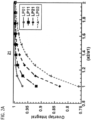
- FIG. 2A shows a graph 21 in which the overlap integrals for the fundamental mode LP 01 and three higher-order modes LP 11 , LP 21 , and LP 02 are plotted as a function of a 2 / a 1 (i.e., the active region radius a 2 normalized to the core radius a 1 ).
- the V-number, defined as 2 ⁇ a 1 ( NA )/ ⁇ is assumed to be 5.0 at the signal wavelength, supporting the four selected modes.
- Graph 21 further shows that as the radius of the rare-earth-doped region a 2 increases relative to the core radius a 1 , the difference between the respective overlap integrals decreases.
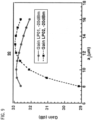
- FIG. 2B shows a graph 22 in which the small-signal gain, gain difference, and noise figure (NF) for the LP 01 and LP 02 modes, measured in decibels (dB), are plotted as a function of pump power, measured in milliwatts (mW).
- the core is assumed to have a diameter of 16 ⁇ m and a V-number of 5.0.
- the length of the gain fiber is 6 m and doping concentration of erbium is assumed to be 6.9 ⁇ 10 24 /m 3 .
- a Gaussian pump at 980 nm is assumed.
- An aspect of the invention is directed to a few-mode rare-earth-doped amplifier fiber that, in conjunction with a suitable pump source, equalizes gain for all of the modes supported by the core.
- FIG. 3 shows a cross section diagram (not drawn to scale) of a fiber 30 according to a practice of the invention.
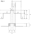
- FIG. 4 shows the fiber's refractive index profile 40 and rare-earth dopant distribution 45. Both the refractive index profile 40 and the dopant distribution 45 comprise a series of steps that define the following concentric fiber regions:
- the fiber regions are created by adding suitable chemical dopants to a substrate fabricated from silica or other suitable material.
- the index difference of the core 31 relative to the outer cladding 34 is equal to the core refractive index n 1 minus the refractive index of the outer cladding n 0 or, alternatively, the sum of ⁇ n 1 and ⁇ n 2 .
- n 1 - n 2 ⁇ n 1 + ⁇ n 2 .
- Fiber 30 is configured to provide an inner waveguide and an outer waveguide.
- the inner waveguide is formed by the boundary between the core 31 and inner cladding 33, and is configured to support the transmission of signal light at a selected wavelength in the fundamental mode LP 01 and the higher-order LP 11 , LP 21 , and LP 02 modes.
- the outer waveguide is formed by the boundary between the inner cladding 33 and the outer cladding 34, and is configured to guide a multimode pump light that is used to amplify signal light transmitted by the inner waveguide.
- FIG. 4 further shows an exemplary maximum optical field radius w 0 for the four supported modes.
- optical mode-field radius is defined as a radius where the field intensity for a given mode drops to a predefined fraction of the peak field intensity. (For the fundamental LP 01 mode, which has a Gaussian shape, the predefined fraction is typically 1/e.) Since the optical field profiles are different for different modes, the mode-field radius w 0 is also different for different modes. Generally, the mode-field radius w 0 is larger for modes with a larger mode number.
- the exemplary optical field radius w 0 is greater than the core radius a 1 .
- Active region 32 has a radius a 2 that is equal to, or greater than, the optical field radius w 0
- the inner cladding has an outer radius a 3 that is equal to, or greater than, the radius a 2 of the rare-earth-doped active region 32.
- the pump guiding region is highly multi-moded so that pump distribution can be considered uniform throughout the pump region, including the region doped with rare-earth ions.
- the rare-earth doped region 32 (corresponding to center step 46 in dopant distribution 45) has an inner portion 46a that encompasses the entire core region 31 and an outer portion 46b (shaded portion of dopant distribution 45) that surrounds the core 31 and extends into the inner cladding 33. It will be seen that the inner portion of the rare-earth doped region 46a has a refractive index equal to that of the core and that the outer portion of the rare-earth doped region 46b has a refractive index equal to that of the inner cladding.
- fiber 30 has an active region 32 that is large enough to encompass the optical field of the supported modes, while maintaining the core radius 31 that is necessary to support the selected transmission modes.
- Fiber 30 is configured to provide a highly multimoded outer waveguide for guiding a multimode pump light.
- dP m , n dz z ⁇ 0 a 2 ⁇ 0 2 ⁇ ⁇ s e N 2 ⁇ ⁇ s a N 1 p m , n r ⁇ rd ⁇ dr
- P m,n is the power of the LP m,n mode.
- Equation (4) therefore, indicates that small-signal gain becomes independent of mode type LP m,n .
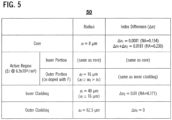
- FIG. 5 shows a table 50 setting forth specific values for the above-described EDF design parameters in an exemplary implementation.
- the V-number (2 ⁇ a ⁇ NA / ⁇ ) is equal to 5.0, which supports four modes: the fundamental LP 01 mode and the higher-order LP 11 , LP 21 , and LP 02 modes.
- the V-number is 17.5 and the number of modes supported by the pump-guiding region is 153. Pump radiation with such a large number of modes can make the field distribution essentially uniform.
- the mode number will vary in proportion to the square of the radius a 3 .
- Numerical simulation techniques can be used to model the performance of fiber 30 using the values setting forth in table 50.
- the fiber is assumed to have uniform erbium doping with a concentration of (6.89 ⁇ 10 24 )/m 3 .
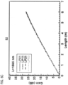
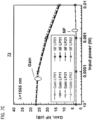
- FIGS. 6A-6C show a series of three graphs 61, 62, 63 illustrating the calculated gain for four different modes LP 10 , LP 11 , LP 21 , and LP 02 as a function of fiber length, at three signal wavelengths within the C-band: 1530 nm ( FIG. 6A , graph 61), 1550 nm ( FIG. 6B , graph 62), and 1565 nm ( FIG. 6C , graph 63).
- the input signal power is assumed to be -20 dBm
- the pump power level is assumed to be 1.24 mW/ ⁇ m 2 , which corresponds to 1 W for an inner cladding diameter (2 ⁇ a 3 ) of 32 ⁇ m.
- Graphs 61-63 illustrate the small the differences between the respective curves for the four supported modes at the three signal wavelengths.
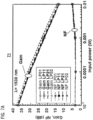
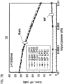
- FIGS. 7A-7C show a series of three graphs 71, 72, 73 showing the calculated values for gain and noise figure (NF) as a function of input signal power for the LP 01 , LP 11 , LP 21 and LP 02 modes at wavelengths of 1530 nm ( FIG. 7A , graph 71), 1550 nm ( FIG. 7B , graph 72), and 1565 nm ( FIG. 7C , graph 73).
- the length of the gain fiber is assumed to be 6 meters, and intensity of the 980 nm pump input is assumed to be 1.24 mW/ ⁇ m 2 , which corresponds to 1 W for a 32- ⁇ m inner cladding.
- the modal gain difference is found to be less than 2 dB for a wide range of input signal powers.
- the calculated NF is about 4 dB for input signal power of 1 mW.
- FIGS. 8A and 8B show a pair of graphs 81, 82 illustrating calculated gain and NF for the four supported modes as a function of launched pump power, with the signal power held constant at -20 dBm ( FIG. 8A , graph 81) and 0 dBm in ( FIG. 8B , graph 82).
- the length of gain fiber is again assumed to be 6 meters. For weak input signals the gain observed by different modes are almost the same. For stronger input signals, however, the differential gain increases to about 2 dB as the pump intensity is raised to 1.5 mW/ ⁇ m 2 .
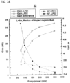
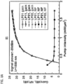
- FIG. 9 shows a graph 90 illustrating calculated gain for the LP 01 and LP 02 modes as a function of the radius of rare-earth-doped region a 2 .
- the input signal power is assumed to be -20 dBm, and the pump intensity is assumed to be 1.24 mW/ ⁇ m 2 .
- the gain for LP 01 and LP 02 signal modes have also been calculated for an erbium-doped region with different radii, varying within the range of 8 ⁇ m to 16 ⁇ m, under the assumption of uniform pump intensity distribution.
- the differential in gain is around 3 dB, and decreases with an increase in the size of the rare-earth-doped region.
- the differential gain can be kept below 1 dB when radius of rare-earth-doped region is increased to 10 ⁇ m 16 ⁇ m, i.e., 25% to 100% larger than the core size.
- Gain of the two modes become equal when the active region radius a 2 is approximately 11.5 ⁇ m.
- Matching the doping profile with power distribution can minimize population inversion in regions where is no signal, and thereby suppress spontaneous emission noise.
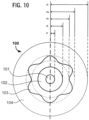
- FIG. 10 shows a cross-section diagram of a gain-equalized few-mode fiber 100 according to a further aspect of the invention, comprising a core 101 with a radius of a1, a rare-earth-doped active region 102 with a radius of a2, an inner cladding 103 with a radius that varies between a minimum radius a3i and an outer radius a3o, and an outer cladding 104 with radius a4.
- the boundary between the inner cladding 103 and the outer cladding 104 provides an outer waveguide for guiding pump radiation.
- this boundary is corrugated or star-shaped. The depicted configuration facilitates mode-mixing and in maintaining a uniform pump intensity distribution.
- the above-described techniques are applied in the context of a multicore fiber.
- FIG. 11 shows a cross-section schematic of a few-moded multicore fiber (MCF) 110 according to this aspect of the invention.
- MCF 110 comprises a central few-mode core 111a and six outer few-mode cores 111b arranged in a regular hexagonal array around the central core 111a.
- Each individual core 111a, 111b is provided with a respective rare-earth-doped region 112 having a radius that is sufficiently large to encompass the optical field of all of the modes supported by each core.
- all seven cores 111a, 111b and their respective active regions 112 are enclosed by a common star-shaped inner cladding 113.
- the boundary between the inner cladding and the outer cladding 114 provides a pump light waveguide that is shared by all seven cores 111a, 111b.
- a few-mode rare-earth-doped fiber in accordance the invention is fabricated using a modified chemical vapor deposition (MCVD) technique.
- MCVD modified chemical vapor deposition
- An aerosol or other vapor phase deposition technique is used to deposit layers of chemical soot onto the interior wall of a silica tube that is subsequently sintered and collapsed to form a cylindrical preform. The preform is then loaded into a draw tower and drawn into fiber.
- the core region can be doped, for example, with erbium and co-doped with aluminum (Al) in order to prevent concentration quenching.
- Al aluminum
- Fluorine dopant, boron dopant, or a combination of fluorine and boron dopants, may be added in order to allow a higher concentration of aluminum dopant in the fiber's pedestal region.
- FIG. 12 shows a flowchart of a general method 120 according to the above-described aspects of the invention.
- Method 120 comprises the following steps:
- the fiber may be configured to have a cladding that includes an inner cladding surrounding the core and an outer cladding surrounding the inner cladding, wherein the inner cladding and the outer cladding are configured to have an index difference ⁇ n 2 therebetween so as to provide a pump waveguide that supports a multimode pump light, and wherein the inner cladding has an outer radius a3, greater than or equal to the radius of the active region a 2 .
- the fiber may be configured to have a star-shaped outer waveguide, or to have a plurality of few-moded signal cores.
Landscapes
- Physics & Mathematics (AREA)
- Electromagnetism (AREA)
- Engineering & Computer Science (AREA)
- Plasma & Fusion (AREA)
- Optics & Photonics (AREA)
- Lasers (AREA)
- Optical Fibers, Optical Fiber Cores, And Optical Fiber Bundles (AREA)
Description
- The present invention relates generally to the field of fiber optical communications, and in particular to optical fiber amplifiers and amplification techniques.
- Few-mode rare-earth-doped fiber amplifiers provide gain to the fundamental (LP01) mode and a relatively small number of higher-order LP m , n modes, and are critical components in space-division-multiplexed optical transmission systems based on few-mode transmission fibers. Such systems have the potential of greatly enhancing transmission capacity and thus have recently attracted a great deal of interest.
- A prior-art fiber amplifier for use in single-mode transmission typically has a step refractive-index profile, comprising a core for guiding a fundamental mode (LP01) optical signal. A prior-art amplifier fiber further includes a rare-earth-doped region having a radius that is the same or slightly smaller than the core radius. A suitable pump source is used to provide pump radiation to the rare-earth-doped region.
- Transmission of light signals at higher-order modes requires a core that is larger than that of a single-mode fiber amplifier. However, an increase in core size results in significant gain differences among the supported transmission modes. Gain equalization is thus a significant issue to be addressed in the development of few-mode optical fiber amplifiers. In addressing this issue, a few-mode optical fiber amplifier design should also take into consideration the overall complexity and cost of the design.
- A first practice of the invention provides a few-mode rare-earth-doped amplifier fiber with equalized gain. The fiber has a raised-index core surrounded by a lower-index cladding. The core has a radius a 1 and an index difference Δn1 relative to the surrounding cladding and is configured to support, at a selected signal wavelength, a set of lower-order fiber modes having an optical field with a diameter greater than 2·a 1. The fiber further includes an active region, doped with a rare-earth dopant, comprising an inner portion that is coextensive with the core and an outer portion that surrounds the inner portion and extends into the cladding. The active region has an outer radius a 2 greater than a 1 that encompasses the optical field of the set of lower-order fiber modes at the selected signal wavelength.
- In a further practice of the invention, the few-mode rare-earth-doped amplifier fiber is provided with an inner few-mode waveguide for transmitting signals in a number of selected modes, and a multimoded outer waveguide for guiding pump light from a suitable pump source.
-
-
FIG. 1 shows a cross-section diagram of an exemplary few-mode amplifier fiber. -
FIG. 2A shows a graph in which the overlap integrals for the modes supported by the fiber shownFIG. 1 are plotted as a function of the radius of the active region normalized to the core radius;FIG. 2B shows a graph in which the small-signal gain, gain difference, and noise figure for the supported modes are plotted as a function of pump power. -
FIG. 3 shows a cross section diagram of an exemplary few-mode amplifier fiber according to an aspect of the invention. -
FIG. 4 shows the refractive index profile and rare-earth dopant distribution for the few-mode amplifier fiber shown inFIG. 3 . -
FIG. 5 shows a table setting forth specific values for an exemplary implementation of the few-mode fiber amplifier shown inFIG. 4 . -
FIG. 6A-6C ,7A-7C ,8A-8B , and9 show a series of graphs illustrating the calculated modal gain for an exemplary few-mode fiber amplifier incorporating the values set forth in the table shown inFIG. 5 . -
FIG. 10 shows a cross-section schematic of a few-moded fiber amplifier incorporating a star-shaped outer waveguide according a further aspect of the invention. -
FIG. 11 shows a cross-section schematic of a few-moded fiber amplifier having seven cores, in accordance with a further aspect of the invention. -
FIG. 12 shows a flowchart of a general method according to the above-described aspects of the invention. - Aspects of the recent invention are directed to a few-mode fiber amplifier and amplification techniques that are inherently capable of providing equal gain to all the modes supported by the core, and that allow operation over a wide range of pump powers.
- One practice of the invention is directed to a few-mode, rare-earth-doped fiber having (a) a core that supports, at a selected signal wavelength (or a selected range of signal wavelengths), the fundamental LP01 mode and a selected set of higher-order LP m,n modes; and (b) a rare-earth-doped active region that is large enough to encompass the optical field of the supported modes.
- As discussed below, in a few-mode amplifier fiber, unequal portions of the respective optical fields of the supported modes extend beyond core radius. In a few-mode amplifier fiber in which the active region is the same size as the core, the modal gains are not equal because of the inequality of the overlap integrals Γ between the active region and the respective intensity profiles of the supported modes.
- According to an aspect of the invention, modal gains are equalized in a few-mode rare-earth-doped amplifier fiber by chemically doping the fiber to provide a rare-earth-doped region that is large enough to encompass the optical fields of all of the selected higher-order modes, while at the same time maintaining a core radius that supports transmission in the selected modes. As discussed below, the rare-earth-doped active region encompassing the entire core and an outer portion that surrounds, and extends beyond, the core. Suitable rare-earth dopants for the active region include, for example: erbium (Er), ytterbium (Yb), neodymium (Nd), thulium (Tm), and the like, by themselves, in combination with each other, or in combination with other suitable dopants.
- In a further practice of the invention, the above-described few-mode, rare-earth-doped fiber is configured to include a pump light waveguide having a radial extent that encompasses at least the rare-earth-doped active region. According to an aspect of the invention, the pump light is multimoded, and is configured to provide uniform population inversion across the active region so as to equalize gain for different signal transmission modes.
- There is now discussed the theoretical foundation of the invention, followed by a description of a number of exemplary practices.
- The small-signal gain, g, per unit length of a gain medium is the gain obtained for an input signal that is small enough to prevent gain saturation. For a conventional erbium-doped fiber having an active region that is uniformly doped with erbium, wherein the active region has a radius R that is less than the fiber radius, the small-signal gain, g, can be expressed by the following Equation (1):

- N 1 = population of the lower state of the laser/amplifier transition;
- N 2 = population of the upper state of the laser/amplifier transition;
-

-

- Γ = overlap factor.
- The overlap factor Γ (also known as the "overlap integral" or "overlap integral factor"), accounts for the proportion of the optical signal power propagating through the rare-earth-doped region, and can be expressed by the following Equation (2):

- In (r, θ) = normalized transverse mode intensity profile of the signal; and
- R = radius of the equivalent flat top distribution of the rare-earth-doped region.
- In a rare-earth-doped fiber having a core that supports a selected few higher-order LP m,n modes, the overlap integral Γ is different for the different modes. This difference in Γ in turn results in modal gain differences that vary as a function of the core radius and the radius of the active region.
- Equations (1) and (2) are now discussed with respect to an exemplary few-mode rare-earth-doped fiber.
-
FIG. 1 shows a cross-section diagram of theexemplary fiber 10, which comprises a few-mode core 11 with radius a 1, a rare-earth-dopedactive region 12 with radius a 2, and acladding region 14. Core 11 is configured to support four transmission modes: the fundamental mode LP01 and the higher-order LP11, LP21, and LP02 modes. For the purposes of illustration, a set ofgraphs 15 of the respective intensity distributions of the four modes are shown at the top ofFIG. 1 in alignment with the cross section offiber 10. - As shown in
FIG. 1 , theoptical field 16 of the four modes has an outer radius w0 that is larger than the core radius a 1 . (It is noted that, unless indicated otherwise either explicitly or by context, the term "optical field" refers generally to the optical fields of the supported modes of a few-mode fiber.) As noted above, the four depicted modes have varying portions extending outside of the core. - For the purposes of the present discussion, the active region radius a 2 is treated as a variable, and the core radius a 1 and the optical field radius w0 are constants for a given fiber design at the wavelength of interest. From Equations (1) and (2), discussed above, it will be seen that the respective overlap integrals for each of the supported modes varies as a function of the radius a 2 of rare-earth doped
region 12. -
FIG. 2A shows agraph 21 in which the overlap integrals for the fundamental mode LP01 and three higher-order modes LP11, LP21, and LP02 are plotted as a function of a 2/a 1 (i.e., the active region radius a 2 normalized to the core radius a 1). The values for a 2/a 1 range from 1.0 (i.e., a 2=a 1) to 2.0 (i.e., a 2=2·a 1). The V-number, defined as 2πa 1 (NA)/λ, is assumed to be 5.0 at the signal wavelength, supporting the four selected modes. -
Graph 21 shows that when the doped region and the core region are of the same size (a 2 la 1=1), the higher-order modes (i.e., the LP11, LP21, and LP02 modes) exhibit a much smaller overlap integral in comparison with the fundamental mode LP01.Graph 21 further shows that as the radius of the rare-earth-doped region a 2 increases relative to the core radius a 1 , the difference between the respective overlap integrals decreases. - Pump power is another factor to be considered.
FIG. 2B shows a graph 22 in which the small-signal gain, gain difference, and noise figure (NF) for the LP01 and LP02 modes, measured in decibels (dB), are plotted as a function of pump power, measured in milliwatts (mW). The core is assumed to have a diameter of 16 µm and a V-number of 5.0. The length of the gain fiber is 6 m and doping concentration of erbium is assumed to be 6.9×1024/m3. A Gaussian pump at 980 nm is assumed. - As illustrated in graph 22, the gain in the LP02-moded signal can be lower than the gain for the LP01 mode by as much as 5 dB when the erbium dopant is located within the high-index core region, i.e., a 2=a 1 .
- An aspect of the invention is directed to a few-mode rare-earth-doped amplifier fiber that, in conjunction with a suitable pump source, equalizes gain for all of the modes supported by the core.
-
FIG. 3 shows a cross section diagram (not drawn to scale) of afiber 30 according to a practice of the invention.FIG. 4 shows the fiber'srefractive index profile 40 and rare-earth dopant distribution 45. Both therefractive index profile 40 and thedopant distribution 45 comprise a series of steps that define the following concentric fiber regions: - (1) A raised-
index core 31, corresponding tocentral spike 41 inindex profile 40, having a radius a 1 and a refractive index n1. - (2) A rare-earth-doped
active region 32 extending between r = 0 and r = a 2 (where a 2 > a 1), corresponding to centerstep 46 indopant profile 45, and having a rare-earth-dopant concentration of N. - (3) A raised-index
inner cladding 33, corresponding topedestal 43 inindex profile 40, having a radius a 3 and a refractive index n2. - (4) An undoped
outer cladding 34, corresponding to the flatouter portion 44 inindex profile 40, having a radius a 4 and a refractive index n0. - As discussed below, the fiber regions are created by adding suitable chemical dopants to a substrate fabricated from silica or other suitable material.
- For the purposes of the present discussion, the respective refractive index of each of the fiber regions is discussed with respect to its nominal refractive index:
core 31 has an index difference Δn1, relative to the refractive index n2 of inner cladding 33 (i.e., Δn1 = n1 - n2);inner cladding 33 has an index difference Δn2, relative to the index n0 of outer cladding 34 (i.e., Δn2 = n2 - n0); andouter cladding 34 an index difference Δn0 = n0 - n0 = 0. (The index difference of the core 31 relative to theouter cladding 34 is equal to the core refractive index n1 minus the refractive index of the outer cladding n0 or, alternatively, the sum of Δn1 and Δn2. In other words, n1 - n2 = Δn1 + Δn2.) -
Fiber 30 is configured to provide an inner waveguide and an outer waveguide. The inner waveguide is formed by the boundary between the core 31 andinner cladding 33, and is configured to support the transmission of signal light at a selected wavelength in the fundamental mode LP01 and the higher-order LP11, LP21, and LP02 modes. The outer waveguide is formed by the boundary between theinner cladding 33 and theouter cladding 34, and is configured to guide a multimode pump light that is used to amplify signal light transmitted by the inner waveguide. -
FIG. 4 further shows an exemplary maximum optical field radius w0 for the four supported modes. Generally speaking, optical mode-field radius is defined as a radius where the field intensity for a given mode drops to a predefined fraction of the peak field intensity. (For the fundamental LP01 mode, which has a Gaussian shape, the predefined fraction is typically 1/e.) Since the optical field profiles are different for different modes, the mode-field radius w0 is also different for different modes. Generally, the mode-field radius w0 is larger for modes with a larger mode number. - As shown in
FIG. 4 , the exemplary optical field radius w0 is greater than the core radius a 1.Active region 32 has a radius a 2 that is equal to, or greater than, the optical field radius w0, and the inner cladding has an outer radius a 3 that is equal to, or greater than, the radius a 2 of the rare-earth-dopedactive region 32. The pump guiding region is highly multi-moded so that pump distribution can be considered uniform throughout the pump region, including the region doped with rare-earth ions. - As further shown in
FIG. 4 , the rare-earth doped region 32 (corresponding to centerstep 46 in dopant distribution 45) has aninner portion 46a that encompasses theentire core region 31 and anouter portion 46b (shaded portion of dopant distribution 45) that surrounds thecore 31 and extends into theinner cladding 33. It will be seen that the inner portion of the rare-earth dopedregion 46a has a refractive index equal to that of the core and that the outer portion of the rare-earth dopedregion 46b has a refractive index equal to that of the inner cladding. - As discussed below, one way to achieve the above-described configuration is to dope the core 31, which is co-extensive with the rare-earth doped
inner region 46a, with an index-raising rare-earth dopant, and to co-dope the outer portion of the rare-earth-dopedregion 46b with the same rare-earth dopant and an index-lowering dopant, such as fluorine (F). Thus,fiber 30 has anactive region 32 that is large enough to encompass the optical field of the supported modes, while maintaining thecore radius 31 that is necessary to support the selected transmission modes. -
Fiber 30 is configured to provide a highly multimoded outer waveguide for guiding a multimode pump light. - When the intensity of pump field launched into the outer waveguide is sufficiently high, a uniform population inversion can be established entirely over the rare-earth-doped region. For small-signals propagating with LP m,n mode, the gain per unit length that can be expressed as:


- For a uniform population inversion maintained across the entirety of rare earth doped region, the bracketed term in Eq. (3) becomes independent of the radius, such that the equation can be expressed as:

- Equation (4), therefore, indicates that small-signal gain becomes independent of mode type LP m,n.
-
FIG. 5 shows a table 50 setting forth specific values for the above-described EDF design parameters in an exemplary implementation. - As set forth in table 50, the exemplary fiber has a core radius of 8 µm (a 1=8µm), a nominal refractive index difference of 0.0081 (NA=0.154) relative to the inner cladding, and a nominal refractive index difference of 0.0181 (NA=0.230) relative to the outer cladding. For a signal in the 1550 nm region, the V-number (2πa·NA/λ) is equal to 5.0, which supports four modes: the fundamental LP01 mode and the higher-order LP11, LP21, and LP02 modes. The rare-earth-doped region has a radius of 16 µm (i.e., a 2=16 µm), and encompasses the entire core. The region guiding the pump has a nominal index difference of 0.01 (NA=0.171) and has a radius that is 16 µm or more (i.e., a 2 ≤ a 3).
- In a special case, the fiber is configured to have a pump region with the same size as the doped region, i.e., a 2=a 3 . For a 980 nm pump, the V-number is 17.5 and the number of modes supported by the pump-guiding region is 153. Pump radiation with such a large number of modes can make the field distribution essentially uniform. For a pump-guiding region having a larger diameter, the mode number will vary in proportion to the square of the radius a 3.
- Numerical simulation techniques can be used to model the performance of
fiber 30 using the values setting forth in table 50. The gain and noise figure are calculated numerically from the radial and azimuthal distribution of the upper and lower state population, N2 and N1, which are shown in the following:
- The fiber is assumed to have uniform erbium doping with a concentration of (6.89 × 1024)/m3.
-
FIGS. 6A-6C show a series of threegraphs FIG. 6A , graph 61), 1550 nm (FIG. 6B , graph 62), and 1565 nm (FIG. 6C , graph 63). The input signal power is assumed to be -20 dBm, and the pump power level is assumed to be 1.24 mW/µm2, which corresponds to 1 W for an inner cladding diameter (2·a 3) of 32 µm. Graphs 61-63 illustrate the small the differences between the respective curves for the four supported modes at the three signal wavelengths. -
FIGS. 7A-7C show a series of threegraphs FIG. 7A , graph 71), 1550 nm (FIG. 7B , graph 72), and 1565 nm (FIG. 7C , graph 73). The length of the gain fiber is assumed to be 6 meters, and intensity of the 980 nm pump input is assumed to be 1.24 mW/µm2, which corresponds to 1 W for a 32-µm inner cladding. As shown in graphs 71-73, the modal gain difference is found to be less than 2 dB for a wide range of input signal powers. The calculated NF is about 4 dB for input signal power of 1 mW. -
FIGS. 8A and8B show a pair ofgraphs FIG. 8A , graph 81) and 0 dBm in (FIG. 8B , graph 82). The length of gain fiber is again assumed to be 6 meters. For weak input signals the gain observed by different modes are almost the same. For stronger input signals, however, the differential gain increases to about 2 dB as the pump intensity is raised to 1.5 mW/µm2. -
FIG. 9 shows agraph 90 illustrating calculated gain for the LP01 and LP02 modes as a function of the radius of rare-earth-doped region a 2. The core radius is assumed to be 8 µm (V=5.0). The input signal power is assumed to be -20 dBm, and the pump intensity is assumed to be 1.24 mW/µm2. - The gain for LP01 and LP02 signal modes have also been calculated for an erbium-doped region with different radii, varying within the range of 8 µm to 16 µm, under the assumption of uniform pump intensity distribution. When the core rare earth doped region has a radius of 8 µm, i.e., the same as the core, the differential in gain is around 3 dB, and decreases with an increase in the size of the rare-earth-doped region. The differential gain can be kept below 1 dB when radius of rare-earth-doped region is increased to 10
µm 16 µm, i.e., 25% to 100% larger than the core size. Gain of the two modes become equal when the active region radius a 2 is approximately 11.5 µm. - Moreover, it should be recognized while a uniform doping distribution is desirable, some variations from nominal uniform distribution may exist. These variations may arise, for example, as a result of fabrication difficulties and may also depend upon the particular processes by which the fiber preforms are fabricated.
- In the above analyses, the erbium dopant concentration is assumed to be uniform within the erbium-doped region, a 2 . It is possible to reduce the width of rare-earth doped region by matching the rare-earth dopant distribution with the sum of optical power distributions pm,n in different lower-order modes. For example, one can tailor the rare-earth dopant distribution proportional to the following:

- Matching the doping profile with power distribution can minimize population inversion in regions where is no signal, and thereby suppress spontaneous emission noise.
-
FIG. 10 shows a cross-section diagram of a gain-equalized few-mode fiber 100 according to a further aspect of the invention, comprising acore 101 with a radius of a1, a rare-earth-dopedactive region 102 with a radius of a2, aninner cladding 103 with a radius that varies between a minimum radius a3i and an outer radius a3o, and anouter cladding 104 with radius a4. - As in
fiber 30, discussed above, the boundary between theinner cladding 103 and theouter cladding 104 provides an outer waveguide for guiding pump radiation. Infiber 100, this boundary is corrugated or star-shaped. The depicted configuration facilitates mode-mixing and in maintaining a uniform pump intensity distribution. - According to a further aspect of the invention, the above-described techniques are applied in the context of a multicore fiber.
-
FIG. 11 shows a cross-section schematic of a few-moded multicore fiber (MCF) 110 according to this aspect of the invention. -
MCF 110 comprises a central few-mode core 111a and six outer few-mode cores 111b arranged in a regular hexagonal array around thecentral core 111a. Eachindividual core region 112 having a radius that is sufficiently large to encompass the optical field of all of the modes supported by each core. In the depicted example, all sevencores active regions 112 are enclosed by a common star-shapedinner cladding 113. The boundary between the inner cladding and theouter cladding 114 provides a pump light waveguide that is shared by all sevencores - In an exemplary practice, a few-mode rare-earth-doped fiber in accordance the invention is fabricated using a modified chemical vapor deposition (MCVD) technique. An aerosol or other vapor phase deposition technique is used to deposit layers of chemical soot onto the interior wall of a silica tube that is subsequently sintered and collapsed to form a cylindrical preform. The preform is then loaded into a draw tower and drawn into fiber.
- In one practice of the invention, the core region has the following respective index difference values Δn for the core and inner cladding relative to the outer cladding:
core relative to inner cladding Δn1 = 0.0081 NA = 0.154 inner cladding relative to outer cladding Δn2 = 0.0100 NA = 0.171 core relative to outer cladding Δn1+Δn2 = 0.0181 NA = 0.230 - (These values are also set forth in table 50, shown in
FIG. 5 .) The core region can be doped, for example, with erbium and co-doped with aluminum (Al) in order to prevent concentration quenching. Fluorine dopant, boron dopant, or a combination of fluorine and boron dopants, may be added in order to allow a higher concentration of aluminum dopant in the fiber's pedestal region. -
FIG. 12 shows a flowchart of ageneral method 120 according to the above-described aspects of the invention.Method 120 comprises the following steps: - 121: Configure an optical fiber to have a raised-index core surrounded by a lower index cladding, wherein the raised-index core has a radius a 1 and an index difference Δn1 relative to the cladding that are configured to provide a waveguide to support, at a selected signal wavelength, a set of lower-order fiber modes having an optical field with a diameter greater than 2·a 1.
- 122: Configure the fiber to have a rare-earth doped active region with an outer radius a 2, comprising an inner portion that is coextensive with the core and an outer portion that surrounds the inner portion and extends into the cladding, wherein the outer portion of the active region has a refractive index equal to that of the cladding surrounding the core.
- 123: Configure the outer portion of the active region to have an outer radius a 2, greater than a 1, that encompasses the optical field of the set of lower-order fiber modes at the selected signal wavelength.
- As discussed above, according to an aspect of the invention, the fiber may be configured to have a cladding that includes an inner cladding surrounding the core and an outer cladding surrounding the inner cladding, wherein the inner cladding and the outer cladding are configured to have an index difference Δn2 therebetween so as to provide a pump waveguide that supports a multimode pump light, and wherein the inner cladding has an outer radius a3, greater than or equal to the radius of the active region a 2.
- According to further aspects of the invention discussed above, the fiber may be configured to have a star-shaped outer waveguide, or to have a plurality of few-moded signal cores.
- While the foregoing description includes details that will enable those skilled in the art to practice the invention, it should be recognized that the description is illustrative in nature and that many modifications and variations thereof will be apparent to those skilled in the art having the benefit of these teachings. It is accordingly intended that the invention herein be defined solely by the claims appended hereto.
Claims (12)
- A gain-equalized few-mode fiber amplifier, comprising:a fiber, comprising:a raised-index core (31) having a radius a 1 = 8µm;a raised-index cladding (33) surrounding the raised-index core (31), the raised-index cladding (33) having an outer radius a 3 ≥ 16µm,the raised-index cladding (33) having an index difference Δn1 = 0.0081 relative to the raised-index core (31); anda rare-earth doped active region (32) having a radius a 2 = 16µm, the rare-earth doped active region (32) configured to support a set of lower-order fiber modes at a selected signal wavelength, the rare-earth doped active region (32) further configured to provide equalized gain across the set of lower-order fiber modes, the set of lower-order fiber modes having an optical field radius w 0, the rare-earth doped active region (32) comprising:an inner portion (46a) encompassing the raised-index core (31); andan outer portion (46b) that extends partially into the raised-index inner cladding (33); andwherein a 3 ≥ a 2 ≥ w 0 > a 1.
- The fiber amplifier of claim 1, wherein the set of lower-order fiber modes comprises a plurality of modes selected from the LP01, LP11, LP21, and LP02 modes.
- The fiber amplifier of claim 2,
wherein the rare-earth doped active region (32) has a dopant concentration that is essentially uniform throughout the active region. - The fiber amplifier of claim 1,
wherein the rare-earth doped active region (32) has a dopant concentration that is nonuniform within the active region. - The fiber amplifier of claim 4,
wherein the rare-earth dopant concentration has a radial profile that is proportional to a sum of optical power radial distribution profiles of the set of lower order fiber modes. - The fiber amplifier of claim 1,wherein the raised-index core (31) is doped with a rare-earth dopant, andwherein the outer portion (46b) of the rare-earth doped active region (32) is co-doped with the rare-earth dopant and an index-lowering dopant.
- The fiber amplifier of claim 6,
wherein the index-lowering dopant is fluorine or boron or a combination of fluorine and boron. - The fiber amplifier of claim 1,
wherein the rare-earth doped active region (32) is doped with one or more dopants selected from a group consisting of erbium, ytterbium, neodymium, thulium, praseodymium, and holmium. - The fiber amplifier of claim 1, further comprising a cladding, wherein the cladding comprises the raised-index inner cladding (33) and a lower-index outer cladding (34), wherein the lower-index outer cladding (34) is configured to provide a pump waveguide for a pump light input into the fiber, wherein the raised-index inner cladding (33) has an index difference Δn2 relative to the outer cladding (34), and wherein the raised-index inner cladding (33) extends across the rare-earth doped active region (32).
- The fiber amplifier of claim 9, wherein Δn2 is 0.0100.
- A gain-equalized few-mode, multicore fiber amplifier, comprising:
a multicore fiber (110), comprising:raised-index cores (111a, 111b) each having a radius a 1 = 8µm ;a common raised-index cladding (113) surrounding the raised-index cores (111a, 111b), the common raised-index cladding (113) having an index difference = 0.0081 relative to the raised-index cores (111a, 111b); andrare-earth doped active regions (112) each having a radius a2 = 16µm, each rare-earth doped active regions (112) configured to support a set of lower-order fiber modes at a selected signal wavelength, each rare-earth doped active regions (112) further configured to provide equalized gain across the set of lower-order fiber modes, the set of lower-order fiber modes having an optical field radius w 0, each rare-earth doped active regions (112) comprising:an inner portion encompassing its respective raised-index core (111a, 111b); andan outer portion that extends partially into the common raised-index inner cladding (113); andwherein a 2 ≥ w0 > a 1. - The multicore fiber of claim 11, further comprising a cladding, wherein the cladding comprises the common raised-index inner cladding (113) and a lower-index outer cladding (114), wherein the lower-index outer cladding (114) is configured to provide a waveguide for a pump light input into the fiber (110), wherein the common raised-index inner cladding (113) has an index difference Δn2 relative to the outer cladding (114), and
wherein the common raised-index inner cladding (113) extends across all of the rare-earth doped active regions (112).
Applications Claiming Priority (2)
| Application Number | Priority Date | Filing Date | Title |
|---|---|---|---|
| US201361879329P | 2013-09-18 | 2013-09-18 | |
| US14/486,616 US9077148B2 (en) | 2013-09-18 | 2014-09-15 | Gain-equalized few-mode fiber amplifier |
Publications (3)
| Publication Number | Publication Date |
|---|---|
| EP2852011A2 EP2852011A2 (en) | 2015-03-25 |
| EP2852011A3 EP2852011A3 (en) | 2015-08-05 |
| EP2852011B1 true EP2852011B1 (en) | 2023-04-19 |
Family
ID=51542253
Family Applications (1)
| Application Number | Title | Priority Date | Filing Date |
|---|---|---|---|
| EP14185168.3A Active EP2852011B1 (en) | 2013-09-18 | 2014-09-17 | Gain-equalized few-mode fiber amplifier |
Country Status (3)
| Country | Link |
|---|---|
| US (1) | US9077148B2 (en) |
| EP (1) | EP2852011B1 (en) |
| JP (2) | JP2015061079A (en) |
Families Citing this family (17)
| Publication number | Priority date | Publication date | Assignee | Title |
|---|---|---|---|---|
| CN104793285B (en) * | 2015-04-29 | 2018-01-02 | 武汉邮电科学研究院 | Low-loss less fundamental mode optical fibre |
| US10761267B2 (en) | 2015-08-13 | 2020-09-01 | Nufem | Mode mixing optical fibers and methods and systems using the same |
| JP2017098296A (en) * | 2015-11-18 | 2017-06-01 | Kddi株式会社 | Optical amplifier |
| WO2017136831A1 (en) * | 2016-02-05 | 2017-08-10 | Nufern | Mode mixing optical fibers and methods and systems using the same |
| US10733944B2 (en) * | 2016-02-19 | 2020-08-04 | Signify Holding B.V. | Configurable modes for lighting systems |
| JP6571562B2 (en) * | 2016-03-03 | 2019-09-04 | 日本電信電話株式会社 | Amplifying optical fiber design method |
| WO2018071844A1 (en) * | 2016-10-14 | 2018-04-19 | The Government Of The United States Of America, As Represented By The Secretary Of The Navy | Nanoparticle doping for lasers and amplifiers operating at eye-safer wavelengths, and/or exhibiting reduced stimulated brillouin scattering |
| JP6663387B2 (en) * | 2017-05-08 | 2020-03-11 | 株式会社フジクラ | Multimode fiber, optical amplifier, and fiber laser |
| FR3068486B1 (en) * | 2017-07-03 | 2021-10-15 | Centre Nat Rech Scient | SLIGHTLY MULTIMODED AMPLIFIER FIBER |
| CN110277728A (en) * | 2019-06-26 | 2019-09-24 | 中国计量大学 | Passively mode-locked fiber laser based on saturable absorber in few-mode fiber |
| WO2021059443A1 (en) * | 2019-09-26 | 2021-04-01 | 日本電信電話株式会社 | Amplification fiber and optical amplifier |
| CN111123427B (en) * | 2020-01-20 | 2024-04-26 | 北京交通大学 | A step-index few-mode fiber with up-doped refractive index for modal gain equalization |
| CN112711091B (en) * | 2021-01-19 | 2022-02-01 | 北京交通大学 | Multi-core erbium-doped super-mode optical fiber for gain equalization |
| CN113703158B (en) * | 2021-09-07 | 2022-05-13 | 北京交通大学 | A fast design method for gain profile of few-mode fiber for inter-mode gain equalization |
| CN114268014B (en) * | 2022-03-01 | 2022-07-26 | 武汉长进激光技术有限公司 | Erbium-ytterbium co-doped few-mode optical fiber amplifier |
| US12567715B2 (en) * | 2022-08-25 | 2026-03-03 | Huawei Technologies Canada Co., Ltd. | Optical fiber amplifier for reducing differential modal gain of an optical fiber |
| CN119620507A (en) * | 2024-12-12 | 2025-03-14 | 吉林大学 | Concentration and refractive index coordinated control gain balanced optical waveguide amplifier and preparation method |
Family Cites Families (14)
| Publication number | Priority date | Publication date | Assignee | Title |
|---|---|---|---|---|
| JP2998247B2 (en) * | 1991-03-20 | 2000-01-11 | 富士通株式会社 | Erbium fiber for optical amplifier |
| US5187759A (en) * | 1991-11-07 | 1993-02-16 | At&T Bell Laboratories | High gain multi-mode optical amplifier |
| CA2182830C (en) * | 1996-02-22 | 2002-06-18 | Katsuyuki Imoto | Rare earth element-doped multiple-core optical fiber and optical systems using the same |
| JP4075113B2 (en) * | 1997-11-07 | 2008-04-16 | 住友電気工業株式会社 | Optical fiber amplifier and erbium-doped optical fiber |
| US20090052476A1 (en) * | 2007-08-07 | 2009-02-26 | Hitachi Cable, Ltd. | Optical fiber for an optical fiber laser, method for fabricating the same, and optical fiber laser |
| US8873134B2 (en) * | 2008-08-21 | 2014-10-28 | Nlight Photonics Corporation | Hybrid laser amplifier system including active taper |
| WO2010060435A1 (en) * | 2008-11-28 | 2010-06-03 | Nkt Photonics A/S | Improved cladding-pumped optical waveguide |
| JP5124701B1 (en) * | 2011-03-31 | 2013-01-23 | 株式会社フジクラ | Amplifying optical fiber, and optical fiber amplifier and resonator using the same |
| JP5727305B2 (en) * | 2011-06-13 | 2015-06-03 | 日本電信電話株式会社 | Optical fiber amplifier |
| JP5324012B2 (en) * | 2011-08-08 | 2013-10-23 | 古河電気工業株式会社 | Multi-core optical fiber and optical transmission system |
| JP2015510253A (en) * | 2011-12-13 | 2015-04-02 | オーエフエス ファイテル,エルエルシー | Multi-core erbium-doped fiber amplifier |
| US8848285B2 (en) * | 2012-01-12 | 2014-09-30 | Corning Incorporated | Few mode optical fibers for Er doped amplifiers, and amplifiers using such |
| US9197030B2 (en) * | 2012-07-31 | 2015-11-24 | Corning Incorporated | Few mode rare earth doped optical fibers for optical amplifiers, and amplifiers using such fibers |
| US9093815B2 (en) * | 2012-08-29 | 2015-07-28 | Ofs Fitel, Llc | Optical fiber amplifier including rare-earth-doped cladding region |
-
2014
- 2014-09-15 US US14/486,616 patent/US9077148B2/en active Active
- 2014-09-17 EP EP14185168.3A patent/EP2852011B1/en active Active
- 2014-09-18 JP JP2014189512A patent/JP2015061079A/en active Pending
-
2016
- 2016-11-24 JP JP2016227394A patent/JP2017059845A/en active Pending
Also Published As
| Publication number | Publication date |
|---|---|
| JP2017059845A (en) | 2017-03-23 |
| EP2852011A3 (en) | 2015-08-05 |
| US9077148B2 (en) | 2015-07-07 |
| US20150077837A1 (en) | 2015-03-19 |
| JP2015061079A (en) | 2015-03-30 |
| EP2852011A2 (en) | 2015-03-25 |
Similar Documents
| Publication | Publication Date | Title |
|---|---|---|
| EP2852011B1 (en) | Gain-equalized few-mode fiber amplifier | |
| US20220329035A1 (en) | Fiber amplifier | |
| EP2703854B1 (en) | Double-clad, gain-producting fibers with increased cladding absorption while maintaining single-mode operation | |
| US8428409B2 (en) | Filter fiber for use in Raman lasing applications and techniques for manufacturing same | |
| US7570856B1 (en) | Apparatus and method for an erbium-doped fiber for high peak-power applications | |
| US9197030B2 (en) | Few mode rare earth doped optical fibers for optical amplifiers, and amplifiers using such fibers | |
| US6751388B2 (en) | Fiber lasers having a complex-valued Vc-parameter for gain-guiding | |
| WO2013102033A1 (en) | Active tapers with reduced nonlinearity | |
| US9366806B2 (en) | Gain-producing fibers with increased cladding absorption while maintaining single-mode operation | |
| CN101657943A (en) | Rare-earth doped core multi-clad fiber, fiber amplifier, and fiber laser | |
| US12519279B2 (en) | Active lma optical fiber with enhanced transverse mode stability | |
| US8611002B2 (en) | Optical fiber lasers and amplifiers and methods for providing optical gain | |
| EP1865582B1 (en) | Optical fibre amplifier | |
| US8787721B2 (en) | Rare earth-doped fiber optic device for emitting or amplifying a signal in the “S” band | |
| Hotoleanu et al. | High-order modes suppression in large mode area active fibers by controlling the radial distribution of the rare earth dopant | |
| Kang et al. | Minimizing differential modal gain in cladding pumped MM-EDFAs for mode division multiplexing in C and L bands | |
| WO2014197052A2 (en) | Multi-core optical fibers | |
| Kang et al. | Modal gain control in a multimode erbium doped fiber amplifier incorporating ring doping | |
| Kamakshi et al. | Inherently gain flattened S-band erbium doped fiber amplifier based on dual core resonant leaky fiber | |
| Hougaard et al. | Amplifiers and lasers in PCF configurations | |
| Mondal et al. | Designing high performance Er+ 3-doped fiber amplifier in triangular-lattice photonic crystal fiber host towards higher gain, low splice loss | |
| CN121488178A (en) | LMA fiber having annular index reduction region in the inner core | |
| Ye et al. | Near-diffraction-limited output from confined-doped ytterbium fibre with 41 µm core diameter | |
| US20090238216A1 (en) | Rare-earth doped optical fiber, method of producing the same, and fiber laser | |
| JP2024147955A (en) | Optical amplifier and rare earth doped fiber |
Legal Events
| Date | Code | Title | Description |
|---|---|---|---|
| PUAI | Public reference made under article 153(3) epc to a published international application that has entered the european phase |
Free format text: ORIGINAL CODE: 0009012 |
|
| 17P | Request for examination filed |
Effective date: 20140917 |
|
| AK | Designated contracting states |
Kind code of ref document: A2 Designated state(s): AL AT BE BG CH CY CZ DE DK EE ES FI FR GB GR HR HU IE IS IT LI LT LU LV MC MK MT NL NO PL PT RO RS SE SI SK SM TR |
|
| AX | Request for extension of the european patent |
Extension state: BA ME |
|
| PUAL | Search report despatched |
Free format text: ORIGINAL CODE: 0009013 |
|
| AK | Designated contracting states |
Kind code of ref document: A3 Designated state(s): AL AT BE BG CH CY CZ DE DK EE ES FI FR GB GR HR HU IE IS IT LI LT LU LV MC MK MT NL NO PL PT RO RS SE SI SK SM TR |
|
| AX | Request for extension of the european patent |
Extension state: BA ME |
|
| RIC1 | Information provided on ipc code assigned before grant |
Ipc: H01S 3/094 20060101ALN20150629BHEP Ipc: H01S 3/067 20060101AFI20150629BHEP Ipc: H01S 3/16 20060101ALN20150629BHEP |
|
| R17P | Request for examination filed (corrected) |
Effective date: 20160203 |
|
| RBV | Designated contracting states (corrected) |
Designated state(s): AL AT BE BG CH CY CZ DE DK EE ES FI FR GB GR HR HU IE IS IT LI LT LU LV MC MK MT NL NO PL PT RO RS SE SI SK SM TR |
|
| STAA | Information on the status of an ep patent application or granted ep patent |
Free format text: STATUS: EXAMINATION IS IN PROGRESS |
|
| 17Q | First examination report despatched |
Effective date: 20180906 |
|
| RIC1 | Information provided on ipc code assigned before grant |
Ipc: H01S 3/16 20060101ALN20220624BHEP Ipc: H01S 3/094 20060101ALN20220624BHEP Ipc: H01S 3/067 20060101AFI20220624BHEP |
|
| RIC1 | Information provided on ipc code assigned before grant |
Ipc: H01S 3/16 20060101ALN20220823BHEP Ipc: H01S 3/094 20060101ALN20220823BHEP Ipc: H01S 3/067 20060101AFI20220823BHEP |
|
| GRAP | Despatch of communication of intention to grant a patent |
Free format text: ORIGINAL CODE: EPIDOSNIGR1 |
|
| STAA | Information on the status of an ep patent application or granted ep patent |
Free format text: STATUS: GRANT OF PATENT IS INTENDED |
|
| RIC1 | Information provided on ipc code assigned before grant |
Ipc: H01S 3/16 20060101ALN20220928BHEP Ipc: H01S 3/094 20060101ALN20220928BHEP Ipc: H01S 3/067 20060101AFI20220928BHEP |
|
| INTG | Intention to grant announced |
Effective date: 20221027 |
|
| RIC1 | Information provided on ipc code assigned before grant |
Ipc: H01S 3/16 20060101ALN20230123BHEP Ipc: H01S 3/094 20060101ALN20230123BHEP Ipc: H01S 3/067 20060101AFI20230123BHEP |
|
| GRAS | Grant fee paid |
Free format text: ORIGINAL CODE: EPIDOSNIGR3 |
|
| GRAA | (expected) grant |
Free format text: ORIGINAL CODE: 0009210 |
|
| STAA | Information on the status of an ep patent application or granted ep patent |
Free format text: STATUS: THE PATENT HAS BEEN GRANTED |
|
| AK | Designated contracting states |
Kind code of ref document: B1 Designated state(s): AL AT BE BG CH CY CZ DE DK EE ES FI FR GB GR HR HU IE IS IT LI LT LU LV MC MK MT NL NO PL PT RO RS SE SI SK SM TR |
|
| REG | Reference to a national code |
Ref country code: GB Ref legal event code: FG4D |
|
| REG | Reference to a national code |
Ref country code: CH Ref legal event code: EP |
|
| REG | Reference to a national code |
Ref country code: DE Ref legal event code: R096 Ref document number: 602014086710 Country of ref document: DE |
|
| REG | Reference to a national code |
Ref country code: IE Ref legal event code: FG4D |
|
| REG | Reference to a national code |
Ref country code: AT Ref legal event code: REF Ref document number: 1561916 Country of ref document: AT Kind code of ref document: T Effective date: 20230515 |
|
| REG | Reference to a national code |
Ref country code: LT Ref legal event code: MG9D |
|
| REG | Reference to a national code |
Ref country code: NL Ref legal event code: MP Effective date: 20230419 |
|
| REG | Reference to a national code |
Ref country code: AT Ref legal event code: MK05 Ref document number: 1561916 Country of ref document: AT Kind code of ref document: T Effective date: 20230419 |
|
| PG25 | Lapsed in a contracting state [announced via postgrant information from national office to epo] |
Ref country code: NL Free format text: LAPSE BECAUSE OF FAILURE TO SUBMIT A TRANSLATION OF THE DESCRIPTION OR TO PAY THE FEE WITHIN THE PRESCRIBED TIME-LIMIT Effective date: 20230419 |
|
| PG25 | Lapsed in a contracting state [announced via postgrant information from national office to epo] |
Ref country code: SE Free format text: LAPSE BECAUSE OF FAILURE TO SUBMIT A TRANSLATION OF THE DESCRIPTION OR TO PAY THE FEE WITHIN THE PRESCRIBED TIME-LIMIT Effective date: 20230419 Ref country code: PT Free format text: LAPSE BECAUSE OF FAILURE TO SUBMIT A TRANSLATION OF THE DESCRIPTION OR TO PAY THE FEE WITHIN THE PRESCRIBED TIME-LIMIT Effective date: 20230821 Ref country code: NO Free format text: LAPSE BECAUSE OF FAILURE TO SUBMIT A TRANSLATION OF THE DESCRIPTION OR TO PAY THE FEE WITHIN THE PRESCRIBED TIME-LIMIT Effective date: 20230719 Ref country code: ES Free format text: LAPSE BECAUSE OF FAILURE TO SUBMIT A TRANSLATION OF THE DESCRIPTION OR TO PAY THE FEE WITHIN THE PRESCRIBED TIME-LIMIT Effective date: 20230419 Ref country code: AT Free format text: LAPSE BECAUSE OF FAILURE TO SUBMIT A TRANSLATION OF THE DESCRIPTION OR TO PAY THE FEE WITHIN THE PRESCRIBED TIME-LIMIT Effective date: 20230419 |
|
| PG25 | Lapsed in a contracting state [announced via postgrant information from national office to epo] |
Ref country code: RS Free format text: LAPSE BECAUSE OF FAILURE TO SUBMIT A TRANSLATION OF THE DESCRIPTION OR TO PAY THE FEE WITHIN THE PRESCRIBED TIME-LIMIT Effective date: 20230419 Ref country code: PL Free format text: LAPSE BECAUSE OF FAILURE TO SUBMIT A TRANSLATION OF THE DESCRIPTION OR TO PAY THE FEE WITHIN THE PRESCRIBED TIME-LIMIT Effective date: 20230419 Ref country code: LV Free format text: LAPSE BECAUSE OF FAILURE TO SUBMIT A TRANSLATION OF THE DESCRIPTION OR TO PAY THE FEE WITHIN THE PRESCRIBED TIME-LIMIT Effective date: 20230419 Ref country code: LT Free format text: LAPSE BECAUSE OF FAILURE TO SUBMIT A TRANSLATION OF THE DESCRIPTION OR TO PAY THE FEE WITHIN THE PRESCRIBED TIME-LIMIT Effective date: 20230419 Ref country code: IS Free format text: LAPSE BECAUSE OF FAILURE TO SUBMIT A TRANSLATION OF THE DESCRIPTION OR TO PAY THE FEE WITHIN THE PRESCRIBED TIME-LIMIT Effective date: 20230819 Ref country code: HR Free format text: LAPSE BECAUSE OF FAILURE TO SUBMIT A TRANSLATION OF THE DESCRIPTION OR TO PAY THE FEE WITHIN THE PRESCRIBED TIME-LIMIT Effective date: 20230419 Ref country code: GR Free format text: LAPSE BECAUSE OF FAILURE TO SUBMIT A TRANSLATION OF THE DESCRIPTION OR TO PAY THE FEE WITHIN THE PRESCRIBED TIME-LIMIT Effective date: 20230720 Ref country code: AL Free format text: LAPSE BECAUSE OF FAILURE TO SUBMIT A TRANSLATION OF THE DESCRIPTION OR TO PAY THE FEE WITHIN THE PRESCRIBED TIME-LIMIT Effective date: 20230419 |
|
| PG25 | Lapsed in a contracting state [announced via postgrant information from national office to epo] |
Ref country code: FI Free format text: LAPSE BECAUSE OF FAILURE TO SUBMIT A TRANSLATION OF THE DESCRIPTION OR TO PAY THE FEE WITHIN THE PRESCRIBED TIME-LIMIT Effective date: 20230419 |
|
| PG25 | Lapsed in a contracting state [announced via postgrant information from national office to epo] |
Ref country code: SK Free format text: LAPSE BECAUSE OF FAILURE TO SUBMIT A TRANSLATION OF THE DESCRIPTION OR TO PAY THE FEE WITHIN THE PRESCRIBED TIME-LIMIT Effective date: 20230419 |
|
| REG | Reference to a national code |
Ref country code: DE Ref legal event code: R097 Ref document number: 602014086710 Country of ref document: DE |
|
| PG25 | Lapsed in a contracting state [announced via postgrant information from national office to epo] |
Ref country code: SM Free format text: LAPSE BECAUSE OF FAILURE TO SUBMIT A TRANSLATION OF THE DESCRIPTION OR TO PAY THE FEE WITHIN THE PRESCRIBED TIME-LIMIT Effective date: 20230419 Ref country code: SK Free format text: LAPSE BECAUSE OF FAILURE TO SUBMIT A TRANSLATION OF THE DESCRIPTION OR TO PAY THE FEE WITHIN THE PRESCRIBED TIME-LIMIT Effective date: 20230419 Ref country code: RO Free format text: LAPSE BECAUSE OF FAILURE TO SUBMIT A TRANSLATION OF THE DESCRIPTION OR TO PAY THE FEE WITHIN THE PRESCRIBED TIME-LIMIT Effective date: 20230419 Ref country code: EE Free format text: LAPSE BECAUSE OF FAILURE TO SUBMIT A TRANSLATION OF THE DESCRIPTION OR TO PAY THE FEE WITHIN THE PRESCRIBED TIME-LIMIT Effective date: 20230419 Ref country code: DK Free format text: LAPSE BECAUSE OF FAILURE TO SUBMIT A TRANSLATION OF THE DESCRIPTION OR TO PAY THE FEE WITHIN THE PRESCRIBED TIME-LIMIT Effective date: 20230419 Ref country code: CZ Free format text: LAPSE BECAUSE OF FAILURE TO SUBMIT A TRANSLATION OF THE DESCRIPTION OR TO PAY THE FEE WITHIN THE PRESCRIBED TIME-LIMIT Effective date: 20230419 |
|
| PLBE | No opposition filed within time limit |
Free format text: ORIGINAL CODE: 0009261 |
|
| STAA | Information on the status of an ep patent application or granted ep patent |
Free format text: STATUS: NO OPPOSITION FILED WITHIN TIME LIMIT |
|
| 26N | No opposition filed |
Effective date: 20240122 |
|
| REG | Reference to a national code |
Ref country code: CH Ref legal event code: PL |
|
| PG25 | Lapsed in a contracting state [announced via postgrant information from national office to epo] |
Ref country code: SI Free format text: LAPSE BECAUSE OF FAILURE TO SUBMIT A TRANSLATION OF THE DESCRIPTION OR TO PAY THE FEE WITHIN THE PRESCRIBED TIME-LIMIT Effective date: 20230419 |
|
| PG25 | Lapsed in a contracting state [announced via postgrant information from national office to epo] |
Ref country code: LU Free format text: LAPSE BECAUSE OF NON-PAYMENT OF DUE FEES Effective date: 20230917 |
|
| REG | Reference to a national code |
Ref country code: BE Ref legal event code: MM Effective date: 20230930 |
|
| PG25 | Lapsed in a contracting state [announced via postgrant information from national office to epo] |
Ref country code: SI Free format text: LAPSE BECAUSE OF FAILURE TO SUBMIT A TRANSLATION OF THE DESCRIPTION OR TO PAY THE FEE WITHIN THE PRESCRIBED TIME-LIMIT Effective date: 20230419 Ref country code: LU Free format text: LAPSE BECAUSE OF NON-PAYMENT OF DUE FEES Effective date: 20230917 Ref country code: IT Free format text: LAPSE BECAUSE OF FAILURE TO SUBMIT A TRANSLATION OF THE DESCRIPTION OR TO PAY THE FEE WITHIN THE PRESCRIBED TIME-LIMIT Effective date: 20230419 Ref country code: MC Free format text: LAPSE BECAUSE OF FAILURE TO SUBMIT A TRANSLATION OF THE DESCRIPTION OR TO PAY THE FEE WITHIN THE PRESCRIBED TIME-LIMIT Effective date: 20230419 |
|
| REG | Reference to a national code |
Ref country code: IE Ref legal event code: MM4A |
|
| PG25 | Lapsed in a contracting state [announced via postgrant information from national office to epo] |
Ref country code: IE Free format text: LAPSE BECAUSE OF NON-PAYMENT OF DUE FEES Effective date: 20230917 |
|
| PG25 | Lapsed in a contracting state [announced via postgrant information from national office to epo] |
Ref country code: CH Free format text: LAPSE BECAUSE OF NON-PAYMENT OF DUE FEES Effective date: 20230930 |
|
| PG25 | Lapsed in a contracting state [announced via postgrant information from national office to epo] |
Ref country code: IE Free format text: LAPSE BECAUSE OF NON-PAYMENT OF DUE FEES Effective date: 20230917 Ref country code: CH Free format text: LAPSE BECAUSE OF NON-PAYMENT OF DUE FEES Effective date: 20230930 |
|
| PG25 | Lapsed in a contracting state [announced via postgrant information from national office to epo] |
Ref country code: BE Free format text: LAPSE BECAUSE OF NON-PAYMENT OF DUE FEES Effective date: 20230930 |
|
| PG25 | Lapsed in a contracting state [announced via postgrant information from national office to epo] |
Ref country code: BG Free format text: LAPSE BECAUSE OF FAILURE TO SUBMIT A TRANSLATION OF THE DESCRIPTION OR TO PAY THE FEE WITHIN THE PRESCRIBED TIME-LIMIT Effective date: 20230419 |
|
| PG25 | Lapsed in a contracting state [announced via postgrant information from national office to epo] |
Ref country code: BG Free format text: LAPSE BECAUSE OF FAILURE TO SUBMIT A TRANSLATION OF THE DESCRIPTION OR TO PAY THE FEE WITHIN THE PRESCRIBED TIME-LIMIT Effective date: 20230419 |
|
| P01 | Opt-out of the competence of the unified patent court (upc) registered |
Free format text: CASE NUMBER: APP_8506/2025 Effective date: 20250219 |
|
| PG25 | Lapsed in a contracting state [announced via postgrant information from national office to epo] |
Ref country code: CY Free format text: LAPSE BECAUSE OF FAILURE TO SUBMIT A TRANSLATION OF THE DESCRIPTION OR TO PAY THE FEE WITHIN THE PRESCRIBED TIME-LIMIT; INVALID AB INITIO Effective date: 20140917 |
|
| PG25 | Lapsed in a contracting state [announced via postgrant information from national office to epo] |
Ref country code: HU Free format text: LAPSE BECAUSE OF FAILURE TO SUBMIT A TRANSLATION OF THE DESCRIPTION OR TO PAY THE FEE WITHIN THE PRESCRIBED TIME-LIMIT; INVALID AB INITIO Effective date: 20140917 |
|
| PG25 | Lapsed in a contracting state [announced via postgrant information from national office to epo] |
Ref country code: TR Free format text: LAPSE BECAUSE OF FAILURE TO SUBMIT A TRANSLATION OF THE DESCRIPTION OR TO PAY THE FEE WITHIN THE PRESCRIBED TIME-LIMIT Effective date: 20230419 |
|
| PGFP | Annual fee paid to national office [announced via postgrant information from national office to epo] |
Ref country code: DE Payment date: 20251128 Year of fee payment: 12 |
|
| PGFP | Annual fee paid to national office [announced via postgrant information from national office to epo] |
Ref country code: GB Payment date: 20251127 Year of fee payment: 12 |
|
| PGFP | Annual fee paid to national office [announced via postgrant information from national office to epo] |
Ref country code: FR Payment date: 20251125 Year of fee payment: 12 |