EP2851287A1 - Hinterkantenaktuatorsystem und -verfahren - Google Patents
Hinterkantenaktuatorsystem und -verfahren Download PDFInfo
- Publication number
- EP2851287A1 EP2851287A1 EP14185991.8A EP14185991A EP2851287A1 EP 2851287 A1 EP2851287 A1 EP 2851287A1 EP 14185991 A EP14185991 A EP 14185991A EP 2851287 A1 EP2851287 A1 EP 2851287A1
- Authority
- EP
- European Patent Office
- Prior art keywords
- trailing edge
- adaptive
- adaptive trailing
- bellcrank
- electric motor
- Prior art date
- Legal status (The legal status is an assumption and is not a legal conclusion. Google has not performed a legal analysis and makes no representation as to the accuracy of the status listed.)
- Granted
Links
- 238000000034 method Methods 0.000 title claims description 33
- 230000003044 adaptive effect Effects 0.000 claims description 223
- 230000007246 mechanism Effects 0.000 claims description 30
- 230000004044 response Effects 0.000 claims description 10
- 230000008878 coupling Effects 0.000 claims description 9
- 238000010168 coupling process Methods 0.000 claims description 9
- 238000005859 coupling reaction Methods 0.000 claims description 9
- 230000003213 activating effect Effects 0.000 claims description 8
- 229910001285 shape-memory alloy Inorganic materials 0.000 description 7
- 230000007935 neutral effect Effects 0.000 description 5
- 230000008901 benefit Effects 0.000 description 3
- 238000005452 bending Methods 0.000 description 2
- 230000000295 complement effect Effects 0.000 description 2
- 230000004913 activation Effects 0.000 description 1
- 239000000956 alloy Substances 0.000 description 1
- 239000012080 ambient air Substances 0.000 description 1
- 230000000712 assembly Effects 0.000 description 1
- 238000000429 assembly Methods 0.000 description 1
- 238000013016 damping Methods 0.000 description 1
- 239000000446 fuel Substances 0.000 description 1
- 230000006870 function Effects 0.000 description 1
- 230000013011 mating Effects 0.000 description 1
- 230000004048 modification Effects 0.000 description 1
- 238000012986 modification Methods 0.000 description 1
- 238000012544 monitoring process Methods 0.000 description 1
- 238000010583 slow cooling Methods 0.000 description 1
- 230000001629 suppression Effects 0.000 description 1
Images


Classifications
-
- B—PERFORMING OPERATIONS; TRANSPORTING
- B64—AIRCRAFT; AVIATION; COSMONAUTICS
- B64C—AEROPLANES; HELICOPTERS
- B64C13/00—Control systems or transmitting systems for actuating flying-control surfaces, lift-increasing flaps, air brakes, or spoilers
- B64C13/24—Transmitting means
- B64C13/26—Transmitting means without power amplification or where power amplification is irrelevant
- B64C13/28—Transmitting means without power amplification or where power amplification is irrelevant mechanical
- B64C13/34—Transmitting means without power amplification or where power amplification is irrelevant mechanical using toothed gearing
-
- B—PERFORMING OPERATIONS; TRANSPORTING
- B64—AIRCRAFT; AVIATION; COSMONAUTICS
- B64C—AEROPLANES; HELICOPTERS
- B64C13/00—Control systems or transmitting systems for actuating flying-control surfaces, lift-increasing flaps, air brakes, or spoilers
- B64C13/24—Transmitting means
- B64C13/38—Transmitting means with power amplification
- B64C13/50—Transmitting means with power amplification using electrical energy
-
- B—PERFORMING OPERATIONS; TRANSPORTING
- B64—AIRCRAFT; AVIATION; COSMONAUTICS
- B64C—AEROPLANES; HELICOPTERS
- B64C9/00—Adjustable control surfaces or members, e.g. rudders
- B64C9/14—Adjustable control surfaces or members, e.g. rudders forming slots
- B64C9/16—Adjustable control surfaces or members, e.g. rudders forming slots at the rear of the wing
-
- B—PERFORMING OPERATIONS; TRANSPORTING
- B64—AIRCRAFT; AVIATION; COSMONAUTICS
- B64C—AEROPLANES; HELICOPTERS
- B64C3/00—Wings
- B64C3/10—Shape of wings
- B64C3/14—Aerofoil profile
- B64C2003/145—Aerofoil profile comprising 'Gurney' flaps
-
- Y—GENERAL TAGGING OF NEW TECHNOLOGICAL DEVELOPMENTS; GENERAL TAGGING OF CROSS-SECTIONAL TECHNOLOGIES SPANNING OVER SEVERAL SECTIONS OF THE IPC; TECHNICAL SUBJECTS COVERED BY FORMER USPC CROSS-REFERENCE ART COLLECTIONS [XRACs] AND DIGESTS
- Y02—TECHNOLOGIES OR APPLICATIONS FOR MITIGATION OR ADAPTATION AGAINST CLIMATE CHANGE
- Y02T—CLIMATE CHANGE MITIGATION TECHNOLOGIES RELATED TO TRANSPORTATION
- Y02T50/00—Aeronautics or air transport
- Y02T50/10—Drag reduction
-
- Y—GENERAL TAGGING OF NEW TECHNOLOGICAL DEVELOPMENTS; GENERAL TAGGING OF CROSS-SECTIONAL TECHNOLOGIES SPANNING OVER SEVERAL SECTIONS OF THE IPC; TECHNICAL SUBJECTS COVERED BY FORMER USPC CROSS-REFERENCE ART COLLECTIONS [XRACs] AND DIGESTS
- Y02—TECHNOLOGIES OR APPLICATIONS FOR MITIGATION OR ADAPTATION AGAINST CLIMATE CHANGE
- Y02T—CLIMATE CHANGE MITIGATION TECHNOLOGIES RELATED TO TRANSPORTATION
- Y02T50/00—Aeronautics or air transport
- Y02T50/30—Wing lift efficiency
Definitions
- the present disclosure relates generally to aircraft control surfaces and, more particularly, to the actuation of adaptive trailing edge elements.
- Aircraft such as commercial airliners typically include control surfaces or devices mounted on the wings to improve the aerodynamic performance of the aircraft.
- control surfaces include wing leading edge devices and wing trailing edge devices and which may be deflected to improve the lift and/or drag characteristics of the wings.
- control surfaces such as miniature flaps may be mounted on the wing trailing edges and which may be deflected to increase the wing lift coefficient, alter the sectional pressure distribution, maintain airflow over the wing upper surface at high angles of attack, and other advantages.
- miniature flaps may be deflected downwardly during cruise flight to increase the wing lift coefficient without significantly increasing aerodynamic drag which may improve the aerodynamic efficiency of the wings resulting in reduced fuel consumption and/or increased range.
- Miniature flaps may also maintain attachment of the airflow over the wing surface at high angles of attack which may reduce the aircraft stall speed.
- the miniature flaps Under certain flight conditions, it may be desirable to retract the miniature flaps from a deflected position back toward a neutral position. For example, for an aircraft encountering wind shear, it may be desirable to quickly retract the miniature flaps to avoid overloading the wing structure. For an aircraft moving at 500 to 600 miles per hour typical of cruise flight, it may be necessary to retract the miniature flaps in a relatively short period of time (e.g. within several seconds). It may also be desirable to deflect the miniature flaps upwardly during certain phases of flight to increase the aerodynamic performance of the wings. For example, upward deflection of the miniature flaps may improve the sectional lift characteristics of the wings.
- shape memory alloy actuators are limited to deflecting flaps in a single direction, and rely on relatively slow cooling of the shape memory alloy material by ambient air to retract or move the miniature flaps in an opposite direction.
- shape memory alloy actuators have relatively slow actuation rates which may present challenges in quickly retracting the miniature flaps to prevent overloading the wings during certain flight conditions.
- shape memory alloy actuators have inherently low stiffness such that shape memory alloy actuators may be incapable of reacting aerodynamic loads on the miniature flaps. The inherently low stiffness of shape memory alloy actuators may lead to challenges in controlling flutter of the miniature flaps.
- an adaptive trailing edge system for an aircraft and which may include an adaptive trailing edge element mounted to a trailing edge.
- An electric motor actuator having an electric motor may be configured to actuate the adaptive trailing edge element.
- a linkage system may couple the electric motor actuator to the adaptive trailing edge element for actuation thereof.
- an aircraft having a wing.
- the aircraft may include an adaptive trailing edge element mounted to a trailing edge of the wing.
- the aircraft may include an electric motor actuator having an electric motor configured to actuate the adaptive trailing edge element, and a linkage system coupling the electric motor actuator to the adaptive trailing edge element for actuation thereof.
- the method may include providing an adaptive trailing edge element mounted to a trailing edge of a wing of an aircraft.
- the method may additionally include activating an electric motor actuator coupled to the adaptive trailing edge element by a linkage system.
- the method may also include actuating the adaptive trailing edge in response to activating the electric motor.
- the aircraft 100 may include a fuselage 102 having a pair of wings 114. Each wing 114 may be attached to the fuselage 102 at a wing root 136 and may extend outwardly toward a wing tip 138.
- One or more propulsion units 104 may be mounted to the wings 114.
- the aircraft 100 may further include an empennage including a horizontal tail 106 and elevator 108, and a vertical tail 110 and rudder 112 for directional control of the aircraft 100.
- the aircraft 100 may optionally include one or more wing leading edge devices 144 and one or more wing trailing edge devices 150.
- FIG. 2 shown is an embodiment of an aircraft 100 wing 114 having inboard 140 and outboard 142 leading edge devices 144 mounted to the wing leading edge 122, and inboard 140 and outboard 142 trailing edge devices 150 mounted to the wing trailing edge 124.
- the inboard 140 leading edge device 144 may be configured as one or more Krueger flaps 148, and the outboard 142 leading edge devices 144 may be configured as one or more leading edge slats 146, although the leading edge devices 144 may be provided in any configuration.
- the inboard 140 trailing edge devices 150 may include a trailing edge flap 152, and an inboard 140 roll-control flap device, which may be configured as a flaperon 154 (e.g.
- the outboard 142 trailing edge devices 150 may include one or more outboard 142 trailing edge flaps 152, and an outboard 142 roll-control device such as an aileron 156.
- the wings 114 may include spoilers 158 for decelerating the aircraft 100 during flight, and/or to reduce aerodynamic lift of the wings 114 such as upon touchdown when the aircraft 100 is landing.
- the aircraft 100 may further include an adaptive trailing edge system 200 having at least one electric motor actuator 300 (see e.g., Figure 4 ) including an electric motor 308 for actuating one or more adaptive trailing edge elements 202.
- One or more adaptive trailing edge elements 202 may be mounted to a fixed trailing edge 126 of the wing 114, and/or one or more adaptive trailing edge elements 202 may be mounted to a movable trailing edge of the wing 114 (e.g., an aft edge of one or more wing trailing edge devices 150).
- Movable trailing edges may interchangeably be referred to herein as device trailing edges 128.
- the wing 114 may include a plurality of adaptive trailing edge elements 202 mounted in series along the device trailing edges 128 and/or along the fixed trailing edge 126 of the wing 114.
- the adaptive trailing edge system 200 may be configured to adjust the spanwise load distribution on the wing 114. As shown in Figure 2 , each one of the adaptive trailing edge elements 202 may be actuated by a dedicated electric motor actuator 300. In other examples, a plurality of adaptive trailing edge elements 202 may be actuated by a same dedicated electric motor actuator 300.
- the adaptive trailing edge elements 202 may be deflected (e.g., moved to a deflected position as will be further described) to alter the sectional aerodynamic performance of the wings 114. For example, the adaptive trailing edge elements 202 may be deflected in order to increase the wing lift coefficient, alter the sectional pressure distribution, and/or maintain airflow over the wing upper surface 118 at high angles of attack.
- One or more of the adaptive trailing edge elements 202 may be deflected to a position which is different from a deflected position of other ones of the adaptive trailing edge elements 202.
- the electric motor actuators 300 may differentially deflect the adaptive trailing edge elements 202 upwardly and/or downwardly to facilitate adjustment of the spanwise load distribution on the wings 114, as described in greater detail below.
- the adaptive trailing edge system 200 disclosed herein comprises a mechanical actuation system, which may have inherently high stiffness and may thus be capable of reacting aerodynamic loads on the adaptive trailing edge elements 202, such as during actuation of the adaptive trailing edge elements 202.
- Such relatively high inherent stiffness of the mechanical actuation system may advantageously simplify control laws for operating the adaptive trailing edge elements 202.
- the relatively high inherent stiffness of the actuation system may simplify the suppression of aerodynamically-induced vibration or flutter of the adaptive trailing edge elements 202.
- the adaptive trailing edge elements 202 may also include mass balancing (not shown) to control flutter.
- the mechanical electric motor actuator 300 may allow for relatively rapid retraction of deflected adaptive trailing edge elements 202 as may be desirable for maneuver load alleviation and/or gust load alleviation.
- the adaptive trailing edge system 200 is described in the context of a tube-and-wing aircraft 100 configuration as shown in Figure 1 , the adaptive trailing edge system 200 may be implemented in any aircraft configuration, without limitation, including blended wing aircraft configurations, hybrid wing-body aircraft configurations, and other aircraft configurations. Furthermore, the adaptive trailing edge system 200 is not limited to implementation on aircraft, and may be applied to any airfoil of any type, shape, or configuration, without limitation, including airfoils in non-aircraft implementations.
- FIG. 3 shown is a cross-section of an embodiment of a wing 114 having a leading edge device 144 and a trailing edge device 150 in their neutral or stowed positions.
- the leading edge device 144 is configured as a slat 146 and the trailing edge device 150 is configured as a flap 152 supported on a drop hinge 160.
- the drop hinge 160 may include a wing bracket 162 extending downwardly from the wing 114.
- the trailing edge device 150 or flap 152 may include a flap bracket 164 that may be pivotably coupled to the wing bracket 162 for pivotably moving the trailing edge device 150 upwardly and downwardly.
- the trailing edge device 150 may be provided in any one of a variety of different configurations, and is not limited to the drop hinge flap 152 shown in the Figure 3 .
- one or more of the trailing edge devices 150 on the wing 114 may be configured as a plain flap, a single-slotted flap, a multi-slotted Fowler flap, or any one of a variety of other flap configurations to which the adaptive trailing edge system 200 may be mounted.
- the adaptive trailing edge system 200 may also be mounted to the above-mentioned flaperon 154 and/or aileron 156.
- a trailing edge device 150 incorporating an adaptive trailing edge system 200 having one or more adaptive trailing edge elements 202 mounted to the device trailing edge 128.
- the adaptive trailing edge element 202 has a relatively small element chord length.
- the adaptive trailing edge element 202 may have an element chord length that is less than approximately five (5) percent of a local wing chord of the wing 114, although one or more of the adaptive trailing edge elements 202 may be provided with an element chord length that is greater than approximately five (5) percent of local wing chord.
- the adaptive trailing edge elements 202 may be deflected upwardly and/or downwardly into the airflow over the respective wing upper surface 118 and/or wing lower surface 120, and may thereby alter the section lift characteristics and/or the sectional pressure distribution of the airfoil. Due to their relatively small size, power requirements for the electric motor actuators 300 for actuating the adaptive trailing edge elements 202 may be significantly less than the power requirements for actuating conventional trailing edge devices 150 which may be approximately 10% or more of local wing chord. In this regard, the electric motor actuators 300 may advantageously retract the adaptive trailing edge elements 202 from a deflected position 210 to a neutral position 208 (e.g. a non-deflected position) in a relatively rapid manner (e.g., within approximately several seconds) for dynamic wing load adjustment such as for gust load alleviation as mentioned above.
- a neutral position 208 e.g. a non-deflected position
- Figure 4 shows an enlarged view of the trailing edge device 150 depicted in Figure 3 .
- the trailing edge device 150 includes an adaptive trailing edge system 200, which includes an adaptive trailing edge element 202 mounted to the device trailing edge 128.
- the electric motor actuator 300 includes the electric motor 308 as indicated above.
- the adaptive trailing edge system 200 may include a linkage system 360 coupling the electric motor actuator 300 to the adaptive trailing edge element 202 for actuation thereof in response to activation of the electric motor 308.
- the electric motor actuators 300 may advantageously actuate the adaptive trailing edge element 202 upwardly and/or downwardly to vary the wing performance such as by improving the lift-to-drag ratio during cruise, takeoff, and landing, and for reducing aerodynamic drag, and/or reducing aircraft noise.
- the adaptive trailing edge system 200 may be sized and configured to be contained within the trailing edge 124.
- the electric motor actuator 300 and/or the linkage system 360 may be sized and configured to be contained within the mold line 116 of the device trailing edge 128 and/or the mold line 116 of the fixed trailing edge 126 of the wing 114.
- FIG. 5 shows an embodiment of an adaptive trailing edge system 200 according to the present disclosure.
- the adaptive trailing edge system 200 may include one or more adaptive trailing edge elements 202, an electric motor actuator 300, and a linkage system 360.
- the adaptive trailing edge element 202 may be a mini-plain flap 204, e.g., as depicted in Figure 5 .
- the adaptive trailing edge element 202 may be a mini-split flap, as will be further described with reference to Figure 6 .
- Other adaptive trailing edge element configurations may be used without departing from the scope of the present disclosure.
- the linkage system 360 may be configured as a slider mechanism 380 coupling the electric motor actuator 300 to a mini-plain flap 204 embodiment of the adaptive trailing edge 124.
- the electric motor actuator 300 and the slider mechanism 380 may be contained within the trailing edge 124 which may avoid the need for a separate aerodynamic fairing (not shown) that may otherwise be required if the electric motor actuator 300 and/or the slider mechanism 380 protruded beyond the mold line 116 of the trailing edge 124.
- the electric motor actuator 300 may be mounted to a trailing edge structure 130 of a movable trailing edge 124 device, or to a trailing edge structure 130 of a fixed trailing edge (not shown) of the wing 114.
- the electric motor actuator 300 may be configured to actuate the mini-plain flap 204 in opposing directions from a neutral position 208 of the mini-plain flap 204 to an upwardly deflected position 210 and/or to a downwardly deflected position 210. Furthermore, the electric motor actuator 300 may be configured to selectively deflect the mini-plain flap 204 upwardly and/or downwardly into any one of a variety of discrete deflection angles 212.
- FIG. 6 shown is an embodiment of the adaptive trailing edge system 200 coupling the electric motor actuator 300 to a mini-split flap 206 embodiment of the adaptive trailing edge 124.
- the linkage system 360 is configured as a slider mechanism 380 coupling the electric motor actuator 300 to a mini-split flap 206 which is shown coupled to the device trailing edge 128 of the movable trailing edge device 150 (e.g., flap).
- the mini-split flap 206 may be coupled to a fixed trailing edge 126 (not shown) of a wing 114.
- the electric motor actuator 300 may be configured to actuate the mini-split flap 206 from a neutral position 208 to one or more downwardly deflected positions 210 at any one of a variety of discrete deflection angles 212.
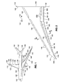
- FIG 7 shown is a plan view of an embodiment of the adaptive trailing edge system 200 mounted to the trailing edge 124.
- the adaptive trailing edge element 202 may be coupled to the trailing edge 124 by one or more element hinge joints 218 defining a hinge axis 220 for the adaptive trailing edge element 202.
- the electric motor actuator 300 is configured as a ball screw actuator 340.
- the ball screw actuator 340 may be coupled to the adaptive trailing edge element 202 by a slider mechanism 380 as is also shown in Figures 5-6 .
- the slider mechanism 380 may include a bellcrank 362 ( Figure 8-9 ) that may be pivotable about a bellcrank pivot axis 364 ( Figure 8-9 ).
- the bellcrank 362 may be pivotably mounted to the trailing edge structure 130 of the trailing edge 124.
- the bellcrank pivot axis 364 may be oriented generally transverse (e.g., generally vertically oriented) to the element hinge axis 220 of the adaptive trailing edge element 202.
- the bellcrank 362 may be coupled to a connector link 388 at a bellcrank-connector joint 390.
- the slider mechanism 380 may include a link connector bar 394 and a slider connector bar 402 for transmitting the actuation force of the electric motor actuator 300 to a plurality of actuation points 384 on the adaptive trailing edge element 202.
- the actuation points 384 may be located at spaced intervals along the adaptive trailing edge element span 214.
- the link connector bar 394 may be supported by one or more support links 386 attached to the trailing edge structure 130.
- the link connector bar 394 may be oriented generally parallel to the adaptive trailing edge element span 214.
- pivoting of the bellcrank 362 may cause the link connector bar 394 to be translated along a lengthwise direction of the link connector bar 394, and along a transverse direction (e.g., perpendicular to the lengthwise direction) of the of the link connector bar 394.
- a plurality of connector links 388 may extend between the link connector bar 394 and the slider connector bar 402.
- the support links 386 may be coupled to the connector links 388 at a plurality of support-connector joints 392 along a length of the link connector bar 394.
- a plurality of slider links 396 ( Figures 8-9 ) may couple the connector links 388 to the adaptive trailing edge element 202 at a plurality of connector-slider joints 400.
- the slider links 396 may be interconnected by the slider connector bar 402 which may be oriented generally parallel to the link connector bar 394.
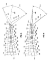
- FIG 8 shown is perspective view of the adaptive trailing edge system 200 incorporating the slider mechanism 380 embodiment of the linkage system 360 as shown in Figure 7 .
- the adaptive trailing edge element 202 may be positioned between a pair of adaptive trailing edge elements 202, each of which may be actuated by a dedicated electric motor actuator 300.
- the slider links 396 may pass through openings 134 formed in the trailing edge spar 132 such as a slot formed in the trailing edge spar 132.
- the openings 134 in the trailing edge spar 132 may be sized and configured complementary to the slider link 396 geometry (e.g. complementary to the cross-sectional size and shape) such that lateral movement of the slider links 396 is prevented during actuation of the adaptive trailing edge element 202.
- the openings 134 in the trailing edge spar 132 may provide a sliding fit with the slider links 396 in such a manner as to prevent lateral movement of the slider links 396 relative to the trailing edge spar 132.
- lateral movement of the slider connector bar 402 and the slider links 396 may be prevented when the slider links 396 slides in and out of the openings 134 in the trailing edge spar 132.
- the slider links 396 may be pivotably coupled to the adaptive trailing edge element 202 by an element link 404 that may be coupled to a forward end of the adaptive trailing edge element 202.
- FIG 9 is a perspective view of the slider mechanism 380 linkage system 360 and the interconnection of the link connector bar 394, the slider connector bar 402, and the slider links 396 during actuation of the adaptive trailing edge element 202.
- Each slider assembly 382 may be comprised of a support link 386, a connector link 388, a slider link 396, and/or an element link 404.
- the adaptive trailing edge element 202 may be actuated by a series of the slider assemblies 382 located at spaced intervals along the adaptive trailing edge element span 214 and defining the plurality of actuation points 384.
- the adaptive trailing edge elements 202 may be configured to resist twisting under aerodynamic loading.
- the mini-plain flap 204 embodiment of the adaptive trailing edge element 202 shown in Figure 5 may have a plurality of ribs sandwiched between upper and lower skin members (not shown) and configured to provide a torsionally rigid structure to resist aeroelastic bending.
- the mini-split flap 206 embodiment of the adaptive trailing edge element 202 shown in Figure 6 may have a skin member configured to be torsionally rigid to resist twisting under aerodynamic loading on unsupported portions of the mini-split flap 206 between the element hinge joints 218 coupling the mini-split flap 206 to the trailing edge 124.
- the adaptive trailing edge elements 202 are not limited to a mini-plain flap 204 embodiment or a mini-split flap 206 embodiment, and may include alternative configurations such as a multi-element split flap, a divergent trailing edge 124, a morphing trailing edge 124, a Gurney flap, and other configurations for the adaptive trailing edge element 202 which may be actuated by the electric motor actuator 300 disclosed herein.
- Figure 10 shows an embodiment of the adaptive trailing edge system 200 wherein the linkage system 360 is configured as a pivot mechanism 370.
- the electric motor actuator 300 is shown configured as a ball screw actuator 340 operatively coupled to the adaptive trailing edge element 202 by the bellcrank 362 and a control rod 372.
- a portion of the control rod 372 may protrude outside of the mold line 116 of the movable trailing edge device 150 (e.g., trailing edge flap 152), or outside of the mold line 116 (not shown) of the fixed trailing edge 126 (not shown) of the wing 114.
- a fairing (not shown) may be required to cover the control rod 372 to minimize aerodynamic drag.
- the bellcrank 362 may be pivotable about the bellcrank pivot axis 364 which may be oriented generally parallel (e.g., generally horizontally oriented) to the hinge axis 220 of the adaptive trailing edge element 202. As indicated above, the bellcrank 362 may be pivotably mounted to the trailing edge structure 130 of the trailing edge 124.
- An element pivot arm 216 may be fixedly coupled to the adaptive trailing edge element 202 and may protrude downwardly from the adaptive trailing edge element 202.
- the control rod 372 may extend between a free end of the element pivot arm 216 and a free end of the bellcrank 362.
- Figure 11 shows a further embodiment of the adaptive trailing edge system 200 wherein the electric motor actuator 300 is provided as a rotary actuator 350 operatively coupled to the adaptive trailing edge element 202 by a pivot mechanism 370.
- the rotary actuator 350 may have one or more mounting tabs 306 for mounting the rotary actuator 350 to the trailing edge structure 130.
- the rotary actuator 350 may include a rotatable output shaft 352 directly coupled to a bellcrank 362.
- the bellcrank 362 may be configured as a pivot arm fixedly coupled to the output shaft 352 of the rotary actuator 350.
- the rotary actuator 350 may be configured to pivot the bellcrank 362 about the bellcrank pivot axis 364 when the rotary actuator 350 is activated.
- the bellcrank pivot axis 364 is oriented normal to the plane of paper.
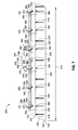
- Figure 12 is a diagrammatic view of an aircraft 100 wing 114 having a plurality of adaptive trailing edge elements 202 mounted on the device trailing edges 128 of the trailing edge devices 150, and an adaptive trailing edge element 202 mounted to the fixed trailing edge 126 of the wing 114 at a location outboard 142 of the ailerons 156.
- the aircraft 100 may include a central controller 500 and a central power supply 502 for providing power and control signals to the electric motor actuators 300.
- control of the plurality of adaptive trailing edge systems 200 may be divided among a plurality of remote electronic units 504 (REU). Each one of the remote electronic units 504 may be communicatively coupled to a subset of the electric motor actuators 300.
- REU remote electronic units
- one of the remote electronic units 504 on each wing 114 may be communicatively coupled to the adaptive trailing edge systems 200 of the inboard 140 flaps 152 and the flaperon 154.
- the remaining remote electronic unit 504 may be communicatively coupled to the adaptive trailing edge systems 200 of the outboard 142 flaps 152, the aileron 156, and the fixed trailing edge 126 portion of the wing 114.
- Power to the remote electronic units 504 may be provided by the central power supply 502 via one or more electric supply lines 506.
- power to the electric motor actuators 300 may be provided by the central power supply 502 via the electric supply lines 506 in the manner illustrated.
- the power switching 510 module may be configured to control the distribution of power to the remote electronic units 504 and to the individual electric motor actuators 300.
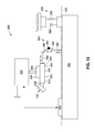
- Figure 13 is a schematic view of an embodiment of an adaptive trailing edge system 200 wherein the electric motor actuator 300 is configured as a ball screw actuator 340.
- the electric motor actuator 300 may be configured as a rotary actuator 350 or other suitable actuation device.
- the ball screw actuator 340 may be coupled to the adaptive trailing edge element 202 by means of the linkage system 360 which may include the bellcrank 362.
- the adaptive trailing edge system 200 may include a motor control unit 302 for controlling the electric motor actuator 300.
- the motor control unit 302 may be powered by the central power supply 502 and may receive command signals from the central controller 500 for controlling the electric motor actuator 300.
- a resolver 330 may be included with the adaptive trailing edge system 200 for monitoring the position of the adaptive trailing edge element 202, and providing signals to the motor control unit 302. The signals may be representative of a desired target position or deflection angle 212 of the adaptive trailing edge element 202.
- the electric motor actuator 300 may include a position sensor 322 configured to sense the electric motor 308 position and/or the position of the output shaft 352 or threaded shaft 344. Position data provided by the position sensor 322 may be used in conjunction with position information from the resolver to assist in determining the position of the adaptive trailing edge element 202.
- the electric motor actuator 300 may include a power-off brake 320 that may receive power from the motor control unit 302 for releasing the power-off brake 320.
- the power-off brake 320 may be coupled to the electric motor 308 and may be configured to prevent rotation of the electric motor 308 when the power-off brake 320 is applied such as during periods when the adaptive trailing edge 124 has been positioned at a desired deflection angle 212.
- the power-off brake 320 may be released to allow rotation of the electric motor 308 so that the adaptive trailing edge element 202 may be retracted or moved to a different deflection angle.
- the adaptive trailing edge system 200 may optionally include a damper 324 mounted to the trailing edge structure 130 and coupled to the adaptive trailing edge element 202.
- the damper 324 may be configured to dampen vibrations or flutter that may be aerodynamically induced in the adaptive trailing edge element 202.
- the damper 324 may include a piston/cylinder 326 arrangement and/or a spring 328 arrangement for damping movement of the adaptive trailing edge element 202.
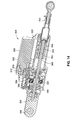
- FIG 14 shows an embodiment of the ball screw actuator 340.
- the ball screw actuator 340 may include a housing 304 having one or more mounting tabs 306 for mounting the ball screw actuator 340 to the trailing edge structure 130.
- the electric motor 308 may be coupled to a linear ball screw drive 342 of the ball screw actuator 340 by means of a motor pinion 312 mounted on a motor shaft 310 of the electric motor 308.
- the motor pinion 312 may engage an inner gear 318 mounted on an inner shaft 316 of a gear system 314 of the ball screw actuator 340.
- the inner gear 318 may be engaged to a mating gear (not shown) of the power-off brake 320.
- the threaded sleeve 346 may be coupled to or integrated with the output shaft 352.
- the output shaft 352 may include an end fitting to which the bellcrank 362 may be coupled.
- the ball screw drive 342 may cause pivoting of the bellcrank 362 and resulting in actuation of the adaptive trailing edge element 202.
- the rotary actuator 350 may be configured similar to the ball screw actuator 340 of Figure 14 , with the difference that for the rotary actuator 350, the threaded shaft 344 and threaded sleeve 346 may be omitted, and the rotatable output shaft 352 of the rotary actuator 350 may be directly coupled to the bellcrank 362 for pivoting the bellcrank 362 about the bellcrank pivot axis 364 as shown in Figure 11 .
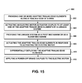
- Step 602 of the method 600 of Figure 15 may include an optional step of providing one or more adaptive trailing edge elements 202 along a trailing edge 124 of an aircraft 100 wing 114.
- one or more (e.g., four) adaptive trailing edge elements 202 may be mounted to the device trailing edge 128 of the inboard 140 flap 152.
- one or more (e.g., five) adaptive trailing edge elements 202 may be mounted to the device trailing edges 128 of the outboard 142 flaps 152.
- one or more adaptive trailing edge elements 202 may be mounted to the device trailing edge 128 of the flaperon 154 located between the inboard 140 flap 152 and the outboard 142 flaps 152. In addition, one or more adaptive trailing edge elements 202 may be mounted to each aileron 156 located outboard 142 of the flaps 152.
- one or more of the adaptive trailing edge elements 202 may be mounted to the fixed trailing edge 126 of the wing 114 such as outboard 142 of the aileron 156.
- the aircraft 100 may be provided in an embodiment where conventional high lift trailing edge devices 150 such as the inboard 140 and outboard 142 trailing edge flaps 152 may be replaced by a series of adaptive trailing edge elements 202 mounted to the fixed trailing edge 126 of the wing 114.
- the adaptive trailing edge elements 202 may be configured as mini-plain flaps 204 and/or mini-split flaps 206 as shown in Figures 5-6 , or in other adaptive trailing edge element 202 configurations such as multi-element split flaps 206, Gurney flaps, or in other configurations.
- step 602 may not be included and the method may begin at step 604.
- Step 604 of the method 600 of Figure 15 may include activating the electric motor actuator 300 which may be operatively coupled to the adaptive trailing edge elements 202, for example by a linkage system 360.
- each adaptive trailing edge element 202 is shown as being coupled to a single, dedicated electric motor actuator 300, the adaptive trailing edge system 200 may be provided in an embodiment wherein two or more adaptive trailing edge elements 202 are coupled to a single electric motor actuator 300.
- the electric motor actuator 300 may be configured as a ball screw actuator 340, a rotary actuator 350, or other mechanical actuation configurations providing inherently high stiffness to reduce or minimize the need to account for compliance in the electric motor actuator 300.
- Step 606 of the method 600 of Figure 15 may include providing the linkage system 360 as a pivot mechanism 370 or as a slider mechanism 380.
- each one of the linkage systems 360 may include a bellcrank 362 having a bellcrank pivot axis 364.
- the bellcrank 362 may pivot about a bellcrank pivot axis 364 ( Figures 10-11 ) that may be oriented generally parallel to the hinge axis 220 of the adaptive trailing edge element 202 such that the bellcrank 362 is rotated within a plane that is generally transverse to the hinge axis 220.
- the bellcrank pivot axis 364 ( Figures 8-9 ) may be oriented generally transverse (e.g., generally vertically oriented) to the hinge axis 220 of the adaptive trailing edge element 202 such that the bellcrank 362 is rotated within a plane that is generally parallel to the hinge axis 220.
- Step 608 of the method 600 of Figure 15 may include actuating the adaptive trailing edge 124 in response to activating the electric motor 308 and pivoting the bellcrank 362 about the bellcrank pivot axis 364.
- the adaptive trailing edge element 202 may be actuated independently of the actuation of the trailing edge device 150 to which the adaptive trailing edge element 202 is mounted.
- the electric motor actuator 300 may include a position sensor 322 and/or a resolver 330 for sensing a position of the adaptive trailing edge element 202 as indicated above.
- Position data may be provided to the motor control unit 302 and/or to the central controller 500 from the position sensor 322 and/or the resolver 330 for use in generating command signals.
- the command signals may be transmitted along one or more command lines 508 for actuating one or more of the adaptive trailing edge elements 202 to a target deflection angle 212.
- Step 610 of the method 600 of Figure 15 may include differentially deploying a plurality of the adaptive trailing edge elements 202.
- the adaptive trailing edge elements 202 may be mounted in series along the trailing edge 124 of a wing 114.
- Differential deployment of the adaptive trailing edge elements 202 may provide a means for varying a wing camber of the wing 114 along a spanwise direction in response to differential deployment of the adaptive trailing edge elements 202. Varying the wing camber may provide a number of aerodynamic performance benefits including, but not limited to, reducing aerodynamic drag, increasing lift, and/or improving spanwise load distribution of the wings 114.
- Step 612 of the method 600 of Figure 15 may include applying the power-off brake 320.
- each one of electric motor actuators 300 may include a power-off brake 320 that may be coupled to the electric motor 308. Power is removed from the power-off brake 320 when the electric motor 308 is non-activated to prevent movement of the adaptive trailing edge element 202.
- the power-off brake 320 may be released by providing relatively low voltage power to the power-off brake 320, and relatively high voltage may be provided to the electric motor 308 such that the adaptive trailing edge element 202 may be actuated.
- One or more of the steps of the method 600 described above may be optional. In some examples, methods according to the present disclosure may be performed with some of the steps described herein omitted without departing from the scope of the present disclosure.
- an adaptive trailing edge system comprising an adaptive trailing edge element mounted to a trailing edge; an electric motor actuator including an electric motor configured to actuate the adaptive trailing edge element; and a linkage system coupling the electric motor actuator to the adaptive trailing edge element for actuation thereof.
- the adaptive trailing edge system disclosed wherein the linkage system comprises a pivot mechanism including a bellcrank pivotable about a bellcrank pivot axis, the bellcrank pivot axis oriented generally parallel to a hinge axis of the adaptive trailing edge element.
- the adaptive trailing edge system disclosed wherein the linkage system comprises a slider mechanism including a bellcrank pivotable about a bellcrank pivot axis, the bellcrank pivot axis oriented generally transverse to a hinge axis of the adaptive trailing edge element.
- the adaptive trailing edge system disclosed wherein the slider mechanism further includes a connector link coupled to the bellcrank at a bellcrank-connector joint; a slider link coupled to the connector link at a connector-slider joint, and the slider link passing through a trailing edge spar and being coupled to the adaptive trailing edge element.
- the adaptive trailing edge system disclosed wherein the electric motor actuator is configured as one of a ball screw actuator and a rotary actuator.
- the ball screw actuator includes a linear ball screw drive coupled to a bellcrank for pivoting the bellcrank about a bellcrank pivot axis.
- the adaptive trailing edge system disclosed wherein the rotary actuator has a rotatable output shaft directly coupled to a bellcrank for pivoting the bellcrank about a bellcrank pivot axis.
- the adaptive trailing edge system disclosed further comprising a power-off brake configured to prevent rotation of the electric motor when the power-off brake is applied.
- the adaptive trailing edge system disclosed wherein the adaptive trailing edge element comprises one of a mini-plain flap and a mini-split flap.
- an aircraft comprising a wing; an adaptive trailing edge element mounted to a trailing edge of the wing; an electric motor actuator including an electric motor configured to actuate the adaptive trailing edge element; and a linkage system coupling the electric motor actuator to the adaptive trailing edge element for actuation thereof.
- a method of actuating an adaptive trailing edge element comprising the steps of activating an electric motor actuator coupled to an adaptive trailing edge element, the adaptive trailing edge element mounted to a trailing edge of an aircraft wing, and the electric motor actuator coupled to the adaptive trailing edge by a linkage system; and actuating the adaptive trailing edge element in response to activating the electric motor.
- the adaptive trailing edge element is one of a plurality of adaptive trailing edge elements disposed along the trailing edge of the aircraft wing, the method further comprising differentially deploying one or more of the plurality of the adaptive trailing edge elements; and varying a wing camber along a spanwise direction of the wing in response to differentially deploying the adaptive trailing edge elements.
- the adaptive trailing edge element comprises one of a mini-plain flap and a mini-split flap.
- the trailing edge comprises at least one of the following: a fixed trailing edge of an aircraft wing, a trailing edge device movably coupled to a wing of an aircraft.
- the linkage system includes a pivot mechanism comprising a bellcrank with a pivot axis oriented generally parallel to a hinge axis of the adaptive trailing edge element, the method further comprising pivoting the bellcrank about the bellcrank pivot axis; and actuating the adaptive trailing edge element in response to pivoting the bellcrank about a bellcrank pivot axis.
- the linkage system includes a slider mechanism comprising a bellcrank with a pivot axis oriented generally transverse to a hinge axis of the adaptive trailing edge element, the method wherein pivoting the bellcrank about a bellcrank pivot axis; and actuating the adaptive trailing edge element in response to pivoting the bellcrank about the bellcrank pivot axis.
- the method disclosed further comprising actuating the adaptive trailing edge element independent of an actuation of a trailing edge device pivotably mounted to the wing.
- the method disclosed further comprising preventing rotation of the electric motor by applying a power-off brake coupled to the electric motor.
Landscapes
- Engineering & Computer Science (AREA)
- Aviation & Aerospace Engineering (AREA)
- Automation & Control Theory (AREA)
- Mechanical Engineering (AREA)
- Transmission Devices (AREA)
Applications Claiming Priority (1)
| Application Number | Priority Date | Filing Date | Title |
|---|---|---|---|
| US14/034,946 US10017243B2 (en) | 2013-09-24 | 2013-09-24 | Adaptive trailing edge actuator system and method |
Publications (2)
| Publication Number | Publication Date |
|---|---|
| EP2851287A1 true EP2851287A1 (de) | 2015-03-25 |
| EP2851287B1 EP2851287B1 (de) | 2018-11-07 |
Family
ID=51609976
Family Applications (1)
| Application Number | Title | Priority Date | Filing Date |
|---|---|---|---|
| EP14185991.8A Active EP2851287B1 (de) | 2013-09-24 | 2014-09-23 | Hinterkantenaktuatorsystem und -verfahren |
Country Status (4)
| Country | Link |
|---|---|
| US (1) | US10017243B2 (de) |
| EP (1) | EP2851287B1 (de) |
| CA (1) | CA2857892C (de) |
| ES (1) | ES2709802T3 (de) |
Cited By (5)
| Publication number | Priority date | Publication date | Assignee | Title |
|---|---|---|---|---|
| CN107719644A (zh) * | 2017-10-18 | 2018-02-23 | 中国商用飞机有限责任公司 | 一种襟翼收放装置 |
| CN111924086A (zh) * | 2020-07-07 | 2020-11-13 | 北京机电工程研究所 | 一种记忆合金驱动的可变形机构 |
| WO2022019854A1 (en) * | 2020-07-23 | 2022-01-27 | Tusas- Turk Havacilik Ve Uzay Sanayii Anonim Sirketi | A control surface system |
| EP4253228A1 (de) * | 2022-03-31 | 2023-10-04 | Airbus Operations GmbH | Flügel für ein flugzeug |
| EP4342788A1 (de) * | 2022-09-23 | 2024-03-27 | Airbus Operations GmbH | Flügel für ein flugzeug |
Families Citing this family (15)
| Publication number | Priority date | Publication date | Assignee | Title |
|---|---|---|---|---|
| CN108698684A (zh) * | 2016-02-29 | 2018-10-23 | 弗莱克斯塞思股份有限公司 | 用于翼面的边缘变形装置 |
| US10443696B1 (en) * | 2016-08-03 | 2019-10-15 | Rockwell Collins, Inc. | No-back brake creep inhibitor |
| CN106597847B (zh) * | 2016-11-09 | 2020-03-17 | 南京航空航天大学 | 一种基于递归神经网络的机动载荷控制器及其控制方法 |
| US11052989B2 (en) * | 2017-09-12 | 2021-07-06 | Aurora Flight Sciences Corporation | Active wing-twist mechanism and control system |
| US10974816B2 (en) * | 2017-09-28 | 2021-04-13 | The Boeing Company | High-fowler flap actuation apparatus and related methods |
| US11059569B1 (en) * | 2017-12-29 | 2021-07-13 | United States Of America As Represented By The Administrator Of Nasa | Flight control system for aircraft having multi-functional flight control surface |
| JP7096698B2 (ja) * | 2018-04-23 | 2022-07-06 | 株式会社Subaru | 翼構造体、翼構造体の制御方法及び航空機 |
| CN110758717B (zh) * | 2019-12-06 | 2022-03-18 | 湖南浩天翼航空技术有限公司 | 一种内藏式机翼舵面驱动机构 |
| CN112238933A (zh) * | 2020-10-15 | 2021-01-19 | 中国商用飞机有限责任公司 | 一种用于引导飞机后缘襟翼运动的滑动装置 |
| CN112733253B (zh) * | 2020-12-28 | 2022-09-20 | 北京航空航天大学 | 一种波纹板形式柔性后缘机翼结构的设计方法 |
| EP4234395A1 (de) | 2022-02-25 | 2023-08-30 | Airbus Operations GmbH | Vorrichtung zur entlastung der flügelspitze eines flugzeuges, verfahren zur entlastung der flügelspitze eines flugzeuges und flugzeug |
| GB2620625A (en) * | 2022-07-14 | 2024-01-17 | Airbus Operations Ltd | Aircraft wing trailing edge device |
| EP4331975A1 (de) | 2022-09-01 | 2024-03-06 | Airbus Operations GmbH | Hinterkantensystem für einen flugzeugflügel, verfahren zum antrieb von steuerflächen eines flugzeugs, flugzeugflügel und flugzeug |
| CN115158635B (zh) * | 2022-09-08 | 2022-12-23 | 之江实验室 | 一种自适应变形和自主抑振的智能机翼模块及控制方法 |
| CN116280177A (zh) * | 2023-05-08 | 2023-06-23 | 中国空气动力研究与发展中心低速空气动力研究所 | 一种带后缘小翼的翼型动态失速主动控制装置 |
Citations (7)
| Publication number | Priority date | Publication date | Assignee | Title |
|---|---|---|---|---|
| US2524605A (en) * | 1944-11-23 | 1950-10-03 | Sncaso | Arrangement for securing and controlling a movable flap at the trailing edge of an airplane wing |
| US5651513A (en) * | 1995-03-01 | 1997-07-29 | Northrop Grumman Corporation | Linear flap drive system |
| US5884872A (en) * | 1993-05-26 | 1999-03-23 | The United States Of America As Represented By The Secretary Of The Navy | Oscillating flap lift enhancement device |
| EP0909705A2 (de) * | 1997-10-16 | 1999-04-21 | Northrop Grumman Corporation | Scherengestänge für einen Spaltklappenverstellmechanismus |
| FR2770826A1 (fr) * | 1997-11-07 | 1999-05-14 | Eurocopter France | Pale de rotor a volet orientable |
| US20030057332A1 (en) * | 2001-09-27 | 2003-03-27 | Detlev Schwetzler | Flap arrangement for varying the aerodynamic lift generated by an aerodynamic element of an aircraft |
| EP1780121A1 (de) * | 2005-10-26 | 2007-05-02 | Eurocopter | Rotorblatt versehen mit einer schwenbaren Klappe und mit einer Befestigungslasche |
Family Cites Families (32)
| Publication number | Priority date | Publication date | Assignee | Title |
|---|---|---|---|---|
| US2137879A (en) * | 1935-02-26 | 1938-11-22 | Ksoll Joseph | Supporting surface for flying machines |
| US2146014A (en) * | 1936-05-06 | 1939-02-07 | Charles H Grant | Variable camber wing |
| US2254304A (en) * | 1938-07-27 | 1941-09-02 | Zap Dev Corp | Aileron and flap |
| GB1339662A (en) * | 1971-03-12 | 1973-12-05 | British Aircraft Corp Ltd | Aircraft |
| US3822047A (en) * | 1972-12-14 | 1974-07-02 | Collins Radio Co | Takeoff and go-around climb-out profile pitch command formulation for aircraft |
| US4049219A (en) * | 1975-02-03 | 1977-09-20 | The Boeing Company | Variable pivot trailing edge flap |
| US4702442A (en) * | 1984-12-06 | 1987-10-27 | The Boeing Company | Aircraft trailing edge flap apparatus |
| US4582278A (en) * | 1985-02-15 | 1986-04-15 | Northrop Corporation | Air foil having adjustable shape |
| DE3527497A1 (de) * | 1985-07-31 | 1987-02-12 | Airbus Gmbh | Tragfluegel mit ausfahrbarer klappe und veraenderbarer woelbung |
| DE3624675A1 (de) * | 1986-07-22 | 1988-02-04 | Dornier Gmbh | Einrichtung zur verstellung von klappen, insbesondere hochauftriebsklappen an flugzeugtragfluegeln |
| GB8711252D0 (en) * | 1987-05-13 | 1987-07-15 | British Aerospace | High lift device |
| US5098043A (en) * | 1990-02-27 | 1992-03-24 | Grumman Aerospace Corporation | Integrated power hinge actuator |
| US5544847A (en) * | 1993-11-10 | 1996-08-13 | The Boeing Company | Leading edge slat/wing combination |
| SE9601956D0 (sv) * | 1996-05-22 | 1996-05-22 | Saab Ab | Segmenterad klaff med variabel krökning för flygplansvinge |
| DE19643222C2 (de) * | 1996-10-19 | 1998-12-10 | Daimler Benz Ag | Auftriebskörper mit veränderbarer Wölbung |
| FR2778164B1 (fr) | 1998-04-29 | 2000-06-23 | Aerospatiale | Systeme de commande mixte pour surface aerodynamique d'aeronef |
| US6481667B1 (en) * | 2001-03-05 | 2002-11-19 | Northrop Grumman Corporation | System and method for deflecting an aerodynamic control surface |
| US6467733B1 (en) * | 2001-11-28 | 2002-10-22 | Northrop Grumman Corporation | Aerodynamic control surface system |
| DE10313728B4 (de) * | 2003-03-27 | 2011-07-21 | Airbus Operations GmbH, 21129 | Klappensystem am Tragflügel eines Starrflügel-Flugzeuges |
| US7494094B2 (en) * | 2004-09-08 | 2009-02-24 | The Boeing Company | Aircraft wing systems for providing differential motion to deployable lift devices |
| DE102004049504A1 (de) * | 2004-10-11 | 2006-04-13 | Airbus Deutschland Gmbh | Flugzeugflügel, Verfahren zum Betreiben eines Flugzeugflügels und Verwendung einer schwenkbaren Hinterkante an einem Hauptflügel eines Flugzeugflügels zum Justieren der Form und Breite eines Luftspalts |
| US7367532B2 (en) * | 2005-01-31 | 2008-05-06 | John Libby | High lift longitudinal axis control system |
| US7641152B2 (en) * | 2007-04-13 | 2010-01-05 | The Boeing Company | Dynamic adjustment of wing surfaces for variable camber |
| DE102007027137B4 (de) | 2007-06-06 | 2020-06-25 | Liebherr-Aerospace Lindenberg Gmbh | Bremseinheit eines Antriebssystems für Landeklappen und/oder Vorflügel zum Festlegen eines Antriebselementes |
| DE102007055669A1 (de) * | 2007-11-21 | 2009-06-04 | Airbus Deutschland Gmbh | Landeklappenkinematik angetrieben über Ritzelantrieb |
| US7992825B2 (en) * | 2008-07-23 | 2011-08-09 | Airbus Espana, S.L. | Control surface of aircraft |
| GB0920968D0 (en) * | 2009-11-27 | 2010-01-13 | Airbus Operations Ltd | Trailing edge flap |
| GB0920969D0 (en) * | 2009-11-27 | 2010-01-13 | Airbus Operations Ltd | Trailing edge flap |
| GB0921007D0 (en) * | 2009-11-30 | 2010-01-13 | Airbus Operations Ltd | Trailing edge flap |
| US8424810B1 (en) * | 2010-03-31 | 2013-04-23 | The Boeing Company | Low noise wing slat system with rigid cove-filled slat |
| DE102010021576A1 (de) * | 2010-05-26 | 2011-12-01 | Airbus Operations Gmbh | Vorrichtung für eine Stellklappe eines Tragflügels |
| US8356766B2 (en) * | 2010-09-14 | 2013-01-22 | The United States Of America As Represented By The Secretary Of The Navy | Winder for rectangular cross-section wire |
-
2013
- 2013-09-24 US US14/034,946 patent/US10017243B2/en active Active
-
2014
- 2014-07-28 CA CA2857892A patent/CA2857892C/en active Active
- 2014-09-23 EP EP14185991.8A patent/EP2851287B1/de active Active
- 2014-09-23 ES ES14185991T patent/ES2709802T3/es active Active
Patent Citations (7)
| Publication number | Priority date | Publication date | Assignee | Title |
|---|---|---|---|---|
| US2524605A (en) * | 1944-11-23 | 1950-10-03 | Sncaso | Arrangement for securing and controlling a movable flap at the trailing edge of an airplane wing |
| US5884872A (en) * | 1993-05-26 | 1999-03-23 | The United States Of America As Represented By The Secretary Of The Navy | Oscillating flap lift enhancement device |
| US5651513A (en) * | 1995-03-01 | 1997-07-29 | Northrop Grumman Corporation | Linear flap drive system |
| EP0909705A2 (de) * | 1997-10-16 | 1999-04-21 | Northrop Grumman Corporation | Scherengestänge für einen Spaltklappenverstellmechanismus |
| FR2770826A1 (fr) * | 1997-11-07 | 1999-05-14 | Eurocopter France | Pale de rotor a volet orientable |
| US20030057332A1 (en) * | 2001-09-27 | 2003-03-27 | Detlev Schwetzler | Flap arrangement for varying the aerodynamic lift generated by an aerodynamic element of an aircraft |
| EP1780121A1 (de) * | 2005-10-26 | 2007-05-02 | Eurocopter | Rotorblatt versehen mit einer schwenbaren Klappe und mit einer Befestigungslasche |
Cited By (7)
| Publication number | Priority date | Publication date | Assignee | Title |
|---|---|---|---|---|
| CN107719644A (zh) * | 2017-10-18 | 2018-02-23 | 中国商用飞机有限责任公司 | 一种襟翼收放装置 |
| WO2019076341A1 (zh) * | 2017-10-18 | 2019-04-25 | 中国商用飞机有限责任公司 | 一种襟翼收放装置 |
| CN107719644B (zh) * | 2017-10-18 | 2021-09-10 | 中国商用飞机有限责任公司 | 一种襟翼收放装置 |
| CN111924086A (zh) * | 2020-07-07 | 2020-11-13 | 北京机电工程研究所 | 一种记忆合金驱动的可变形机构 |
| WO2022019854A1 (en) * | 2020-07-23 | 2022-01-27 | Tusas- Turk Havacilik Ve Uzay Sanayii Anonim Sirketi | A control surface system |
| EP4253228A1 (de) * | 2022-03-31 | 2023-10-04 | Airbus Operations GmbH | Flügel für ein flugzeug |
| EP4342788A1 (de) * | 2022-09-23 | 2024-03-27 | Airbus Operations GmbH | Flügel für ein flugzeug |
Also Published As
| Publication number | Publication date |
|---|---|
| EP2851287B1 (de) | 2018-11-07 |
| US20150083853A1 (en) | 2015-03-26 |
| ES2709802T3 (es) | 2019-04-17 |
| CA2857892C (en) | 2018-04-17 |
| CA2857892A1 (en) | 2015-03-24 |
| US10017243B2 (en) | 2018-07-10 |
Similar Documents
| Publication | Publication Date | Title |
|---|---|---|
| EP2851287B1 (de) | Hinterkantenaktuatorsystem und -verfahren | |
| US11440645B2 (en) | Adjustable lift modification wingtip | |
| EP2851284B1 (de) | Variables Wölbklappensystem und Verfahren | |
| US8342447B2 (en) | Morphing control surface transition | |
| US9856012B2 (en) | Morphing wing for an aircraft | |
| EP2669190B2 (de) | Drehbar betätigtes Hochauftriebspaltquerruder | |
| US10654557B2 (en) | Morphing skin for an aircraft | |
| EP3699081B1 (de) | Flugzeugflügel mit verschiebbarem winglet | |
| RU2405715C2 (ru) | Поверхность управления задней кромкой крыла самолета | |
| CA2710119C (en) | Aircraft control surface | |
| US8622350B1 (en) | Compound leading edge device for aircraft | |
| US11505304B2 (en) | Aircraft spoiler actuation systems and related methods | |
| US9079655B2 (en) | System for increasing controllability for an aircraft | |
| CA2788274C (en) | Active gurney flap | |
| US11685516B2 (en) | Passive gust-load-alleviation device | |
| EP3560821B1 (de) | Steuerflächenbetätigungsmechanismus |
Legal Events
| Date | Code | Title | Description |
|---|---|---|---|
| PUAI | Public reference made under article 153(3) epc to a published international application that has entered the european phase |
Free format text: ORIGINAL CODE: 0009012 |
|
| 17P | Request for examination filed |
Effective date: 20140923 |
|
| AK | Designated contracting states |
Kind code of ref document: A1 Designated state(s): AL AT BE BG CH CY CZ DE DK EE ES FI FR GB GR HR HU IE IS IT LI LT LU LV MC MK MT NL NO PL PT RO RS SE SI SK SM TR |
|
| AX | Request for extension of the european patent |
Extension state: BA ME |
|
| 17Q | First examination report despatched |
Effective date: 20160607 |
|
| STAA | Information on the status of an ep patent application or granted ep patent |
Free format text: STATUS: EXAMINATION IS IN PROGRESS |
|
| REG | Reference to a national code |
Ref country code: DE Ref legal event code: R079 Ref document number: 602014035487 Country of ref document: DE Free format text: PREVIOUS MAIN CLASS: B64C0009160000 Ipc: B64C0003140000 |
|
| GRAP | Despatch of communication of intention to grant a patent |
Free format text: ORIGINAL CODE: EPIDOSNIGR1 |
|
| STAA | Information on the status of an ep patent application or granted ep patent |
Free format text: STATUS: GRANT OF PATENT IS INTENDED |
|
| RIC1 | Information provided on ipc code assigned before grant |
Ipc: B64C 13/28 20060101ALI20171108BHEP Ipc: B64C 13/50 20060101ALI20171108BHEP Ipc: B64C 3/14 20060101AFI20171108BHEP Ipc: B64C 9/16 20060101ALI20171108BHEP |
|
| INTG | Intention to grant announced |
Effective date: 20171212 |
|
| GRAJ | Information related to disapproval of communication of intention to grant by the applicant or resumption of examination proceedings by the epo deleted |
Free format text: ORIGINAL CODE: EPIDOSDIGR1 |
|
| STAA | Information on the status of an ep patent application or granted ep patent |
Free format text: STATUS: EXAMINATION IS IN PROGRESS |
|
| INTC | Intention to grant announced (deleted) | ||
| GRAP | Despatch of communication of intention to grant a patent |
Free format text: ORIGINAL CODE: EPIDOSNIGR1 |
|
| STAA | Information on the status of an ep patent application or granted ep patent |
Free format text: STATUS: GRANT OF PATENT IS INTENDED |
|
| INTG | Intention to grant announced |
Effective date: 20180522 |
|
| GRAS | Grant fee paid |
Free format text: ORIGINAL CODE: EPIDOSNIGR3 |
|
| GRAA | (expected) grant |
Free format text: ORIGINAL CODE: 0009210 |
|
| STAA | Information on the status of an ep patent application or granted ep patent |
Free format text: STATUS: THE PATENT HAS BEEN GRANTED |
|
| AK | Designated contracting states |
Kind code of ref document: B1 Designated state(s): AL AT BE BG CH CY CZ DE DK EE ES FI FR GB GR HR HU IE IS IT LI LT LU LV MC MK MT NL NO PL PT RO RS SE SI SK SM TR |
|
| REG | Reference to a national code |
Ref country code: GB Ref legal event code: FG4D |
|
| REG | Reference to a national code |
Ref country code: CH Ref legal event code: EP Ref country code: AT Ref legal event code: REF Ref document number: 1061743 Country of ref document: AT Kind code of ref document: T Effective date: 20181115 |
|
| REG | Reference to a national code |
Ref country code: IE Ref legal event code: FG4D |
|
| REG | Reference to a national code |
Ref country code: DE Ref legal event code: R096 Ref document number: 602014035487 Country of ref document: DE |
|
| REG | Reference to a national code |
Ref country code: NL Ref legal event code: MP Effective date: 20181107 |
|
| REG | Reference to a national code |
Ref country code: LT Ref legal event code: MG4D |
|
| REG | Reference to a national code |
Ref country code: AT Ref legal event code: MK05 Ref document number: 1061743 Country of ref document: AT Kind code of ref document: T Effective date: 20181107 |
|
| REG | Reference to a national code |
Ref country code: ES Ref legal event code: FG2A Ref document number: 2709802 Country of ref document: ES Kind code of ref document: T3 Effective date: 20190417 |
|
| PG25 | Lapsed in a contracting state [announced via postgrant information from national office to epo] |
Ref country code: LV Free format text: LAPSE BECAUSE OF FAILURE TO SUBMIT A TRANSLATION OF THE DESCRIPTION OR TO PAY THE FEE WITHIN THE PRESCRIBED TIME-LIMIT Effective date: 20181107 Ref country code: AT Free format text: LAPSE BECAUSE OF FAILURE TO SUBMIT A TRANSLATION OF THE DESCRIPTION OR TO PAY THE FEE WITHIN THE PRESCRIBED TIME-LIMIT Effective date: 20181107 Ref country code: IS Free format text: LAPSE BECAUSE OF FAILURE TO SUBMIT A TRANSLATION OF THE DESCRIPTION OR TO PAY THE FEE WITHIN THE PRESCRIBED TIME-LIMIT Effective date: 20190307 Ref country code: FI Free format text: LAPSE BECAUSE OF FAILURE TO SUBMIT A TRANSLATION OF THE DESCRIPTION OR TO PAY THE FEE WITHIN THE PRESCRIBED TIME-LIMIT Effective date: 20181107 Ref country code: NO Free format text: LAPSE BECAUSE OF FAILURE TO SUBMIT A TRANSLATION OF THE DESCRIPTION OR TO PAY THE FEE WITHIN THE PRESCRIBED TIME-LIMIT Effective date: 20190207 Ref country code: LT Free format text: LAPSE BECAUSE OF FAILURE TO SUBMIT A TRANSLATION OF THE DESCRIPTION OR TO PAY THE FEE WITHIN THE PRESCRIBED TIME-LIMIT Effective date: 20181107 Ref country code: HR Free format text: LAPSE BECAUSE OF FAILURE TO SUBMIT A TRANSLATION OF THE DESCRIPTION OR TO PAY THE FEE WITHIN THE PRESCRIBED TIME-LIMIT Effective date: 20181107 Ref country code: BG Free format text: LAPSE BECAUSE OF FAILURE TO SUBMIT A TRANSLATION OF THE DESCRIPTION OR TO PAY THE FEE WITHIN THE PRESCRIBED TIME-LIMIT Effective date: 20190207 |
|
| PG25 | Lapsed in a contracting state [announced via postgrant information from national office to epo] |
Ref country code: RS Free format text: LAPSE BECAUSE OF FAILURE TO SUBMIT A TRANSLATION OF THE DESCRIPTION OR TO PAY THE FEE WITHIN THE PRESCRIBED TIME-LIMIT Effective date: 20181107 Ref country code: SE Free format text: LAPSE BECAUSE OF FAILURE TO SUBMIT A TRANSLATION OF THE DESCRIPTION OR TO PAY THE FEE WITHIN THE PRESCRIBED TIME-LIMIT Effective date: 20181107 Ref country code: NL Free format text: LAPSE BECAUSE OF FAILURE TO SUBMIT A TRANSLATION OF THE DESCRIPTION OR TO PAY THE FEE WITHIN THE PRESCRIBED TIME-LIMIT Effective date: 20181107 Ref country code: GR Free format text: LAPSE BECAUSE OF FAILURE TO SUBMIT A TRANSLATION OF THE DESCRIPTION OR TO PAY THE FEE WITHIN THE PRESCRIBED TIME-LIMIT Effective date: 20190208 Ref country code: AL Free format text: LAPSE BECAUSE OF FAILURE TO SUBMIT A TRANSLATION OF THE DESCRIPTION OR TO PAY THE FEE WITHIN THE PRESCRIBED TIME-LIMIT Effective date: 20181107 Ref country code: PT Free format text: LAPSE BECAUSE OF FAILURE TO SUBMIT A TRANSLATION OF THE DESCRIPTION OR TO PAY THE FEE WITHIN THE PRESCRIBED TIME-LIMIT Effective date: 20190307 |
|
| PG25 | Lapsed in a contracting state [announced via postgrant information from national office to epo] |
Ref country code: PL Free format text: LAPSE BECAUSE OF FAILURE TO SUBMIT A TRANSLATION OF THE DESCRIPTION OR TO PAY THE FEE WITHIN THE PRESCRIBED TIME-LIMIT Effective date: 20181107 Ref country code: CZ Free format text: LAPSE BECAUSE OF FAILURE TO SUBMIT A TRANSLATION OF THE DESCRIPTION OR TO PAY THE FEE WITHIN THE PRESCRIBED TIME-LIMIT Effective date: 20181107 Ref country code: DK Free format text: LAPSE BECAUSE OF FAILURE TO SUBMIT A TRANSLATION OF THE DESCRIPTION OR TO PAY THE FEE WITHIN THE PRESCRIBED TIME-LIMIT Effective date: 20181107 |
|
| REG | Reference to a national code |
Ref country code: DE Ref legal event code: R097 Ref document number: 602014035487 Country of ref document: DE |
|
| PG25 | Lapsed in a contracting state [announced via postgrant information from national office to epo] |
Ref country code: SK Free format text: LAPSE BECAUSE OF FAILURE TO SUBMIT A TRANSLATION OF THE DESCRIPTION OR TO PAY THE FEE WITHIN THE PRESCRIBED TIME-LIMIT Effective date: 20181107 Ref country code: RO Free format text: LAPSE BECAUSE OF FAILURE TO SUBMIT A TRANSLATION OF THE DESCRIPTION OR TO PAY THE FEE WITHIN THE PRESCRIBED TIME-LIMIT Effective date: 20181107 Ref country code: SM Free format text: LAPSE BECAUSE OF FAILURE TO SUBMIT A TRANSLATION OF THE DESCRIPTION OR TO PAY THE FEE WITHIN THE PRESCRIBED TIME-LIMIT Effective date: 20181107 Ref country code: EE Free format text: LAPSE BECAUSE OF FAILURE TO SUBMIT A TRANSLATION OF THE DESCRIPTION OR TO PAY THE FEE WITHIN THE PRESCRIBED TIME-LIMIT Effective date: 20181107 |
|
| PLBE | No opposition filed within time limit |
Free format text: ORIGINAL CODE: 0009261 |
|
| STAA | Information on the status of an ep patent application or granted ep patent |
Free format text: STATUS: NO OPPOSITION FILED WITHIN TIME LIMIT |
|
| 26N | No opposition filed |
Effective date: 20190808 |
|
| PG25 | Lapsed in a contracting state [announced via postgrant information from national office to epo] |
Ref country code: SI Free format text: LAPSE BECAUSE OF FAILURE TO SUBMIT A TRANSLATION OF THE DESCRIPTION OR TO PAY THE FEE WITHIN THE PRESCRIBED TIME-LIMIT Effective date: 20181107 |
|
| REG | Reference to a national code |
Ref country code: DE Ref legal event code: R082 Ref document number: 602014035487 Country of ref document: DE Representative=s name: MAIER, LL.M., MICHAEL C., DE Ref country code: DE Ref legal event code: R082 Ref document number: 602014035487 Country of ref document: DE Representative=s name: BOULT WADE TENNANT LLP, DE |
|
| REG | Reference to a national code |
Ref country code: DE Ref legal event code: R082 Ref document number: 602014035487 Country of ref document: DE Representative=s name: BOULT WADE TENNANT LLP, DE |
|
| PG25 | Lapsed in a contracting state [announced via postgrant information from national office to epo] |
Ref country code: TR Free format text: LAPSE BECAUSE OF FAILURE TO SUBMIT A TRANSLATION OF THE DESCRIPTION OR TO PAY THE FEE WITHIN THE PRESCRIBED TIME-LIMIT Effective date: 20181107 |
|
| PG25 | Lapsed in a contracting state [announced via postgrant information from national office to epo] |
Ref country code: MC Free format text: LAPSE BECAUSE OF FAILURE TO SUBMIT A TRANSLATION OF THE DESCRIPTION OR TO PAY THE FEE WITHIN THE PRESCRIBED TIME-LIMIT Effective date: 20181107 |
|
| REG | Reference to a national code |
Ref country code: CH Ref legal event code: PL |
|
| PG25 | Lapsed in a contracting state [announced via postgrant information from national office to epo] |
Ref country code: CH Free format text: LAPSE BECAUSE OF NON-PAYMENT OF DUE FEES Effective date: 20190930 Ref country code: IE Free format text: LAPSE BECAUSE OF NON-PAYMENT OF DUE FEES Effective date: 20190923 Ref country code: LU Free format text: LAPSE BECAUSE OF NON-PAYMENT OF DUE FEES Effective date: 20190923 Ref country code: LI Free format text: LAPSE BECAUSE OF NON-PAYMENT OF DUE FEES Effective date: 20190930 |
|
| REG | Reference to a national code |
Ref country code: BE Ref legal event code: MM Effective date: 20190930 |
|
| PG25 | Lapsed in a contracting state [announced via postgrant information from national office to epo] |
Ref country code: BE Free format text: LAPSE BECAUSE OF NON-PAYMENT OF DUE FEES Effective date: 20190930 |
|
| PG25 | Lapsed in a contracting state [announced via postgrant information from national office to epo] |
Ref country code: CY Free format text: LAPSE BECAUSE OF FAILURE TO SUBMIT A TRANSLATION OF THE DESCRIPTION OR TO PAY THE FEE WITHIN THE PRESCRIBED TIME-LIMIT Effective date: 20181107 |
|
| PG25 | Lapsed in a contracting state [announced via postgrant information from national office to epo] |
Ref country code: HU Free format text: LAPSE BECAUSE OF FAILURE TO SUBMIT A TRANSLATION OF THE DESCRIPTION OR TO PAY THE FEE WITHIN THE PRESCRIBED TIME-LIMIT; INVALID AB INITIO Effective date: 20140923 Ref country code: MT Free format text: LAPSE BECAUSE OF FAILURE TO SUBMIT A TRANSLATION OF THE DESCRIPTION OR TO PAY THE FEE WITHIN THE PRESCRIBED TIME-LIMIT Effective date: 20181107 |
|
| PG25 | Lapsed in a contracting state [announced via postgrant information from national office to epo] |
Ref country code: MK Free format text: LAPSE BECAUSE OF FAILURE TO SUBMIT A TRANSLATION OF THE DESCRIPTION OR TO PAY THE FEE WITHIN THE PRESCRIBED TIME-LIMIT Effective date: 20181107 |
|
| P01 | Opt-out of the competence of the unified patent court (upc) registered |
Effective date: 20230516 |
|
| PGFP | Annual fee paid to national office [announced via postgrant information from national office to epo] |
Ref country code: IT Payment date: 20230921 Year of fee payment: 10 Ref country code: GB Payment date: 20230927 Year of fee payment: 10 |
|
| PGFP | Annual fee paid to national office [announced via postgrant information from national office to epo] |
Ref country code: FR Payment date: 20230925 Year of fee payment: 10 Ref country code: DE Payment date: 20230927 Year of fee payment: 10 |
|
| PGFP | Annual fee paid to national office [announced via postgrant information from national office to epo] |
Ref country code: ES Payment date: 20231002 Year of fee payment: 10 |