EP2851280A1 - Modular azimuth thruster - Google Patents
Modular azimuth thruster Download PDFInfo
- Publication number
- EP2851280A1 EP2851280A1 EP13185723.7A EP13185723A EP2851280A1 EP 2851280 A1 EP2851280 A1 EP 2851280A1 EP 13185723 A EP13185723 A EP 13185723A EP 2851280 A1 EP2851280 A1 EP 2851280A1
- Authority
- EP
- European Patent Office
- Prior art keywords
- thruster
- core unit
- housing
- azimuth
- azimuth thruster
- Prior art date
- Legal status (The legal status is an assumption and is not a legal conclusion. Google has not performed a legal analysis and makes no representation as to the accuracy of the status listed.)
- Granted
Links
- 230000005540 biological transmission Effects 0.000 claims abstract description 11
- 238000000034 method Methods 0.000 claims abstract description 11
- XLYOFNOQVPJJNP-UHFFFAOYSA-N water Substances O XLYOFNOQVPJJNP-UHFFFAOYSA-N 0.000 claims abstract description 8
- 239000002131 composite material Substances 0.000 claims description 5
- ZZUFCTLCJUWOSV-UHFFFAOYSA-N furosemide Chemical compound C1=C(Cl)C(S(=O)(=O)N)=CC(C(O)=O)=C1NCC1=CC=CO1 ZZUFCTLCJUWOSV-UHFFFAOYSA-N 0.000 claims description 4
- 239000007769 metal material Substances 0.000 claims description 4
- OKTJSMMVPCPJKN-UHFFFAOYSA-N Carbon Chemical compound [C] OKTJSMMVPCPJKN-UHFFFAOYSA-N 0.000 claims description 2
- 229920002430 Fibre-reinforced plastic Polymers 0.000 claims description 2
- 229910052799 carbon Inorganic materials 0.000 claims description 2
- 239000011151 fibre-reinforced plastic Substances 0.000 claims description 2
- 229920000642 polymer Polymers 0.000 claims description 2
- 229920002635 polyurethane Polymers 0.000 claims description 2
- 239000004814 polyurethane Substances 0.000 claims description 2
- 238000004519 manufacturing process Methods 0.000 description 12
- 230000000694 effects Effects 0.000 description 5
- 238000011144 upstream manufacturing Methods 0.000 description 5
- 230000008901 benefit Effects 0.000 description 4
- 229910001018 Cast iron Inorganic materials 0.000 description 3
- 239000000463 material Substances 0.000 description 3
- 229910001208 Crucible steel Inorganic materials 0.000 description 2
- 230000008859 change Effects 0.000 description 2
- 230000008569 process Effects 0.000 description 2
- 230000009467 reduction Effects 0.000 description 2
- 239000010959 steel Substances 0.000 description 2
- 230000009471 action Effects 0.000 description 1
- 230000009286 beneficial effect Effects 0.000 description 1
- 239000007795 chemical reaction product Substances 0.000 description 1
- 238000002485 combustion reaction Methods 0.000 description 1
- 238000002955 isolation Methods 0.000 description 1
- 239000000203 mixture Substances 0.000 description 1
- 239000000047 product Substances 0.000 description 1
- 230000008439 repair process Effects 0.000 description 1
- 238000007493 shaping process Methods 0.000 description 1
- 239000000725 suspension Substances 0.000 description 1
- 230000036967 uncompetitive effect Effects 0.000 description 1
Images


Classifications
-
- B—PERFORMING OPERATIONS; TRANSPORTING
- B63—SHIPS OR OTHER WATERBORNE VESSELS; RELATED EQUIPMENT
- B63H—MARINE PROPULSION OR STEERING
- B63H5/00—Arrangements on vessels of propulsion elements directly acting on water
- B63H5/07—Arrangements on vessels of propulsion elements directly acting on water of propellers
- B63H5/125—Arrangements on vessels of propulsion elements directly acting on water of propellers movably mounted with respect to hull, e.g. adjustable in direction, e.g. podded azimuthing thrusters
-
- B—PERFORMING OPERATIONS; TRANSPORTING
- B63—SHIPS OR OTHER WATERBORNE VESSELS; RELATED EQUIPMENT
- B63H—MARINE PROPULSION OR STEERING
- B63H25/00—Steering; Slowing-down otherwise than by use of propulsive elements; Dynamic anchoring, i.e. positioning vessels by means of main or auxiliary propulsive elements
- B63H25/42—Steering or dynamic anchoring by propulsive elements; Steering or dynamic anchoring by propellers used therefor only; Steering or dynamic anchoring by rudders carrying propellers
-
- B—PERFORMING OPERATIONS; TRANSPORTING
- B63—SHIPS OR OTHER WATERBORNE VESSELS; RELATED EQUIPMENT
- B63H—MARINE PROPULSION OR STEERING
- B63H5/00—Arrangements on vessels of propulsion elements directly acting on water
- B63H5/07—Arrangements on vessels of propulsion elements directly acting on water of propellers
- B63H5/125—Arrangements on vessels of propulsion elements directly acting on water of propellers movably mounted with respect to hull, e.g. adjustable in direction, e.g. podded azimuthing thrusters
- B63H2005/1254—Podded azimuthing thrusters, i.e. podded thruster units arranged inboard for rotation about vertical axis
- B63H2005/1256—Podded azimuthing thrusters, i.e. podded thruster units arranged inboard for rotation about vertical axis with mechanical power transmission to propellers
-
- B—PERFORMING OPERATIONS; TRANSPORTING
- B63—SHIPS OR OTHER WATERBORNE VESSELS; RELATED EQUIPMENT
- B63H—MARINE PROPULSION OR STEERING
- B63H5/00—Arrangements on vessels of propulsion elements directly acting on water
- B63H5/07—Arrangements on vessels of propulsion elements directly acting on water of propellers
- B63H5/125—Arrangements on vessels of propulsion elements directly acting on water of propellers movably mounted with respect to hull, e.g. adjustable in direction, e.g. podded azimuthing thrusters
- B63H2005/1254—Podded azimuthing thrusters, i.e. podded thruster units arranged inboard for rotation about vertical axis
- B63H2005/1258—Podded azimuthing thrusters, i.e. podded thruster units arranged inboard for rotation about vertical axis with electric power transmission to propellers, i.e. with integrated electric propeller motors
Abstract
Description
- The present invention relates to an azimuth thruster for propelling a vessel, having a thruster housing around which water flows, and comprising: a standardized core unit having a core unit housing forming part of the thruster housing, a transmission line arranged within the core unit housing, comprising a propeller shaft extending in a longitudinal direction of the thruster housing, and a propeller arranged outside the thruster housing and being operationally connected to the propeller shaft. The present invention further relates to a vessel comprising an azimuth thruster and a method of configuring an azimuth thruster.
- Azimuth thrusters, also known as pods, pod drives or gondola drives, are propulsion and steering units widely used in maritime vessels. Various configurations of azimuth thrusters are known, and they may be operated as either pushing azimuth thrusters having the propeller mounted in a downstream position, or as pulling azimuth thrusters having the propeller mounted in an upstream direction. Both pushing and pulling azimuth thrusters possess unique advantages and may be preferred in different situations, e.g. dependable on the design and operation of the vessel.
- Traditionally, azimuth thrusters are made of materials such as cast iron and steel, these materials making thrusters very heavy due to their often considerable size. Heavy thrusters make assembly work and repair a cumbersome operation, often requiring that vessels are put in a dry dock.
- Also, traditionally, azimuth thrusters are designed and manufactured according to the design and intended operation of a specific vessel. However, during the lifetime of a vessel the design and intended operation may change, making the original azimuth thruster less suitable. Further, as azimuth thrusters are often made to order for a specific vessel, standardization of components is difficult. Consequently component quantities are low, resulting in inefficient production methods and higher production costs.
- Hence, an improved azimuth thruster would be advantageous, and in particular an azimuth thruster enabling more efficient manufacturing processes, having a reduced weight and providing a more flexible area of use would be advantageous.
- In particular, it may be seen as a further object of the present invention to provide an azimuth thruster that solves the above mentioned problems of the prior art with regard to production, flexibility of use and weight.
- Thus, the above described object and several other objects are intended to be obtained in a first aspect of the invention by providing an azimuth thruster for propelling a vessel, having a thruster housing around which water flows, and comprising: a standardized core unit having a core unit housing forming part of the thruster housing, a transmission line arranged within the core unit housing, comprising a propeller shaft extending in a longitudinal direction of the thruster housing, and a propeller arranged outside the thruster housing and being operationally connected to the propeller shaft, wherein, the azimuth thruster is configurable as both a pulling azimuth thruster and a pushing azimuth thruster by comprising first and second hydrodynamic elements mounted on matching first and second core unit interfaces defined by exterior surface areas of the core unit housing, the hydrodynamic elements forming part of the thruster housing to controlling the flow of water around the thruster housing, and the core unit interfaces are adapted for receiving different hydrodynamic elements having different hydrodynamic properties.
- The invention is particularly, but not exclusively, advantageous for obtaining an azimuth thruster which may be configured as either a pulling azimuth thruster or a pushing azimuth thruster. To achieve this, it is desirable to have hydrodynamic elements on both a downstream facing side and an upstream facing side of the standardized core unit to be able to control the hydrodynamic properties of the thruster housing. In this regard it should be noted that the desired hydrodynamic properties of pulling azimuth thrusters may be very divergent from those of pushing azimuth thrusters. Thus, to be able to control the hydrodynamic properties of the thruster housing by changing the hydrodynamic elements is advantageous. A further advantage in this respect is that the hydrodynamic characteristics of the thruster may be specified late in the production process by only changing hydrodynamic elements. Hereby, a modular thruster concept is achieved, which increases component quantities and ensures an efficient production of tailored azimuth thrusters.
- In one embodiment of the azimuth thruster, the transmission line further comprises bearings and gears, all of which are fully contained within the core unit housing.
- By providing an azimuth thruster wherein the propeller shaft is the only part of the transmission line extending from the core unit housing into the surrounding water when the azimuth thruster is mounted on a vessel, only the imperviousness of the standardized core unit has to be ensured. Hereby the design of the connection between the hydrodynamic element and the standardized core unit may be subject to fewer requirements and the hydrodynamic elements may be replaced without concern for the imperviousness of the core unit of the azimuth thruster.
- Furthermore, the thruster housing may comprise a stub part, one end of which is adapted for being mounting on a vessel, and a torpedo part arranged at an opposite end of the stub part, and wherein the hydrodynamic elements constitute part of both the stub part and part of the torpedo part.
- Additionally, a torpedo section of the core unit housing forming part of the torpedo part may be wider than a stub section of the core unit housing forming part of the stub part in the longitudinal direction of the thruster housing.
- By increasing the width of the torpedo section of the core unit housing, the distance between bearings carrying the propeller shaft may be increased, thereby improving the suspension of the propeller shaft.
- Also, each of the core unit interfaces may be defined by one or more end faces of the core unit housing.
- Further, the first core unit interface and the second core unit interface may be arranged on opposite sides of the thruster housing, facing in an upstream and a downstream direction, respectively.
- In addition, the first core unit interface facing in the upstream direction may be substantially parallel with the second core unit interface facing in the downstream direction.
- Also, the first and the second core unit interface may cover both the part of the core unit housing forming part of the stub part of the thruster housing and the part forming part of the torpedo part of the thruster housing.
- Additionally, each of the core unit interfaces may be defined by multiple end faces of the core unit housing, the multiple end faces being offset in relation to one another in the longitudinal direction of the thruster housing.
- In one embodiment of the azimuth thruster, the core unit housing is symmetrical about a plane of symmetry intersecting a centre axis of the core unit housing and extending in a direction transversal to the longitudinal direction of the thruster housing.
- Furthermore, the core unit housing may be adapted for providing the structural integrity of the azimuth thruster by absorbing structural loads and bearing loads induced by the weight and operation of the azimuth thruster itself and hydro induced forces acting on the thruster housing during use.
- By the core unit housing absorbing structural loads, bearing loads induced by the weight and operation of the azimuth thruster and hydro induced forces, great flexibility is achieved for the design of the hydrodynamic elements.
- Also, the core unit housing may be made from cast iron.
- Moreover, in one embodiment the hydrodynamic elements are made from non-metallic materials, such as composites, polymers, glass- or carbon fibre reinforced polymers or polyurethane.
- By using materials other than the traditional cast iron and steel a reduction in weight is achieved and the shaping of the hydrodynamic elements is easier. Hereby the implementation of more advanced shapes of hydro dynamic elements is possible.
- The azimuth thruster described above may further comprise a propeller nozzle encircling the propeller to improve operation and propeller effect.
- Additionally, the core unit housing may form a minor part of the thruster housing and the hydrodynamic elements may form a major part of the thruster housing.
- Also, a maximum width of the core unit housing in the longitudinal direction may be 1/3 to 1/4 of a maximum width of the thruster housing in the longitudinal direction.
- By implementing a core unit housing having a relative short width and/or size, the shape of the core unit housing has little impact on the overall hydrodynamic properties of the thruster. Hereby, a common standardized core unit housing for use in various thruster configurations may be achieved.
- Moreover, a t/c-ration of the thruster housing may be configurable in the range from 0,2 to 0,6.
- Still further, a width of the torpedo part of the core unit housing in the longitudinal direction may be in the range of 12-17 times a diameter of the propeller shaft.
- The invention also relates to a vessel comprising an azimuth thruster.
- Further, the invention relates to a method for configuring or for re-configuring the above described azimuth thruster, the method comprising the steps of: providing a standardized core unit, specifying hydrodynamic characteristics of the azimuth thruster, mounting hydrodynamic elements on the standardized core unit to meet the specified hydrodynamic characteristics.
- Furthermore, the method may comprise the step of replacing a first and/or a second hydrodynamic element already mounted on the standardized core unit with a third and/or a fourth hydrodynamic element having different hydrodynamic properties.
- The method for configuring the azimuth thruster clearly illustrates the beneficial effects of the proposed modular azimuth thruster. By using a standardized core unit, the hydrodynamic properties of the entire azimuth thruster may be specified and fixed at a relatively late stage in the manufacturing process. This should be compared to traditional thrusters wherein the hydrodynamic properties are determined earlier by the design of a common thruster housing. Also, the hydrodynamic properties of an already installed azimuth thruster according to the invention, may be re-configured by changing the hydrodynamic elements.
- The above described aspects of the present invention may each be combined with any of the other aspects. These and other aspects of the invention will be apparent from and elucidated with reference to the embodiments described hereinafter.
- The azimuth thruster according to the invention will now be described in more detail with regard to the accompanying figures. The figures show one way of implementing the present invention and is not to be construed as being limiting to other possible embodiments falling within the scope of the attached claim set.
-
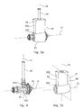
Figure 1 shows a schematic drawing of an azimuth thruster according to one embodiment of the invention, -
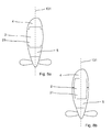
Figure 2a shows a schematic drawing of a pushing azimuth thruster according to one embodiment of the invention, -
Figure 2b shows a schematic drawing of a pulling azimuth thruster according to another embodiment of the invention, -
Figure 3a shows one embodiment of a standardized core unit of an azimuth thruster, -
Figure 3b shows another embodiment of a standardized core unit of an azimuth thruster, -
Figure 4 shows a transmission line contained within the core unit housing, -
Figure 5 shows a pushing azimuth thruster according to one embodiment of the invention, -
Figure 6 shows a pulling azimuth thruster according to another embodiment of the invention, -
Figure 7 shows a schematic drawing illustrating an azimuth thruster having a twisted leading edge, and -
Fig. 8a and 8b show different principles for mounting hydrodynamic elements on the core unit. - With reference to
Fig. 1 , the figure shows anazimuth thruster 1 for propelling avessel 17, such as a ship, a floating production platform or the like. The azimuth thruster has athruster housing 11 around which water flows, and comprises astandardized core unit 2 provided with first and secondhydrodynamic elements propeller 3. Thethruster housing 11 comprises astub part 7 which is adapted for being rotatably mounting on a vessel, and atorpedo part 8 arranged at an opposite end of the stub part. Theazimuth thruster 1 is rotatable about acentre axis 12 by one or moreoperating steering engines 18 provided above the azimuth thruster. Hereby a pulling or pushing force vector of the azimuth thruster can be orientated in a 360 degrees interval about thecentre axis 12 - The
standardized core unit 2 has acore unit housing 21 forming part of thethruster housing 11. A transmission line 6 comprising apropeller shaft 61 and adrive shaft 64 is arranged inside the core unit housing. The transmission line 6 is shown in isolation inFig. 4 . Thedrive shaft 64 extends through the stub part of the thruster housing and into the vessel where it may be operably connected to driving means of the vessel (not shown), such as an onboard combustion engine. Thepropeller shaft 61 extends in alongitudinal direction 13 of the thruster housing and thepropeller 3 is mounted on the drive shaft outside the thruster housing. Thepropeller shaft 61 is driven by apinion gear 632 provided on thedrive shaft 64, cooperating with adrive gear 631 arranged on the propeller shaft. - In another embodiment (not shown) driving means for driving the propeller, such as an electrical motor, may be arranged in the thruster housing of the azimuth thruster. Hereby, the propeller shaft may be directly associated with the driving means, making the drive shaft redundant.
- The standardized core unit shown in further detail in
Fig. 2a andFig. 3b , comprises first 9a and second 9b core unit interfaces defined by exterior surface areas 211 of thecore unit housing 21. Thehydrodynamic elements fig. 2a and Fig. 2b . Various principles for the design of the core unit interfaces and for the mounting of thehydrodynamic elements core unit housing 21 may be envisaged by the skilled person. For example, the hydrodynamic elements may simply abut on thecore unit interfaces Fig. 8a and 8b. Fig. 8a shows an azimuth thruster wherein the hydrodynamic elements partly overlap thecore unit housing 21.Fig. 8b shows an embodiment of the azimuth thruster wherein thestandardized core unit 2 and thus thecore unit housing 21 are enclosed by thehydrodynamic elements core unit housing 21 may be either partly of fully enclosed by the hydrodynamic elements, whereby the hydrodynamic elements may be joined to one another in one exemplary embodiment. - The hydrodynamic elements may be chosen such that the desired hydrodynamic properties of the thruster housing is achieved, but also in accordance with whether the azimuth thruster is a pulling or a pushing azimuth thruster. Hereby, the azimuth thruster is configurable as both a pulling and a pushing azimuth thruster.
- As shown in the figures, the
hydrodynamic elements stub part 7 and thetorpedo part 8 of the thruster housing, thereby having a substantial impact on the hydrodynamic properties of the azimuth thruster. By varying the shape of thehydrodynamic elements - Referring to
Fig. 7 , the hydrodynamic elements may also be used for controlling the t/c-ration of the thruster housing, which is the relationship between the cord length, i.e. the maximum width, Wth of the thruster housing in the longitudinal direction, and the thickness of the thruster housing, i.e. the maximum width of the thruster housing in a transversal direction. - A further effect of the modular design is that the hydrodynamic elements may be used to control the twist of the thruster housing, i.e. the position of a
leading edge 224 of the thruster housing with respect to acentre axis 131 extending in the longitudinal direction of the thruster housing, as shown inFig. 7 . The necessary twist may depend on whether the thruster is a pulling or a pushing thruster, intended speed of the vessel, direction of rotation of the propeller, propeller load, etc. - Referring again to
Fig. 2 , it is shown that atorpedo section 81 of the core unit housing forming part of thetorpedo part 8, is wider in the longitudinal direction, than astub section 71 of the core unit housing forming part of thestub part 7. By using such configuration a distance betweenbearings 62 carrying thepropeller shaft 61 may be increased while keeping the width of the stub part of the core unit housing at a minimum. FromFig. 2b it is also seen that a maximum width, Wcu of the core unit housing in the longitudinal direction is 1/3 to 1/4 of a maximum width, Wth of the thruster housing in the longitudinal direction. - Reducing the width of the core unit housing in general, reduces the impact of the core unit housing on the overall hydrodynamic properties of the thruster housing. A further advantageous effect of the increased width of the
torpedo section 81 of the standardized core unit is that each of thecore unit interfaces -
Fig. 2a andFig. 5 show azimuth thrusters configured as a pushing azimuth thruster indicated by the direction of the arrow. The pushing azimuth thruster has the propeller mounted on a downstream side of the thruster housing. In the embodiment shown inFig 5 , the thruster further comprises apropeller nozzle 15 encircling the propeller to improve operation and propeller effect. -
Fig. 2b andFig. 6 both show azimuth thrusters configured as a pulling azimuth thruster indicated by the direction of the arrow. The pulling azimuth thruster has the propeller mounted on an upstream side of the thruster housing and the thruster may further be provided with afin element 16 extending from the torpedo part in order to increase a total exterior surface area of the thruster housing. - As shown in
Fig. 1 and described above, the azimuth thruster extends from avessel 17 comprising one ormore steering engines 18 for turning the thruster. In one embodiment the steering engine(s) may be an electrical of hydraulic motor cooperating with a gear rim (not shown) provided at an end of thestub part 7 rotatably mounted on the vessel. When dimensioning the mounting for the azimuth thruster including the steering engine, the torque required for turning the azimuth thruster should be considered. The torque required to turn the azimuth thruster depends on several variables such as the hydrodynamic properties of the thruster housing, thruster rotation rate, propeller rotation and vessel speed. In this regardEP1847455A1 discloses an azimuth thruster wherein a pinion gear driving the propeller axis, produces a torque that acts against a resistance torque of the azimuth thruster associated with turning the thruster during operation. Hereby, the torque generated by rotation of the pinion gear is used to counter act the torque resistance of the thruster, thereby reducing the torque required to turn the azimuth thruster during operation. This, in turn, may result in a reduction in the size and/or number of steering engines required to turn the azimuth thruster. - Further, if an azimuth thruster according to the invention is to be used as both a pulling and a pushing azimuth thruster, the skilled person will know that the mounting should be dimensioned according to the forces action on the azimuth thruster when in pull configuration. This is due to the general observation that the torque required to turn a pulling azimuth thruster is larger than the torque required for turning a corresponding pushing azimuth thruster.
- In the following, a method for configuring, i.e. manufacturing from standardized components, embodiments of the above described azimuth thruster will be described in further detail.
- Various embodiments of both pushing and pulling azimuth thrusters having unique hydrodynamic properties may be configured based on the same
standardized core unit 2. To produce an azimuth thruster according to the invention astandardized core unit 2 is provided. Variations of a standardized core unit may exist in that the mount for thepropeller 3 may be provided on either side of thecore unit housing 21, and the composition and dimensioning of the transmission line 6 may vary. Secondly, it is determined whether thespecific azimuth thruster 1 should be of the pushing or the pulling type, and the desired hydrodynamic characteristics are specified. Based on the specified hydrodynamic characteristics of the azimuth thruster, the appropriatehydrodynamic elements - A considerable advantageous effect in this respect is that a
customised azimuth thruster 1 may be build based on standardized components. One advantage of using standardized components is that product variation is introduced late in the end product process. Standardized components can thus be produced before the exact specifications of the future azimuth thrusters are known. Hereby, the production time from order to delivery may be reduced and the use of standardized components may increase quantities. By increasing quantities, a more efficient production process may be utilized. Especially, when it comes to the use of composite or non-metallic materials for the hydrodynamic elements, efficient productions processes are of crucial importance. Making customised azimuth thrusters from composite material without the use of standardized components is very cost ineffective and uncompetitive. In order to be able to use composite or non-metallic materials in azimuth thrusters, it is therefore crucial that standardized components are integrated in the design. - A further advantage of an
azimuth thruster 1 according to the invention is that the azimuth thruster may be re-configured by replacing one or both of thehydrodynamic elements azimuth thruster 1 is mounted, or the pattern of use changes, it may be advantageous to change the hydrodynamic properties of theazimuth thruster 1. In particular, an azimuth thruster according to an embodiment of the invention may be re-configured to alter the twist or the t/c-ration of the thruster housing. Instead of having to install a completely new azimuth thruster on the vessel, the hydrodynamic properties of an azimuth thruster according to the present invention may be changed by simply changing thehydrodynamic elements - As would be readily understood by the person skilled in the art, for an azimuth thruster to be configurable as both a pushing and a pulling azimuth thruster, both the shape of a leading part and a trailing part of the thruster housing must be controllable to arrive at an azimuth thruster having optimal hydrodynamic properties. This is achieved by the present invention by the use of hydrodynamic elements arranged on both sides of the core unit housing.
- Although the present invention has been described in connection with the specified embodiments, it should not be construed as being in any way limited to the presented examples. The scope of the present invention is set out by the accompanying claim set. In the context of the claims, the terms "comprising" or "comprises" do not exclude other possible elements or steps. Also, the mentioning of references such as "a" or "an" etc. should not be construed as excluding a plurality. The use of reference signs in the claims with respect to elements indicated in the figures shall also not be construed as limiting the scope of the invention. Furthermore, individual features mentioned in different claims, may possibly be advantageously combined, and the mentioning of these features in different claims does not exclude that a combination of features is not possible and advantageous.
Claims (15)
- An azimuth thruster (1) for propelling a vessel, having a thruster housing (11) around which water flows, and comprising:- a standardized core unit (2) having a core unit housing (21) forming part of the thruster housing,- a transmission line (6) arranged within in the core unit housing, comprising a propeller shaft (61) extending in a longitudinal direction (13) of the thruster housing, and- a propeller (3) arranged outside the thruster housing and being operationally connected to the propeller shaft,
wherein, the azimuth thruster is configurable as both a pulling azimuth thruster and a pushing azimuth thruster by comprising first and second hydrodynamic elements (4,5) mounted on matching first (9a) and second (9b) core unit interfaces defined by exterior surface areas (211) of the core unit housing, the hydrodynamic elements forming part of the thruster housing to control the flow of water around the thruster housing, and the core unit interfaces being adapted for receiving different hydrodynamic elements having different hydrodynamic properties. - An azimuth thruster according to claim 1, wherein the transmission line further comprises bearings (62) and gears (63), all of which are fully contained within the core unit housing.
- An azimuth thruster according to any of claims 1 or 2, wherein the thruster housing comprises a stub part (7), one end of which is adapted for being rotatably mounting on a vessel, and a torpedo part (8) arranged at an opposite end of the stub part, and wherein the hydrodynamic elements constitute a part of both the stub part and of the torpedo part.
- An azimuth thruster according to any of the preceding claims, wherein a torpedo section (81) of the core unit housing forming part of the torpedo part, is wider than a stub section (71) of the core unit housing forming part of the stub part in the longitudinal direction of the thruster housing.
- An azimuth thruster according to any of the preceding claims, wherein each of the core unit interfaces are defined by one or more end faces (222) of the core unit housing.
- An azimuth thruster according to any of the preceding claims, wherein the core unit housing is symmetrical about a plane of symmetry (14) intersecting a centre axis (12) of the core unit housing and extending in a direction transversal to the longitudinal direction of the thruster housing.
- An azimuth thruster according any of the preceding claims, wherein the core unit housing is adapted for providing the structural integrity of the azimuth thruster by absorbing structural loads and bearing loads induced by the weight and operation of the azimuth thruster itself and hydro induced forces acting on the thruster housing during use.
- An azimuth thruster according to any of the preceding claims, wherein the hydrodynamic elements are made from non-metallic materials, such as composites, polymers, glass- or carbon fibre reinforced polymers or polyurethane.
- An azimuth thruster according to any of the preceding claims, wherein the hydrodynamic elements partly overlap or enclose the standardized core unit.
- An azimuth thruster according to any of the preceding claims, wherein a maximum width, Wcu of the core unit housing in the longitudinal direction is 1/3 to 1/4 of a maximum width, Wth of the thruster housing in the longitudinal direction.
- An azimuth thruster according to any of the preceding claims, wherein a t/c-ration of the thruster housing is configurable in the range from 0,2 to 0,6.
- An azimuth thruster according to any of the preceding claims, wherein a width of the torpedo part of the core unit housing in the longitudinal direction is 12-17 times the diameter of the propeller shaft.
- A vessel comprising an azimuth thruster according to any of the preceding claims.
- A method for configuring or re-configuring the hydrodynamic characteristics of an azimuth thruster according to any of claims 1-12, comprising the steps of:- providing a standardized core unit- specifying hydrodynamic characteristics of the azimuth thruster,- mounting hydrodynamic elements on the standardized core unit to meet the specified hydrodynamic characteristics.
- A method according to claim 14, further comprising the step of:- replacing a first and/or a second hydrodynamic element already mounted on the standardized core unit with a third and/or a fourth hydrodynamic element having different hydrodynamic properties.
Priority Applications (23)
| Application Number | Priority Date | Filing Date | Title |
|---|---|---|---|
| ES17174327T ES2719730T3 (en) | 2013-09-24 | 2013-09-24 | Modular Azimuthal Propulsion |
| DK13185723.7T DK2851280T3 (en) | 2013-09-24 | 2013-09-24 | Modular azimuth thruster |
| PL13185723T PL2851280T3 (en) | 2013-09-24 | 2013-09-24 | Modular azimuth thruster |
| DK17174327.1T DK3241737T3 (en) | 2013-09-24 | 2013-09-24 | MODULAR AZIMUTH-THRUSTER |
| EP13185723.7A EP2851280B1 (en) | 2013-09-24 | 2013-09-24 | Modular azimuth thruster |
| PT131857237T PT2851280T (en) | 2013-09-24 | 2013-09-24 | Modular azimuth thruster |
| PT17174327T PT3241737T (en) | 2013-09-24 | 2013-09-24 | Modular azimuth thruster |
| ES13185723.7T ES2639853T3 (en) | 2013-09-24 | 2013-09-24 | Modular Azimuthal Propulsion |
| EP17174327.1A EP3241737B1 (en) | 2013-09-24 | 2013-09-24 | Modular azimuth thruster |
| PL17174327T PL3241737T3 (en) | 2013-09-24 | 2013-09-24 | Modular azimuth thruster |
| KR1020197028388A KR102250476B1 (en) | 2013-09-24 | 2014-09-24 | Modular azimuth thruster |
| BR112016006212-4A BR112016006212B1 (en) | 2013-09-24 | 2014-09-24 | AZIMUTAL PROPELLER FOR VESSEL PROPULSION, VESSEL WITH AZIMUTAL PROPELLER AND METHOD FOR SETTING OR RESETTING THE HYDRODYNAMIC CHARACTERISTICS OF AN AZIMUTHAL Thruster |
| CN201480052244.2A CN105612103B (en) | 2013-09-24 | 2014-09-24 | modular azimuth thruster |
| KR1020167009826A KR102250475B1 (en) | 2013-09-24 | 2014-09-24 | Modular azimuth thruster |
| JP2016517493A JP6583924B2 (en) | 2013-09-24 | 2014-09-24 | Modular azimuth thruster |
| RU2016115596A RU2660202C2 (en) | 2013-09-24 | 2014-09-24 | Azimuth thruster |
| US15/024,162 US9868498B2 (en) | 2013-09-24 | 2014-09-24 | Modular azimuth thruster |
| SG11201601248QA SG11201601248QA (en) | 2013-09-24 | 2014-09-24 | Modular azimuth thruster |
| PCT/EP2014/070295 WO2015044160A1 (en) | 2013-09-24 | 2014-09-24 | Modular azimuth thruster |
| HK15109442.8A HK1208654A1 (en) | 2013-09-24 | 2015-09-24 | Modular azimuth thruster |
| HRP20171328TT HRP20171328T1 (en) | 2013-09-24 | 2017-09-04 | Modular azimuth thruster |
| US15/871,355 US10549830B2 (en) | 2013-09-24 | 2018-01-15 | Modular azimuth thruster |
| HRP20190662TT HRP20190662T1 (en) | 2013-09-24 | 2019-04-08 | Modular azimuth thruster |
Applications Claiming Priority (1)
| Application Number | Priority Date | Filing Date | Title |
|---|---|---|---|
| EP13185723.7A EP2851280B1 (en) | 2013-09-24 | 2013-09-24 | Modular azimuth thruster |
Related Child Applications (1)
| Application Number | Title | Priority Date | Filing Date |
|---|---|---|---|
| EP17174327.1A Division EP3241737B1 (en) | 2013-09-24 | 2013-09-24 | Modular azimuth thruster |
Publications (2)
| Publication Number | Publication Date |
|---|---|
| EP2851280A1 true EP2851280A1 (en) | 2015-03-25 |
| EP2851280B1 EP2851280B1 (en) | 2017-06-07 |
Family
ID=49274412
Family Applications (2)
| Application Number | Title | Priority Date | Filing Date |
|---|---|---|---|
| EP13185723.7A Active EP2851280B1 (en) | 2013-09-24 | 2013-09-24 | Modular azimuth thruster |
| EP17174327.1A Active EP3241737B1 (en) | 2013-09-24 | 2013-09-24 | Modular azimuth thruster |
Family Applications After (1)
| Application Number | Title | Priority Date | Filing Date |
|---|---|---|---|
| EP17174327.1A Active EP3241737B1 (en) | 2013-09-24 | 2013-09-24 | Modular azimuth thruster |
Country Status (15)
| Country | Link |
|---|---|
| US (2) | US9868498B2 (en) |
| EP (2) | EP2851280B1 (en) |
| JP (1) | JP6583924B2 (en) |
| KR (2) | KR102250475B1 (en) |
| CN (1) | CN105612103B (en) |
| BR (1) | BR112016006212B1 (en) |
| DK (2) | DK2851280T3 (en) |
| ES (2) | ES2639853T3 (en) |
| HK (1) | HK1208654A1 (en) |
| HR (2) | HRP20171328T1 (en) |
| PL (2) | PL3241737T3 (en) |
| PT (2) | PT3241737T (en) |
| RU (1) | RU2660202C2 (en) |
| SG (1) | SG11201601248QA (en) |
| WO (1) | WO2015044160A1 (en) |
Cited By (2)
| Publication number | Priority date | Publication date | Assignee | Title |
|---|---|---|---|---|
| EP3241737A1 (en) * | 2013-09-24 | 2017-11-08 | Rolls-Royce Marine AS | Modular azimuth thruster |
| KR20180134991A (en) * | 2016-05-18 | 2018-12-19 | 에이비비 오와이 | Method and apparatus for controlling vibration of a ship propulsion system |
Families Citing this family (10)
| Publication number | Priority date | Publication date | Assignee | Title |
|---|---|---|---|---|
| USD791678S1 (en) * | 2015-08-20 | 2017-07-11 | Abb Schweiz Ag | Propulsion unit for ships and boats |
| DE102015219657A1 (en) * | 2015-10-09 | 2017-04-13 | Hochschule Flensburg | Drive device, in particular for a watercraft |
| ES2709984T3 (en) * | 2016-04-25 | 2019-04-22 | Aetc Sapphire | Watercraft propulsion unit comprising a mobile crankcase and a hydraulic fluid conditioning module |
| NL2018388B1 (en) * | 2017-02-16 | 2018-09-06 | Veth Propulsion B V | Thruster for propelling a watercraft |
| CN107298160A (en) * | 2017-05-18 | 2017-10-27 | 苏州横海信息科技有限公司 | Ship's propeller |
| KR102006892B1 (en) * | 2017-11-07 | 2019-10-01 | 삼성중공업 주식회사 | Insert installation type self containing thruster |
| GB201817933D0 (en) * | 2018-11-02 | 2018-12-19 | Rolls Royce Plc | Calibrating an engine core |
| CN109850081A (en) * | 2019-03-15 | 2019-06-07 | 中国海洋大学 | The more floating bodies of sail power-assisted link nobody carrying platform waterborne and control method |
| NO20190359A1 (en) * | 2019-03-18 | 2020-09-21 | Seadrive As | A drive device for a vessel |
| CN110498007B (en) * | 2019-09-03 | 2021-08-20 | 中船黄埔文冲船舶有限公司 | Installation method for inverted installation and lateral pushing of horizontal sectional material |
Citations (5)
| Publication number | Priority date | Publication date | Assignee | Title |
|---|---|---|---|---|
| FR2798184A1 (en) * | 1999-09-07 | 2001-03-09 | Guy Fontanille | PROPULSION ENGINE ANGLE RETURN DEVICE CASTER FOR BOAT |
| WO2002026558A1 (en) * | 2000-09-25 | 2002-04-04 | Abb Oy | A ship's propulsion arrangement as well as a method and means related thereto |
| US20070173140A1 (en) * | 2006-01-20 | 2007-07-26 | Torqeedo Gmbh | Integrated Outboard Motor |
| EP1847455A1 (en) | 2006-04-20 | 2007-10-24 | Rolls-Royce Marine AS | A propulsion and steering unit for a waterborne vessel |
| US20110318978A1 (en) * | 2009-03-02 | 2011-12-29 | Siemens Aktiengesellschaft | Modular gondola drive for a floating device |
Family Cites Families (23)
| Publication number | Priority date | Publication date | Assignee | Title |
|---|---|---|---|---|
| US3799291A (en) | 1971-03-05 | 1974-03-26 | Schottel Werft | Lubricating device for a z-drive for ships |
| DE3246730A1 (en) * | 1982-12-17 | 1984-06-20 | Licentia Patent-Verwaltungs-Gmbh, 6000 Frankfurt | ELECTRICALLY DRIVEN SCREW |
| JPS59179293A (en) | 1983-03-30 | 1984-10-11 | Nippon Steel Corp | Flux cored wire for welding |
| JPS59179293U (en) * | 1983-05-18 | 1984-11-30 | 石川島播磨重工業株式会社 | propeller device |
| GB8401879D0 (en) * | 1984-01-25 | 1984-02-29 | Vickers Plc | Vessel |
| JP2584678B2 (en) * | 1988-11-18 | 1997-02-26 | 日本鋼管株式会社 | Open channel cleaning system |
| RU2115589C1 (en) * | 1996-06-25 | 1998-07-20 | Государственный научно-исследовательский и проектно-конструкторский институт по развитию и эксплуатации флота "Гипрорыбфлот" | Shipboard propulsion engine plant, type swinging propeller |
| KR100933096B1 (en) * | 2001-08-30 | 2009-12-21 | 지멘스 악티엔게젤샤프트 | Navy Ship Superconductors |
| FR2869586B1 (en) * | 2004-04-30 | 2006-06-16 | Alstom Sa | PROPULSION ASSEMBLY FOR SHIP, COMPRISING A NACELLE FOR AN INSTALLATION UNDER THE CARINE OF THE VESSEL |
| NO335597B1 (en) * | 2005-11-30 | 2015-01-12 | Rolls Royce Marine As | Device for storing a propulsion unit and a propulsion unit for a marine vessel |
| KR100972154B1 (en) * | 2007-07-25 | 2010-07-26 | 삼성중공업 주식회사 | Icebreaking extra propulsion system and icebreaking ship |
| JP5100370B2 (en) | 2007-12-28 | 2012-12-19 | 川崎重工業株式会社 | Thrust generator |
| CN201189954Y (en) * | 2008-04-28 | 2009-02-04 | 江苏华阳科技开发有限公司 | Sealing apparatus at lifting position of full rotary electric propeller with expansion under water for boat |
| KR101574822B1 (en) * | 2008-08-27 | 2015-12-04 | 아크티에볼라게트 에스케이에프 | Bearings for pod propulsion system |
| NO331651B1 (en) * | 2009-05-20 | 2012-02-13 | Rolls Royce Marine As | Storage of propeller unit for a vessel |
| NL2003946C2 (en) * | 2009-12-11 | 2011-06-15 | Marifin Beheer B V | BEARING CONSTRUCTION, AND A SCREW EQUIPPED WITH SUCH A BEARING CONSTRUCTION. |
| JP2012116248A (en) * | 2010-11-29 | 2012-06-21 | Mitsubishi Heavy Ind Ltd | Azimuth propeller, control method thereof and ship having the same |
| JP5395829B2 (en) | 2011-02-25 | 2014-01-22 | 富士フイルム株式会社 | Endoscope device |
| NL2006678C2 (en) * | 2011-04-28 | 2012-10-30 | Imc Corporate Licensing B V | POD WITH REDUCTION DRIVE. |
| KR20130023863A (en) | 2011-08-30 | 2013-03-08 | 현대중공업 주식회사 | Oil circulation structure of azimuth thruster |
| JP5872255B2 (en) * | 2011-11-08 | 2016-03-01 | ヤマハ発動機株式会社 | Ship propulsion device |
| CN102632982A (en) | 2012-04-28 | 2012-08-15 | 中国船舶重工集团公司第七○二研究所 | Shaftless driven type integrated motor propeller |
| PT3241737T (en) * | 2013-09-24 | 2019-05-09 | Rolls Royce Marine As | Modular azimuth thruster |
-
2013
- 2013-09-24 PT PT17174327T patent/PT3241737T/en unknown
- 2013-09-24 PL PL17174327T patent/PL3241737T3/en unknown
- 2013-09-24 ES ES13185723.7T patent/ES2639853T3/en active Active
- 2013-09-24 EP EP13185723.7A patent/EP2851280B1/en active Active
- 2013-09-24 PL PL13185723T patent/PL2851280T3/en unknown
- 2013-09-24 ES ES17174327T patent/ES2719730T3/en active Active
- 2013-09-24 DK DK13185723.7T patent/DK2851280T3/en active
- 2013-09-24 EP EP17174327.1A patent/EP3241737B1/en active Active
- 2013-09-24 PT PT131857237T patent/PT2851280T/en unknown
- 2013-09-24 DK DK17174327.1T patent/DK3241737T3/en active
-
2014
- 2014-09-24 KR KR1020167009826A patent/KR102250475B1/en active IP Right Grant
- 2014-09-24 RU RU2016115596A patent/RU2660202C2/en active
- 2014-09-24 US US15/024,162 patent/US9868498B2/en active Active
- 2014-09-24 JP JP2016517493A patent/JP6583924B2/en active Active
- 2014-09-24 WO PCT/EP2014/070295 patent/WO2015044160A1/en active Application Filing
- 2014-09-24 KR KR1020197028388A patent/KR102250476B1/en active IP Right Grant
- 2014-09-24 SG SG11201601248QA patent/SG11201601248QA/en unknown
- 2014-09-24 CN CN201480052244.2A patent/CN105612103B/en active Active
- 2014-09-24 BR BR112016006212-4A patent/BR112016006212B1/en active IP Right Grant
-
2015
- 2015-09-24 HK HK15109442.8A patent/HK1208654A1/en unknown
-
2017
- 2017-09-04 HR HRP20171328TT patent/HRP20171328T1/en unknown
-
2018
- 2018-01-15 US US15/871,355 patent/US10549830B2/en active Active
-
2019
- 2019-04-08 HR HRP20190662TT patent/HRP20190662T1/en unknown
Patent Citations (5)
| Publication number | Priority date | Publication date | Assignee | Title |
|---|---|---|---|---|
| FR2798184A1 (en) * | 1999-09-07 | 2001-03-09 | Guy Fontanille | PROPULSION ENGINE ANGLE RETURN DEVICE CASTER FOR BOAT |
| WO2002026558A1 (en) * | 2000-09-25 | 2002-04-04 | Abb Oy | A ship's propulsion arrangement as well as a method and means related thereto |
| US20070173140A1 (en) * | 2006-01-20 | 2007-07-26 | Torqeedo Gmbh | Integrated Outboard Motor |
| EP1847455A1 (en) | 2006-04-20 | 2007-10-24 | Rolls-Royce Marine AS | A propulsion and steering unit for a waterborne vessel |
| US20110318978A1 (en) * | 2009-03-02 | 2011-12-29 | Siemens Aktiengesellschaft | Modular gondola drive for a floating device |
Cited By (4)
| Publication number | Priority date | Publication date | Assignee | Title |
|---|---|---|---|---|
| EP3241737A1 (en) * | 2013-09-24 | 2017-11-08 | Rolls-Royce Marine AS | Modular azimuth thruster |
| KR20180134991A (en) * | 2016-05-18 | 2018-12-19 | 에이비비 오와이 | Method and apparatus for controlling vibration of a ship propulsion system |
| JP2019516615A (en) * | 2016-05-18 | 2019-06-20 | エービービー オサケ ユキチュア | Method and control device for controlling vibrations of a propulsion unit of a ship |
| US10894590B2 (en) | 2016-05-18 | 2021-01-19 | Abb Oy | Method and a control arrangement for controlling vibrations of a propulsion unit of a vessel |
Also Published As
Similar Documents
| Publication | Publication Date | Title |
|---|---|---|
| EP2851280B1 (en) | Modular azimuth thruster | |
| EP3142921B1 (en) | Propulsion unit | |
| EP2944558A1 (en) | Oscillating foil propulsion system and method for controlling a motion of an oscillating movable foil | |
| CN100348458C (en) | Fish shape simulating nacelle propeller | |
| CN104955724A (en) | Propulsion unit for maritime vessel including a nozzle exhibiting an exchangeable leading edge on the inlet of the nozzle | |
| CN104859820A (en) | Propeller for two-stage duct type boat | |
| EP3645385A1 (en) | Propeller pump-type hydraulic propulsion device and vessel equipped with such a device | |
| CN110562421A (en) | Ducted helical drum propeller and lateral control valve system | |
| EP3088295B1 (en) | Modular propulsion unit nozzle | |
| CN102101526B (en) | underwater vortex propeller | |
| US8388391B1 (en) | Screw conveyor shape propeller | |
| FI130447B (en) | Marine propeller | |
| RU2708696C1 (en) | Screw propeller of screw-steering column of water vessel and screw-steering column with said screw propeller | |
| RU119718U1 (en) | THRUSTER | |
| CN210455161U (en) | Multistage propeller ship propulsion device | |
| KR20150029666A (en) | propulsive equipments integrated blade and casing and propulsion method using it | |
| Rubinraut | Ships With Highly Efficient Propulsion System |
Legal Events
| Date | Code | Title | Description |
|---|---|---|---|
| PUAI | Public reference made under article 153(3) epc to a published international application that has entered the european phase |
Free format text: ORIGINAL CODE: 0009012 |
|
| 17P | Request for examination filed |
Effective date: 20130924 |
|
| AK | Designated contracting states |
Kind code of ref document: A1 Designated state(s): AL AT BE BG CH CY CZ DE DK EE ES FI FR GB GR HR HU IE IS IT LI LT LU LV MC MK MT NL NO PL PT RO RS SE SI SK SM TR |
|
| AX | Request for extension of the european patent |
Extension state: BA ME |
|
| R17P | Request for examination filed (corrected) |
Effective date: 20150924 |
|
| RAX | Requested extension states of the european patent have changed |
Extension state: ME Payment date: 20150924 Extension state: BA Payment date: 20150924 |
|
| RBV | Designated contracting states (corrected) |
Designated state(s): AL AT BE BG CH CY CZ DE DK EE ES FI FR GB GR HR HU IE IS IT LI LT LU LV MC MK MT NL NO PL PT RO RS SE SI SK SM TR |
|
| REG | Reference to a national code |
Ref country code: HK Ref legal event code: DE Ref document number: 1208654 Country of ref document: HK |
|
| GRAP | Despatch of communication of intention to grant a patent |
Free format text: ORIGINAL CODE: EPIDOSNIGR1 |
|
| INTG | Intention to grant announced |
Effective date: 20161201 |
|
| GRAS | Grant fee paid |
Free format text: ORIGINAL CODE: EPIDOSNIGR3 |
|
| GRAJ | Information related to disapproval of communication of intention to grant by the applicant or resumption of examination proceedings by the epo deleted |
Free format text: ORIGINAL CODE: EPIDOSDIGR1 |
|
| GRAL | Information related to payment of fee for publishing/printing deleted |
Free format text: ORIGINAL CODE: EPIDOSDIGR3 |
|
| GRAR | Information related to intention to grant a patent recorded |
Free format text: ORIGINAL CODE: EPIDOSNIGR71 |
|
| INTC | Intention to grant announced (deleted) | ||
| RAP1 | Party data changed (applicant data changed or rights of an application transferred) |
Owner name: ROLLS-ROYCE MARINE AS |
|
| AK | Designated contracting states |
Kind code of ref document: B1 Designated state(s): AL AT BE BG CH CY CZ DE DK EE ES FI FR GB GR HR HU IE IS IT LI LT LU LV MC MK MT NL NO PL PT RO RS SE SI SK SM TR |
|
| AX | Request for extension of the european patent |
Extension state: BA ME |
|
| INTG | Intention to grant announced |
Effective date: 20170502 |
|
| REG | Reference to a national code |
Ref country code: GB Ref legal event code: FG4D |
|
| GRAA | (expected) grant |
Free format text: ORIGINAL CODE: 0009210 |
|
| REG | Reference to a national code |
Ref country code: CH Ref legal event code: EP Ref country code: AT Ref legal event code: REF Ref document number: 899018 Country of ref document: AT Kind code of ref document: T Effective date: 20170615 |
|
| REG | Reference to a national code |
Ref country code: IE Ref legal event code: FG4D |
|
| REG | Reference to a national code |
Ref country code: DE Ref legal event code: R096 Ref document number: 602013021916 Country of ref document: DE |
|
| REG | Reference to a national code |
Ref country code: HR Ref legal event code: TUEP Ref document number: P20171328 Country of ref document: HR |
|
| REG | Reference to a national code |
Ref country code: RO Ref legal event code: EPE |
|
| REG | Reference to a national code |
Ref country code: PT Ref legal event code: SC4A Ref document number: 2851280 Country of ref document: PT Date of ref document: 20170911 Kind code of ref document: T Free format text: AVAILABILITY OF NATIONAL TRANSLATION Effective date: 20170905 |
|
| REG | Reference to a national code |
Ref country code: NL Ref legal event code: FP |
|
| REG | Reference to a national code |
Ref country code: DK Ref legal event code: T3 Effective date: 20170919 Ref country code: FR Ref legal event code: PLFP Year of fee payment: 5 |
|
| REG | Reference to a national code |
Ref country code: SE Ref legal event code: TRGR |
|
| REG | Reference to a national code |
Ref country code: LT Ref legal event code: MG4D |
|
| REG | Reference to a national code |
Ref country code: ES Ref legal event code: FG2A Ref document number: 2639853 Country of ref document: ES Kind code of ref document: T3 Effective date: 20171030 |
|
| PG25 | Lapsed in a contracting state [announced via postgrant information from national office to epo] |
Ref country code: LT Free format text: LAPSE BECAUSE OF FAILURE TO SUBMIT A TRANSLATION OF THE DESCRIPTION OR TO PAY THE FEE WITHIN THE PRESCRIBED TIME-LIMIT Effective date: 20170607 |
|
| REG | Reference to a national code |
Ref country code: AT Ref legal event code: MK05 Ref document number: 899018 Country of ref document: AT Kind code of ref document: T Effective date: 20170607 |
|
| REG | Reference to a national code |
Ref country code: NO Ref legal event code: T2 Effective date: 20170607 |
|
| PG25 | Lapsed in a contracting state [announced via postgrant information from national office to epo] |
Ref country code: LV Free format text: LAPSE BECAUSE OF FAILURE TO SUBMIT A TRANSLATION OF THE DESCRIPTION OR TO PAY THE FEE WITHIN THE PRESCRIBED TIME-LIMIT Effective date: 20170607 Ref country code: RS Free format text: LAPSE BECAUSE OF FAILURE TO SUBMIT A TRANSLATION OF THE DESCRIPTION OR TO PAY THE FEE WITHIN THE PRESCRIBED TIME-LIMIT Effective date: 20170607 Ref country code: BG Free format text: LAPSE BECAUSE OF FAILURE TO SUBMIT A TRANSLATION OF THE DESCRIPTION OR TO PAY THE FEE WITHIN THE PRESCRIBED TIME-LIMIT Effective date: 20170907 |
|
| REG | Reference to a national code |
Ref country code: HR Ref legal event code: T1PR Ref document number: P20171328 Country of ref document: HR |
|
| PG25 | Lapsed in a contracting state [announced via postgrant information from national office to epo] |
Ref country code: CZ Free format text: LAPSE BECAUSE OF FAILURE TO SUBMIT A TRANSLATION OF THE DESCRIPTION OR TO PAY THE FEE WITHIN THE PRESCRIBED TIME-LIMIT Effective date: 20170607 Ref country code: AT Free format text: LAPSE BECAUSE OF FAILURE TO SUBMIT A TRANSLATION OF THE DESCRIPTION OR TO PAY THE FEE WITHIN THE PRESCRIBED TIME-LIMIT Effective date: 20170607 Ref country code: EE Free format text: LAPSE BECAUSE OF FAILURE TO SUBMIT A TRANSLATION OF THE DESCRIPTION OR TO PAY THE FEE WITHIN THE PRESCRIBED TIME-LIMIT Effective date: 20170607 Ref country code: SK Free format text: LAPSE BECAUSE OF FAILURE TO SUBMIT A TRANSLATION OF THE DESCRIPTION OR TO PAY THE FEE WITHIN THE PRESCRIBED TIME-LIMIT Effective date: 20170607 |
|
| PG25 | Lapsed in a contracting state [announced via postgrant information from national office to epo] |
Ref country code: IS Free format text: LAPSE BECAUSE OF FAILURE TO SUBMIT A TRANSLATION OF THE DESCRIPTION OR TO PAY THE FEE WITHIN THE PRESCRIBED TIME-LIMIT Effective date: 20171007 Ref country code: SM Free format text: LAPSE BECAUSE OF FAILURE TO SUBMIT A TRANSLATION OF THE DESCRIPTION OR TO PAY THE FEE WITHIN THE PRESCRIBED TIME-LIMIT Effective date: 20170607 |
|
| REG | Reference to a national code |
Ref country code: DE Ref legal event code: R097 Ref document number: 602013021916 Country of ref document: DE |
|
| REG | Reference to a national code |
Ref country code: GR Ref legal event code: EP Ref document number: 20170402402 Country of ref document: GR Effective date: 20180309 |
|
| PLBE | No opposition filed within time limit |
Free format text: ORIGINAL CODE: 0009261 |
|
| STAA | Information on the status of an ep patent application or granted ep patent |
Free format text: STATUS: NO OPPOSITION FILED WITHIN TIME LIMIT |
|
| REG | Reference to a national code |
Ref country code: CH Ref legal event code: PL |
|
| 26N | No opposition filed |
Effective date: 20180308 |
|
| PG25 | Lapsed in a contracting state [announced via postgrant information from national office to epo] |
Ref country code: MC Free format text: LAPSE BECAUSE OF FAILURE TO SUBMIT A TRANSLATION OF THE DESCRIPTION OR TO PAY THE FEE WITHIN THE PRESCRIBED TIME-LIMIT Effective date: 20170607 Ref country code: SI Free format text: LAPSE BECAUSE OF FAILURE TO SUBMIT A TRANSLATION OF THE DESCRIPTION OR TO PAY THE FEE WITHIN THE PRESCRIBED TIME-LIMIT Effective date: 20170607 |
|
| REG | Reference to a national code |
Ref country code: IE Ref legal event code: MM4A |
|
| REG | Reference to a national code |
Ref country code: BE Ref legal event code: MM Effective date: 20170930 |
|
| PG25 | Lapsed in a contracting state [announced via postgrant information from national office to epo] |
Ref country code: LU Free format text: LAPSE BECAUSE OF NON-PAYMENT OF DUE FEES Effective date: 20170924 |
|
| PG25 | Lapsed in a contracting state [announced via postgrant information from national office to epo] |
Ref country code: CH Free format text: LAPSE BECAUSE OF NON-PAYMENT OF DUE FEES Effective date: 20170930 Ref country code: LI Free format text: LAPSE BECAUSE OF NON-PAYMENT OF DUE FEES Effective date: 20170930 Ref country code: IE Free format text: LAPSE BECAUSE OF NON-PAYMENT OF DUE FEES Effective date: 20170924 |
|
| PG25 | Lapsed in a contracting state [announced via postgrant information from national office to epo] |
Ref country code: BE Free format text: LAPSE BECAUSE OF NON-PAYMENT OF DUE FEES Effective date: 20170930 |
|
| REG | Reference to a national code |
Ref country code: FR Ref legal event code: PLFP Year of fee payment: 6 |
|
| PG25 | Lapsed in a contracting state [announced via postgrant information from national office to epo] |
Ref country code: MT Free format text: LAPSE BECAUSE OF NON-PAYMENT OF DUE FEES Effective date: 20170924 |
|
| PG25 | Lapsed in a contracting state [announced via postgrant information from national office to epo] |
Ref country code: HU Free format text: LAPSE BECAUSE OF FAILURE TO SUBMIT A TRANSLATION OF THE DESCRIPTION OR TO PAY THE FEE WITHIN THE PRESCRIBED TIME-LIMIT; INVALID AB INITIO Effective date: 20130924 |
|
| REG | Reference to a national code |
Ref country code: HR Ref legal event code: ODRP Ref document number: P20171328 Country of ref document: HR Payment date: 20190903 Year of fee payment: 7 |
|
| PG25 | Lapsed in a contracting state [announced via postgrant information from national office to epo] |
Ref country code: CY Free format text: LAPSE BECAUSE OF FAILURE TO SUBMIT A TRANSLATION OF THE DESCRIPTION OR TO PAY THE FEE WITHIN THE PRESCRIBED TIME-LIMIT Effective date: 20170607 |
|
| PG25 | Lapsed in a contracting state [announced via postgrant information from national office to epo] |
Ref country code: MK Free format text: LAPSE BECAUSE OF FAILURE TO SUBMIT A TRANSLATION OF THE DESCRIPTION OR TO PAY THE FEE WITHIN THE PRESCRIBED TIME-LIMIT Effective date: 20170607 |
|
| PG25 | Lapsed in a contracting state [announced via postgrant information from national office to epo] |
Ref country code: AL Free format text: LAPSE BECAUSE OF FAILURE TO SUBMIT A TRANSLATION OF THE DESCRIPTION OR TO PAY THE FEE WITHIN THE PRESCRIBED TIME-LIMIT Effective date: 20170607 |
|
| REG | Reference to a national code |
Ref country code: HR Ref legal event code: ODRP Ref document number: P20171328 Country of ref document: HR Payment date: 20200915 Year of fee payment: 8 |
|
| REG | Reference to a national code |
Ref country code: HR Ref legal event code: ODRP Ref document number: P20171328 Country of ref document: HR Payment date: 20210920 Year of fee payment: 9 |
|
| REG | Reference to a national code |
Ref country code: HK Ref legal event code: WD Ref document number: 1208654 Country of ref document: HK |
|
| REG | Reference to a national code |
Ref country code: HR Ref legal event code: ODRP Ref document number: P20171328 Country of ref document: HR Payment date: 20220919 Year of fee payment: 10 |
|
| P01 | Opt-out of the competence of the unified patent court (upc) registered |
Effective date: 20230526 |
|
| REG | Reference to a national code |
Ref country code: HR Ref legal event code: ODRP Ref document number: P20171328 Country of ref document: HR Payment date: 20230918 Year of fee payment: 11 |
|
| PGFP | Annual fee paid to national office [announced via postgrant information from national office to epo] |
Ref country code: TR Payment date: 20230921 Year of fee payment: 11 Ref country code: RO Payment date: 20230920 Year of fee payment: 11 Ref country code: NO Payment date: 20230922 Year of fee payment: 11 Ref country code: NL Payment date: 20230920 Year of fee payment: 11 Ref country code: GB Payment date: 20230920 Year of fee payment: 11 Ref country code: FI Payment date: 20230920 Year of fee payment: 11 |
|
| PGFP | Annual fee paid to national office [announced via postgrant information from national office to epo] |
Ref country code: SE Payment date: 20230920 Year of fee payment: 11 Ref country code: PT Payment date: 20230914 Year of fee payment: 11 Ref country code: PL Payment date: 20230919 Year of fee payment: 11 Ref country code: HR Payment date: 20230918 Year of fee payment: 11 Ref country code: GR Payment date: 20230921 Year of fee payment: 11 Ref country code: FR Payment date: 20230928 Year of fee payment: 11 Ref country code: DK Payment date: 20230925 Year of fee payment: 11 Ref country code: DE Payment date: 20230920 Year of fee payment: 11 |
|
| PGFP | Annual fee paid to national office [announced via postgrant information from national office to epo] |
Ref country code: ES Payment date: 20231124 Year of fee payment: 11 |
|
| PGFP | Annual fee paid to national office [announced via postgrant information from national office to epo] |
Ref country code: IT Payment date: 20230927 Year of fee payment: 11 |