EP2851259B1 - Method for manufacturing a cover for air conditioning device for vehicle - Google Patents
Method for manufacturing a cover for air conditioning device for vehicle Download PDFInfo
- Publication number
- EP2851259B1 EP2851259B1 EP13791701.9A EP13791701A EP2851259B1 EP 2851259 B1 EP2851259 B1 EP 2851259B1 EP 13791701 A EP13791701 A EP 13791701A EP 2851259 B1 EP2851259 B1 EP 2851259B1
- Authority
- EP
- European Patent Office
- Prior art keywords
- core
- resin
- cover
- fibers
- molding die
- Prior art date
- Legal status (The legal status is an assumption and is not a legal conclusion. Google has not performed a legal analysis and makes no representation as to the accuracy of the status listed.)
- Active
Links
Images


Classifications
-
- B—PERFORMING OPERATIONS; TRANSPORTING
- B29—WORKING OF PLASTICS; WORKING OF SUBSTANCES IN A PLASTIC STATE IN GENERAL
- B29C—SHAPING OR JOINING OF PLASTICS; SHAPING OF MATERIAL IN A PLASTIC STATE, NOT OTHERWISE PROVIDED FOR; AFTER-TREATMENT OF THE SHAPED PRODUCTS, e.g. REPAIRING
- B29C70/00—Shaping composites, i.e. plastics material comprising reinforcements, fillers or preformed parts, e.g. inserts
- B29C70/68—Shaping composites, i.e. plastics material comprising reinforcements, fillers or preformed parts, e.g. inserts by incorporating or moulding on preformed parts, e.g. inserts or layers, e.g. foam blocks
- B29C70/78—Moulding material on one side only of the preformed part
-
- B—PERFORMING OPERATIONS; TRANSPORTING
- B29—WORKING OF PLASTICS; WORKING OF SUBSTANCES IN A PLASTIC STATE IN GENERAL
- B29C—SHAPING OR JOINING OF PLASTICS; SHAPING OF MATERIAL IN A PLASTIC STATE, NOT OTHERWISE PROVIDED FOR; AFTER-TREATMENT OF THE SHAPED PRODUCTS, e.g. REPAIRING
- B29C39/00—Shaping by casting, i.e. introducing the moulding material into a mould or between confining surfaces without significant moulding pressure; Apparatus therefor
- B29C39/02—Shaping by casting, i.e. introducing the moulding material into a mould or between confining surfaces without significant moulding pressure; Apparatus therefor for making articles of definite length, i.e. discrete articles
- B29C39/10—Shaping by casting, i.e. introducing the moulding material into a mould or between confining surfaces without significant moulding pressure; Apparatus therefor for making articles of definite length, i.e. discrete articles incorporating preformed parts or layers, e.g. casting around inserts or for coating articles
-
- B—PERFORMING OPERATIONS; TRANSPORTING
- B29—WORKING OF PLASTICS; WORKING OF SUBSTANCES IN A PLASTIC STATE IN GENERAL
- B29C—SHAPING OR JOINING OF PLASTICS; SHAPING OF MATERIAL IN A PLASTIC STATE, NOT OTHERWISE PROVIDED FOR; AFTER-TREATMENT OF THE SHAPED PRODUCTS, e.g. REPAIRING
- B29C70/00—Shaping composites, i.e. plastics material comprising reinforcements, fillers or preformed parts, e.g. inserts
- B29C70/04—Shaping composites, i.e. plastics material comprising reinforcements, fillers or preformed parts, e.g. inserts comprising reinforcements only, e.g. self-reinforcing plastics
- B29C70/28—Shaping operations therefor
- B29C70/40—Shaping or impregnating by compression not applied
- B29C70/42—Shaping or impregnating by compression not applied for producing articles of definite length, i.e. discrete articles
- B29C70/44—Shaping or impregnating by compression not applied for producing articles of definite length, i.e. discrete articles using isostatic pressure, e.g. pressure difference-moulding, vacuum bag-moulding, autoclave-moulding or expanding rubber-moulding
- B29C70/443—Shaping or impregnating by compression not applied for producing articles of definite length, i.e. discrete articles using isostatic pressure, e.g. pressure difference-moulding, vacuum bag-moulding, autoclave-moulding or expanding rubber-moulding and impregnating by vacuum or injection
-
- B—PERFORMING OPERATIONS; TRANSPORTING
- B29—WORKING OF PLASTICS; WORKING OF SUBSTANCES IN A PLASTIC STATE IN GENERAL
- B29C—SHAPING OR JOINING OF PLASTICS; SHAPING OF MATERIAL IN A PLASTIC STATE, NOT OTHERWISE PROVIDED FOR; AFTER-TREATMENT OF THE SHAPED PRODUCTS, e.g. REPAIRING
- B29C70/00—Shaping composites, i.e. plastics material comprising reinforcements, fillers or preformed parts, e.g. inserts
- B29C70/04—Shaping composites, i.e. plastics material comprising reinforcements, fillers or preformed parts, e.g. inserts comprising reinforcements only, e.g. self-reinforcing plastics
- B29C70/28—Shaping operations therefor
- B29C70/40—Shaping or impregnating by compression not applied
- B29C70/42—Shaping or impregnating by compression not applied for producing articles of definite length, i.e. discrete articles
- B29C70/46—Shaping or impregnating by compression not applied for producing articles of definite length, i.e. discrete articles using matched moulds, e.g. for deforming sheet moulding compounds [SMC] or prepregs
- B29C70/48—Shaping or impregnating by compression not applied for producing articles of definite length, i.e. discrete articles using matched moulds, e.g. for deforming sheet moulding compounds [SMC] or prepregs and impregnating the reinforcements in the closed mould, e.g. resin transfer moulding [RTM], e.g. by vacuum
-
- B—PERFORMING OPERATIONS; TRANSPORTING
- B29—WORKING OF PLASTICS; WORKING OF SUBSTANCES IN A PLASTIC STATE IN GENERAL
- B29C—SHAPING OR JOINING OF PLASTICS; SHAPING OF MATERIAL IN A PLASTIC STATE, NOT OTHERWISE PROVIDED FOR; AFTER-TREATMENT OF THE SHAPED PRODUCTS, e.g. REPAIRING
- B29C70/00—Shaping composites, i.e. plastics material comprising reinforcements, fillers or preformed parts, e.g. inserts
- B29C70/68—Shaping composites, i.e. plastics material comprising reinforcements, fillers or preformed parts, e.g. inserts by incorporating or moulding on preformed parts, e.g. inserts or layers, e.g. foam blocks
- B29C70/681—Component parts, details or accessories; Auxiliary operations
- B29C70/682—Preformed parts characterised by their structure, e.g. form
-
- B—PERFORMING OPERATIONS; TRANSPORTING
- B29—WORKING OF PLASTICS; WORKING OF SUBSTANCES IN A PLASTIC STATE IN GENERAL
- B29C—SHAPING OR JOINING OF PLASTICS; SHAPING OF MATERIAL IN A PLASTIC STATE, NOT OTHERWISE PROVIDED FOR; AFTER-TREATMENT OF THE SHAPED PRODUCTS, e.g. REPAIRING
- B29C70/00—Shaping composites, i.e. plastics material comprising reinforcements, fillers or preformed parts, e.g. inserts
- B29C70/68—Shaping composites, i.e. plastics material comprising reinforcements, fillers or preformed parts, e.g. inserts by incorporating or moulding on preformed parts, e.g. inserts or layers, e.g. foam blocks
- B29C70/86—Incorporated in coherent impregnated reinforcing layers, e.g. by winding
- B29C70/865—Incorporated in coherent impregnated reinforcing layers, e.g. by winding completely encapsulated
-
- B—PERFORMING OPERATIONS; TRANSPORTING
- B32—LAYERED PRODUCTS
- B32B—LAYERED PRODUCTS, i.e. PRODUCTS BUILT-UP OF STRATA OF FLAT OR NON-FLAT, e.g. CELLULAR OR HONEYCOMB, FORM
- B32B1/00—Layered products having a non-planar shape
-
- B—PERFORMING OPERATIONS; TRANSPORTING
- B32—LAYERED PRODUCTS
- B32B—LAYERED PRODUCTS, i.e. PRODUCTS BUILT-UP OF STRATA OF FLAT OR NON-FLAT, e.g. CELLULAR OR HONEYCOMB, FORM
- B32B5/00—Layered products characterised by the non- homogeneity or physical structure, i.e. comprising a fibrous, filamentary, particulate or foam layer; Layered products characterised by having a layer differing constitutionally or physically in different parts
- B32B5/22—Layered products characterised by the non- homogeneity or physical structure, i.e. comprising a fibrous, filamentary, particulate or foam layer; Layered products characterised by having a layer differing constitutionally or physically in different parts characterised by the presence of two or more layers which are next to each other and are fibrous, filamentary, formed of particles or foamed
- B32B5/24—Layered products characterised by the non- homogeneity or physical structure, i.e. comprising a fibrous, filamentary, particulate or foam layer; Layered products characterised by having a layer differing constitutionally or physically in different parts characterised by the presence of two or more layers which are next to each other and are fibrous, filamentary, formed of particles or foamed one layer being a fibrous or filamentary layer
- B32B5/245—Layered products characterised by the non- homogeneity or physical structure, i.e. comprising a fibrous, filamentary, particulate or foam layer; Layered products characterised by having a layer differing constitutionally or physically in different parts characterised by the presence of two or more layers which are next to each other and are fibrous, filamentary, formed of particles or foamed one layer being a fibrous or filamentary layer another layer next to it being a foam layer
-
- B—PERFORMING OPERATIONS; TRANSPORTING
- B60—VEHICLES IN GENERAL
- B60H—ARRANGEMENTS OF HEATING, COOLING, VENTILATING OR OTHER AIR-TREATING DEVICES SPECIALLY ADAPTED FOR PASSENGER OR GOODS SPACES OF VEHICLES
- B60H1/00—Heating, cooling or ventilating devices
- B60H1/00357—Air-conditioning arrangements specially adapted for particular vehicles
- B60H1/00371—Air-conditioning arrangements specially adapted for particular vehicles for vehicles carrying large numbers of passengers, e.g. buses
-
- B—PERFORMING OPERATIONS; TRANSPORTING
- B60—VEHICLES IN GENERAL
- B60H—ARRANGEMENTS OF HEATING, COOLING, VENTILATING OR OTHER AIR-TREATING DEVICES SPECIALLY ADAPTED FOR PASSENGER OR GOODS SPACES OF VEHICLES
- B60H1/00—Heating, cooling or ventilating devices
- B60H1/00507—Details, e.g. mounting arrangements, desaeration devices
- B60H1/00514—Details of air conditioning housings
-
- B—PERFORMING OPERATIONS; TRANSPORTING
- B61—RAILWAYS
- B61D—BODY DETAILS OR KINDS OF RAILWAY VEHICLES
- B61D27/00—Heating, cooling, ventilating, or air-conditioning
-
- F—MECHANICAL ENGINEERING; LIGHTING; HEATING; WEAPONS; BLASTING
- F25—REFRIGERATION OR COOLING; COMBINED HEATING AND REFRIGERATION SYSTEMS; HEAT PUMP SYSTEMS; MANUFACTURE OR STORAGE OF ICE; LIQUEFACTION SOLIDIFICATION OF GASES
- F25D—REFRIGERATORS; COLD ROOMS; ICE-BOXES; COOLING OR FREEZING APPARATUS NOT OTHERWISE PROVIDED FOR
- F25D23/00—General constructional features
- F25D23/02—Doors; Covers
-
- B—PERFORMING OPERATIONS; TRANSPORTING
- B29—WORKING OF PLASTICS; WORKING OF SUBSTANCES IN A PLASTIC STATE IN GENERAL
- B29K—INDEXING SCHEME ASSOCIATED WITH SUBCLASSES B29B, B29C OR B29D, RELATING TO MOULDING MATERIALS OR TO MATERIALS FOR MOULDS, REINFORCEMENTS, FILLERS OR PREFORMED PARTS, e.g. INSERTS
- B29K2101/00—Use of unspecified macromolecular compounds as moulding material
- B29K2101/10—Thermosetting resins
-
- B—PERFORMING OPERATIONS; TRANSPORTING
- B29—WORKING OF PLASTICS; WORKING OF SUBSTANCES IN A PLASTIC STATE IN GENERAL
- B29K—INDEXING SCHEME ASSOCIATED WITH SUBCLASSES B29B, B29C OR B29D, RELATING TO MOULDING MATERIALS OR TO MATERIALS FOR MOULDS, REINFORCEMENTS, FILLERS OR PREFORMED PARTS, e.g. INSERTS
- B29K2105/00—Condition, form or state of moulded material or of the material to be shaped
- B29K2105/04—Condition, form or state of moulded material or of the material to be shaped cellular or porous
- B29K2105/046—Condition, form or state of moulded material or of the material to be shaped cellular or porous with closed cells
-
- B—PERFORMING OPERATIONS; TRANSPORTING
- B29—WORKING OF PLASTICS; WORKING OF SUBSTANCES IN A PLASTIC STATE IN GENERAL
- B29K—INDEXING SCHEME ASSOCIATED WITH SUBCLASSES B29B, B29C OR B29D, RELATING TO MOULDING MATERIALS OR TO MATERIALS FOR MOULDS, REINFORCEMENTS, FILLERS OR PREFORMED PARTS, e.g. INSERTS
- B29K2105/00—Condition, form or state of moulded material or of the material to be shaped
- B29K2105/06—Condition, form or state of moulded material or of the material to be shaped containing reinforcements, fillers or inserts
-
- B—PERFORMING OPERATIONS; TRANSPORTING
- B29—WORKING OF PLASTICS; WORKING OF SUBSTANCES IN A PLASTIC STATE IN GENERAL
- B29L—INDEXING SCHEME ASSOCIATED WITH SUBCLASS B29C, RELATING TO PARTICULAR ARTICLES
- B29L2009/00—Layered products
-
- B—PERFORMING OPERATIONS; TRANSPORTING
- B29—WORKING OF PLASTICS; WORKING OF SUBSTANCES IN A PLASTIC STATE IN GENERAL
- B29L—INDEXING SCHEME ASSOCIATED WITH SUBCLASS B29C, RELATING TO PARTICULAR ARTICLES
- B29L2031/00—Other particular articles
- B29L2031/30—Vehicles, e.g. ships or aircraft, or body parts thereof
- B29L2031/3005—Body finishings
- B29L2031/3041—Trim panels
-
- B—PERFORMING OPERATIONS; TRANSPORTING
- B32—LAYERED PRODUCTS
- B32B—LAYERED PRODUCTS, i.e. PRODUCTS BUILT-UP OF STRATA OF FLAT OR NON-FLAT, e.g. CELLULAR OR HONEYCOMB, FORM
- B32B2260/00—Layered product comprising an impregnated, embedded, or bonded layer wherein the layer comprises an impregnation, embedding, or binder material
- B32B2260/02—Composition of the impregnated, bonded or embedded layer
- B32B2260/021—Fibrous or filamentary layer
-
- B—PERFORMING OPERATIONS; TRANSPORTING
- B32—LAYERED PRODUCTS
- B32B—LAYERED PRODUCTS, i.e. PRODUCTS BUILT-UP OF STRATA OF FLAT OR NON-FLAT, e.g. CELLULAR OR HONEYCOMB, FORM
- B32B2260/00—Layered product comprising an impregnated, embedded, or bonded layer wherein the layer comprises an impregnation, embedding, or binder material
- B32B2260/04—Impregnation, embedding, or binder material
- B32B2260/046—Synthetic resin
-
- B—PERFORMING OPERATIONS; TRANSPORTING
- B32—LAYERED PRODUCTS
- B32B—LAYERED PRODUCTS, i.e. PRODUCTS BUILT-UP OF STRATA OF FLAT OR NON-FLAT, e.g. CELLULAR OR HONEYCOMB, FORM
- B32B2262/00—Composition or structural features of fibres which form a fibrous or filamentary layer or are present as additives
- B32B2262/02—Synthetic macromolecular fibres
- B32B2262/0261—Polyamide fibres
- B32B2262/0269—Aromatic polyamide fibres
-
- B—PERFORMING OPERATIONS; TRANSPORTING
- B32—LAYERED PRODUCTS
- B32B—LAYERED PRODUCTS, i.e. PRODUCTS BUILT-UP OF STRATA OF FLAT OR NON-FLAT, e.g. CELLULAR OR HONEYCOMB, FORM
- B32B2262/00—Composition or structural features of fibres which form a fibrous or filamentary layer or are present as additives
- B32B2262/10—Inorganic fibres
- B32B2262/101—Glass fibres
-
- B—PERFORMING OPERATIONS; TRANSPORTING
- B32—LAYERED PRODUCTS
- B32B—LAYERED PRODUCTS, i.e. PRODUCTS BUILT-UP OF STRATA OF FLAT OR NON-FLAT, e.g. CELLULAR OR HONEYCOMB, FORM
- B32B2262/00—Composition or structural features of fibres which form a fibrous or filamentary layer or are present as additives
- B32B2262/10—Inorganic fibres
- B32B2262/103—Metal fibres
-
- B—PERFORMING OPERATIONS; TRANSPORTING
- B32—LAYERED PRODUCTS
- B32B—LAYERED PRODUCTS, i.e. PRODUCTS BUILT-UP OF STRATA OF FLAT OR NON-FLAT, e.g. CELLULAR OR HONEYCOMB, FORM
- B32B2266/00—Composition of foam
- B32B2266/08—Closed cell foam
-
- B—PERFORMING OPERATIONS; TRANSPORTING
- B32—LAYERED PRODUCTS
- B32B—LAYERED PRODUCTS, i.e. PRODUCTS BUILT-UP OF STRATA OF FLAT OR NON-FLAT, e.g. CELLULAR OR HONEYCOMB, FORM
- B32B2307/00—Properties of the layers or laminate
- B32B2307/30—Properties of the layers or laminate having particular thermal properties
- B32B2307/304—Insulating
-
- B—PERFORMING OPERATIONS; TRANSPORTING
- B32—LAYERED PRODUCTS
- B32B—LAYERED PRODUCTS, i.e. PRODUCTS BUILT-UP OF STRATA OF FLAT OR NON-FLAT, e.g. CELLULAR OR HONEYCOMB, FORM
- B32B2307/00—Properties of the layers or laminate
- B32B2307/50—Properties of the layers or laminate having particular mechanical properties
- B32B2307/51—Elastic
-
- B—PERFORMING OPERATIONS; TRANSPORTING
- B32—LAYERED PRODUCTS
- B32B—LAYERED PRODUCTS, i.e. PRODUCTS BUILT-UP OF STRATA OF FLAT OR NON-FLAT, e.g. CELLULAR OR HONEYCOMB, FORM
- B32B2605/00—Vehicles
- B32B2605/10—Trains
Definitions
- the present invention relates to a cover for an air conditioning device for a vehicle, which is to be mounted, for example, on a ceiling portion of a railway vehicle, and to a method of manufacturing the same.
- a cover for an air conditioning device for a vehicle there is known a cover including an arch-like plate, reinforcing members provided on the outer side of the plate, and a heat insulating material provided on the inner side of the plate (see Patent Literature 1, for example).
- a fiber reinforced plastic (FRP) sandwich panel including a foamed material as a core is known to be capable of light-weighting while keeping stiffness and to have excellent heat insulating property (see Patent Literature 2, for example).
- JP2009/241559 A discloses a method for manufacturing a laminated panel by laminating a core material with a curved face and reinforcing fibers.
- the cover described in Patent Literature 1 includes a plate, which is a stainless plate.
- the reinforcing members are angle bars, and therefore a total weight is large.
- the reinforcing members are required to be fixed by welding onto an upper surface of the plate, whereas the heat insulating material is required to be bonded onto a lower surface of the plate. Therefore, there is a problem of low productivity.
- the present invention has been made to solve the problems described above, and has an object to provide a cover for an air conditioning device for a vehicle, which is capable of light-weighting and improving productivity at low costs, and a method of manufacturing the same.
- a cover for an air conditioning device for a vehicle including: a core made of a foamed material having heat insulating property; and a surface member for covering entire surfaces of the core, the surface member being made of a fiber reinforced plastic obtained by impregnating fibers with a resin, in which the core is elastically deformed into a curved shape.
- a method of manufacturing a cover for an air conditioning device for a vehicle including the steps of:
- the cover for an air conditioning device for a vehicle of one embodiment of the present disclosure, includes the core made of the foamed material having the heat insulating property and the surface member made of the fiber reinforced plastic, which covers the entire surfaces of the core. Therefore, lightweight property is obtained, whereas an additional step of bonding a heat insulating material is not required. Therefore, productivity is improved.
- the core is elastically deformed into a curved shape. Therefore, as compared to a cover including a core, which is not elastically deformed, that is, a cover including a core, which is subjected to thermal deformation or deformation by cutting work or with a molding die in advance, a repelling force is large with respect to an external force. Thus, a withstand load increases.
- the core is elastically deformed into a curved shape under its own weight in the shaping step. Therefore, a step of deforming the core into the curved shape by thermal, cutting, or the molding die is not required. Therefore, the productivity is improved at low costs.
- FIG. 1 is a plan view illustrating an air conditioning device for a railway vehicle, onto which covers 9 and 10 for an air conditioning device for a railway vehicle are mounted according to a first embodiment of the present disclosure. In the figure, right halves of the covers 9 and 10 are cut out.
- the air conditioning device for a railway vehicle is mounted onto a ceiling portion of the vehicle, and includes an indoor unit portion 1, which is in communication to a vehicle indoor side, an outdoor unit portion 2, a casing 3, which houses the indoor unit portion 1 and the outdoor unit portion 2 therein, and an indoor cover 9 for covering the indoor unit portion 1 and an outdoor cover 10 for covering the outdoor unit portion 2, each being exposed to outside air.
- Each of the indoor cover 9 and the outdoor cover 10 is, as illustrated in FIG. 2 , rectangular, and has a curved shape with a curved surface projecting upward at a curvature of from 1,500 mm to 2,500 mm, the curvature being suitably 1,800 mm in order to maximally using a space from the viewpoint of a vehicle gauge.
- the indoor cover 9 and the outdoor cover 10 cover an air-conditioner main body, which includes the indoor unit portion 1 and the outdoor unit portion 2.
- the indoor unit portion 1 includes an indoor fan 4 and an indoor heat exchanger 5.
- the outdoor unit portion 2 includes an outdoor fan 6, an outdoor heat exchanger 7, and a compressor 8.
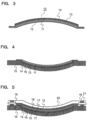
- FIG. 3 is a sectional view taken along the line III-III of FIG. 2 as viewed from the direction of the arrows.
- the outdoor cover 10 is manufactured by Vacuum Assisted Resin Transfer Molding (VaRTM), and includes a core 11 made of a foamed material having heat insulating property and closed cells, a surface member 12 made of a fiber reinforced plastic (FRP; hereinafter referred to as "FRP"), which covers the entire surfaces of the core 11 elastically deformed into a curved shape, a resin diffusion medium 13 interposed between an upper surface of the core 11 and the surface member 12, and a gel coat 14, which covers an upper surface of the surface member 12, all of which are integrated with each other.
- VaRTM Vacuum Assisted Resin Transfer Molding
- the FRP is obtained by impregnating carbon reinforcing fibers, which is excellent in lightness, mechanical properties, thermal properties, optical properties, and a degree of freedom of a molding method, with a vinyl ester resin as a base material resin.
- reinforcing fibers there may be used, for example, glass fibers, aramid fibers, Kevlar fibers, boron fibers, or alumina fibers.
- the base material resin there may be used, for example, a thermosetting resin such as an epoxy resin, an unsaturated polyester resin, a furan resin, or a polyurethane resin instead of the vinyl ester resin.
- a thermosetting resin such as an epoxy resin, an unsaturated polyester resin, a furan resin, or a polyurethane resin instead of the vinyl ester resin.
- the fibers may be, for example, staple fibers or filament fibers.
- the filament fibers are used from the viewpoint of mechanical properties, and textile fibers are used as a form of the fibers.
- the core 11 has a Young's modulus of from 9 MPa to 33 MPa and heat insulating property above the flame-retardance acceptance criteria defined in the Material Combustion Test for Vehicles of Rail (Article 83 of "Technical Regulatory Standards on Japanese Railways” (Ordinance No. 151 prescribed by the Ministry of Land, Infrastructure, Transport and Tourism, December 25, 2001) and is made of a foamed material including closed cells, which is a thermosetting resin. Specifically, the core 11 is made of a phenolic-resin foamed material.
- a thickness of the core 11 is set so that required heat insulating property and bending stiffness are obtained, and is suitably 3 to 30 mm, more preferably 9 mm.
- the thickness equal to or larger than 30 mm is not desired because a volume occupied by the outdoor cover 10 becomes larger. With the thickness equal to or smaller than 3 mm, the stiffness required as the outdoor cover 10 is not obtained.
- the Young's modulus of the core 11 there is adopted such a Young's modulus that deformation at an atmospheric pressure that the core undergoes in a manufacturing step described later is suppressed within an allowable range, and that the core 11 is deformed at a predetermined curvature.
- the deformation of the core 11 into the curved shape at the predetermined curvature is happening under its own weight at room temperature.
- a Young's modulus E is set within the range of a value obtained by the following formula using a curvature R of a predetermined shape, a length 1, a thickness t, a width b, a density ⁇ , an atmospheric pressure P, and a dimensional tolerance f.
- tP ⁇ ⁇ E ⁇ 5 ⁇ tl 4 32 t 3 R ⁇ R 2 ⁇ l 2 4
- FIG. 6 shows the results of a test for whether or not the core 11 with a thickness of 9 mm, which is placed in a molding die having a curvature of 1,800 mm and is deformed under its own weight, is actually deformed to lie along the molding die and the results of a test for whether or not a plate-thickness change occurring when the core 11 covered with a bagging film is subjected to vacuuming is within the fine-degree general dimensional tolerance of 0.1 mm, the results being marked with circles and crosses.
- the resin diffusion medium 13 includes a net-like flow channel formed therein.
- a vinyl ester resin which is a matrix resin, flows through the flow channel so that carbon reinforcing fibers are impregnated therewith.
- Carbon fibers are used as a material for the resin diffusion medium 13 from thermal and mechanical viewpoints.
- the material for the resin diffusion medium 13 may be, for example, glass fibers, aramid fibers, Kevlar fibers, boron fibers, alumina fibers, a thermosetting resin such as an epoxy resin, an unsaturated polyester resin, a vinyl ester resin, a furan resin, or a polyurethane resin, or a thermoplastic resin such as a nylon, a PBT, or a ABS.
- a thermosetting resin such as an epoxy resin, an unsaturated polyester resin, a vinyl ester resin, a furan resin, or a polyurethane resin
- a thermoplastic resin such as a nylon, a PBT, or a ABS.
- an unsaturated polyester resin which has flame retardance provided by bromination, is used from the viewpoint of the flame retardance so as to prevent the interior of the outdoor cover 10 from being adversely affected by light, water, heat, or the like.
- a material for the gel coat 14 may be, for example, a thermosetting resin such as an epoxy resin, a vinyl ester resin, a furan resin, or a polyurethane resin.
- a configuration of the indoor cover 9 is the same as that of the outdoor cover 10, and the description thereof is herein omitted.
- a gel coat resin is applied by using a spray gun to form the gel coat 14.
- a predetermined number of layers of textile fibers 16 are laminated in a predetermined direction on the gel coat 14.
- the resin diffusion medium 13 is laminated thereon.
- the resin diffusion medium 13 may be laminated between the textile fibers 16 and the gel coat 14 or between the textile fibers, the resin diffusion medium 13 is provided between the textile fibers 16 and the core 11 from the viewpoint of design.
- the core 11 is placed on the resin diffusion medium 13.
- the core 11 is deformed under its own weight so as to lie along the molding die 15 having the curvature of 1,800 mm, as illustrated in FIG. 4 .
- a predetermined number of layers of the textile fibers 16 are laminated in a predetermined direction.
- a peel ply 17 is laminated thereon. Then, the resin diffusion medium 13 is provided thereon.
- an intake port 18 for air to a vacuum pump and an injection port 19 for a resin to be injected from a resin tank (not shown) are mounted to the molding die 15.
- the entirety is covered with a bagging film 20.
- a periphery of the bagging film 20 is bonded to the molding die 15 with a sealant 21 so as to prevent air leakage.
- the interior including the textile fibers 16, which is covered with the bagging film 20 is placed into a vacuum state by using the vacuum pump. Then, a valve is released to inject the resin.
- the interior covered with the bagging film 20 is placed into the vacuum state.
- the resin passes through the two resin diffusion media 13 to be diffused in all the fibers while the textile fibers 16 are impregnated in a thickness direction (impregnation step).
- the valve is closed to cure the resin.
- the outdoor cover 10 for the air conditioning device for a railway vehicle in which the entire surfaces of the core 11 are covered with the surface member 12 made of the FRP, is demolded from the molding die 15.
- the indoor cover 9 is also manufactured by the same method as that for the outdoor cover 10.
- each of the covers 9 and 10 for the air conditioning device for a railway vehicle includes the core 11 made of the foamed material having the heat insulating property and the surface member 12 made of the FRP, in which the fibers are impregnated with the resin, for covering the entire surfaces of the core 11. Therefore, lightweight property is obtained, whereas an additional step of bonding a heat insulating material is not required. Thus, productivity is improved.
- the core 11 is deformed into the curved shape by the elastic deformation under its own weight. Therefore, as compared to a cover including a core, which is not elastically deformed, that is, a cover including a core, which is subjected to thermal deformation or deformation by cutting work or with a molding die in advance, the covers have a large repellant force with respect to the external force. Therefore, their withstand load increases.
- the core 11 is made of the foamed material and includes the closed cells, and hence the interior of the core 11 is not impregnated with the resin.
- a vacuum impregnation molding method can be employed for manufacturing the covers 9 and 10.
- the core 11 is made of the formed material including the closed cells, which has the Young's modulus of from 9 MPa to 33 MPa and the thickness of from 3 mm to 30 mm.
- An intermediate portion of the core 11 is flexurally deformed in a state in which the core 11 is supported at two points corresponding to both end portions before being covered with the surface member 12. Therefore, each of the covers 9 and 10 can realize the curved surface at the curvature of from 1,600 mm to 2,000 mm under its own weight. Thus, the thermal processing or cutting work is not required, thereby improving the productivity.
- the fibers are carbon fibers having high specific strength and specific stiffness.
- the covers 9 and 10 can be light-weighted.
- the surface member 12 and the core 11 are above the flame-retardance acceptance criteria in the Material Combustion Test for Vehicles of Rail.
- the flame retardance for railway vehicles can be ensured.
- the core 11 is made of a phenolic resin, which is a thermosetting resin. Therefore, the covers 9 and 10 excellent in mechanical properties and heat resistance can be obtained.
- the interior of the core 11 is not impregnated with the resin when the covers 9 and 10 are manufactured by the vacuum impregnation molding method.
- the core 11 is deformed to be curved under its own weight at room temperature.
- a thermal processing or cutting step is not required.
- the productivity of the covers 9 and 10 is improved.
- the formation of the curved shape is achieved without using a molding die having a curved shape, which costs high.
- low-cost production is achieved.
- covers for the air conditioning device for a railway vehicle and the method of manufacturing the same have been described in the embodiment described above, as a matter of course, the present invention is not limited thereto.
- the present invention may also be applied to, for example, covers for air conditioning devices for tramcars and buses.
Landscapes
- Engineering & Computer Science (AREA)
- Mechanical Engineering (AREA)
- Chemical & Material Sciences (AREA)
- Composite Materials (AREA)
- Physics & Mathematics (AREA)
- Thermal Sciences (AREA)
- Combustion & Propulsion (AREA)
- General Engineering & Computer Science (AREA)
- Casting Or Compression Moulding Of Plastics Or The Like (AREA)
- Laminated Bodies (AREA)
- Other Air-Conditioning Systems (AREA)
- Air-Conditioning For Vehicles (AREA)
Description
- The present invention relates to a cover for an air conditioning device for a vehicle, which is to be mounted, for example, on a ceiling portion of a railway vehicle, and to a method of manufacturing the same.
- Hitherto, as a cover for an air conditioning device for a vehicle, there is known a cover including an arch-like plate, reinforcing members provided on the outer side of the plate, and a heat insulating material provided on the inner side of the plate (see Patent Literature 1, for example).
- On the other hand, a fiber reinforced plastic (FRP) sandwich panel including a foamed material as a core is known to be capable of light-weighting while keeping stiffness and to have excellent heat insulating property (see Patent Literature 2, for example).
JP2009/241559 A -
- PTL 1
JP 06-072 326 A - PTL 2
JP 006-030 873 A - However, the cover described in Patent Literature 1 includes a plate, which is a stainless plate. Moreover, the reinforcing members are angle bars, and therefore a total weight is large. Moreover, the reinforcing members are required to be fixed by welding onto an upper surface of the plate, whereas the heat insulating material is required to be bonded onto a lower surface of the plate. Therefore, there is a problem of low productivity.
- In the case of an FRP sandwich panel described in Patent Literature 2, thermal processing or cutting work is required to be performed in advance on a core material in order to obtain a curved shape required for the cover for an air conditioning device for a vehicle. Therefore, productivity is low. Moreover, when a molding die is used, a die having a curved shape, which costs high, is required to be used. Thus, there is a problem in that costs run up.
- The present invention has been made to solve the problems described above, and has an object to provide a cover for an air conditioning device for a vehicle, which is capable of light-weighting and improving productivity at low costs, and a method of manufacturing the same.
- The invention is defined by the method of claim 1. According to one embodiment of the present disclosure, there is provided a cover for an air conditioning device for a vehicle, the cover including: a core made of a foamed material having heat insulating property; and a surface member for covering entire surfaces of the core, the surface member being made of a fiber reinforced plastic obtained by impregnating fibers with a resin, in which the core is elastically deformed into a curved shape.
- Further, according to one embodiment of the present disclosure, there is provided a method of manufacturing a cover for an air conditioning device for a vehicle, the method including the steps of:
- shaping the core including closed cells and the fibers by flexing an intermediate portion of the core to be elastically deformed in a state in which the core is supported at two points corresponding to both end portions of the core on a molding die having a curved shape;
- impregnating the fibers with the resin by injecting the resin into a sealed space formed between the molding die and the core by vacuuming; and
- demolding the cover from the molding die after the resin is cured.
- According to the cover for an air conditioning device for a vehicle of one embodiment of the present disclosure, the cover includes the core made of the foamed material having the heat insulating property and the surface member made of the fiber reinforced plastic, which covers the entire surfaces of the core. Therefore, lightweight property is obtained, whereas an additional step of bonding a heat insulating material is not required. Therefore, productivity is improved.
- Moreover, the core is elastically deformed into a curved shape. Therefore, as compared to a cover including a core, which is not elastically deformed, that is, a cover including a core, which is subjected to thermal deformation or deformation by cutting work or with a molding die in advance, a repelling force is large with respect to an external force. Thus, a withstand load increases.
- Moreover, according to the method of manufacturing the cover for an air conditioning device for a vehicle of one embodiment of the present invention, the core is elastically deformed into a curved shape under its own weight in the shaping step. Therefore, a step of deforming the core into the curved shape by thermal, cutting, or the molding die is not required. Therefore, the productivity is improved at low costs.
-
- FIG. 1
- is a plan view of an air conditioning device for a railway vehicle, onto which covers for an air conditioning device for a railway vehicle are mounted according to a first embodiment of the present disclosure.
- FIG. 2
- is a perspective view illustrating an outdoor cover illustrated in
FIG. 1 . - FIG. 3
- is a sectional view taken along the line III-III of
FIG. 2 , for illustrating the outdoor cover illustrated inFIG. 2 as viewed from the direction of the arrows. - FIG. 4
- is a sectional view illustrating a shaping step among steps of manufacturing the outdoor cover illustrated in
FIG. 2 by a vacuum impregnation molding method. - FIG. 5
- is a sectional view illustrating an impregnation step among the steps of manufacturing the outdoor cover illustrated in
FIG. 2 by the vacuum impregnation molding method. - FIG. 6
- is a table showing a relationship between a Young's modulus of a core and elastic deformation of the core under its own weight.
- Referring to the drawings, embodiments of the present invention are described below. In the drawings, the same or corresponding components and parts are denoted by the same reference symbols.
-
FIG. 1 is a plan view illustrating an air conditioning device for a railway vehicle, onto which covers 9 and 10 for an air conditioning device for a railway vehicle are mounted according to a first embodiment of the present disclosure. In the figure, right halves of thecovers 9 and 10 are cut out. - The air conditioning device for a railway vehicle is mounted onto a ceiling portion of the vehicle, and includes an indoor unit portion 1, which is in communication to a vehicle indoor side, an outdoor unit portion 2, a casing 3, which houses the indoor unit portion 1 and the outdoor unit portion 2 therein, and an indoor cover 9 for covering the indoor unit portion 1 and an
outdoor cover 10 for covering the outdoor unit portion 2, each being exposed to outside air. - Each of the indoor cover 9 and the
outdoor cover 10 is, as illustrated inFIG. 2 , rectangular, and has a curved shape with a curved surface projecting upward at a curvature of from 1,500 mm to 2,500 mm, the curvature being suitably 1,800 mm in order to maximally using a space from the viewpoint of a vehicle gauge. - The indoor cover 9 and the
outdoor cover 10 cover an air-conditioner main body, which includes the indoor unit portion 1 and the outdoor unit portion 2. - The indoor unit portion 1 includes an indoor fan 4 and an
indoor heat exchanger 5. - The outdoor unit portion 2 includes an
outdoor fan 6, anoutdoor heat exchanger 7, and acompressor 8. -
FIG. 3 is a sectional view taken along the line III-III ofFIG. 2 as viewed from the direction of the arrows. - The
outdoor cover 10 is manufactured by Vacuum Assisted Resin Transfer Molding (VaRTM), and includes acore 11 made of a foamed material having heat insulating property and closed cells, asurface member 12 made of a fiber reinforced plastic (FRP; hereinafter referred to as "FRP"), which covers the entire surfaces of thecore 11 elastically deformed into a curved shape, aresin diffusion medium 13 interposed between an upper surface of thecore 11 and thesurface member 12, and agel coat 14, which covers an upper surface of thesurface member 12, all of which are integrated with each other. - The FRP is obtained by impregnating carbon reinforcing fibers, which is excellent in lightness, mechanical properties, thermal properties, optical properties, and a degree of freedom of a molding method, with a vinyl ester resin as a base material resin.
- Note that, as reinforcing fibers, there may be used, for example, glass fibers, aramid fibers, Kevlar fibers, boron fibers, or alumina fibers.
- In addition, as the base material resin, there may be used, for example, a thermosetting resin such as an epoxy resin, an unsaturated polyester resin, a furan resin, or a polyurethane resin instead of the vinyl ester resin.
- The fibers may be, for example, staple fibers or filament fibers. The filament fibers are used from the viewpoint of mechanical properties, and textile fibers are used as a form of the fibers.
- The
core 11 has a Young's modulus of from 9 MPa to 33 MPa and heat insulating property above the flame-retardance acceptance criteria defined in the Material Combustion Test for Vehicles of Railroad (Article 83 of "Technical Regulatory Standards on Japanese Railways" (Ordinance No. 151 prescribed by the Ministry of Land, Infrastructure, Transport and Tourism, December 25, 2001) and is made of a foamed material including closed cells, which is a thermosetting resin. Specifically, thecore 11 is made of a phenolic-resin foamed material. - A thickness of the
core 11 is set so that required heat insulating property and bending stiffness are obtained, and is suitably 3 to 30 mm, more preferably 9 mm. The thickness equal to or larger than 30 mm is not desired because a volume occupied by theoutdoor cover 10 becomes larger. With the thickness equal to or smaller than 3 mm, the stiffness required as theoutdoor cover 10 is not obtained. - As the Young's modulus of the core 11, there is adopted such a Young's modulus that deformation at an atmospheric pressure that the core undergoes in a manufacturing step described later is suppressed within an allowable range, and that the
core 11 is deformed at a predetermined curvature. - The deformation of the core 11 into the curved shape at the predetermined curvature is happening under its own weight at room temperature.
- Specifically, a Young's modulus E is set within the range of a value obtained by the following formula using a curvature R of a predetermined shape, a length 1, a thickness t, a width b, a density ρ, an atmospheric pressure P, and a dimensional tolerance f.
[Math. 1]
- Formula (1) is derived based on the fact that a deflection amount obtained from Formula (2):
[Math. 2]
- for a maximum deflection amount δmax of a two-point support beam having a rectangular cross section, which is subjected to its own weight, exceeds a maximum depth D,
[Math. 3]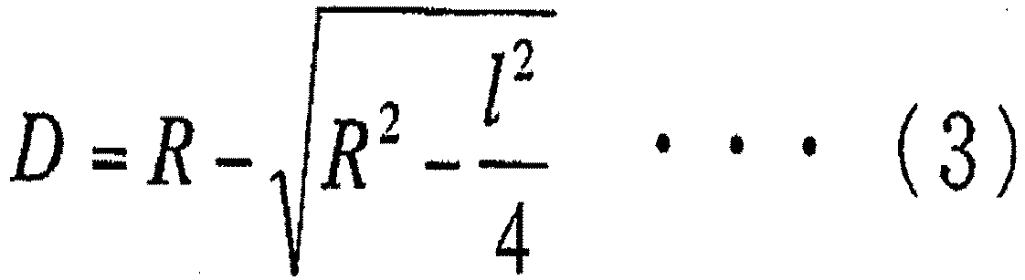
- of a curved surface having the curvature R and the length 1 and that a change in plate thickness under the atmospheric pressure P:
[Math. 4]
- falls within an allowable deformation amount f.
- By substituting t = 9 mm, f = 0.1 mm (fine-degree general dimensional tolerance), R = 1,800 mm, 1 = 1,800 mm, ρ = 0.00000004 kg/mm3 into Formula (1) as the most preferred conditions, the best mode can be realized with the Young's modulus E of from 9 MPa to 33 MPa.
-
FIG. 6 shows the results of a test for whether or not the core 11 with a thickness of 9 mm, which is placed in a molding die having a curvature of 1,800 mm and is deformed under its own weight, is actually deformed to lie along the molding die and the results of a test for whether or not a plate-thickness change occurring when the core 11 covered with a bagging film is subjected to vacuuming is within the fine-degree general dimensional tolerance of 0.1 mm, the results being marked with circles and crosses. - From the above-mentioned results, it is verified that the core 11 having the Young's modulus E of from 9 MPa to 33 MPa is deformed to lie along the curvature of 1,800 mm under its own weight without undergoing a thermal processing or cutting work step and that the deformation at the atmospheric pressure can be suppressed within the fine-degree general dimensional tolerance.
- The
resin diffusion medium 13 includes a net-like flow channel formed therein. A vinyl ester resin, which is a matrix resin, flows through the flow channel so that carbon reinforcing fibers are impregnated therewith. - Carbon fibers are used as a material for the
resin diffusion medium 13 from thermal and mechanical viewpoints. - Note that, the material for the
resin diffusion medium 13 may be, for example, glass fibers, aramid fibers, Kevlar fibers, boron fibers, alumina fibers, a thermosetting resin such as an epoxy resin, an unsaturated polyester resin, a vinyl ester resin, a furan resin, or a polyurethane resin, or a thermoplastic resin such as a nylon, a PBT, or a ABS. - As the
gel coat 14, an unsaturated polyester resin, which has flame retardance provided by bromination, is used from the viewpoint of the flame retardance so as to prevent the interior of theoutdoor cover 10 from being adversely affected by light, water, heat, or the like. - Note that, a material for the
gel coat 14 may be, for example, a thermosetting resin such as an epoxy resin, a vinyl ester resin, a furan resin, or a polyurethane resin. - Note that, a configuration of the indoor cover 9 is the same as that of the
outdoor cover 10, and the description thereof is herein omitted. - Next, a method of manufacturing the
outdoor cover 10 for the air conditioning device for a railway vehicle according to the first embodiment of the present invention is described. - First, onto a
molding die 15, which is subjected to demolding processing with a Teflon (trademark) coating, a gel coat resin is applied by using a spray gun to form thegel coat 14. - Next, a predetermined number of layers of
textile fibers 16 are laminated in a predetermined direction on thegel coat 14. - Thereafter, the
resin diffusion medium 13 is laminated thereon. Although theresin diffusion medium 13 may be laminated between thetextile fibers 16 and thegel coat 14 or between the textile fibers, theresin diffusion medium 13 is provided between thetextile fibers 16 and the core 11 from the viewpoint of design. - Next, the
core 11 is placed on theresin diffusion medium 13. - In this manner, in a shaping step in which the
textile fibers 16, theresin diffusion medium 13, and the core 11 are shaped sequentially on the molding die 15, thecore 11 is deformed under its own weight so as to lie along the molding die 15 having the curvature of 1,800 mm, as illustrated inFIG. 4 . - Next, as illustrated in
FIG. 5 , a predetermined number of layers of thetextile fibers 16 are laminated in a predetermined direction. - A peel ply 17 is laminated thereon. Then, the
resin diffusion medium 13 is provided thereon. - Next, an
intake port 18 for air to a vacuum pump and aninjection port 19 for a resin to be injected from a resin tank (not shown) are mounted to the molding die 15. The entirety is covered with abagging film 20. A periphery of thebagging film 20 is bonded to the molding die 15 with asealant 21 so as to prevent air leakage. - Thereafter, the interior including the
textile fibers 16, which is covered with the baggingfilm 20, is placed into a vacuum state by using the vacuum pump. Then, a valve is released to inject the resin. - The interior covered with the bagging
film 20 is placed into the vacuum state. The resin passes through the tworesin diffusion media 13 to be diffused in all the fibers while thetextile fibers 16 are impregnated in a thickness direction (impregnation step). - After the impregnation step, the valve is closed to cure the resin.
- After the resin is cured, the bagging
film 20, one of theresin diffusion media 13, which is located on the upper side, and the peel ply 17 are removed. Finally, theoutdoor cover 10 for the air conditioning device for a railway vehicle, in which the entire surfaces of the core 11 are covered with thesurface member 12 made of the FRP, is demolded from the molding die 15. - Note that, the indoor cover 9 is also manufactured by the same method as that for the
outdoor cover 10. - As described above, each of the
covers 9 and 10 for the air conditioning device for a railway vehicle according to this embodiment includes the core 11 made of the foamed material having the heat insulating property and thesurface member 12 made of the FRP, in which the fibers are impregnated with the resin, for covering the entire surfaces of thecore 11. Therefore, lightweight property is obtained, whereas an additional step of bonding a heat insulating material is not required. Thus, productivity is improved. - Moreover, the
core 11 is deformed into the curved shape by the elastic deformation under its own weight. Therefore, as compared to a cover including a core, which is not elastically deformed, that is, a cover including a core, which is subjected to thermal deformation or deformation by cutting work or with a molding die in advance, the covers have a large repellant force with respect to the external force. Therefore, their withstand load increases. - Moreover, the
core 11 is made of the foamed material and includes the closed cells, and hence the interior of thecore 11 is not impregnated with the resin. Thus, for manufacturing thecovers 9 and 10, a vacuum impregnation molding method can be employed. - Moreover, the
core 11 is made of the formed material including the closed cells, which has the Young's modulus of from 9 MPa to 33 MPa and the thickness of from 3 mm to 30 mm. An intermediate portion of thecore 11 is flexurally deformed in a state in which thecore 11 is supported at two points corresponding to both end portions before being covered with thesurface member 12. Therefore, each of thecovers 9 and 10 can realize the curved surface at the curvature of from 1,600 mm to 2,000 mm under its own weight. Thus, the thermal processing or cutting work is not required, thereby improving the productivity. - Moreover, the fibers are carbon fibers having high specific strength and specific stiffness. Thus, the
covers 9 and 10 can be light-weighted. - Moreover, the
surface member 12 and the core 11 are above the flame-retardance acceptance criteria in the Material Combustion Test for Vehicles of Railroad. Thus, for thecovers 9 and 10, the flame retardance for railway vehicles can be ensured. - Moreover, the
core 11 is made of a phenolic resin, which is a thermosetting resin. Therefore, thecovers 9 and 10 excellent in mechanical properties and heat resistance can be obtained. - Further, according to the method of manufacturing the
covers 9 and 10 for the air conditioning device for a vehicle according to this embodiment, for the core 11 made of the foamed material including the closed cells, the interior of thecore 11 is not impregnated with the resin when thecovers 9 and 10 are manufactured by the vacuum impregnation molding method. - Moreover, in the shaping step of shaping the core 11 on the molding die 15, the
core 11 is deformed to be curved under its own weight at room temperature. Thus, for the deformation of the core 11, a thermal processing or cutting step is not required. As a result, the productivity of thecovers 9 and 10 is improved. Moreover, the formation of the curved shape is achieved without using a molding die having a curved shape, which costs high. Thus, low-cost production is achieved. - Note that, although the covers for the air conditioning device for a railway vehicle and the method of manufacturing the same have been described in the embodiment described above, as a matter of course, the present invention is not limited thereto. The present invention may also be applied to, for example, covers for air conditioning devices for tramcars and buses.
-
- 1
- indoor unit portion,
- 2
- outdoor unit portion,
- 3
- casing,
- 4
- indoor fan,
- 5
- indoor heat exchanger,
- 6
- outdoor fan,
- 7
- outdoor heat exchanger,
- 8
- compressor,
- 9
- indoor cover,
- 10
- outdoor cover,
- 11
- core,
- 12
- surface member,
- 13
- resin diffusion medium,
- 14
- gel coat,
- 15
- molding die,
- 16
- textile fibers,
- 17
- peel ply,
- 18
- intake port,
- 19
- injection port,
- 20
- bagging film,
- 21
- sealant.
Claims (3)
- A method of manufacturing a cover for an air conditioning device for a vehicle, which is configured to cover an air-conditioner main body mounted on a ceiling portion of the vehicle, the cover comprising:- - a core (11) made of a foamed material having heat insulating property; and- - a surface member (12) for covering entire surfaces of the core (11), the surface member (12) being made of a fiber reinforced plastic obtained by impregnating fibers with a resin,
the method comprising the steps of:- - shaping the core (11) comprising closed cells and the fibers by flexing an intermediate portion of the core (11) to be elastically deformed in a state in which the core (11) is supported at two points corresponding to both end portions of the core (11) on a molding die (15) having a curved shape;- - impregnating the fibers with the resin by injecting the resin into a sealed space formed between the molding die (15) and the core (11) by vacuuming; and- - demolding the cover from the molding die (15) after the resin is cured, wherein the shaping comprises elastically deforming the core (11) under own weight at room temperature. - The method according to claim 1,wherein the core (11) has a Young's modulus E calculated by the following Formula with a curvature R, a length 1, a thickness t, a density ρ, an atmospheric pressure P, and a general dimensional tolerance f:
 and wherein the core (11) has the Young's modulus of from 9 to 33 MPa.
 - The method according to any one of claims 1 and 2,
wherein the core (11) is made of a thermosetting resin.
Applications Claiming Priority (2)
| Application Number | Priority Date | Filing Date | Title |
|---|---|---|---|
| JP2012110362 | 2012-05-14 | ||
| PCT/JP2013/063422 WO2013172345A1 (en) | 2012-05-14 | 2013-05-14 | Cover for air conditioning device for vehicle, and method for manufacturing same |
Publications (3)
| Publication Number | Publication Date |
|---|---|
| EP2851259A1 EP2851259A1 (en) | 2015-03-25 |
| EP2851259A4 EP2851259A4 (en) | 2016-02-10 |
| EP2851259B1 true EP2851259B1 (en) | 2024-09-25 |
Family
ID=49583750
Family Applications (1)
| Application Number | Title | Priority Date | Filing Date |
|---|---|---|---|
| EP13791701.9A Active EP2851259B1 (en) | 2012-05-14 | 2013-05-14 | Method for manufacturing a cover for air conditioning device for vehicle |
Country Status (4)
| Country | Link |
|---|---|
| US (1) | US9643365B2 (en) |
| EP (1) | EP2851259B1 (en) |
| JP (1) | JP5748909B2 (en) |
| WO (1) | WO2013172345A1 (en) |
Families Citing this family (4)
| Publication number | Priority date | Publication date | Assignee | Title |
|---|---|---|---|---|
| JP5850032B2 (en) * | 2013-11-26 | 2016-02-03 | ダイキン工業株式会社 | Indoor unit |
| JP6504993B2 (en) * | 2014-11-28 | 2019-04-24 | 三菱電機株式会社 | Method of manufacturing curved sandwich structure |
| CN116147182A (en) * | 2021-11-19 | 2023-05-23 | 青岛海尔空调器有限总公司 | Design method, device and storage medium for wind deflector |
| DE102023201910A1 (en) | 2023-03-02 | 2024-09-05 | Siemens Mobility GmbH | Arrangement of a thermal compartment in a room of a rail vehicle |
Family Cites Families (15)
| Publication number | Priority date | Publication date | Assignee | Title |
|---|---|---|---|---|
| JPS4974266A (en) * | 1972-11-18 | 1974-07-17 | ||
| JPH03262635A (en) * | 1990-03-13 | 1991-11-22 | Sekisui Plastics Co Ltd | Manufacture of curved surface panel |
| JPH0343017A (en) | 1990-03-23 | 1991-02-25 | Iseki & Co Ltd | combine |
| JPH0672326A (en) * | 1992-08-31 | 1994-03-15 | Toshiba Corp | Vehicle air conditioner |
| JP3136869B2 (en) | 1993-11-04 | 2001-02-19 | 東レ株式会社 | Sandwich structural materials |
| JP3837226B2 (en) | 1998-02-05 | 2006-10-25 | 旭化成建材株式会社 | Phenol resin foam laminate and method for producing the same |
| JP3099879B2 (en) * | 1998-08-06 | 2000-10-16 | 木村工機株式会社 | Sandwich panel for air conditioner |
| JP2000264199A (en) * | 1999-05-14 | 2000-09-26 | Kawasaki Heavy Ind Ltd | Railcar structure |
| US6918985B2 (en) * | 2002-12-12 | 2005-07-19 | The Boeing Company | Method for making a radome |
| JP4494168B2 (en) * | 2004-11-09 | 2010-06-30 | ユニバーサル造船株式会社 | FRP sandwich molding and manufacturing method thereof |
| JP4624156B2 (en) * | 2005-03-29 | 2011-02-02 | 三菱電機株式会社 | Exterior duct structure of vehicle air conditioner |
| JP2008055628A (en) * | 2006-08-29 | 2008-03-13 | Nippon Sheet Glass Co Ltd | Thermal deformation method of thermoplastic resin plate |
| JP2009241559A (en) * | 2008-03-31 | 2009-10-22 | Mitsui Eng & Shipbuild Co Ltd | Laminated panel and method for manufacturing the same |
| JP5436314B2 (en) * | 2010-04-09 | 2014-03-05 | 三菱電機株式会社 | Curved sandwich panel |
| JP6126574B2 (en) * | 2012-02-23 | 2017-05-10 | 川崎重工業株式会社 | Railway vehicle with low roof structure |
-
2013
- 2013-05-14 US US14/390,823 patent/US9643365B2/en active Active
- 2013-05-14 WO PCT/JP2013/063422 patent/WO2013172345A1/en not_active Ceased
- 2013-05-14 JP JP2014515637A patent/JP5748909B2/en active Active
- 2013-05-14 EP EP13791701.9A patent/EP2851259B1/en active Active
Also Published As
| Publication number | Publication date |
|---|---|
| US9643365B2 (en) | 2017-05-09 |
| JPWO2013172345A1 (en) | 2016-01-12 |
| WO2013172345A1 (en) | 2013-11-21 |
| EP2851259A1 (en) | 2015-03-25 |
| JP5748909B2 (en) | 2015-07-15 |
| US20150084242A1 (en) | 2015-03-26 |
| EP2851259A4 (en) | 2016-02-10 |
Similar Documents
| Publication | Publication Date | Title |
|---|---|---|
| EP1555104B1 (en) | Method of frp molding | |
| US7645120B2 (en) | Flow-guiding member unit and its production method | |
| JP6273804B2 (en) | Manufacturing method of fiber reinforced plastic molding | |
| JP4639551B2 (en) | Method for producing CFRP skin-stringer structural member | |
| US20130252059A1 (en) | Battery pack case assembly for electric and hybrid vehicles using a plastic composite and method for manufacturing the same | |
| US9643365B2 (en) | Cover for air conditioning device for vehicle, and method for manufacturing same | |
| CA2628261A1 (en) | Single piece fuselage barrel | |
| US10232569B2 (en) | Device and method for manufacturing fiber-reinforced plastic structure | |
| KR20190111950A (en) | Preform elements, and preforms using the same and methods for producing the same | |
| CA3040845C (en) | Fan rotor blade and method of manufacturing same | |
| CN110997268A (en) | Manufacturing method of composite material and composite material | |
| EP1595688B1 (en) | Molded laminate and manufacturing method thereof | |
| JP2013538728A (en) | Thermoplastic fuel tank | |
| US20140361467A1 (en) | Method and device for molding fiber-reinforced plastic member | |
| JP2944967B2 (en) | High-speed vehicle outer wall structure and high-speed vehicle outer wall manufacturing method | |
| KR102860780B1 (en) | Preform forming method and composite shaping method | |
| US10611328B2 (en) | Composite material structural member and method of manufacturing the composite material structural member | |
| US10603869B2 (en) | Laminated structure and method for manufacturing the same | |
| CA2987171C (en) | Honeycomb core sandwich panels | |
| KR102466802B1 (en) | Forming Method Of Composite Material And Product Using The Same | |
| JP4761178B2 (en) | Method for manufacturing FRP large planar body | |
| JP4941811B2 (en) | Manufacturing method of preform and FRP molded body | |
| CN110299598A (en) | A kind of aramid fiber covering-paper honeycomb interlayer barrel shell structure and its preparation method and application | |
| JP5238152B2 (en) | Laminate and automobile bonnet using the same | |
| KR20220109614A (en) | Vehicle wheel using fiber reinforced composite material and manufacturing method thereof |
Legal Events
| Date | Code | Title | Description |
|---|---|---|---|
| PUAI | Public reference made under article 153(3) epc to a published international application that has entered the european phase |
Free format text: ORIGINAL CODE: 0009012 |
|
| 17P | Request for examination filed |
Effective date: 20141106 |
|
| AK | Designated contracting states |
Kind code of ref document: A1 Designated state(s): AL AT BE BG CH CY CZ DE DK EE ES FI FR GB GR HR HU IE IS IT LI LT LU LV MC MK MT NL NO PL PT RO RS SE SI SK SM TR |
|
| AX | Request for extension of the european patent |
Extension state: BA ME |
|
| DAX | Request for extension of the european patent (deleted) | ||
| RA4 | Supplementary search report drawn up and despatched (corrected) |
Effective date: 20160112 |
|
| RIC1 | Information provided on ipc code assigned before grant |
Ipc: B60H 1/32 20060101ALI20160106BHEP Ipc: B61D 27/00 20060101AFI20160106BHEP Ipc: B29C 43/12 20060101ALI20160106BHEP Ipc: B60H 1/00 20060101ALI20160106BHEP Ipc: B32B 5/24 20060101ALI20160106BHEP Ipc: B29C 43/18 20060101ALI20160106BHEP |
|
| STAA | Information on the status of an ep patent application or granted ep patent |
Free format text: STATUS: EXAMINATION IS IN PROGRESS |
|
| 17Q | First examination report despatched |
Effective date: 20180215 |
|
| RIC1 | Information provided on ipc code assigned before grant |
Ipc: B32B 1/00 20060101ALI20220804BHEP Ipc: B29C 70/86 20060101ALI20220804BHEP Ipc: B29C 70/44 20060101ALI20220804BHEP Ipc: B29C 39/10 20060101ALI20220804BHEP Ipc: B60H 1/32 20060101ALI20220804BHEP Ipc: B60H 1/00 20060101ALI20220804BHEP Ipc: B32B 5/24 20060101ALI20220804BHEP Ipc: B29C 43/18 20060101ALI20220804BHEP Ipc: B29C 43/12 20060101ALI20220804BHEP Ipc: B61D 27/00 20060101AFI20220804BHEP |
|
| GRAP | Despatch of communication of intention to grant a patent |
Free format text: ORIGINAL CODE: EPIDOSNIGR1 |
|
| STAA | Information on the status of an ep patent application or granted ep patent |
Free format text: STATUS: GRANT OF PATENT IS INTENDED |
|
| INTG | Intention to grant announced |
Effective date: 20240607 |
|
| GRAS | Grant fee paid |
Free format text: ORIGINAL CODE: EPIDOSNIGR3 |
|
| GRAA | (expected) grant |
Free format text: ORIGINAL CODE: 0009210 |
|
| STAA | Information on the status of an ep patent application or granted ep patent |
Free format text: STATUS: THE PATENT HAS BEEN GRANTED |
|
| AK | Designated contracting states |
Kind code of ref document: B1 Designated state(s): AL AT BE BG CH CY CZ DE DK EE ES FI FR GB GR HR HU IE IS IT LI LT LU LV MC MK MT NL NO PL PT RO RS SE SI SK SM TR |
|
| REG | Reference to a national code |
Ref country code: GB Ref legal event code: FG4D |
|
| REG | Reference to a national code |
Ref country code: CH Ref legal event code: EP |
|
| REG | Reference to a national code |
Ref country code: DE Ref legal event code: R096 Ref document number: 602013086119 Country of ref document: DE |
|
| REG | Reference to a national code |
Ref country code: IE Ref legal event code: FG4D |
|
| REG | Reference to a national code |
Ref country code: LT Ref legal event code: MG9D |
|
| PG25 | Lapsed in a contracting state [announced via postgrant information from national office to epo] |
Ref country code: NO Free format text: LAPSE BECAUSE OF FAILURE TO SUBMIT A TRANSLATION OF THE DESCRIPTION OR TO PAY THE FEE WITHIN THE PRESCRIBED TIME-LIMIT Effective date: 20241225 |
|
| PG25 | Lapsed in a contracting state [announced via postgrant information from national office to epo] |
Ref country code: GR Free format text: LAPSE BECAUSE OF FAILURE TO SUBMIT A TRANSLATION OF THE DESCRIPTION OR TO PAY THE FEE WITHIN THE PRESCRIBED TIME-LIMIT Effective date: 20241226 Ref country code: FI Free format text: LAPSE BECAUSE OF FAILURE TO SUBMIT A TRANSLATION OF THE DESCRIPTION OR TO PAY THE FEE WITHIN THE PRESCRIBED TIME-LIMIT Effective date: 20240925 |
|
| PG25 | Lapsed in a contracting state [announced via postgrant information from national office to epo] |
Ref country code: BG Free format text: LAPSE BECAUSE OF FAILURE TO SUBMIT A TRANSLATION OF THE DESCRIPTION OR TO PAY THE FEE WITHIN THE PRESCRIBED TIME-LIMIT Effective date: 20240925 |
|
| PG25 | Lapsed in a contracting state [announced via postgrant information from national office to epo] |
Ref country code: LV Free format text: LAPSE BECAUSE OF FAILURE TO SUBMIT A TRANSLATION OF THE DESCRIPTION OR TO PAY THE FEE WITHIN THE PRESCRIBED TIME-LIMIT Effective date: 20240925 |
|
| PG25 | Lapsed in a contracting state [announced via postgrant information from national office to epo] |
Ref country code: RS Free format text: LAPSE BECAUSE OF FAILURE TO SUBMIT A TRANSLATION OF THE DESCRIPTION OR TO PAY THE FEE WITHIN THE PRESCRIBED TIME-LIMIT Effective date: 20241225 |
|
| REG | Reference to a national code |
Ref country code: NL Ref legal event code: MP Effective date: 20240925 |
|
| PG25 | Lapsed in a contracting state [announced via postgrant information from national office to epo] |
Ref country code: RS Free format text: LAPSE BECAUSE OF FAILURE TO SUBMIT A TRANSLATION OF THE DESCRIPTION OR TO PAY THE FEE WITHIN THE PRESCRIBED TIME-LIMIT Effective date: 20241225 Ref country code: NO Free format text: LAPSE BECAUSE OF FAILURE TO SUBMIT A TRANSLATION OF THE DESCRIPTION OR TO PAY THE FEE WITHIN THE PRESCRIBED TIME-LIMIT Effective date: 20241225 Ref country code: LV Free format text: LAPSE BECAUSE OF FAILURE TO SUBMIT A TRANSLATION OF THE DESCRIPTION OR TO PAY THE FEE WITHIN THE PRESCRIBED TIME-LIMIT Effective date: 20240925 Ref country code: GR Free format text: LAPSE BECAUSE OF FAILURE TO SUBMIT A TRANSLATION OF THE DESCRIPTION OR TO PAY THE FEE WITHIN THE PRESCRIBED TIME-LIMIT Effective date: 20241226 Ref country code: FI Free format text: LAPSE BECAUSE OF FAILURE TO SUBMIT A TRANSLATION OF THE DESCRIPTION OR TO PAY THE FEE WITHIN THE PRESCRIBED TIME-LIMIT Effective date: 20240925 Ref country code: BG Free format text: LAPSE BECAUSE OF FAILURE TO SUBMIT A TRANSLATION OF THE DESCRIPTION OR TO PAY THE FEE WITHIN THE PRESCRIBED TIME-LIMIT Effective date: 20240925 |
|
| REG | Reference to a national code |
Ref country code: AT Ref legal event code: MK05 Ref document number: 1726448 Country of ref document: AT Kind code of ref document: T Effective date: 20240925 |
|
| PG25 | Lapsed in a contracting state [announced via postgrant information from national office to epo] |
Ref country code: NL Free format text: LAPSE BECAUSE OF FAILURE TO SUBMIT A TRANSLATION OF THE DESCRIPTION OR TO PAY THE FEE WITHIN THE PRESCRIBED TIME-LIMIT Effective date: 20240925 |
|
| PG25 | Lapsed in a contracting state [announced via postgrant information from national office to epo] |
Ref country code: IS Free format text: LAPSE BECAUSE OF FAILURE TO SUBMIT A TRANSLATION OF THE DESCRIPTION OR TO PAY THE FEE WITHIN THE PRESCRIBED TIME-LIMIT Effective date: 20250125 Ref country code: PT Free format text: LAPSE BECAUSE OF FAILURE TO SUBMIT A TRANSLATION OF THE DESCRIPTION OR TO PAY THE FEE WITHIN THE PRESCRIBED TIME-LIMIT Effective date: 20250127 |
|
| PG25 | Lapsed in a contracting state [announced via postgrant information from national office to epo] |
Ref country code: RO Free format text: LAPSE BECAUSE OF FAILURE TO SUBMIT A TRANSLATION OF THE DESCRIPTION OR TO PAY THE FEE WITHIN THE PRESCRIBED TIME-LIMIT Effective date: 20240925 Ref country code: SM Free format text: LAPSE BECAUSE OF FAILURE TO SUBMIT A TRANSLATION OF THE DESCRIPTION OR TO PAY THE FEE WITHIN THE PRESCRIBED TIME-LIMIT Effective date: 20240925 |
|
| PG25 | Lapsed in a contracting state [announced via postgrant information from national office to epo] |
Ref country code: ES Free format text: LAPSE BECAUSE OF FAILURE TO SUBMIT A TRANSLATION OF THE DESCRIPTION OR TO PAY THE FEE WITHIN THE PRESCRIBED TIME-LIMIT Effective date: 20240925 |
|
| PG25 | Lapsed in a contracting state [announced via postgrant information from national office to epo] |
Ref country code: EE Free format text: LAPSE BECAUSE OF FAILURE TO SUBMIT A TRANSLATION OF THE DESCRIPTION OR TO PAY THE FEE WITHIN THE PRESCRIBED TIME-LIMIT Effective date: 20240925 Ref country code: AT Free format text: LAPSE BECAUSE OF FAILURE TO SUBMIT A TRANSLATION OF THE DESCRIPTION OR TO PAY THE FEE WITHIN THE PRESCRIBED TIME-LIMIT Effective date: 20240925 |
|
| PG25 | Lapsed in a contracting state [announced via postgrant information from national office to epo] |
Ref country code: CZ Free format text: LAPSE BECAUSE OF FAILURE TO SUBMIT A TRANSLATION OF THE DESCRIPTION OR TO PAY THE FEE WITHIN THE PRESCRIBED TIME-LIMIT Effective date: 20240925 Ref country code: PL Free format text: LAPSE BECAUSE OF FAILURE TO SUBMIT A TRANSLATION OF THE DESCRIPTION OR TO PAY THE FEE WITHIN THE PRESCRIBED TIME-LIMIT Effective date: 20240925 |
|
| PG25 | Lapsed in a contracting state [announced via postgrant information from national office to epo] |
Ref country code: SK Free format text: LAPSE BECAUSE OF FAILURE TO SUBMIT A TRANSLATION OF THE DESCRIPTION OR TO PAY THE FEE WITHIN THE PRESCRIBED TIME-LIMIT Effective date: 20240925 |
|
| REG | Reference to a national code |
Ref country code: DE Ref legal event code: R097 Ref document number: 602013086119 Country of ref document: DE |
|
| PGFP | Annual fee paid to national office [announced via postgrant information from national office to epo] |
Ref country code: DE Payment date: 20250402 Year of fee payment: 13 |
|
| PG25 | Lapsed in a contracting state [announced via postgrant information from national office to epo] |
Ref country code: DK Free format text: LAPSE BECAUSE OF FAILURE TO SUBMIT A TRANSLATION OF THE DESCRIPTION OR TO PAY THE FEE WITHIN THE PRESCRIBED TIME-LIMIT Effective date: 20240925 |
|
| PGFP | Annual fee paid to national office [announced via postgrant information from national office to epo] |
Ref country code: IT Payment date: 20250422 Year of fee payment: 13 |
|
| PGFP | Annual fee paid to national office [announced via postgrant information from national office to epo] |
Ref country code: FR Payment date: 20250401 Year of fee payment: 13 |
|
| PLBE | No opposition filed within time limit |
Free format text: ORIGINAL CODE: 0009261 |
|
| STAA | Information on the status of an ep patent application or granted ep patent |
Free format text: STATUS: NO OPPOSITION FILED WITHIN TIME LIMIT |
|
| 26N | No opposition filed |
Effective date: 20250626 |
|
| PG25 | Lapsed in a contracting state [announced via postgrant information from national office to epo] |
Ref country code: SE Free format text: LAPSE BECAUSE OF FAILURE TO SUBMIT A TRANSLATION OF THE DESCRIPTION OR TO PAY THE FEE WITHIN THE PRESCRIBED TIME-LIMIT Effective date: 20240925 |
|
| P01 | Opt-out of the competence of the unified patent court (upc) registered |
Free format text: CASE NUMBER: UPC_APP_4857_2851259/2025 Effective date: 20250827 |
|
| REG | Reference to a national code |
Ref country code: CH Ref legal event code: H13 Free format text: ST27 STATUS EVENT CODE: U-0-0-H10-H13 (AS PROVIDED BY THE NATIONAL OFFICE) Effective date: 20251223 |
|
| PG25 | Lapsed in a contracting state [announced via postgrant information from national office to epo] |
Ref country code: HR Free format text: LAPSE BECAUSE OF FAILURE TO SUBMIT A TRANSLATION OF THE DESCRIPTION OR TO PAY THE FEE WITHIN THE PRESCRIBED TIME-LIMIT Effective date: 20240925 Ref country code: LU Free format text: LAPSE BECAUSE OF NON-PAYMENT OF DUE FEES Effective date: 20250514 |
|
| PG25 | Lapsed in a contracting state [announced via postgrant information from national office to epo] |
Ref country code: CH Free format text: LAPSE BECAUSE OF NON-PAYMENT OF DUE FEES Effective date: 20250531 |
|
| REG | Reference to a national code |
Ref country code: BE Ref legal event code: MM Effective date: 20250531 |
|
| PG25 | Lapsed in a contracting state [announced via postgrant information from national office to epo] |
Ref country code: MC Free format text: LAPSE BECAUSE OF FAILURE TO SUBMIT A TRANSLATION OF THE DESCRIPTION OR TO PAY THE FEE WITHIN THE PRESCRIBED TIME-LIMIT Effective date: 20240925 |
|
| PGFP | Annual fee paid to national office [announced via postgrant information from national office to epo] |
Ref country code: GB Payment date: 20260323 Year of fee payment: 14 |
|
| PG25 | Lapsed in a contracting state [announced via postgrant information from national office to epo] |
Ref country code: IE Free format text: LAPSE BECAUSE OF NON-PAYMENT OF DUE FEES Effective date: 20250514 |
|
| PG25 | Lapsed in a contracting state [announced via postgrant information from national office to epo] |
Ref country code: BE Free format text: LAPSE BECAUSE OF NON-PAYMENT OF DUE FEES Effective date: 20250531 |