EP2851241B1 - Method for safely managing flammable substances - Google Patents
Method for safely managing flammable substances Download PDFInfo
- Publication number
- EP2851241B1 EP2851241B1 EP14185528.8A EP14185528A EP2851241B1 EP 2851241 B1 EP2851241 B1 EP 2851241B1 EP 14185528 A EP14185528 A EP 14185528A EP 2851241 B1 EP2851241 B1 EP 2851241B1
- Authority
- EP
- European Patent Office
- Prior art keywords
- tank
- volume
- ventilated
- purging
- pumping circuit
- Prior art date
- Legal status (The legal status is an assumption and is not a legal conclusion. Google has not performed a legal analysis and makes no representation as to the accuracy of the status listed.)
- Active
Links
- 238000000034 method Methods 0.000 title claims description 16
- 239000000126 substance Substances 0.000 title claims description 12
- 238000005086 pumping Methods 0.000 claims description 25
- 238000010926 purge Methods 0.000 claims description 22
- 239000002360 explosive Substances 0.000 claims description 18
- 239000007789 gas Substances 0.000 claims description 14
- 239000000203 mixture Substances 0.000 claims description 12
- 238000004891 communication Methods 0.000 claims description 5
- 239000007791 liquid phase Substances 0.000 claims description 4
- 239000007790 solid phase Substances 0.000 claims description 3
- 239000007788 liquid Substances 0.000 description 7
- 239000000383 hazardous chemical Substances 0.000 description 5
- 238000010586 diagram Methods 0.000 description 4
- 231100001261 hazardous Toxicity 0.000 description 3
- 238000005259 measurement Methods 0.000 description 2
- TVMXDCGIABBOFY-UHFFFAOYSA-N octane Chemical compound CCCCCCCC TVMXDCGIABBOFY-UHFFFAOYSA-N 0.000 description 2
- 239000010802 sludge Substances 0.000 description 2
- 239000000243 solution Substances 0.000 description 2
- 239000002699 waste material Substances 0.000 description 2
- 230000015572 biosynthetic process Effects 0.000 description 1
- 230000001276 controlling effect Effects 0.000 description 1
- 238000010790 dilution Methods 0.000 description 1
- 239000012895 dilution Substances 0.000 description 1
- 238000003113 dilution method Methods 0.000 description 1
- 230000000694 effects Effects 0.000 description 1
- 239000008246 gaseous mixture Substances 0.000 description 1
- 238000007689 inspection Methods 0.000 description 1
- 238000012423 maintenance Methods 0.000 description 1
- 230000001105 regulatory effect Effects 0.000 description 1
- 230000003584 silencer Effects 0.000 description 1
- 239000007787 solid Substances 0.000 description 1
- 238000011144 upstream manufacturing Methods 0.000 description 1
- 238000009423 ventilation Methods 0.000 description 1
- 238000005406 washing Methods 0.000 description 1
Images
Classifications
-
- B—PERFORMING OPERATIONS; TRANSPORTING
- B60—VEHICLES IN GENERAL
- B60P—VEHICLES ADAPTED FOR LOAD TRANSPORTATION OR TO TRANSPORT, TO CARRY, OR TO COMPRISE SPECIAL LOADS OR OBJECTS
- B60P3/00—Vehicles adapted to transport, to carry or to comprise special loads or objects
- B60P3/22—Tank vehicles
- B60P3/224—Tank vehicles comprising auxiliary devices, e.g. for unloading or level indicating
- B60P3/2255—Ventilating arrangements
-
- B—PERFORMING OPERATIONS; TRANSPORTING
- B60—VEHICLES IN GENERAL
- B60P—VEHICLES ADAPTED FOR LOAD TRANSPORTATION OR TO TRANSPORT, TO CARRY, OR TO COMPRISE SPECIAL LOADS OR OBJECTS
- B60P3/00—Vehicles adapted to transport, to carry or to comprise special loads or objects
- B60P3/22—Tank vehicles
- B60P3/224—Tank vehicles comprising auxiliary devices, e.g. for unloading or level indicating
- B60P3/2245—Adaptations for loading or unloading
Definitions
- the present invention relates to a method for safely managing flammable substances, in particular contained in tank vehicles suitable for transporting such hazardous substances.
- the products normally loaded into tank vehicles for road transport can generate flammable gases and thereby explosive atmospheres which during handling, or as a result of malfunctioning valves or during an inspection or in any other operating condition can generate hazardous areas in the external environment close to the vehicle, or areas where the lower explosive limit may be reached.
- Specific task of the present invention is to provide a method for controlled management of the explosive mixture without the need to directly measure the concentration of the hazardous substances.
- Such an object is achieved by a method for safely managing flammable substances contained in a transport vehicle, said vehicle comprising at least one volume to be ventilated V v susceptible of containing a mixture of explosive vapours or gases, said method comprising the steps of:
- Vehicle 1 partially schematically shows a vehicle 1 for transporting hazardous substances, such as muddy waste.
- Vehicle 1 includes a tank 2 elongated in shape according to a longitudinal axis X, consisting mainly of a cylindrical skirt 4 and two axially opposite rounded bottoms 5, 6.
- Tank 2 has a total volume equal to V and may be used to hold and transport hazardous substances susceptible of forming mixtures of explosive gases or vapours in at least one upper portion 2a of tank 2.
- the volume of the upper portion 2a corresponds to a volume to be ventilated V v .
- the first curved bottom 5 may be opened by a plurality of hydraulic cylinders 7 (only one cylinder 7 is shown in the diagram in figure 1 ) interposed between the first curved bottom 5 and the cylindrical skirt 4.
- the second curved bottom 6 is connected to a tipping hydraulic cylinder 8 which may be used for tilting tank 2 and subsequently emptying it through a lower loading/unloading valve 9 located in the lower side of the first curved bottom 5.
- the same lower loading/unloading valve 9 may also be used for charging tank 2 from the bottom.
- the loading or unloading of tank 2 may alternatively be through an upper loading/unloading valve 11 located in the upper side of skirt 4.
- skirt 4 On the upper side of skirt 4 there are also provided:
- a pumping line 21 is provided between the pumping circuit 20 and the intercepting valve 14, provided with a second purging valve 16 for connecting the pumping line 21 with the atmosphere.
- the pumping circuit 20 is connected, for the actuation thereof, to engine 25 of vehicle 25.
- Engine 25 is further connected to an electrical accumulator 26.
- An electrical circuit breaker 27 is interposed between engine 25 and the electric accumulator 26 for allowing the latter to be optionally isolated from engine 25 and from the electrical system of vehicle 1.
- the electrical accumulator 26, through a selector 28, allows supplying an electro-hydraulic control unit 30 connected to the tipping hydraulic cylinder 8 for controlling the tilting of tank 2.
- the presence of the electrical circuit breaker 27 and of selector 28 allow carrying out the operations of unloading of vehicle 1 (e.g.: opening the loading/unloading valve 9 and tilting tank 2) with engine 25 off and isolated electrical system of vehicle 1 (by actuating the electrical circuit breaker 27). This operating mode allows eliminating any risk of ignition induced by the electro-hydraulic components installed in vehicle 1.
- the pumping circuit 20 upstream of the pumping line 21, includes, respectively in series:
- the pumping circuit 20 is not structurally and functionally described in more detail being per se known and conventional.
- the pumping circuit 20 may also be of a different type, provided it is capable of generating a suction flow rate Q p from the pumping line 21.
- the method of the present invention is based on the execution of a fixed number n (purging number) of atmospheric air change in the upper portion 2a of tank 2, so that the gaseous mixture contained therein is diluted until conditions are reached which are certainly not hazardous from the point of view of flammability and explosiveness.
- the first curved bottom 5 is opened by actuating the hydraulic cylinders 7.
- Number n is set equal to 10 (or higher than 10). Such a value is determined starting from the initial assumption that the emission of hazardous vapours from the sludge in tank 2 during the purging time t c is not significant compared to the amounts extracted through the generation of the flow rate Q p . It was estimated (table 1) that a purging number equal to 10 is sufficient to ensure a final concentration of explosive gases or vapors inside the tank lower than 0.2% by volume compared to the atmospheric air. Table 1 n Concentration 0 100% 1 50% 2 25% 3 12.5% 4 6.3% 5 3.2% 6 1.6% 7 0.8% 8 0.4% 9 0.2% 10 0.1%
- the definition of the purging number n conservatively considers that the suction of an amount of vapours or gases from tank 2 equal to volume V (upper portion 2a coincident with the entire inside volume of tank 2), resulting in the introduction of clean air, causes a reduction in the inside concentration equal to 50% of the initial concentration.
- the conclusion is conservative since we start from the assumption that the initial concentration of vapor volume is equal to 100% of the available volume V, that the volume available for gases or vapours is the entire tank volume and that the clean air replaces the mixture present inside the tank by a percentage not exceeding 50%.
- the introduction of a second volume of air equal to volume V of tank 2 causes an effect of further division of inside concentration of the mixture that is therefore reduced to 25%, and going on (table 1), a concentration of 0.1% is reached after the introduction of the tenth air volume.
- Ratio A is respected by all the gases of interest for the purposes of the present invention, being 0.8% the LEL of octane.
- the purging time t c may be calculated as: t c ⁇ V v ⁇ n Q P ⁇ Qdan ⁇ 1 60 wherein Q dan is the explosive mixture flow rate calculated by multiplying Q g by 100 (an explosive mixture to 1% is conservatively assumed) and by a safety factor m greater than or equal to 1 (m is typically set equal to 4).
- the pumping circuit 20 Upon completion of the purging operation, the pumping circuit 20 is stopped and the valves to the outside of tank 2 are closed (loading/unloading valves 9, 11, purging valve 12 and intercepting valve 14) so that tank 2 is isolated from the external atmosphere.
- the model described in the previous paragraph for determining the vapor emission flow rate is still applicable.
- the opening of the tank 2 and the consequent must be carried out within an opening time limit t a to prevent the new formation of the explosive mixture.
- the method of the present invention therefore allows the achievement of the objects set out with reference to the above-mentioned prior art, allowing a fully safe operation of tank 2 without using sensors for the measurement of concentration.
Landscapes
- Engineering & Computer Science (AREA)
- Health & Medical Sciences (AREA)
- Public Health (AREA)
- Transportation (AREA)
- Mechanical Engineering (AREA)
- Loading And Unloading Of Fuel Tanks Or Ships (AREA)
- Sewing Machines And Sewing (AREA)
- Sampling And Sample Adjustment (AREA)
Description
- The present invention relates to a method for safely managing flammable substances, in particular contained in tank vehicles suitable for transporting such hazardous substances.
- The products normally loaded into tank vehicles for road transport (e.g. waste in solid, liquid or gaseous state) can generate flammable gases and thereby explosive atmospheres which during handling, or as a result of malfunctioning valves or during an inspection or in any other operating condition can generate hazardous areas in the external environment close to the vehicle, or areas where the lower explosive limit may be reached.
- To avoid generating explosive areas, it is known to monitor the concentration of hazardous substances by means of sensors for the measurement of concentration. A solution of this kind is for example described in the prior document
FR 2839493 - However, such a solution is not regarded as optimal since such sensors have non-negligible costs and require the relevant maintenance.
- Specific task of the present invention is to provide a method for controlled management of the explosive mixture without the need to directly measure the concentration of the hazardous substances.
- Such an object is achieved by a method for safely managing flammable substances contained in a transport vehicle, said vehicle comprising at least one volume to be ventilated Vv susceptible of containing a mixture of explosive vapours or gases, said method comprising the steps of:
- putting said volume to be ventilated Vv into communication with the atmosphere;
- calculating an explosive mixture flow rate Qdan emitted in a liquid and/or solid phase by said flammable substances in contact with said volume to be ventilated Vv;
- actuating a pumping circuit for aspirating an intake flow rate Qp from said volume to be ventilated Vv;
- maintaining said intake flow rate Qp for a purging time tc calculated by means of the following ratio:

- Specifically, when the volume to be ventilated corresponds to the upper portion of the vehicle's tank, after the purging time it is possible to stop said pumping circuit and empty the tank. In this case, a step of waiting wherein the tank is isolated from the external atmosphere is optionally provided between the steps of stopping the pumping circuit and of emptying said tank, said step of waiting being maintained for a maximum waiting time ta calculated by means of the following ratio:

- Further features and advantages of the invention will appear more clearly from the detailed description of preferred, but not exclusive, embodiments of a method for safely unloading flammable substances according to the present invention, shown by way of a non-limiting example with the aid of the accompanying drawings, in which:
-
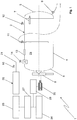
Figure 1 is a partial diagram of a vehicle for transporting and unloading flammable substances manageable using the method of the present invention; -
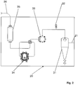
Figure 2 is a detailed diagram of a component of the diagram inFigure 1 . - The accompanying
figure 1 partially schematically shows avehicle 1 for transporting hazardous substances, such as muddy waste.Vehicle 1 includes atank 2 elongated in shape according to a longitudinal axis X, consisting mainly of acylindrical skirt 4 and two axially oppositerounded bottoms Tank 2 has a total volume equal to V and may be used to hold and transport hazardous substances susceptible of forming mixtures of explosive gases or vapours in at least one upper portion 2a oftank 2. The volume of the upper portion 2a corresponds to a volume to be ventilated Vv. - The first
curved bottom 5 may be opened by a plurality of hydraulic cylinders 7 (only onecylinder 7 is shown in the diagram infigure 1 ) interposed between the firstcurved bottom 5 and thecylindrical skirt 4. The secondcurved bottom 6 is connected to a tippinghydraulic cylinder 8 which may be used for tiltingtank 2 and subsequently emptying it through a lower loading/unloadingvalve 9 located in the lower side of the firstcurved bottom 5. The same lower loading/unloading valve 9 may also be used forcharging tank 2 from the bottom. The loading or unloading oftank 2 may alternatively be through an upper loading/unloadingvalve 11 located in the upper side ofskirt 4. - On the upper side of
skirt 4 there are also provided: - a
first purging valve 12 for connecting the upper portion 2a oftank 2 with the atmosphere; - a
manhole 13 for inspectingtank 2. - an intercepting
valve 14 for connectingtank 2 to a pumping circuit 20 (figure 2 ). - A
pumping line 21 is provided between thepumping circuit 20 and theintercepting valve 14, provided with asecond purging valve 16 for connecting thepumping line 21 with the atmosphere. - The
pumping circuit 20 is connected, for the actuation thereof, toengine 25 ofvehicle 25.Engine 25 is further connected to anelectrical accumulator 26. Anelectrical circuit breaker 27 is interposed betweenengine 25 and theelectric accumulator 26 for allowing the latter to be optionally isolated fromengine 25 and from the electrical system ofvehicle 1. Theelectrical accumulator 26, through aselector 28, allows supplying an electro-hydraulic control unit 30 connected to the tippinghydraulic cylinder 8 for controlling the tilting oftank 2. The presence of theelectrical circuit breaker 27 and ofselector 28 allow carrying out the operations of unloading of vehicle 1 (e.g.: opening the loading/unloading valve 9 and tilting tank 2) withengine 25 off and isolated electrical system of vehicle 1 (by actuating the electrical circuit breaker 27). This operating mode allows eliminating any risk of ignition induced by the electro-hydraulic components installed invehicle 1. - The
pumping circuit 20 upstream of thepumping line 21, includes, respectively in series: - a
cyclone filter 31; - a
pressure control valve 32; - an
air filter 33; - a
pump 34; - an
unloading silencer 35; - an
unloading line 36. - The
pumping circuit 20 is not structurally and functionally described in more detail being per se known and conventional. For the purposes of the present invention, thepumping circuit 20 may also be of a different type, provided it is capable of generating a suction flow rate Qp from thepumping line 21. - The method of the present invention is based on the execution of a fixed number n (purging number) of atmospheric air change in the upper portion 2a of
tank 2, so that the gaseous mixture contained therein is diluted until conditions are reached which are certainly not hazardous from the point of view of flammability and explosiveness. - This is achieved through the opening of the
first purging valve 12 and of thetank intercepting valve 14 and the concurrent operation of thepumping circuit 20 in suction mode, with generation of the flow rate Qp, for a purging time tc corresponding to the predetermined n number of air changes. - Alternatively, according to another embodiment variant of the present invention, if a higher flow rate of incoming atmospheric air is required, the first
curved bottom 5 is opened by actuating thehydraulic cylinders 7. - Number n is set equal to 10 (or higher than 10). Such a value is determined starting from the initial assumption that the emission of hazardous vapours from the sludge in
tank 2 during the purging time tc is not significant compared to the amounts extracted through the generation of the flow rate Qp. It was estimated (table 1) that a purging number equal to 10 is sufficient to ensure a final concentration of explosive gases or vapors inside the tank lower than 0.2% by volume compared to the atmospheric air.Table 1 n Concentration 0 100% 1 50% 2 25% 3 12.5% 4 6.3% 5 3.2% 6 1.6% 7 0.8% 8 0.4% 9 0.2% 10 0.1% - The definition of the purging number n conservatively considers that the suction of an amount of vapours or gases from
tank 2 equal to volume V (upper portion 2a coincident with the entire inside volume of tank 2), resulting in the introduction of clean air, causes a reduction in the inside concentration equal to 50% of the initial concentration. The conclusion is conservative since we start from the assumption that the initial concentration of vapor volume is equal to 100% of the available volume V, that the volume available for gases or vapours is the entire tank volume and that the clean air replaces the mixture present inside the tank by a percentage not exceeding 50%. The introduction of a second volume of air equal to volume V oftank 2 causes an effect of further division of inside concentration of the mixture that is therefore reduced to 25%, and going on (table 1), a concentration of 0.1% is reached after the introduction of the tenth air volume. - The above allows having a final concentration of gas inside the tank volume which is less than or equal to a quarter of the lower explosive limit (LEL) for gases which comply with the following ratio A:

- Ratio A is respected by all the gases of interest for the purposes of the present invention, being 0.8% the LEL of octane.
- The hypothesis proposed above, i.e. that the emission of flammable vapours from sludge in
tank 2 during the purging time tc is not significant, is not realistic but it is necessary to quantify an emission flow rate of vapor or gas Qg, generated by the liquid or solid phases of said flammable substances in contact with the upper portion 2a which contains the gases or vapours. Such a calculation may be done using regulatory models (IEC EN 60079-10-1: 2008 concerning the classification of places with explosive atmospheres and CEI 31-35:2012 National guide to IEC EN 60079-10-1) and making some conservative assumptions: - transport of pure liquid substance with particularly low lower explosive limit (LEL 0.8%), relatively low flashpoint temperature (13 °C) and relatively high vapor pressure (1544 Pa at 20 °C) (the figures given are related to octane);
- maximum permissible temperature for the liquid phase equal to 50 °C.
- the liquid inside
tank 2 is deemed to be contained in a pool having defined boundaries (the walls of the tank) and touched by the atmospheric air used for the purging itself. - On the basis of formula GB 4.4-1 of CEI 31-35:2012, the following is calculated:

- S is the liquid free surface;
- wa is the velocity of the air that touches the liquid;
- fSE is the ventilation effectiveness factor assumed to be equal to 1 in consideration that there are significant obstacles to air circulation inside the tank;
- M is the molar mass of the substance considered;
- pa is atmospheric pressure;
- pv is the vapor pressure at the temperature considered;
- R is the ideal gas constant;
- T is the absolute temperature in Kelvin degrees of the liquid;
- req corresponds to twice the surface of the liquid divided by its perimeter.
- The purging time tc may be calculated as:

- Upon completion of the purging operation, the
pumping circuit 20 is stopped and the valves to the outside oftank 2 are closed (loading/unloading valves valve 12 and intercepting valve 14) so thattank 2 is isolated from the external atmosphere. In this operating condition, the model described in the previous paragraph for determining the vapor emission flow rate is still applicable. The opening of thetank 2 and the consequent must be carried out within an opening time limit ta to prevent the new formation of the explosive mixture. - Such a time limit ta is calculable by means of:

- Ratio B may also be used to calculate a second purging time tv for washing the
pumping line 21 and thepumping circuit 20, i.e. for the dilution of the explosive gases therein due to the dilution process of the explosive mixture present intank 2. This is obtained by opening thesecond purging valve 16, closing the interceptingvalve 14 and at the same time by actuating thepumping circuit 20 in suction mode for a time tv equal to:
pumping line 21 and of thepumping circuit 20. It is clear that ratio D corresponds to B, setting Vv = VI and Qg = 0. - The method of the present invention therefore allows the achievement of the objects set out with reference to the above-mentioned prior art, allowing a fully safe operation of
tank 2 without using sensors for the measurement of concentration.
Claims (5)
- A method for safely managing flammable substances contained in a transport vehicle (1), said vehicle (1) comprising at least one volume to be ventilated (Vv) susceptible of containing a mixture of explosive vapours or gases, said method comprising the steps of:- putting said volume to be ventilated (Vv) into communication with the atmosphere;- calculating an explosive mixture flow rate (Qdan) emitted in a liquid and/or solid phase by said flammable substances in contact with said volume to be ventilated (Vv);- actuating a pumping circuit (20) for aspirating an intake flow rate (Qp) from said volume to be ventilated (Vv);- maintaining said intake flow rate (Qp) for a purging time (tc) calculated by means of the following ratio:

- A method according to claim 1, wherein said volume to be ventilated (Vv) is an upper portion (2a) of a tank (2) of said vehicle (1), wherein said step of putting said upper portion (2a) into communication with the atmosphere is actuated by opening a purging valve (12) or a bottom (5) of said tank (2) and wherein said pumping circuit (20) is put into communication with said upper portion (2a) by opening an intercepting valve (14).
- A method according to claim 1, wherein said volume to be ventilated (Vv) is the total volume (VI) of a pipe to be ventilated, wherein said step of putting said volume to be ventilated (VI) into communication with the atmosphere is actuated by opening a second purging valve (16) and wherein said pumping circuit (20) is isolated from a tank (2) containing said flammable substances by closing an intercepting valve (14).
- A method according to claim 2, wherein said method comprises the further steps of stopping said pumping circuit (20) and emptying said tank (2).
- A method according to claim 4, wherein a step of waiting wherein said tank (2) is isolated from the external atmosphere is provided between said steps of stopping said pumping circuit (20) and of emptying said tank (2), said step of waiting being maintained for a maximum waiting time (ta) calculated by means of the following ratio:

Applications Claiming Priority (1)
| Application Number | Priority Date | Filing Date | Title |
|---|---|---|---|
| IT000254A ITPD20130254A1 (en) | 2013-09-19 | 2013-09-19 | METHOD FOR SAFETY MANAGEMENT OF FLAMMABLE SUBSTANCES |
Publications (3)
| Publication Number | Publication Date |
|---|---|
| EP2851241A2 EP2851241A2 (en) | 2015-03-25 |
| EP2851241A3 EP2851241A3 (en) | 2016-11-30 |
| EP2851241B1 true EP2851241B1 (en) | 2018-05-30 |
Family
ID=49817175
Family Applications (1)
| Application Number | Title | Priority Date | Filing Date |
|---|---|---|---|
| EP14185528.8A Active EP2851241B1 (en) | 2013-09-19 | 2014-09-19 | Method for safely managing flammable substances |
Country Status (2)
| Country | Link |
|---|---|
| EP (1) | EP2851241B1 (en) |
| IT (1) | ITPD20130254A1 (en) |
Family Cites Families (3)
| Publication number | Priority date | Publication date | Assignee | Title |
|---|---|---|---|---|
| FR2839493B1 (en) * | 2002-05-10 | 2004-07-09 | Rivard Sa | PROCESS FOR AUTHORIZING THE OPERATION OF A HAZARDOUS WASTE TANK OPERATING IN VACUUM AS WELL AS A DEVICE FOR CARRYING OUT THIS PROCESS |
| FR2864523B1 (en) * | 2003-12-24 | 2006-12-22 | Rivard | PROCESS FOR PREVENTING THE FORMATION OF AN INSALUBRE AND / OR EXPLOSIVE ATMOSPHERE IN THE ENVIRONMENT OF A CISTERN AND A DEVICE FOR CARRYING OUT SAID METHOD |
| EP2181888A1 (en) * | 2008-10-28 | 2010-05-05 | Cappellotto S.p.A. | Suction apparatus for suctioning combustible material |
-
2013
- 2013-09-19 IT IT000254A patent/ITPD20130254A1/en unknown
-
2014
- 2014-09-19 EP EP14185528.8A patent/EP2851241B1/en active Active
Non-Patent Citations (1)
| Title |
|---|
| None * |
Also Published As
| Publication number | Publication date |
|---|---|
| EP2851241A2 (en) | 2015-03-25 |
| ITPD20130254A1 (en) | 2015-03-20 |
| EP2851241A3 (en) | 2016-11-30 |
Similar Documents
| Publication | Publication Date | Title |
|---|---|---|
| US9586805B1 (en) | Mobile distribution station with aisle walkway | |
| CN101292144B (en) | Method and apparatus for continuously monitoring interstitial regions in gasoline storage facilities and pipelines | |
| JP2009120204A (en) | Low flash point fuel storage system | |
| US20200108429A1 (en) | Sintered Wave Porous Media Treatment, Apparatus and Process for Removal of Organic Compounds and Nondestructive Removal and Condensation of Per and Polyfluoroalkyl Substances and related fluorinated compounds | |
| CN204642779U (en) | A kind of double-layer tank that can prevent oil product from volatilizing | |
| CN103985426B (en) | The wet solid waste treatment method of nuclear facilities radioactivity | |
| KR20180087397A (en) | A method and system for determining time data relating to a non-combustion exhaust process of a fuel gas from a gas tank of a vehicle | |
| EP2851241B1 (en) | Method for safely managing flammable substances | |
| CN203190729U (en) | Full-automatic gas recovery charging device | |
| CN109649699A (en) | The pre- loading system of hydrogen peroxide and aircraft | |
| US10968585B2 (en) | Vacuum installation for industrial vacuum processes | |
| RU2516849C1 (en) | Method of studying procedure of tank cleaning from oil residues | |
| JP2007212412A (en) | Gas recovery container for fine decompression of buried underground tank internal pressure | |
| JP2012202973A (en) | Treatment device for treated object containing flammable gas | |
| CN106969260A (en) | A kind of LNG cold pump sump gas extraction system and control method | |
| KR20160023205A (en) | Method and Apparatus for Predicting Greenhouse Gases Emissions | |
| EP1108880A3 (en) | Method and system for predicting stabilized time duration of vapor leak detection pump strokes | |
| US20180347902A1 (en) | Method and system for drying an enclosure | |
| RU127662U1 (en) | LABORATORY INSTALLATION FOR RESEARCH OF THE PROCESS OF CLEANING RESERVOIRS FROM RESIDUALS OF OIL PRODUCTS | |
| CN102477760A (en) | Water supply apparatus | |
| JP7320463B2 (en) | DRYING APPARATUS AND METHOD FOR RADIOACTIVE MATERIAL STORAGE CONTAINER | |
| CN107670078A (en) | Vacuum system and oxirane system and device | |
| KR102047835B1 (en) | Drying apparatus of sludge | |
| CN104370429B (en) | The automatic drying method of mud | |
| CN215439658U (en) | Epoxypropane tank wagon system of unloading |
Legal Events
| Date | Code | Title | Description |
|---|---|---|---|
| PUAI | Public reference made under article 153(3) epc to a published international application that has entered the european phase |
Free format text: ORIGINAL CODE: 0009012 |
|
| 17P | Request for examination filed |
Effective date: 20140919 |
|
| AK | Designated contracting states |
Kind code of ref document: A2 Designated state(s): AL AT BE BG CH CY CZ DE DK EE ES FI FR GB GR HR HU IE IS IT LI LT LU LV MC MK MT NL NO PL PT RO RS SE SI SK SM TR |
|
| AX | Request for extension of the european patent |
Extension state: BA ME |
|
| PUAL | Search report despatched |
Free format text: ORIGINAL CODE: 0009013 |
|
| AK | Designated contracting states |
Kind code of ref document: A3 Designated state(s): AL AT BE BG CH CY CZ DE DK EE ES FI FR GB GR HR HU IE IS IT LI LT LU LV MC MK MT NL NO PL PT RO RS SE SI SK SM TR |
|
| AX | Request for extension of the european patent |
Extension state: BA ME |
|
| RIC1 | Information provided on ipc code assigned before grant |
Ipc: B60P 3/22 20060101AFI20161026BHEP Ipc: B65D 90/34 20060101ALI20161026BHEP |
|
| RBV | Designated contracting states (corrected) |
Designated state(s): AL AT BE BG CH CY CZ DE DK EE ES FI FR GB GR HR HU IE IS IT LI LT LU LV MC MK MT NL NO PL PT RO RS SE SI SK SM TR |
|
| R17P | Request for examination filed (corrected) |
Effective date: 20170529 |
|
| GRAP | Despatch of communication of intention to grant a patent |
Free format text: ORIGINAL CODE: EPIDOSNIGR1 |
|
| INTG | Intention to grant announced |
Effective date: 20171214 |
|
| GRAS | Grant fee paid |
Free format text: ORIGINAL CODE: EPIDOSNIGR3 |
|
| GRAA | (expected) grant |
Free format text: ORIGINAL CODE: 0009210 |
|
| AK | Designated contracting states |
Kind code of ref document: B1 Designated state(s): AL AT BE BG CH CY CZ DE DK EE ES FI FR GB GR HR HU IE IS IT LI LT LU LV MC MK MT NL NO PL PT RO RS SE SI SK SM TR |
|
| REG | Reference to a national code |
Ref country code: GB Ref legal event code: FG4D |
|
| REG | Reference to a national code |
Ref country code: CH Ref legal event code: EP |
|
| REG | Reference to a national code |
Ref country code: AT Ref legal event code: REF Ref document number: 1003269 Country of ref document: AT Kind code of ref document: T Effective date: 20180615 |
|
| REG | Reference to a national code |
Ref country code: IE Ref legal event code: FG4D |
|
| REG | Reference to a national code |
Ref country code: DE Ref legal event code: R096 Ref document number: 602014026105 Country of ref document: DE |
|
| REG | Reference to a national code |
Ref country code: FR Ref legal event code: PLFP Year of fee payment: 5 |
|
| REG | Reference to a national code |
Ref country code: CH Ref legal event code: NV Representative=s name: IPWAY DI FRANCESCO FABIO AND CO., CH |
|
| REG | Reference to a national code |
Ref country code: NL Ref legal event code: MP Effective date: 20180530 |
|
| REG | Reference to a national code |
Ref country code: LT Ref legal event code: MG4D |
|
| PG25 | Lapsed in a contracting state [announced via postgrant information from national office to epo] |
Ref country code: SE Free format text: LAPSE BECAUSE OF FAILURE TO SUBMIT A TRANSLATION OF THE DESCRIPTION OR TO PAY THE FEE WITHIN THE PRESCRIBED TIME-LIMIT Effective date: 20180530 Ref country code: ES Free format text: LAPSE BECAUSE OF FAILURE TO SUBMIT A TRANSLATION OF THE DESCRIPTION OR TO PAY THE FEE WITHIN THE PRESCRIBED TIME-LIMIT Effective date: 20180530 Ref country code: LT Free format text: LAPSE BECAUSE OF FAILURE TO SUBMIT A TRANSLATION OF THE DESCRIPTION OR TO PAY THE FEE WITHIN THE PRESCRIBED TIME-LIMIT Effective date: 20180530 Ref country code: NO Free format text: LAPSE BECAUSE OF FAILURE TO SUBMIT A TRANSLATION OF THE DESCRIPTION OR TO PAY THE FEE WITHIN THE PRESCRIBED TIME-LIMIT Effective date: 20180830 Ref country code: BG Free format text: LAPSE BECAUSE OF FAILURE TO SUBMIT A TRANSLATION OF THE DESCRIPTION OR TO PAY THE FEE WITHIN THE PRESCRIBED TIME-LIMIT Effective date: 20180830 Ref country code: FI Free format text: LAPSE BECAUSE OF FAILURE TO SUBMIT A TRANSLATION OF THE DESCRIPTION OR TO PAY THE FEE WITHIN THE PRESCRIBED TIME-LIMIT Effective date: 20180530 Ref country code: CY Free format text: LAPSE BECAUSE OF FAILURE TO SUBMIT A TRANSLATION OF THE DESCRIPTION OR TO PAY THE FEE WITHIN THE PRESCRIBED TIME-LIMIT Effective date: 20180530 |
|
| PG25 | Lapsed in a contracting state [announced via postgrant information from national office to epo] |
Ref country code: HR Free format text: LAPSE BECAUSE OF FAILURE TO SUBMIT A TRANSLATION OF THE DESCRIPTION OR TO PAY THE FEE WITHIN THE PRESCRIBED TIME-LIMIT Effective date: 20180530 Ref country code: RS Free format text: LAPSE BECAUSE OF FAILURE TO SUBMIT A TRANSLATION OF THE DESCRIPTION OR TO PAY THE FEE WITHIN THE PRESCRIBED TIME-LIMIT Effective date: 20180530 Ref country code: GR Free format text: LAPSE BECAUSE OF FAILURE TO SUBMIT A TRANSLATION OF THE DESCRIPTION OR TO PAY THE FEE WITHIN THE PRESCRIBED TIME-LIMIT Effective date: 20180831 Ref country code: LV Free format text: LAPSE BECAUSE OF FAILURE TO SUBMIT A TRANSLATION OF THE DESCRIPTION OR TO PAY THE FEE WITHIN THE PRESCRIBED TIME-LIMIT Effective date: 20180530 |
|
| REG | Reference to a national code |
Ref country code: AT Ref legal event code: MK05 Ref document number: 1003269 Country of ref document: AT Kind code of ref document: T Effective date: 20180530 |
|
| PG25 | Lapsed in a contracting state [announced via postgrant information from national office to epo] |
Ref country code: NL Free format text: LAPSE BECAUSE OF FAILURE TO SUBMIT A TRANSLATION OF THE DESCRIPTION OR TO PAY THE FEE WITHIN THE PRESCRIBED TIME-LIMIT Effective date: 20180530 |
|
| PG25 | Lapsed in a contracting state [announced via postgrant information from national office to epo] |
Ref country code: DK Free format text: LAPSE BECAUSE OF FAILURE TO SUBMIT A TRANSLATION OF THE DESCRIPTION OR TO PAY THE FEE WITHIN THE PRESCRIBED TIME-LIMIT Effective date: 20180530 Ref country code: AT Free format text: LAPSE BECAUSE OF FAILURE TO SUBMIT A TRANSLATION OF THE DESCRIPTION OR TO PAY THE FEE WITHIN THE PRESCRIBED TIME-LIMIT Effective date: 20180530 Ref country code: EE Free format text: LAPSE BECAUSE OF FAILURE TO SUBMIT A TRANSLATION OF THE DESCRIPTION OR TO PAY THE FEE WITHIN THE PRESCRIBED TIME-LIMIT Effective date: 20180530 Ref country code: SK Free format text: LAPSE BECAUSE OF FAILURE TO SUBMIT A TRANSLATION OF THE DESCRIPTION OR TO PAY THE FEE WITHIN THE PRESCRIBED TIME-LIMIT Effective date: 20180530 Ref country code: RO Free format text: LAPSE BECAUSE OF FAILURE TO SUBMIT A TRANSLATION OF THE DESCRIPTION OR TO PAY THE FEE WITHIN THE PRESCRIBED TIME-LIMIT Effective date: 20180530 Ref country code: CZ Free format text: LAPSE BECAUSE OF FAILURE TO SUBMIT A TRANSLATION OF THE DESCRIPTION OR TO PAY THE FEE WITHIN THE PRESCRIBED TIME-LIMIT Effective date: 20180530 Ref country code: PL Free format text: LAPSE BECAUSE OF FAILURE TO SUBMIT A TRANSLATION OF THE DESCRIPTION OR TO PAY THE FEE WITHIN THE PRESCRIBED TIME-LIMIT Effective date: 20180530 |
|
| PG25 | Lapsed in a contracting state [announced via postgrant information from national office to epo] |
Ref country code: SM Free format text: LAPSE BECAUSE OF FAILURE TO SUBMIT A TRANSLATION OF THE DESCRIPTION OR TO PAY THE FEE WITHIN THE PRESCRIBED TIME-LIMIT Effective date: 20180530 |
|
| REG | Reference to a national code |
Ref country code: DE Ref legal event code: R097 Ref document number: 602014026105 Country of ref document: DE |
|
| PLBE | No opposition filed within time limit |
Free format text: ORIGINAL CODE: 0009261 |
|
| STAA | Information on the status of an ep patent application or granted ep patent |
Free format text: STATUS: NO OPPOSITION FILED WITHIN TIME LIMIT |
|
| PG25 | Lapsed in a contracting state [announced via postgrant information from national office to epo] |
Ref country code: MC Free format text: LAPSE BECAUSE OF FAILURE TO SUBMIT A TRANSLATION OF THE DESCRIPTION OR TO PAY THE FEE WITHIN THE PRESCRIBED TIME-LIMIT Effective date: 20180530 |
|
| 26N | No opposition filed |
Effective date: 20190301 |
|
| PG25 | Lapsed in a contracting state [announced via postgrant information from national office to epo] |
Ref country code: SI Free format text: LAPSE BECAUSE OF FAILURE TO SUBMIT A TRANSLATION OF THE DESCRIPTION OR TO PAY THE FEE WITHIN THE PRESCRIBED TIME-LIMIT Effective date: 20180530 |
|
| REG | Reference to a national code |
Ref country code: BE Ref legal event code: MM Effective date: 20180930 |
|
| REG | Reference to a national code |
Ref country code: IE Ref legal event code: MM4A |
|
| PG25 | Lapsed in a contracting state [announced via postgrant information from national office to epo] |
Ref country code: LU Free format text: LAPSE BECAUSE OF NON-PAYMENT OF DUE FEES Effective date: 20180919 |
|
| PG25 | Lapsed in a contracting state [announced via postgrant information from national office to epo] |
Ref country code: IE Free format text: LAPSE BECAUSE OF NON-PAYMENT OF DUE FEES Effective date: 20180919 |
|
| PG25 | Lapsed in a contracting state [announced via postgrant information from national office to epo] |
Ref country code: BE Free format text: LAPSE BECAUSE OF NON-PAYMENT OF DUE FEES Effective date: 20180930 |
|
| PG25 | Lapsed in a contracting state [announced via postgrant information from national office to epo] |
Ref country code: AL Free format text: LAPSE BECAUSE OF FAILURE TO SUBMIT A TRANSLATION OF THE DESCRIPTION OR TO PAY THE FEE WITHIN THE PRESCRIBED TIME-LIMIT Effective date: 20180530 |
|
| PG25 | Lapsed in a contracting state [announced via postgrant information from national office to epo] |
Ref country code: MT Free format text: LAPSE BECAUSE OF NON-PAYMENT OF DUE FEES Effective date: 20180919 |
|
| PG25 | Lapsed in a contracting state [announced via postgrant information from national office to epo] |
Ref country code: TR Free format text: LAPSE BECAUSE OF FAILURE TO SUBMIT A TRANSLATION OF THE DESCRIPTION OR TO PAY THE FEE WITHIN THE PRESCRIBED TIME-LIMIT Effective date: 20180530 |
|
| PG25 | Lapsed in a contracting state [announced via postgrant information from national office to epo] |
Ref country code: HU Free format text: LAPSE BECAUSE OF FAILURE TO SUBMIT A TRANSLATION OF THE DESCRIPTION OR TO PAY THE FEE WITHIN THE PRESCRIBED TIME-LIMIT; INVALID AB INITIO Effective date: 20140919 Ref country code: PT Free format text: LAPSE BECAUSE OF FAILURE TO SUBMIT A TRANSLATION OF THE DESCRIPTION OR TO PAY THE FEE WITHIN THE PRESCRIBED TIME-LIMIT Effective date: 20180530 |
|
| PG25 | Lapsed in a contracting state [announced via postgrant information from national office to epo] |
Ref country code: MK Free format text: LAPSE BECAUSE OF NON-PAYMENT OF DUE FEES Effective date: 20180530 |
|
| PG25 | Lapsed in a contracting state [announced via postgrant information from national office to epo] |
Ref country code: IS Free format text: LAPSE BECAUSE OF FAILURE TO SUBMIT A TRANSLATION OF THE DESCRIPTION OR TO PAY THE FEE WITHIN THE PRESCRIBED TIME-LIMIT Effective date: 20180930 |
|
| P01 | Opt-out of the competence of the unified patent court (upc) registered |
Effective date: 20230529 |
|
| PGFP | Annual fee paid to national office [announced via postgrant information from national office to epo] |
Ref country code: DE Payment date: 20240925 Year of fee payment: 11 |
|
| PGFP | Annual fee paid to national office [announced via postgrant information from national office to epo] |
Ref country code: GB Payment date: 20240919 Year of fee payment: 11 |
|
| PGFP | Annual fee paid to national office [announced via postgrant information from national office to epo] |
Ref country code: FR Payment date: 20240923 Year of fee payment: 11 |
|
| PGFP | Annual fee paid to national office [announced via postgrant information from national office to epo] |
Ref country code: IT Payment date: 20240925 Year of fee payment: 11 |
|
| PGFP | Annual fee paid to national office [announced via postgrant information from national office to epo] |
Ref country code: CH Payment date: 20241001 Year of fee payment: 11 |