EP2851117A1 - Hollow fiber membrane module - Google Patents
Hollow fiber membrane module Download PDFInfo
- Publication number
- EP2851117A1 EP2851117A1 EP20130791013 EP13791013A EP2851117A1 EP 2851117 A1 EP2851117 A1 EP 2851117A1 EP 20130791013 EP20130791013 EP 20130791013 EP 13791013 A EP13791013 A EP 13791013A EP 2851117 A1 EP2851117 A1 EP 2851117A1
- Authority
- EP
- European Patent Office
- Prior art keywords
- hollow fiber
- fiber membrane
- bundling tube
- membrane module
- parts
- Prior art date
- Legal status (The legal status is an assumption and is not a legal conclusion. Google has not performed a legal analysis and makes no representation as to the accuracy of the status listed.)
- Withdrawn
Links
Images
Classifications
-
- B—PERFORMING OPERATIONS; TRANSPORTING
- B01—PHYSICAL OR CHEMICAL PROCESSES OR APPARATUS IN GENERAL
- B01D—SEPARATION
- B01D63/00—Apparatus in general for separation processes using semi-permeable membranes
- B01D63/02—Hollow fibre modules
- B01D63/021—Manufacturing thereof
- B01D63/022—Encapsulating hollow fibres
-
- B—PERFORMING OPERATIONS; TRANSPORTING
- B01—PHYSICAL OR CHEMICAL PROCESSES OR APPARATUS IN GENERAL
- B01D—SEPARATION
- B01D63/00—Apparatus in general for separation processes using semi-permeable membranes
- B01D63/02—Hollow fibre modules
-
- B—PERFORMING OPERATIONS; TRANSPORTING
- B01—PHYSICAL OR CHEMICAL PROCESSES OR APPARATUS IN GENERAL
- B01D—SEPARATION
- B01D65/00—Accessories or auxiliary operations, in general, for separation processes or apparatus using semi-permeable membranes
- B01D65/003—Membrane bonding or sealing
-
- B—PERFORMING OPERATIONS; TRANSPORTING
- B01—PHYSICAL OR CHEMICAL PROCESSES OR APPARATUS IN GENERAL
- B01D—SEPARATION
- B01D69/00—Semi-permeable membranes for separation processes or apparatus characterised by their form, structure or properties; Manufacturing processes specially adapted therefor
- B01D69/08—Hollow fibre membranes
-
- B—PERFORMING OPERATIONS; TRANSPORTING
- B01—PHYSICAL OR CHEMICAL PROCESSES OR APPARATUS IN GENERAL
- B01D—SEPARATION
- B01D71/00—Semi-permeable membranes for separation processes or apparatus characterised by the material; Manufacturing processes specially adapted therefor
- B01D71/02—Inorganic material
- B01D71/021—Carbon
-
- B—PERFORMING OPERATIONS; TRANSPORTING
- B01—PHYSICAL OR CHEMICAL PROCESSES OR APPARATUS IN GENERAL
- B01D—SEPARATION
- B01D2313/00—Details relating to membrane modules or apparatus
- B01D2313/04—Specific sealing means
- B01D2313/041—Gaskets or O-rings
-
- B—PERFORMING OPERATIONS; TRANSPORTING
- B01—PHYSICAL OR CHEMICAL PROCESSES OR APPARATUS IN GENERAL
- B01D—SEPARATION
- B01D2313/00—Details relating to membrane modules or apparatus
- B01D2313/20—Specific housing
- B01D2313/201—Closed housing, vessels or containers
-
- B—PERFORMING OPERATIONS; TRANSPORTING
- B01—PHYSICAL OR CHEMICAL PROCESSES OR APPARATUS IN GENERAL
- B01D—SEPARATION
- B01D2313/00—Details relating to membrane modules or apparatus
- B01D2313/21—Specific headers, end caps
Definitions
- the present invention relates to a hollow fiber membrane module. More particularly, the present invention relates to a hollow fiber membrane module capable of preventing damage effectively on a hollow fiber membrane or a bundling tube due to expansion or contraction of the hollow fiber membrane to be caused by change of an external environment such as temperature.
- a hollow fiber membrane has many porous structures formed in the membrane in terms of its structure, so that it expands or contracts largely as a result of change of an external environment such as temperature.
- a hollow fiber membrane may be subjected to process such as filtration, condensation or degassing of a solvent in terms of its function. In this case, the material of the hollow fiber membrane itself may be swelled by the solvent.
- a hollow fiber membrane module includes hundreds or thousands of such hollow fiber membranes housed in a bundling tube. Even though the contractile force of one hollow fiber membrane may be small, the contractile forces of all hollow fiber membranes housed in the bundling tube act on the bundling tube because all the housed hollow fiber membranes expand or contract.
- the hollow fiber membrane module comprising including the bundling tube housing the hollow fiber membranes and potting parts formed at both ends of the bundling tube
- expansion of the hollow fiber membranes in the longitudinal direction may make the hollow fiber membranes protrude from the bundling tube as a result of an integral structure of the bundling tube
- the hollow fiber membranes may be pressed against a fence for prevention of the protrusion to be damaged, or the contraction of the hollow fiber membranes in the longitudinal direction may damage the hollow fiber membranes or the bundling tube.
- An object of the present invention is to provide a hollow fiber membrane module capable of preventing damage effectively on a hollow fiber membrane or a bundling tube due to expansion or contraction of the hollow fiber membrane to be caused by change of an external environment such as temperature.
- a hollow fiber membrane module comprising a bundling tube including a body part and head parts placed at both terminals of the body part and O-rings with which the bundling tube is fitted into a housing being attached to outer circumferential surfaces of the head parts, wherein at least one of the head parts are divided into two in a place closer to a terminal of the bundling tube than places where the O-rings are attached while maintaining a cylindrical shape of the head part, and the divided parts have a slidable structure while maintaining a coupled condition therebetween that forms the cylindrical shape.
- the slidable cylindrical body divided parts are arranged in the place closer to the terminal than the places where the O-rings used for fitting the bundling tube into the housing are attached. This achieves an excellent effect in that it is capable of preventing damage effectively on a hollow fiber membrane or the bundling tube due to expansion or contraction of the hollow fiber membrane to be caused by change of an external environment such as temperature.
- Patent document 1 suggests a humidifying device capable of preventing damage on an inner pipe due to heat contraction of a hollow fiber membrane.
- the humidifying device includes a bundle of hollow fiber membranes, a housing that houses the bundle, and the inner pipe arranged in the housing.
- the inner pipe causes a first fluid to flow along the outside of each hollow fiber membrane.
- a second fluid flows in the inner hollow portion of each hollow fiber membrane, moisture is transferred between the first and second fluids.
- a coupled member is provided in the housing that is coupled to the inner pipe in a manner that allows the coupled member to make sliding movement with the inner pipe.
- the sliding mechanism is provided with the intension of preventing damage on the inner pipe to be caused if the hollow fiber membranes expand or contract in the longitudinal direction during "modularization.”
- sealing members O-rings
- both of these head parts at both terminals with the sealing members become hard to make sliding movement.
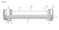
- Fig. 1 is a partial half-cut front view showing an embodiment of a hollow fiber membrane module according to the present invention.
- a hollow fiber membrane module according to the present invention comprises a bundling tube including a body part and head parts joined to both terminals of the body part, and O-rings with which the bundling tube is fitted into a housing being attached to outer circumferential surfaces of the head parts, wherein at least one of the head parts are divided into two in a place closer to a terminal of the bundling tube than places where the O-ring are attached while maintaining a cylindrical shape of the head part, and the divided parts have a slidable structure while maintaining a coupled condition therebetween that forms the cylindrical shape.
- a hollow fiber membrane module 1 includes a bundling tube body part 2 housing a hollow fiber membrane group 4 inside, and bundling tube head parts 3 and 3' provided at both terminals of the bundling tube body part 2.
- the bundling tube head parts 3 and 3' let the hollow fiber membrane group pass therethrough.
- the bundling tube head parts 3 and 3' each have a potting part 5 that fixes the hollow fiber membrane group.
- the bundling tube body part 2 is formed of a cylindrical member of an elongated tube shape having an opening part formed in a side surface of the bundling tube body part 2 in which a fluid is to flow.
- the bundling tube body part 2 may be provided with opening parts 2a in the shape of long holes formed in two symmetric places on both sides of the tube with respect to the central axis of the tube to extend along the substantially entire length of the tube.
- the opening parts 2a are arranged in a symmetric pattern with respect to the center axis.
- the bundling tube body part 2 may also be provided with opening parts in the shape of ovals or short holes formed by cutting the bundling tube body part 2 in four places in total on both sides of the tube near both end portions thereof and symmetric with respect to the central axis of the tube. These opening parts are arranged in a bilaterally symmetric pattern (see Figs. 2 and 3 of patent document 2).
- opening parts in the shape of long holes or short holes formed in the side surface of the body part are intended for outflow and inflow of a fluid through which a fluid such as gas is made to contact the hollow fiber membrane group and to pass through the hollow fiber membrane group.
- the opening part formed in one place may achieve the purpose of outflow and inflow of a fluid. Meanwhile, it is preferable that opening parts in multiple places be arranged in a bilaterally symmetric pattern.
- the bundling tube body part 2 can be made of an airtight material having resistance to heat and having a thermal expansion coefficient same as or close to that of hollow fiber membranes housed in the bundling tube body part 2.
- the bundling tube body part 2 is provided with the opening parts 2a for outflow and inflow of a fluid equally arranged in symmetric places on both sides of the tube body in a symmetric pattern.
- This can minimize the occurrence of flexure or deflection due to nonuniform thermal expansion that may occur in a structure where the opening parts 2a are formed in an asymmetric pattern.
- this symmetric pattern suppresses thermal deformation of the bundling tube body part 2, so that the occurrence of stress concentration on a different member such as a hollow fiber membrane due to the influence of this thermal deformation can be prevented.
- this symmetric pattern effectively acts to avoid a situation such as damage on the module.
- a hollow fiber membrane group including a bundle of hundreds or thousands of hollow fiber membranes such as porous carbon hollow fiber membranes or porous ceramic hollow fiber membranes is housed in the bundling tube body part 2.
- the housed hollow fiber membrane group passes through the bundling tube head parts 3 and 3' and is fixed by the potting parts 5.
- the bundling tube head parts 3 and 3' are made of the same material as the bundling tube body part 2.
- the porous carbon hollow fiber membranes to be used may be formed by sintering a resin-based material such as a polyphenyleneoxide-based material, a polyimide-based material, a polysulphone-based material, or a cellulose-based material.
- the porous ceramic hollow fiber membranes to be used may be made of Al 2 O 3 , Y 2 O 3 , MgO, SiO 2 , Si 3 N 4 or ZrO 2 , for example.
- a sliding part 6 is formed at one or both of the bundling tube head parts 3 and 3' provided at both terminals of the bundling tube body part 2.
- the bundling tube head part is divided into two while maintaining a cylindrical shape of the bundling tube head part.
- the divided parts are provided with the sliding part 6.
- the sliding part 6 can deal with the volume change by making sliding movement while maintaining a coupled condition between the divided parts that forms the cylindrical shape.
- Providing the sliding part 6 makes the hollow fiber membrane module expand or contract in the longitudinal direction in response to expansion or contraction of hollow fiber membranes in the longitudinal direction while the coupled condition between the divided parts is maintained.
- Maintaining the coupled condition that forms the cylindrical shape mentioned herein means that divided bundling tube head members contact each other at an inner circumferential surface of one of the head members and an outer circumferential surface of the other head member.
- the sliding part 6 may have any structure as long as it can deal with change in the volume inside the bundling tube while maintaining the coupled condition that forms the cylindrical shape.
- each of these cylindrical bodies are given steps formed at corresponding end portions and the cylindrical bodies are coupled while fitting these steps each other.
- one of the cylindrical bodies has an outer diameter same as the inner diameter of the other cylindrical body and the cylindrical bodies are coupled while fitting them each other.
- Patent document 3 discloses in Figs. 3 and 4 that divided parts formed by dividing a bundling tube into two have a sliding structure while maintaining a coupled condition therebetween.
- this sliding part is provided in a part corresponding to the bundling tube body part of the present invention, so that this embodiment is different from that of the present invention as an O-ring of this embodiment provided in a bundling tube head part makes a sliding mechanism hard to function.
- an O-ring 7" be attached to a coupled portion of the sliding part 6, specifically a portion where the divided bundling tube head members contact each other.
- the hollow fiber membrane module 1 of the aforementioned structure is fitted to a housing by attaching the bundling tube head parts 3 and 3' of the hollow fiber membrane module 1 via O-rings 7 and 7' as sealing members in a hermetically sealed manner.
- the O-rings 7 and 7' are arranged on the outer circumferential surfaces of the bundling tube head parts 3 ands 3'. If the bundling tube head parts 3 and 3' are provided with the sliding parts 6, the O-rings 7 and 7' are arranged in places closer to the bundling tube body part 2 than places where the sliding parts 6 are arranged.
Landscapes
- Chemical & Material Sciences (AREA)
- Chemical Kinetics & Catalysis (AREA)
- Inorganic Chemistry (AREA)
- Engineering & Computer Science (AREA)
- Manufacturing & Machinery (AREA)
- Separation Using Semi-Permeable Membranes (AREA)
Abstract
Description
- The present invention relates to a hollow fiber membrane module. More particularly, the present invention relates to a hollow fiber membrane module capable of preventing damage effectively on a hollow fiber membrane or a bundling tube due to expansion or contraction of the hollow fiber membrane to be caused by change of an external environment such as temperature.
- A hollow fiber membrane has many porous structures formed in the membrane in terms of its structure, so that it expands or contracts largely as a result of change of an external environment such as temperature. A hollow fiber membrane may be subjected to process such as filtration, condensation or degassing of a solvent in terms of its function. In this case, the material of the hollow fiber membrane itself may be swelled by the solvent.
- A hollow fiber membrane module includes hundreds or thousands of such hollow fiber membranes housed in a bundling tube. Even though the contractile force of one hollow fiber membrane may be small, the contractile forces of all hollow fiber membranes housed in the bundling tube act on the bundling tube because all the housed hollow fiber membranes expand or contract. Thus, in the hollow fiber membrane module comprising including the bundling tube housing the hollow fiber membranes and potting parts formed at both ends of the bundling tube, expansion of the hollow fiber membranes in the longitudinal direction may make the hollow fiber membranes protrude from the bundling tube as a result of an integral structure of the bundling tube, the hollow fiber membranes may be pressed against a fence for prevention of the protrusion to be damaged, or the contraction of the hollow fiber membranes in the longitudinal direction may damage the hollow fiber membranes or the bundling tube.
-
- Patent Document 1 :
JP-A-2006-64189 - Patent Document 2 :
JP-A-2008-238068 - Patent Document 3 :
JP-A-2006-61783 - An object of the present invention is to provide a hollow fiber membrane module capable of preventing damage effectively on a hollow fiber membrane or a bundling tube due to expansion or contraction of the hollow fiber membrane to be caused by change of an external environment such as temperature.
- The aforementioned object of the present invention is achieved by a hollow fiber membrane module comprising a bundling tube including a body part and head parts placed at both terminals of the body part and O-rings with which the bundling tube is fitted into a housing being attached to outer circumferential surfaces of the head parts, wherein at least one of the head parts are divided into two in a place closer to a terminal of the bundling tube than places where the O-rings are attached while maintaining a cylindrical shape of the head part, and the divided parts have a slidable structure while maintaining a coupled condition therebetween that forms the cylindrical shape.
- In the hollow fiber membrane module according to the present invention, the slidable cylindrical body divided parts are arranged in the place closer to the terminal than the places where the O-rings used for fitting the bundling tube into the housing are attached. This achieves an excellent effect in that it is capable of preventing damage effectively on a hollow fiber membrane or the bundling tube due to expansion or contraction of the hollow fiber membrane to be caused by change of an external environment such as temperature.
- Patent document 1 suggests a humidifying device capable of preventing damage on an inner pipe due to heat contraction of a hollow fiber membrane. The humidifying device includes a bundle of hollow fiber membranes, a housing that houses the bundle, and the inner pipe arranged in the housing. The inner pipe causes a first fluid to flow along the outside of each hollow fiber membrane. When a second fluid flows in the inner hollow portion of each hollow fiber membrane, moisture is transferred between the first and second fluids. In this humidifying device, a coupled member is provided in the housing that is coupled to the inner pipe in a manner that allows the coupled member to make sliding movement with the inner pipe.
- As described above in this humidifying device, the sliding mechanism is provided with the intension of preventing damage on the inner pipe to be caused if the hollow fiber membranes expand or contract in the longitudinal direction during "modularization." In this humidifying device, if sealing members (O-rings) are provided as seals for fixation at heads parts as in the present invention, both of these head parts at both terminals with the sealing members become hard to make sliding movement.
-
Fig. 1 is a partial half-cut front view showing an embodiment of a hollow fiber membrane module according to the present invention. - A hollow fiber membrane module according to the present invention comprises a bundling tube including a body part and head parts joined to both terminals of the body part, and O-rings with which the bundling tube is fitted into a housing being attached to outer circumferential surfaces of the head parts, wherein at least one of the head parts are divided into two in a place closer to a terminal of the bundling tube than places where the O-ring are attached while maintaining a cylindrical shape of the head part, and the divided parts have a slidable structure while maintaining a coupled condition therebetween that forms the cylindrical shape. The following describes an embodiment of the hollow fiber membrane module according to the present invention in detail by referring to the drawings.
- As shown in
Fig. 1 , a hollow fiber membrane module 1 includes a bundlingtube body part 2 housing a hollowfiber membrane group 4 inside, and bundlingtube head parts 3 and 3' provided at both terminals of the bundlingtube body part 2. The bundlingtube head parts 3 and 3' let the hollow fiber membrane group pass therethrough. The bundlingtube head parts 3 and 3' each have apotting part 5 that fixes the hollow fiber membrane group. As an example, the bundlingtube body part 2 is formed of a cylindrical member of an elongated tube shape having an opening part formed in a side surface of the bundlingtube body part 2 in which a fluid is to flow. The bundlingtube body part 2 may be provided with opening parts 2a in the shape of long holes formed in two symmetric places on both sides of the tube with respect to the central axis of the tube to extend along the substantially entire length of the tube. The opening parts 2a are arranged in a symmetric pattern with respect to the center axis. The bundlingtube body part 2 may also be provided with opening parts in the shape of ovals or short holes formed by cutting the bundlingtube body part 2 in four places in total on both sides of the tube near both end portions thereof and symmetric with respect to the central axis of the tube. These opening parts are arranged in a bilaterally symmetric pattern (see Figs. 2 and 3 of patent document 2). These opening parts in the shape of long holes or short holes formed in the side surface of the body part are intended for outflow and inflow of a fluid through which a fluid such as gas is made to contact the hollow fiber membrane group and to pass through the hollow fiber membrane group. The opening part formed in one place may achieve the purpose of outflow and inflow of a fluid. Meanwhile, it is preferable that opening parts in multiple places be arranged in a bilaterally symmetric pattern. The bundlingtube body part 2 can be made of an airtight material having resistance to heat and having a thermal expansion coefficient same as or close to that of hollow fiber membranes housed in the bundlingtube body part 2. - In this way, the bundling
tube body part 2 is provided with the opening parts 2a for outflow and inflow of a fluid equally arranged in symmetric places on both sides of the tube body in a symmetric pattern. This can minimize the occurrence of flexure or deflection due to nonuniform thermal expansion that may occur in a structure where the opening parts 2a are formed in an asymmetric pattern. Specifically, this symmetric pattern suppresses thermal deformation of the bundlingtube body part 2, so that the occurrence of stress concentration on a different member such as a hollow fiber membrane due to the influence of this thermal deformation can be prevented. Thus, this symmetric pattern effectively acts to avoid a situation such as damage on the module. - As the hollow
fiber membrane group 4, a hollow fiber membrane group including a bundle of hundreds or thousands of hollow fiber membranes such as porous carbon hollow fiber membranes or porous ceramic hollow fiber membranes is housed in the bundlingtube body part 2. The housed hollow fiber membrane group passes through the bundlingtube head parts 3 and 3' and is fixed by thepotting parts 5. The bundlingtube head parts 3 and 3' are made of the same material as the bundlingtube body part 2. The porous carbon hollow fiber membranes to be used may be formed by sintering a resin-based material such as a polyphenyleneoxide-based material, a polyimide-based material, a polysulphone-based material, or a cellulose-based material. The porous ceramic hollow fiber membranes to be used may be made of Al2O3, Y2O3, MgO, SiO2, Si3N4 or ZrO2, for example. - A
sliding part 6 is formed at one or both of the bundlingtube head parts 3 and 3' provided at both terminals of the bundlingtube body part 2. The bundling tube head part is divided into two while maintaining a cylindrical shape of the bundling tube head part. The divided parts are provided with thesliding part 6. In response to change of a volume inside a bundling tube to be caused by expansion or contraction of hollow fiber membranes in the longitudinal direction due to heat, for example, thesliding part 6 can deal with the volume change by making sliding movement while maintaining a coupled condition between the divided parts that forms the cylindrical shape. Providing thesliding part 6 makes the hollow fiber membrane module expand or contract in the longitudinal direction in response to expansion or contraction of hollow fiber membranes in the longitudinal direction while the coupled condition between the divided parts is maintained. This changes the volume inside the hollow fiber membrane module, thereby preventing damage effectively on hollow fiber membranes or the hollow fiber membrane module. Maintaining the coupled condition that forms the cylindrical shape mentioned herein means that divided bundling tube head members contact each other at an inner circumferential surface of one of the head members and an outer circumferential surface of the other head member. Thesliding part 6 may have any structure as long as it can deal with change in the volume inside the bundling tube while maintaining the coupled condition that forms the cylindrical shape. In the divided parts composed of two cylindrical bodies, for example, as shown inFig. 1 , each of these cylindrical bodies are given steps formed at corresponding end portions and the cylindrical bodies are coupled while fitting these steps each other. As another example, one of the cylindrical bodies has an outer diameter same as the inner diameter of the other cylindrical body and the cylindrical bodies are coupled while fitting them each other. -
Patent document 3 discloses in Figs. 3 and 4 that divided parts formed by dividing a bundling tube into two have a sliding structure while maintaining a coupled condition therebetween. However, this sliding part is provided in a part corresponding to the bundling tube body part of the present invention, so that this embodiment is different from that of the present invention as an O-ring of this embodiment provided in a bundling tube head part makes a sliding mechanism hard to function. - In order to enhance the airtightness of the hollow fiber membrane module, it is preferable that an O-
ring 7" be attached to a coupled portion of the slidingpart 6, specifically a portion where the divided bundling tube head members contact each other. - The hollow fiber membrane module 1 of the aforementioned structure is fitted to a housing by attaching the bundling
tube head parts 3 and 3' of the hollow fiber membrane module 1 via O-rings 7 and 7' as sealing members in a hermetically sealed manner. The O-rings 7 and 7' are arranged on the outer circumferential surfaces of the bundlingtube head parts 3 ands 3'. If the bundlingtube head parts 3 and 3' are provided with the slidingparts 6, the O-rings 7 and 7' are arranged in places closer to the bundlingtube body part 2 than places where the slidingparts 6 are arranged. -
- 1
- Hollow fiber membrane module
- 2
- Bundling tube body part
- 2a
- Opening part
- 3, 3'
- Bundling tube head part
- 4
- Hollow fiber membrane group
- 5
- Potting part
- 6
- Sliding part
- 7, 7' 7"
- O-ring
Claims (6)
- A hollow fiber membrane module comprising a bundling tube including a body part and head parts placed at both terminals of the body part and O-rings with which the bundling tube is fitted into a housing being attached to outer circumferential surfaces of the head parts, wherein at least one of the head parts are divided into two in a place closer to a terminal of the bundling tube than places where the O-rings are attached while maintaining a cylindrical shape of the head part, and the divided parts have a slidable structure while maintaining a coupled condition therebetween that forms the cylindrical shape.
- The hollow fiber membrane module according to claim 1, wherein the divided parts are formed of two cylindrical bodies, both of the cylindrical bodies are given steps formed at corresponding end portions where the cylindrical bodies are coupled, and the cylindrical bodies are coupled while these steps fit each other.
- The hollow fiber membrane module according to claim 1, wherein the divided parts are formed of two cylindrical bodies, one of the cylindrical bodies has an outer diameter same as the inner diameter of the other cylindrical body, and the cylindrical bodies are coupled while the outer and inner diameters fit each other.
- The hollow fiber membrane module according to claims 1, 2 or 3, wherein an O-ring is attached to a coupled portion of the slidable structure.
- The hollow fiber membrane module according to claim 1, wherein the bundling tube body part is formed of a cylindrical member that has an opening part or opening parts formed in a side surface or side surfaces of the bundling tube body part, in which a fluid is to flow.
- The hollow fiber membrane module according to claim 5, wherein the opening parts of the bundling tube body part are equally arranged in places on both sides of the body part in a symmetric pattern.
Applications Claiming Priority (2)
| Application Number | Priority Date | Filing Date | Title |
|---|---|---|---|
| JP2012110206A JP5494720B2 (en) | 2012-05-14 | 2012-05-14 | Hollow fiber membrane module |
| PCT/JP2013/061058 WO2013172134A1 (en) | 2012-05-14 | 2013-04-12 | Hollow fiber membrane module |
Publications (2)
| Publication Number | Publication Date |
|---|---|
| EP2851117A1 true EP2851117A1 (en) | 2015-03-25 |
| EP2851117A4 EP2851117A4 (en) | 2015-12-30 |
Family
ID=49583549
Family Applications (1)
| Application Number | Title | Priority Date | Filing Date |
|---|---|---|---|
| EP13791013.9A Withdrawn EP2851117A4 (en) | 2012-05-14 | 2013-04-12 | HOLLOW FIBER MEMBRANE MODULE |
Country Status (6)
| Country | Link |
|---|---|
| US (1) | US9427708B2 (en) |
| EP (1) | EP2851117A4 (en) |
| JP (1) | JP5494720B2 (en) |
| KR (1) | KR101672506B1 (en) |
| CN (1) | CN104334257B (en) |
| WO (1) | WO2013172134A1 (en) |
Families Citing this family (1)
| Publication number | Priority date | Publication date | Assignee | Title |
|---|---|---|---|---|
| KR102926188B1 (en) * | 2021-09-06 | 2026-02-10 | 코오롱인더스트리 주식회사 | Cartridge for membrane humidifier and fuel cell humidifier comprising it |
Family Cites Families (20)
| Publication number | Priority date | Publication date | Assignee | Title |
|---|---|---|---|---|
| DE69130393T2 (en) * | 1990-04-20 | 1999-05-12 | Usf Filtration Ltd., South Windsor, Neu Sued Wales | MODULAR, MICROPOROUS FILTER SYSTEMS |
| JPH0768136A (en) * | 1993-09-02 | 1995-03-14 | Tsuchiya Mfg Co Ltd | Hollow-fiber membrane type separation module and manufacture thereof |
| JPH07299338A (en) * | 1994-05-09 | 1995-11-14 | Daicel Chem Ind Ltd | Hollow yarn membrane element |
| DE4438327C1 (en) * | 1994-10-27 | 1996-03-28 | Seitz Filter Werke | Cartridge filter for hot liquids |
| DE19900432A1 (en) * | 1999-01-08 | 2000-07-13 | Stephan R Blum | Membrane module |
| KR100736430B1 (en) * | 1999-11-18 | 2007-07-09 | 제논 인바이런멘탈 인코포레이티드 | Locked Membrane Elements and Modules |
| DE10112863C1 (en) * | 2001-03-16 | 2002-11-28 | Fraunhofer Ges Forschung | Process for producing a hollow fiber or capillary membrane module |
| JP3821019B2 (en) * | 2002-03-06 | 2006-09-13 | Nok株式会社 | Ceramic hollow fiber membrane module |
| JP4278929B2 (en) * | 2002-07-22 | 2009-06-17 | 三菱重工業株式会社 | Filtration treatment device to which a hollow fiber membrane module storage structure is applied |
| TWI296205B (en) * | 2002-09-27 | 2008-05-01 | Mitsubishi Rayon Co | Hollow fiber membrane module, hollow fiber membrane module unit, membrane filtering device using the same, and operating method thereof |
| US7297270B2 (en) * | 2003-04-04 | 2007-11-20 | Chf Solutions, Inc. | Hollow fiber filter for extracorporeal blood circuit |
| JP4678776B2 (en) * | 2003-04-23 | 2011-04-27 | 旭化成クラレメディカル株式会社 | Hollow fiber membrane fluid processor |
| JP4791962B2 (en) * | 2003-08-25 | 2011-10-12 | ポール・コーポレーション | Filtration device and replaceable filter cartridge |
| JP2006064189A (en) * | 2004-08-24 | 2006-03-09 | Honda Motor Co Ltd | Humidifier |
| JP4857538B2 (en) * | 2004-08-25 | 2012-01-18 | Nok株式会社 | Hollow fiber membrane module |
| WO2006087214A2 (en) | 2005-02-18 | 2006-08-24 | Whitefox Technologies Ltd. | Membrane module for separating material |
| JPWO2008093654A1 (en) * | 2007-01-30 | 2010-05-20 | 東レ株式会社 | Hollow fiber membrane and hollow fiber membrane module incorporating the same |
| JP5135844B2 (en) * | 2007-03-28 | 2013-02-06 | Nok株式会社 | Hollow fiber membrane module |
| CN104394966B (en) * | 2012-07-05 | 2017-03-01 | 东丽株式会社 | Hollow fiber membrane module |
| US9962865B2 (en) * | 2012-09-26 | 2018-05-08 | Evoqua Water Technologies Llc | Membrane potting methods |
-
2012
- 2012-05-14 JP JP2012110206A patent/JP5494720B2/en not_active Expired - Fee Related
-
2013
- 2013-04-12 EP EP13791013.9A patent/EP2851117A4/en not_active Withdrawn
- 2013-04-12 KR KR1020147032581A patent/KR101672506B1/en not_active Expired - Fee Related
- 2013-04-12 WO PCT/JP2013/061058 patent/WO2013172134A1/en not_active Ceased
- 2013-04-12 CN CN201380025359.8A patent/CN104334257B/en not_active Expired - Fee Related
- 2013-04-12 US US14/400,058 patent/US9427708B2/en not_active Expired - Fee Related
Also Published As
| Publication number | Publication date |
|---|---|
| US9427708B2 (en) | 2016-08-30 |
| WO2013172134A1 (en) | 2013-11-21 |
| US20150107454A1 (en) | 2015-04-23 |
| CN104334257A (en) | 2015-02-04 |
| JP5494720B2 (en) | 2014-05-21 |
| CN104334257B (en) | 2016-10-12 |
| KR101672506B1 (en) | 2016-11-03 |
| JP2013236991A (en) | 2013-11-28 |
| EP2851117A4 (en) | 2015-12-30 |
| KR20150016244A (en) | 2015-02-11 |
Similar Documents
| Publication | Publication Date | Title |
|---|---|---|
| JP5500804B2 (en) | Flexing ring and propulsion system | |
| US7267043B2 (en) | Actuators with diaphragm and methods of operating same | |
| JP2008238068A (en) | Hollow fiber membrane module | |
| US20160202128A1 (en) | Temperature Sensor | |
| CN114402157B (en) | Quick connector and connection assembly with improved sealing ring locking | |
| US9427708B2 (en) | Hollow fiber membrane module | |
| WO2012065688A3 (en) | Irradiation device | |
| KR101905433B1 (en) | Optical probe having an inner tube with separable tube sections to house optical elements | |
| KR20160093705A (en) | Gap retention member for glass panel and method for manufacturing same | |
| US10711939B2 (en) | Decompression heat-insulating pipe structure | |
| JP4162011B2 (en) | Airtight sealing device for polarization maintaining optical fiber | |
| ES2739379T3 (en) | Component cracking monitoring procedure | |
| US7960069B2 (en) | Composite insulation assembly for a fuel cell | |
| AU2017269010B2 (en) | Separation membrane module | |
| US20170184247A1 (en) | Improved interface for a valve for a cryogenic fluid duct | |
| JP2016036755A (en) | Hollow fiber membrane module of porous ceramic | |
| JP2021019422A (en) | Piezoelectric actuator sealed type metal frame and piezoelectric actuator | |
| JP4675187B2 (en) | Porous ceramic hollow fiber membrane module | |
| US20170248256A1 (en) | Coupling to be crimped onto at least one pipe, set of pipes including such a coupling, and method for assembling a pipe with such a coupling | |
| JP5213348B2 (en) | Optical fiber coupler | |
| US20240060803A1 (en) | Fluid resistance element, fluid controller, and method of manufacturing fluid resistance element | |
| JP2015155739A (en) | seal mechanism | |
| JP6856360B2 (en) | Manufacturing method of solid electrolyte sensor and solid electrolyte sensor | |
| JP2016135461A (en) | Cylindrical filter, and method of manufacturing the same | |
| US9809380B2 (en) | Heat transfer unit and method for prefabricated vessel |
Legal Events
| Date | Code | Title | Description |
|---|---|---|---|
| PUAI | Public reference made under article 153(3) epc to a published international application that has entered the european phase |
Free format text: ORIGINAL CODE: 0009012 |
|
| 17P | Request for examination filed |
Effective date: 20141031 |
|
| AK | Designated contracting states |
Kind code of ref document: A1 Designated state(s): AL AT BE BG CH CY CZ DE DK EE ES FI FR GB GR HR HU IE IS IT LI LT LU LV MC MK MT NL NO PL PT RO RS SE SI SK SM TR |
|
| AX | Request for extension of the european patent |
Extension state: BA ME |
|
| DAX | Request for extension of the european patent (deleted) | ||
| RA4 | Supplementary search report drawn up and despatched (corrected) |
Effective date: 20151202 |
|
| RIC1 | Information provided on ipc code assigned before grant |
Ipc: B01D 63/02 20060101AFI20151126BHEP |
|
| 17Q | First examination report despatched |
Effective date: 20170824 |
|
| STAA | Information on the status of an ep patent application or granted ep patent |
Free format text: STATUS: THE APPLICATION IS DEEMED TO BE WITHDRAWN |
|
| 18D | Application deemed to be withdrawn |
Effective date: 20201124 |