EP2850984B1 - Tabletop napkin dispenser - Google Patents
Tabletop napkin dispenser Download PDFInfo
- Publication number
- EP2850984B1 EP2850984B1 EP14194471.0A EP14194471A EP2850984B1 EP 2850984 B1 EP2850984 B1 EP 2850984B1 EP 14194471 A EP14194471 A EP 14194471A EP 2850984 B1 EP2850984 B1 EP 2850984B1
- Authority
- EP
- European Patent Office
- Prior art keywords
- tab
- platform
- napkin dispenser
- housing
- opening
- Prior art date
- Legal status (The legal status is an assumption and is not a legal conclusion. Google has not performed a legal analysis and makes no representation as to the accuracy of the status listed.)
- Active
Links
Images



Classifications
-
- A—HUMAN NECESSITIES
- A47—FURNITURE; DOMESTIC ARTICLES OR APPLIANCES; COFFEE MILLS; SPICE MILLS; SUCTION CLEANERS IN GENERAL
- A47K—SANITARY EQUIPMENT; ACCESSORIES THEREFOR, e.g. TOILET ACCESSORIES
- A47K10/00—Body-drying implements; Toilet paper; Holders therefor
- A47K10/24—Towel dispensers; Toilet paper dispensers
- A47K10/32—Dispensers for paper towels or toilet paper
- A47K10/42—Dispensers for paper towels or toilet paper dispensing from a store of single sheets, e.g. stacked
- A47K10/426—Dispensers for paper towels or toilet paper dispensing from a store of single sheets, e.g. stacked dispensing from the front or sides of the dispenser
- A47K10/427—Dispensers for paper towels or toilet paper dispensing from a store of single sheets, e.g. stacked dispensing from the front or sides of the dispenser with means for urging the whole stack towards the dispensing opening, e.g. a spring
-
- A—HUMAN NECESSITIES
- A47—FURNITURE; DOMESTIC ARTICLES OR APPLIANCES; COFFEE MILLS; SPICE MILLS; SUCTION CLEANERS IN GENERAL
- A47K—SANITARY EQUIPMENT; ACCESSORIES THEREFOR, e.g. TOILET ACCESSORIES
- A47K10/00—Body-drying implements; Toilet paper; Holders therefor
- A47K10/24—Towel dispensers; Toilet paper dispensers
- A47K10/32—Dispensers for paper towels or toilet paper
- A47K10/42—Dispensers for paper towels or toilet paper dispensing from a store of single sheets, e.g. stacked
- A47K10/421—Dispensers for paper towels or toilet paper dispensing from a store of single sheets, e.g. stacked dispensing from the top of the dispenser
- A47K10/422—Dispensers for paper towels or toilet paper dispensing from a store of single sheets, e.g. stacked dispensing from the top of the dispenser with means for urging the whole stack upwards towards the dispensing opening, e.g. a spring, a counterweight
-
- A—HUMAN NECESSITIES
- A47—FURNITURE; DOMESTIC ARTICLES OR APPLIANCES; COFFEE MILLS; SPICE MILLS; SUCTION CLEANERS IN GENERAL
- A47K—SANITARY EQUIPMENT; ACCESSORIES THEREFOR, e.g. TOILET ACCESSORIES
- A47K10/00—Body-drying implements; Toilet paper; Holders therefor
- A47K10/24—Towel dispensers; Toilet paper dispensers
- A47K10/32—Dispensers for paper towels or toilet paper
- A47K2010/3246—Locking mechanisms for the housing
Definitions
- the present invention is concerned with a tabletop napkin dispenser, which is a dispenser for dispensing napkins that is designed to placed on the top of a table or counter or the like so that a user can withdraw napkins from the confines of the dispenser in a one-at-a-time fashion through a dispensing opening.
- the napkin dispenser includes a housing defining a product reservoir for receiving a stack of napkins. The napkins are generally interfolded so that withdrawing one napkin causes the next napkin to be partly pulled through the dispensing opening.
- WO 2006/132618 a tabletop napkin dispenser that is intended to be stood on a rear face so that a front face including a dispensing opening faces upwards.
- the dispenser has side faces connecting the front and rear faces of a height such that the dispenser is able to accommodate a stack of about 200 napkins.
- the height dimension of the napkin dispenser is less than a length direction of a footprint of the dispenser.
- WO 2005/107548 a dispenser able to hold a stack of about 450 napkins, whereby the height dimension from a rear face to an opposing front face including the dispensing opening is greater than a length dimension of the front and rear faces.
- the dispenser of WO '548 is intended to be laid on its side, specifically on a side face of largest area so that, unlike the device of WO '618, it does not stand on its rear face.
- the dispenser of WO '618 dispenses vertically, while the dispenser of WO '548 dispenses horizontally.
- the vertically dispensing device of WO '618 is made of a base element forming the rear face, a sleeve element forming the side faces of the dispenser and a lid mounted to the sleeve by a hinge.
- the base element includes upstanding side wall members, two of which cooperate with the sleeve to define a paper thin cavity that is open at a top end for receipt of, e.g., advertising material.
- the sleeve is thus transparent so that the advertising material can be viewed through it.
- the other two upstanding side wall members form a catch mechanism with the lid for holding the lid in a closed position.
- the base element and the sleeve element clip together on all four sides at the base end of the sleeve. Manufacturing considerations mean that the base element and the sleeve are required to be fairly square, whereas a more rounded shape could be aesthetically preferable, it has been found.
- the lid of the vertically dispensing device of WO '618 is openable and closeable about the hinge. In the open position, a napkin reservoir is accessible for refilling. In the closed position of the lid, the refill access is substantially closed by the lid so that the napkins have to be removed through the dispensing opening defined in the lid.
- the lid is held in the closed position by resilient catch members extending upwardly from the upstanding side wall members of the base element to engage on corresponding catch members formed inside the lid.
- a platform fits in the space defined by the sleeve and the side wall members upon which the stack rests. The platform is biased by a spring to the dispensing opening.
- the side wall members of the base element have to be pushed inwardly through an archway provided in the sleeve member. This requires Further, when the platform is at an uppermost position adjacent the dispensing opening, which occurs when the stack is low or entirely used up, the platform tends, due to close tolerances, to obstruct inward depression of the upstanding side wall members and the associated catch members, it has been found. It is desirable to provide an easier to open lid member, once the user knows the knack of doing so.
- the upstanding side wall members partly defining the advertising cavity include a thumb sized cut out from an otherwise rectangular member to allow the advertising material to be removed and, perhaps, replaced.
- the advertising material is thus required to be of a specific size, encouraging the use of a template format for designing the advertising material. It has been found that a more flexible system could be desirable.
- a sleeve member that defines a housing of the dispenser and also defines an internal product reservoir.
- the sleeve member is clipped to a base member.
- the sleeve member, and thus an outer appearance of the dispenser, is restricted to being relatively square shaped because of manufacturing considerations, while it has been found that consumers may prefer a more rounded appearance.
- the sleeve member defines guide channels that receive guide rails of a drawer.
- the drawer is guided between a retracted and closed position with respect to the sleeve and an extended position for refilling the drawer with napkins.
- a front face of the drawer defines a front face of the dispenser and includes a dispensing opening.
- the drawer is held closed in the retracted position by a catch mechanism.
- the drawer defines a tray with upstanding side and rear walls for receiving the stack of napkins.
- a transverse panel translatably mounted in the drawer is provided to bias the stack toward the dispensing opening. It has been found that the biasing configuration disclosed in WO '548 can in some uses allow the napkins to fall away from the dispensing opening as the stack nears a fully depleted state. It has been found that a more consistent biasing configuration could be useful in some instances.
- the dispenser of WO '548 has been designed purely for horizontal dispensing. It has been found that a dispenser of this kind, with a drawer and a relatively large napkin capacity, that can also dispense vertically would be desirable.
- a tabletop napkin dispenser including a lid member and an open ended housing defining an interior space for housing a stack of napkins, wherein the lid member includes a dispensing opening, and wherein the lid member is moveable from an open position for providing access to refill napkins in the interior space and a closed position to close the open end of the housing, wherein the lid member includes at least one tab or resilient arm extending away from the lid member towards the housing and the other of lid member or the housing includes a through opening into which a projection of the tab or resilient arm resiliently snaps to hold the lid member in the closed position, wherein the projection can be pushed on from outside of the napkin dispenser and moved through the opening to resiliently deflect the tab interiorly to disengage the projection and the opening to allow the lid member to be opened.
- the mechanism for unlocking the lid member is more intuitive and can involve less force than a mechanism described above with respect to the prior art in which a whole side wall has to be deflected, once the user knows the knack of operating the unlocking mechanism.
- the tab member is attached at one end to the lid member and projects freely therefrom and includes an arm portion in the direction of projection and a projection portion defining the projection for engaging the through opening at the distal end of the arm portion.
- the napkin dispenser includes a platform upon which the stack is to seat that is reciprocal within the housing from a retracted position relative to the dispensing opening to an adjacent most position relative to the dispensing opening in a rear to front direction.
- the napkin dispenser includes a biasing means, such as a spring, for biasing the platform from the retracted position to the adjacent most position.
- the platform is arranged so that the tab deflects to disengage the projection from the opening in a way that is clear of the platform in the adjacent most position. This feature serves to ease unlocking of the lid member as compared to the prior art arrangement whereby the deflection portion is obstructed by the platform.
- the tab depends from the lid member and the opening is provided in the housing.
- the through opening is located in the housing above the plane of the platform in the rear to front direction when the platform is in the adjacent most position.
- the lid member is pivotably connected to the open ended housing and is rotatable about the pivot between the closed and open positions.
- the tab or opposed such tabs are provided on the side of the lid member or housing at a central location perpendicular to the pivot axis.
- the housing includes a rear face and four side faces, two larger than the other two to define an open ended oblong.
- tabs or openings are provided on opposing smaller side faces.
- the lid member is pivotally connected at each end to the opposing smaller faces. The pivotal connection is located at a corner portion of the smaller faces, while the through openings or tabs are located at a central region of the smaller faces.
- the housing includes opposed sidewalls each defining a channel defined between first and second ribs extending in the rear to front direction. Opposed sides of the platform each include first and second projecting tabs that are guided by the ribs on the outside of the channel. This arrangement provides for stable guiding of the platform.
- the tabs are part of an outer perimeter shape of the platform.
- the first and second tabs include protrusions that extend toward the guide ribs so as to reduce the contact area with the guide ribs to improve the feel of the movement of the platform.
- the platform includes first and second notches extending through the thickness of the platform at each of opposed sides thereof for receiving first and second guide ribs of corresponding opposed side wall members, thereby guiding the movement of the platform.
- the first and second guide ribs extend from a rear end of the housing to a front end portion and define a channel between them.
- the platform may include opposed projecting portions received in the opposed channels of the side wall members for guiding movement of the platform from a retracted position to an extended position relatively adjacent the dispensing opening.
- At least one of the channels are closed at a forward end by a cross bar extending between the first and second guide ribs and the platform includes at least one limiter tab (or the projecting portion) that is disposed inside the channel and which contacts the cross bar to limit the platform from moving any further in the rear to forward direction, thereby defining the adjacent most position of the platform.
- the limiter tab is located at a rear side of the thickness of the platform so that the top of the platform extends above the cross bar in the rear to forward direction. In this way, sufficient space is provided in the rear to forward direction from the top of the guide rails in the side of the housing for accommodation of the opening or tab, while the platform is still positioned as close as possible to the dispensing opening.
- the at least one tab is positioned in line with the guide channel in the forward to rear direction.
- the crossbar includes an obstruction or stop member upstanding in the rear to forward direction that limits the degree of deflection of the tab provided with the lid member as the projection of the tab is moved out of the opening provided with the housing.
- This obstruction member prevents over deflection of the tab beyond its plastic deformation point.
- the housing includes a stop member for limiting inward deflection of the tab or resilient arm to a stop position.
- the stop position is located outwardly of an inward projecting extent of stack guiding ribs disposed adjacent the stop member so that the tab does not deflect so far inwardly as to scrunch, crush or otherwise contact the stack of napkins.
- the stop member prevents over straining of the tab or resilient arm.
- the stop member is positioned on a sidewall member of the housing. The stop member is positioned at a border of the opening. In an embodiment, the stop member projects so as to overlap with the opening.
- the stop member is integrally moulded or clipped to a side wall member that it is associated with.
- the tab member is attached at one end to the lid member and projects freely therefrom and includes an arm portion in the direction of projection and a projection portion defining the projection for engaging the recess at the distal end of the arm portion.
- the stop member is positioned to contact and obstruct movement of a distal end portion of the arm portion.
- the stop member has an attached end and a free end, wherein the free end projects to overlap a path of inward deflection of the tab member.
- the attached end of the stop member is located at a border of the through opening.
- a plurality of such tab and through openings is provided.
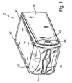
- FIG 1 A perspective view of a table top napkin dispenser is shown in figure 1 .
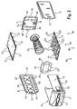
- the tabletop napkin dispenser 1 is made up of separately injection molded pieces that are able to be clipped or snap-fit together in order to form the tabletop napkin dispenser 1 shown in figure 1 . Some of these pieces can be seen in figure 2 , where there is shown a pre-assembly view of the table top napkin dispenser 1.
- the tabletop napkin dispenser 1 includes a base member 2, first, second, third and fourth sidewall members 3, 4, 5, 6, a front member 7 and a tray member 8.
- the base member 2 and the first, second, third and fourth sidewall members 3, 4, 5, 6 are clipped together in order to form an open ended oblong shaped box or chute 10 for housing a stack of napkins.
- the tabletop napkin dispenser 1 includes a drawer including a tray member 8 and a front member 7 that defines a dispensing opening 11 that are clipped together.
- the drawer 9 is movable between a rearward most position in which an open end of the cute 10 is closed by the front member 7 of the drawer 9 and a position in which the drawer 9 is dislocated from the chute 10 for ease of refilling the drawer 9 with napkins.
- the dispenser 1 further includes an elongate spring 15 that is connected to a front facing surface of the rear member 2 at one end and is connected to a rear facing surface of the platform 14 at its other end.
- the platform 14 serves to contact a rear facing surface of a stack of napkins disposed in the drawer 9.
- the spring 15 is in a more compressed configuration when the drawer 9 is full with napkins and in an extended configuration when the drawer 9 becomes depleted so that the platform 14 biases the stack of napkins to a position adjacent the dispensing opening 11 irrespective of the state of depletion of the stack of napkins.
- the first, second, third and fourth sidewall members 3, 4, 5, 6 extend between the rear member 2 and an open end of the chute 10.
- the first, second, third and fourth sidewall members 3, 4, 5, 6 include first and second sidewall members 3, 4 that have the same length as the third and fourth sidewall members 5, 6 in the rear to front direction, yet have a smaller width in a perpendicular direction to define smaller area rectangular shapes for the first and second sidewall members 3, 4 than the third and fourth sidewall members 5, 6.
- the rear member 2 provides a closed rear face to the open ended chute 10 having an open front end.
- the rear member 2 includes first and second tab-like projections 16, 17 that project from an outer periphery of the rear member 2 to engage in corresponding recesses 18 in a rear end of the first and second sidewall members 3, 4.
- the first and second tab-like projections 16, 17 project in a sideways direction.
- the rear member 2 further includes brackets 19 that overlap with a periphery of a rear end of the spring 15 in a rear to front direction in order to connect the spring 15 to the rear member 2. These brackets 19 are provided on a front facing surface of the rear member 2.
- the platform 14 includes depending members 20 that overlap with a periphery of the spring at the other end in a front to rear direction in order to connect the other end of the spring 15 to the underside of the platform 14.
- the larger area third and fourth sidewall members 5, 6 include resilient tab-like members 21 that project sideways from an outer periphery of the sidewall members 5, 6 in order to mount the third and fourth sidewall members 5, 6 to the first and second sidewall members 3, 4. More specifically, the projecting tab-like members 21 resiliently deflect in order to pass into corresponding openings in the first and second sidewall members 3, 4 and resiliently reform into the initial position in order to engage them.
- a rear end of the sidewall members 5, 6 include at least one (in the figure two) snap-fit projections 22 for clipping into counterpart structure in the rear wall member 2.
- the third and fourth sidewall members 5, 6 include the tab-like projections 21 on both sides thereof so that the third and fourth sidewall members 5, 6 are symmetrical about a central axis extending in a front to rear direction.
- the symmetrical constructions of the sidewall members 3, 4, 5, 6 allows the first and second sidewall members 3,4 to be interchanged in position with one another with respect to the rear member 2 and likewise the third and fourth sidewall members 5, 6 are interchangeable, yet the tab-like projections 21, the snap-fit projections 22 and the projecting tabs 16, 17 are still aligned with counterpart openings despite the interchange.
- the third and fourth sidewall members 5, 6 include a larger number (four shown) of outwardly extending projections 21 for securing them to the first and second sidewall members 3, 4 than the rear member 2 (which includes two outwardly extending projecting tabs 16, 17) for engaging the first and second sidewall members 3, 4.
- the chute 10 is thus formed by clipping together the rear member 2 and the first to fourth side wall members 3, 4, 5, 6 through protrusions engaging in recesses (which term includes slots), to thereby define a generally oblong shaped chute 10 having one open end.
- the third and fourth sidewall members 5, 6 include, on an interior side thereof, a plurality (shown four) of ribs 23 extending longitudinally from a rear end to a front end of the respective sidewall member 5, 6. These ribs protrude by a distance so as to support a tray defining wall of the tray member 8 of the drawer 9 in a low friction manner with respect to the fourth sidewall member 6 and to be able to project into a side face of the stack of napkins held in the drawer 9 to guide the stack of napkins.
- the ribs 23 project by a distance of about 7 mm.
- Also shown, but not identified by a reference numeral, are crossbars connecting the guide ribs 23 and diagonally oriented to structurally reinforce the ribs 23.
- the first and second sidewall members 3, 4 include structure to guide retraction and extension of the drawer 9.
- the first and second sidewall members 3, 4 include channels 24 in an interior facing surface for receiving opposed rails of the drawer 9.
- the channels 24 extend from a rear end to a front end of the sidewall members 3, 4.
- the channels 24 are defined between first and second ribs 26, 27 that extend in a front to rear direction and are spaced apart in a direction perpendicular thereto to provide a space or channel between them for receiving the guide rails 25.
- the first and second sidewall members 3, 4 are symmetrically formed with respect to a rear to front central axis passing through the chute 10 so that the first and second sidewall members 3, 4 include an upper and a lower drawer guiding channel 24.
- This enables the first and second sidewall members 3, 4 to be interchanged with one another for ease of the manufacturing process and also allows the drawer member 9 to be mounted in the orientation shown in figure 1 and also in an upside down orientation with respect to the chute 10.
- the third and fourth sidewall members 5, 6 are symmetrically formed with respect to the central axis so that they may also be interchanged with one another. In this way, one injection mold can be used for forming both the first and the second sidewall members 3, 4 and one injection mold can also be used for forming both the third and the fourth sidewall members 5, 6.
- the more centrally disposed drawer guiding rib 27 is a continuous (or at least more continuous) one, while the other guide rib 26 is discontinuous, formed into a plurality of rib portions spaced in the front to rear direction to provide a low friction interaction with the rails 25 for the rib 26 upon which the weight of the drawer 9 will rest.
- the discrete rib portions of the drawer guiding rib 26 are co-located with recesses for receiving tab-like projection 21 of the third and fourth sidewall members 5, 6, which provides clearance for moulding the corresponding recesses or slots in the first and second sidewall members 3, 4.
- the drawer 9, specifically the tray member 8 includes opposed guide rails 28 that project from an outside of the tray member 8.
- the guide rails 28 are provided to be accommodated in the opposed guide channels 24 of the first and second sidewall members 3, 4 in order to guide movement of the drawer 9 from a retracted to an extended position with respect to the chute 10.
- the guide rails 28 are defined by a pair of spaced ribs 29, 30 that extend longitudinally from a rear end to a front end of the drawer 9. These ribs 29, 30 define a relatively deep rail for insertion in the channel 24, while also reducing frictional contact with the first and second sidewall members 3, 4 as compared to a solidly defined rail 28.
- the first and second guide ribs 29, 30 are connected at the rear end and the front end to define a continuous loop.
- the upper guide rib 30 of the guide rail 28 is shaped with a concave depression to allow the drawer to be inserted in an upwardly angled state relative to a central axis passing in a rear to front direction of the chute 10 and, once partly inserted, lowered so that the drawer 9 moves along the axis to the retracted position.
- the tray member 8 comprises a base wall 31 and first and second upstanding sidewalls 32 as well as rear corner pieces 33.
- the stack of napkins is stored in the drawer 9 in an interior space defined by the base wall 31, the upstanding sidewalls 32 and the rear corner pieces 33.
- the rear corner pieces 33 frame an opening in the rear of the drawer member 8 through which the platform 14 passes as the drawer member 8 is mounted in the chute 10. With the drawer member 8 in the retracted position so that the chute 10 is closed by the front member 7, the platform 14 and spring 15 partially project through the opening framed by the rear corner pieces 33 to contact a rear face of the stack in the drawer 9. Part of the platform 14 and spring 15 will be disposed rearwardly of the rear opening in the drawer 9 in a space in the rear to front direction defined between the corner pieces 33 and the rear member 2.
- a front facing surface of the corner pieces 33 provides a surface against which a rear face of the stack of napkins seats when the drawer member 9 is filled with napkins.
- At least the base wall 31 and the upstanding sidewalls 32 of the tray member 8 are integrally injection molded.
- the rear wall pieces 33 can be separately injection molded and clipped in place to the sidewalls 32 or can be integrally injection molded with the rest of the tray member 8.
- the front of the drawer 9 is provided by a front member 7 that includes the dispensing opening 11.
- Sidewalls 32 of the tray member 8 include slits 34 extending therethrough and in communication with a front thereof.
- the front member 7 includes corresponding ribs to provide a mechanical fit between the front member 7 and the tray member 8.
- An adhesive may also be applied between the ribs and the slits 34 to ensure that the front member 7 is securely held to the tray member 8 of the drawer 9.
- Other attachment mechanisms are possible, including a snap-fit variation. The combination of mechanical fit and adhesive is used for the attachment between the front member 7 and the tray member 8 since this is a heavily handled part of the tabletop napkin dispenser 1 during use.
- the drawer 9 includes first and second tabs 12 disposed at a front end portion of the sidewalls 32 that can be deflected into the interior space defined by the tray member 8 to disengage projection tabs 36 from corresponding openings 13 in the first and second sidewall members 3, 4, thereby releasing the drawer 9 from a locked and retracted position for movement into a more extended or removed position relative to the chute 10.
- the first and second tabs 12 include resilient fingers 35 and projecting tabs 36 disposed at a distal end of the resilient fingers 35.
- the tab projections 36 are clip-on members with respect to the resilient fingers 35 in order to allow the base wall 31 and the sidewalls 32 and the resilient fingers 35 to be integrally injection molded to form the tray member 8.
- the guide rail 28 is also an integrally injection molded component of the tray member 8.
- the tray member 8 includes stop members 37 to prevent the resilient fingers 35 from extending too far inwardly in order to prevent the resilient fingers 35 from damaging the stack of napkins and also to prevent overstraining of the resilient fingers 35.
- the stop members 35 are provided by way of an obstructing surface in the path of the inward deflection of the resilient fingers 35.
- the stop members 37 are mounted to the sidewalls 32 of the tray member 8 at a distal end of the resilient fingers 35 and which include a projection disposed in the path of an inward deflection of the resilient fingers 35.
- the stop members 35 are formed in a ramped manner in that they taper to merge into the sidewalls 32 in a rearward direction and project further beyond the sidewalls 32 in a forward direction to guide the napkins toward the dispensing opening 11.
- the stop members 37 are separately formed from the tray member 9 and snap-fit to the sidewalls 37, which again allows the tray member 9 to be injection molded, while still allowing functional components such as the stop members 37 to be provided in a
- the front member 7 includes a transparent part 38 and an opaque part 39. These parts 38, 39 are attached together to provide a partially opaque and partially transparent front member 7.
- the transparent and opaque parts 38, 39 may be adhesively attached to one another.
- the transparent part 38 forms a lip 40 around a frame to the dispensing opening 11 formed by the opaque part 39.
- the transparent part 38 further fills-in cutout portions 41 defined in the opaque part 39 to form half-moon shaped transparent regions on either side of the dispensing opening 11 in order to allow the stack of napkins to be viewed through the front member 7.
- the front member is curved in profile so that the front member 7 extends from the dispensing opening 11 and curves in a front to rear direction so that a front end thickness of the stack of napkins in the drawer 9 can be viewed.
- the transparent part 38 includes this curved profile so that the end portion of the front of the stack in a stack height direction of front to rear direction can be viewed therethrough.
- the dispensing opening 11 is generally slot shaped with an enlarged portion in a central region of the slot.
- Transparent windows 50 on either side of the dispensing opening 11 provided by the transparent part 38 are elongate and share a longitudinal axis that extends parallel to a longitudinal axis of the slot-like dispensing opening. Since the front end portion of the stack can be viewed through the front member 7, it can be quickly and easily determined when the stack of napkins is in a depleted condition and also provides an intuitive feel to the dispensing operation.
- the third and fourth sidewall members 5, 6 are each formed of inner and outer plates 42, 43 that can be clipped together in order to define advertising material receiving space between them.
- the advertising material receiving space is substantially planar so that it is only large enough to receive sheet like material such as paper or thin cardboard.
- the inner plate 42 includes an outwardly protruding bump 44. This bump 44 holds open the advertising material receiving space, while also avoiding excessive feeding of the advertising material into the space.
- the inner and outer plates are separately injection molded parts, which allows the sidewall members 5, 6 and particularly the advertising material space defined by them to be formed in a low complexity manufacturing manner.
- the inner plate 45 includes a thumb sized cutout so that advertising material held in the space between the inner and outer plates 42, 43 can be retrieved easily from an inside of the chute 10.
- the inner and outer plates 42, 43 clip together by way of L-shaped brackets 46 and resilient fingers 47 so that the inner and outer plates 42, 43 can be brought together and partially overlapped in a direction normal to the plates 42, 43 and then moved longitudinally in a front to rear direction so that the L-shaped brackets 46 engage against engagement surfaces on the inner plate 42, whereat the resilient fingers 37 resiliently deflect into engagement with blocking surfaces on the outer plate 43 to prevent the outer plate 43 being moved in a rear to front direction to prevent the reverse operation to the just described mounting operation.
- the L-shaped brackets 46 are moved into engagement with further blocking surfaces on the inner plate 42 as a result of the relative movement between the inner and outer plates 42, 43 in the front to rear direction to block movement of the outer plate 43 relative to the inner plate 42 in a direction normal to the planes defined by the plates 42, 43.
- the combination of the resilient fingers 47 and the L-shaped brackets 46 and the blocking surfaces of the first and second plates 42, 43 lock the inner and outer plates 42, 43 together in a forward to rear direction, a rear to forward direction and in a direction perpendicular to the plane of the platers 42, 43.
- feet 46 that can be mounted (e.g. adhesively attached) to corresponding depressions in the third and fourth sidewall members 5, 6 and/or corresponding depressions 48 in the rear wall member 2.
- the dispenser 1 has depressions in both the third and fourth sidewall members 5, 6 and in the rear wall member 2 so that the tabletop napkin dispenser 1 can be used in a horizontally dispensing orientation, in which case they will be provided in the depressions 47, or in a vertically dispensing orientation, in which case the feet 46 will be provided in the depressions 48 of the rear wall member 2.
- the feet 46 serve to lift the napkin dispenser 1 from the tabletop surface and are made of a material such as rubber that is softer than the third and fourth sidewall members 5, 6 at the outer surfaces or the rear wall member 2 at the outer surface to provide a soft and scratch free interaction with the tabletop surface.
- a refilling operation for the napkin dispenser 1 and a dispensing operation for the napkin dispenser 1 will now be described with reference to figures 1 to 5 .
- the projections 36 of the tabs 12 on either side of the dispensing opening 11 can be pressed inwardly to resiliently deflect the resilient fingers 35 to take the tab projections 36 out of engagement with the openings 13 in the first and second sidewall members 3, 4.
- the drawer 9 for housing a stack of napkins is released from a locked and closed position with respect to the chute 10 of the napkin dispenser 1.
- the drawer 9 can be retracted with respect to the chute 10 by pulling the front member 7 forward while holding the projections 36 of the tabs 12 in the inwardly deflected, released position.
- the drawer 9 can be continued to be retracted until it is entirely removed from the confines of the chute 10 by sliding the guide rails 25 on either side of the drawer 9 along the guide channels 24 in the first and second sidewall members 3, 4. Once removed, the drawer 9 can be filled with napkins by aligning a stack height of the napkins with a rear to front direction of the drawer 9 so that a rear face of the stack of napkins is positioned against the rear wall pieces 33 of the drawer 9 and so that a front face of the stack of napkins is aligned with the front member 7 of the drawer 9.
- the rear of the drawer 9 is inserted into the open end of the chute 10 so that the guide rails 25 enter the guide channels 24.
- the guide rails 25 may include an angled portion at a rear end thereof in order to allow the drawer 9 to be angled with respect to a central axis passing in a front to rear direction of the chute 10.
- the drawer 9 is brought into an aligned position with the central axis and moved to a rearward position so that the front member 7 seats flush against a front end of the chute 10 to close the open end of the chute 10, whereat the projections 36 of the tabs 12 enter the openings 13 under resilient reformation of the resilient fingers 35 in order to lock the drawer member 9 in the retracted position.
- the opening in the rear end of the drawer 9 defined by the pieces 33 being arranged in a frame shape around the opening allows the platform 14 to pass at least partly through the rear opening in the drawer 9 to engage against a rear face of the stack.
- the platform 14 is moved to the rear end of the chute 10, which causes the spring 15 to become compressed.
- the stack of napkins is biased forwardly in the drawer 9 to a position adjacent the dispensing opening 11 when the drawer 9 is in the locked and retracted position.
- a sheet of advertising material can be fed between the inner and outer plates 42, 43 of the third and/or fourth sidewall members 5, 6.
- rubber feet can be mounted (e.g. stuck) in corresponding depressions 47 at the corners of outer surfaces of one of the third or fourth sidewall members 5, 6 or the rear wall member 2 depending upon whether horizontal or vertical dispensing is to be implemented.
- Napkins contained in the drawer 9 when the drawer 9 is in the locked and retracted position can be withdrawn through the dispensing opening 11 so that they come into contact with the transparent lip 40 as they are withdrawn.
- the lip forming piece 38 can be made of a different material such as one having a greater frictional interaction with the napkins, in order to ensure one at a time dispensing. As the stack depletes, there will come a point at which the platform or at least the rear extent of the stack of napkins can be viewed through the transparent windows 50 disposed on either side of the dispensing opening 11 at rearwardly curving parts of the front member 7 or where the rearward curve in combination with the transparent windows 50 allows an end portion, such as at least ten napkins, pressed against the front member 7 to be viewed.
- the platform 14 moves under the force of the biasing spring 15 toward the front member 7 to ensure that a napkin is disposed at the dispensing opening 11 for as long as napkins remain in the stack stored in the drawer 9.
- the stack of napkins will generally be interfolded so that as a front-most napkin is withdrawn through the dispensing opening 11 for use, the adjacent napkin in the stack is partly pulled through the dispensing opening 11 with it for grasping for the next use.
- FIG. 6 An embodiment of a tabletop dispenser according to the present invention is shown in figure 6.
- Figure 6 discloses a tabletop napkin dispenser 60, which can be seen in exploded view in figure 7 .
- the tabletop napkin dispenser comprises a rear wall member 61, first and second sidewall members 62, 63 and third and fourth sidewall members 64, 65.
- the rear wall member 61 and the first to fourth sidewall members 62-65 are separately injection molded pieces that are able to clip together in order to provide a chute 70 that is closed other than an open front end.
- a lid member 66 is pivotally attached to the chute 70 between an open position that gives access to the open front end of the chute 70 and a closed position that closes the front open end of the chute 70 so that napkins disposed within an interior spaced defined by the chute 70 are removed through the dispensing opening 69 of the lid member 66.
- the rear wall member 61 includes a flat inner surface 71 that will extend parallel to the plane of the tabletop when the dispenser stands on the rear wall member 61. Side parts curve upwards to define a curved rim 72 to long sides of the rear wall member 61. Further, upstanding inner side walls 73 extend normally to the flat surface 71 and define inner and outer surfaces that are parallel to the inner and outer surface of the inner and outer surfaces of the larger sidewall members 64, 65.
- First and second projecting tabs 74 extend from the edges of the smaller sides of the rear wall member 61.
- the first and second projecting tabs 74 engage with recesses disposed in a bottom of the first and second smaller sidewall members 62, 63, in order to secure the rear wall member 61 thereto.
- a projection 75 is also disposed on inner surface of the curved rims 72 between an outer surface of the upstanding sidewalls 72 and the long side edge of the rear wall member 61 at a location centrally disposed along the long side edge. These projections 75 engage with corresponding recesses 76 disposed at a rear end of the third and fourth sidewall members 64, 65.
- the third and fourth sidewall members 64, 65 include tabs 77 projecting from the smaller sides thereof to engage in corresponding recesses 78 provided in the smaller sidewall member 62, 63.
- the recesses 78 are defined by rails protruding normally from a general body of the first and second sidewall members 62, 63 inwardly that include slots or recesses 78 disposed therethrough. In this way, the chute 70 is formed from five separately injection molded pieces 61 to 65 that snap-fit together through protrusions engaging in recesses in a counterpart engagement member.
- a cavity is disposed in a space between inner surfaces of the third and fourth sidewall members 64, 65 and outer surfaces of the upstanding inner sidewalls 73 of the rear wall member 61 that is sheet or card shaped for receiving advertising material such as the cards 79 shown in figure 7 .
- the outer sidewall members 64, 65 are transparent so that advertising or other information on the cards 79 can be viewed through the third and fourth sidewall members 64, 65 from the outside of the napkin dispenser 60.
- the upstanding inner sidewalls 73 each include a central cutout that extends from a front end to a rear end and which is larger at the front end than at the rear end to define an upside down isosceles trapezoid shape to the cutout.
- the opposing upstanding inner sidewalls 73 of the rear member 61 are thus formed into two discrete portions separated by the cutout. This enables cards 79 to be disposed in the space between the outer surface of the upstanding inner sidewalls 73 and the third and fourth sidewall members 64, 65 that are of smaller height than accommodated by the space and which can still be retrieved from the inside of the dispenser through the cutouts. Yet further, the cutouts extend below a top edge of the curved rim 72, which provides clearance for injection molding the undercuts required to produce the projections 75 that engage with recesses 76 in the third and fourth sidewall members 64, 65.
- the platform 67 includes notches 80 at each corner end of the long sides of the platform 67 that extend through the thickness of the platform 67.
- the notches 80 receive guide ribs 81 that extend from a rear end to a front end of inner surfaces of the upstanding inner sidewalls 73 through which notches 80 and guide ribs 81, movement of the platform 67 from a retracted position adjacent the flat surface 71 of the rear wall member 61 to an extended position adjacent the dispensing opening 69 is guided.
- the platform 67 also includes a pair of notches 82 extending through a thickness of the platform 67 on each of the short sides of the platform 67.
- the pair of notches 82 are spaced apart from each other in a central position on the short sides so as to define a projecting portion 83 between them.
- the first and second sidewall members 62, 63 are each provided with guide ribs 84 extending from a rear end to adjacent a front end of the respective sidewall member 62, 63.
- the projecting portions 83 of the platform 67 are received between the guide ribs 84, while the guide ribs 84 are received in the notches 82. In this way, the platform 67 is guided by a guide mechanism provided on each of its four sides, namely by way of notch and rib mechanisms.
- the guide ribs 84 on each of the first and second sidewall members 62, 63 are connected at a front end by a cross member connecting rib 85.
- the cross member connecting rib 85 is positioned rearwardly in the rear to front direction of a front edge of the first and second sidewall members 62, 63 so that through openings 67 extending through a thickness of the first and second sidewall members 62, 63 are located above the cross member connecting rib 85.
- the lid member 66 includes depending resilient fingers 88 having tab-like projections 89 disposed at distal ends thereof.
- the tab-like projections 89 are sized to be received in the through openings 87 of the first and second sidewall members 62, 63 to lock a closed position of the lid member 66. From the outside of the napkin dispenser 60, a user can press the tab-like projections 89 inwardly through the openings 87 to resiliently deflect the resilient fingers 88, to thereby release the lid member 66 for opening.
- the tab-like projections 89 engage against the first and second sidewall members 62, 63 to deflect the resilient fingers 88 inwardly until the tab-like projections 89 align with the through openings 87 at which point the tab-like projections reengage with the through openings 87 under the bias of the resilient fingers 88 to lock the lid members 66.
- Stop members 86 project in a rear to front direction from a front facing surface of the cross member connecting rib 85 and are disposed in a path of inward deflection of the resilient fingers 88 to avoid over-inward deflection of the resilient fingers 88.
- a front facing edge of the stop members 86 is disposed below a bottom edge of the through openings 87.
- the stop members 86 define a stop position for inward deflection of the resilient fingers 88 such that the resilient fingers 88 cannot be moved inwardly to a position at or beyond the inward extension of the guide ribs 84 of the first and second sidewall members 62, 63 so that the resilient fingers 88 are prevented from coming into contact with, and thus scrunching, the napkins. That is, the inward extent of the guide ribs 84 defines the stack location in a long direction of the platform 67 and the stop members 86 are disposed outwardly of this inward extent to prevent the resilient fingers 88 coming into contact with the stack of napkins.
- a spring 68 is disposed between the flat surface 71 of the rear member 61 and a rear facing side of the platform 67.
- the rear facing side of the platform 67 includes brackets for securing an end of the spring 68.
- the other end of the spring freely rests against the flat surface 71 of the rear member 61 (although it could be secured thereto by brackets or the like at the cost of some manufacturing simplicity).
- the retracted position of the platform 67 is defined when a rear side of the platform 67 comes into contact with the flat surface 71 of the rear member 61.
- An extended position of the platform 67 is defined when a front facing side of the projecting portions 83 of the platform 67 comes into contact with a rear facing side of the cross member connecting rib 85.
- the spring 68 biases the platform 67 from the retracted position to the extended position so that the napkins are always disposed adjacent the dispensing opening 69 irrespective of the depletion state of the stack of napkins.
- the lid member 66 includes first and second pivot arms 90 at either end of the long side of the lid member 66.
- the first and second pivot arms 90 include pivot openings 91 therethrough at a distal end of the pivot arms 90 that receive pivot projections 92 disposed on an inner surface of the first and second sidewall members 62, 63, respectively.
- the first and second sidewall members 62, 63 each include first and second pivot projections 92 at a front end portion thereof and symmetrically disposed with respect to a rear to front axis passing centrally between the short sides of the first and second sidewall members 62, 63.
- the lid member 66 can be mounted to one side of the first and second side wall members 62, 63 or the other side of the first and second sidewall members 62, 63.
- first and second sidewall members 62, 63 can be identical pieces and interchanged with one another, to simplify the manufacturing process.
- the third and fourth sidewall members 64, 65 are formed from the same injection mold as are the first and second sidewall members 62, 63 and are interchangeable with one another in the napkin dispenser 60.
- the lid member 66 is a two-piece construction made from separate injection molded pieces 93, 94.
- the opaque piece 94 includes the pivot arm 90 and the resilient fingers and tab-like projections 88, 89.
- the transparent piece 93 provides a lip 97 of the dispensing opening 69 and also transparent windows 95, 96 disposed on either side of the dispensing opening 69 and extending along the dispensing opening 69 along a long side of the lip member 66 from substantially at one end to substantially at the other end.
- the lid member 66 includes a more flattened portion framing the dispensing opening 69 as provided by the opaque piece 94, while the transparent windows 95, 96 curve rearwardly from the more flattened portion so that a depth of the stack of napkins (such as at least 10 napkins) can be seen through the transparent windows 95, 96 so that a user can determine when the stack of napkins is reaching a depleted state.
- the transparent piece 93 and the opaque piece 94 include overlapping interfacing surfaces that are provided with an adhesive layer to adhere the first and second pieces 93, 94 together.
- the napkin dispenser 60 further includes four feet made of a relatively soft material as compared to the first and second sidewall members 62, 63 or the rear wall member 61 that are disposed in respective depressions at corner portions of an outer surface of a rear facing surface of the napkin dispenser 60.
- the soft feet 100 can be adhesively attached in the depressions.
- the depressions may be provided on an outer surface of a rear facing surface of the first and second sidewall members 62, 63.
- the feet 100 provide an interface between the napkin dispenser 60 and the table top surface and lift the remainder of the outer surface of the rear facing surface of the napkin dispenser 60 from the tabletop surface to avoid scratching of the table top surface.
- the feet 100 may be made of, for example, rubber.
- the embodiment of the tabletop napkin dispenser 60 of the present invention is stood on the feet 100 on the table top surface.
- the tab-like projections 89 protruding into the through openings 87 in the first and second sidewall members 62, 63 are pressed clear of the first and second sidewall members 62, 63 to allow the lid member 66 to be rotated about the pivots 91, 92 so that the lid 66 is moved into a position in which the body of the lid extends substantially parallel and outside of one of the third and fourth sidewall members 64, 65.
- the lid member 66 is thus moved into an open position exposing the open end of the chute 70.
- a stack of napkins can be placed with a rear surface of the stack laying on the front facing surface of the platform 67.
- the stack and the platform are pushed downwards to the position in which a rear facing surface of the platform 67 contacts the flat forward facing surface 71 of the rear wall member 61 such that that platform 67 is in its retracted position. Movement of the platform 67 is guided by notches 80, 82 and guide ribs 81, 84 on each of the four sides of the platform 67 and by the projecting portion 82 of the platform 67 being disposed between the pair of guide ribs 84 on the first and second sidewall members 62, 63, respectively.
- the lid member 66 With the platform 67 disposed in the retracted position and the stack of napkins thus clear of a forward facing edge of the chute 70, the lid member 66 can be rotated about the pivots 91, 92 into the closed position to close the chute 70.
- the tab-like projections 89 engage against the first and second sidewall members 62, 63 to inwardly deflect the resilient fingers 88 until the tab-like projections 89 align with the through openings 87 in the first and second sidewall members 82, 83. At which point the resilient fingers force the tab-like projections 89 outwardly into the through openings 87 to lock the closed position of the lid member 66.
- the napkins can be removed through the dispensing opening 69 so that they contact the lip 97 provided by the first piece 93 of the lid member 66.
- the lip 69 may be made of a high friction material with respect to the napkins than the other piece 94 of the lid member 66 so that the napkin adjacent in the stacking order to the napkin being dispensed is better gripped by the dispensing opening to ensure successful one at a time interfolded napkin dispensing operation.
- the stack reaches a depleted state, the user is given forewarning by viewing the bottom of the stack or a front facing surface of the platform 67 through the windows 95, 96, to garner an indication that the napkin dispenser 60 is to be refilled.
- the napkin dispenser 60 further includes provision for disposing advertising or other information cards in a sheet shaped cavity disposed between the inner surface and the third and fourth sidewall members 64, 65 and the outer surface of the inner sidewalls 73 of the rear member 61.
- the height of the information cards 79 in the rear to front direction can be designed with flexibility, since the inner sidewalls 73 include a centrally disposed cutout that extends from the front end to the rear end thereof.
- the cards 79 can include written information, graphics, advertising information or aesthetically pleasing designs that can be viewed through the transparent outer sidewall members 64, 65.
- rails 25 of the drawer 9 shown in figure 2 can be provided in split form in that it does not extend continuously from the rear end to the front end of the tray member 8. Instead, the rails 25 could be divided into two or more separate rails distributed from the front end to the rear end of the tray member 8.
- ribs 23 are disposed on inner surfaces of the third and fourth sidewall members 5, 6, this could be modified so that only the inner surface of the sidewall members 5, 6 in contact with the stack of napkins when the drawer member 9 is mounted in a predetermined orientation in the chute 10 is provided with the ribs 23. This modification would functionally achieve the stack guiding function, but at the expense of manufacturing flexibility since the third and fourth sidewall members 5, 6 would not then be interchangeable.
- the guide rails 25 of the drawer 9 are provided by upper and lower ribs connected at each end.
- a solid rail that does not include the space between the first and second ribs and is instead filled in with material could alternatively be provided, at the expense of the low friction arrangement of the first embodiment and weight and material use considerations.
- a rear opening is provided by four corner pieces 33.
- Each of these four corner pieces 33 is separated from one another.
- a continuous frame shape could, however, be provided, although this may make it less easy to injection mould the drawer 9.
- the front member 7 or the lid member 66 are made of first and second separate pieces. It is envisaged, however, that four separate pieces could be provided. A first opaque piece as shown in the figures, a second lip providing piece and third and fourth transparent window providing pieces. In this way, the transparent windows would not be connected to the transparent lip by connecting webs as shown in figures 4 and 8 .
Landscapes
- Health & Medical Sciences (AREA)
- Public Health (AREA)
- Absorbent Articles And Supports Therefor (AREA)
- Containers And Packaging Bodies Having A Special Means To Remove Contents (AREA)
- Packages (AREA)
- Closures For Containers (AREA)
- Blow-Moulding Or Thermoforming Of Plastics Or The Like (AREA)
- Packaging Of Annular Or Rod-Shaped Articles, Wearing Apparel, Cassettes, Or The Like (AREA)
- Stackable Containers (AREA)
- Details Of Rigid Or Semi-Rigid Containers (AREA)
Description
- The present invention is concerned with a tabletop napkin dispenser, which is a dispenser for dispensing napkins that is designed to placed on the top of a table or counter or the like so that a user can withdraw napkins from the confines of the dispenser in a one-at-a-time fashion through a dispensing opening. The napkin dispenser includes a housing defining a product reservoir for receiving a stack of napkins. The napkins are generally interfolded so that withdrawing one napkin causes the next napkin to be partly pulled through the dispensing opening.
- There is known from
WO 2006/132618 a tabletop napkin dispenser that is intended to be stood on a rear face so that a front face including a dispensing opening faces upwards. The dispenser has side faces connecting the front and rear faces of a height such that the dispenser is able to accommodate a stack of about 200 napkins. As such, the height dimension of the napkin dispenser is less than a length direction of a footprint of the dispenser. There is also known fromWO 2005/107548 a dispenser able to hold a stack of about 450 napkins, whereby the height dimension from a rear face to an opposing front face including the dispensing opening is greater than a length dimension of the front and rear faces. The dispenser of WO '548 is intended to be laid on its side, specifically on a side face of largest area so that, unlike the device of WO '618, it does not stand on its rear face. The dispenser of WO '618 dispenses vertically, while the dispenser of WO '548 dispenses horizontally. In the following, we will refer to these two types of dispenser as a vertically dispensing tabletop dispenser and a horizontally dispensing tabletop dispenser accordingly. - The vertically dispensing device of WO '618 is made of a base element forming the rear face, a sleeve element forming the side faces of the dispenser and a lid mounted to the sleeve by a hinge. The base element includes upstanding side wall members, two of which cooperate with the sleeve to define a paper thin cavity that is open at a top end for receipt of, e.g., advertising material. The sleeve is thus transparent so that the advertising material can be viewed through it. The other two upstanding side wall members form a catch mechanism with the lid for holding the lid in a closed position.
- The base element and the sleeve element clip together on all four sides at the base end of the sleeve. Manufacturing considerations mean that the base element and the sleeve are required to be fairly square, whereas a more rounded shape could be aesthetically preferable, it has been found.
- The lid of the vertically dispensing device of WO '618 is openable and closeable about the hinge. In the open position, a napkin reservoir is accessible for refilling. In the closed position of the lid, the refill access is substantially closed by the lid so that the napkins have to be removed through the dispensing opening defined in the lid. The lid is held in the closed position by resilient catch members extending upwardly from the upstanding side wall members of the base element to engage on corresponding catch members formed inside the lid. A platform fits in the space defined by the sleeve and the side wall members upon which the stack rests. The platform is biased by a spring to the dispensing opening.
- To release the catches, the side wall members of the base element have to be pushed inwardly through an archway provided in the sleeve member. This requires Further, when the platform is at an uppermost position adjacent the dispensing opening, which occurs when the stack is low or entirely used up, the platform tends, due to close tolerances, to obstruct inward depression of the upstanding side wall members and the associated catch members, it has been found. It is desirable to provide an easier to open lid member, once the user knows the knack of doing so.
- The upstanding side wall members partly defining the advertising cavity include a thumb sized cut out from an otherwise rectangular member to allow the advertising material to be removed and, perhaps, replaced. The advertising material is thus required to be of a specific size, encouraging the use of a template format for designing the advertising material. It has been found that a more flexible system could be desirable.
- In the horizontally dispensing napkin dispenser of WO '548, there is also provided a sleeve member that defines a housing of the dispenser and also defines an internal product reservoir. The sleeve member is clipped to a base member. The sleeve member, and thus an outer appearance of the dispenser, is restricted to being relatively square shaped because of manufacturing considerations, while it has been found that consumers may prefer a more rounded appearance.
- The sleeve member defines guide channels that receive guide rails of a drawer. The drawer is guided between a retracted and closed position with respect to the sleeve and an extended position for refilling the drawer with napkins. A front face of the drawer defines a front face of the dispenser and includes a dispensing opening. The drawer is held closed in the retracted position by a catch mechanism. The drawer defines a tray with upstanding side and rear walls for receiving the stack of napkins. A transverse panel translatably mounted in the drawer is provided to bias the stack toward the dispensing opening. It has been found that the biasing configuration disclosed in WO '548 can in some uses allow the napkins to fall away from the dispensing opening as the stack nears a fully depleted state. It has been found that a more consistent biasing configuration could be useful in some instances.
- The dispenser of WO '548 has been designed purely for horizontal dispensing. It has been found that a dispenser of this kind, with a drawer and a relatively large napkin capacity, that can also dispense vertically would be desirable.
- Objects of the various aspects of the present invention aim to overcome the above identified problems or resolve the above identified desirable features.
- In an aspect of the present invention, there is provided a tabletop napkin dispenser including a lid member and an open ended housing defining an interior space for housing a stack of napkins, wherein the lid member includes a dispensing opening, and wherein the lid member is moveable from an open position for providing access to refill napkins in the interior space and a closed position to close the open end of the housing, wherein the lid member includes at least one tab or resilient arm extending away from the lid member towards the housing and the other of lid member or the housing includes a through opening into which a projection of the tab or resilient arm resiliently snaps to hold the lid member in the closed position, wherein the projection can be pushed on from outside of the napkin dispenser and moved through the opening to resiliently deflect the tab interiorly to disengage the projection and the opening to allow the lid member to be opened.
- According to this aspect of the invention, the mechanism for unlocking the lid member is more intuitive and can involve less force than a mechanism described above with respect to the prior art in which a whole side wall has to be deflected, once the user knows the knack of operating the unlocking mechanism.
- The tab member is attached at one end to the lid member and projects freely therefrom and includes an arm portion in the direction of projection and a projection portion defining the projection for engaging the through opening at the distal end of the arm portion. This structure offers an easy to deflect configuration.
- In an embodiment, the napkin dispenser includes a platform upon which the stack is to seat that is reciprocal within the housing from a retracted position relative to the dispensing opening to an adjacent most position relative to the dispensing opening in a rear to front direction. In an embodiment, the napkin dispenser includes a biasing means, such as a spring, for biasing the platform from the retracted position to the adjacent most position.
- In an embodiment, the platform is arranged so that the tab deflects to disengage the projection from the opening in a way that is clear of the platform in the adjacent most position. This feature serves to ease unlocking of the lid member as compared to the prior art arrangement whereby the deflection portion is obstructed by the platform.
- The tab depends from the lid member and the opening is provided in the housing. In one embodiment, the through opening is located in the housing above the plane of the platform in the rear to front direction when the platform is in the adjacent most position.
- In one embodiment, the lid member is pivotably connected to the open ended housing and is rotatable about the pivot between the closed and open positions. In an embodiment, the tab or opposed such tabs are provided on the side of the lid member or housing at a central location perpendicular to the pivot axis. In an embodiment, there is first and second such tabs and through openings that are positioned on the housing or the lid member at opposite ends of a line extending from one side of the dispenser to the other in parallel with the pivot axis.
- Alternatively put, in one embodiment, the housing includes a rear face and four side faces, two larger than the other two to define an open ended oblong. In an embodiment, tabs or openings are provided on opposing smaller side faces. In one embodiment, the lid member is pivotally connected at each end to the opposing smaller faces. The pivotal connection is located at a corner portion of the smaller faces, while the through openings or tabs are located at a central region of the smaller faces.
- In one embodiment, the housing includes opposed sidewalls each defining a channel defined between first and second ribs extending in the rear to front direction. Opposed sides of the platform each include first and second projecting tabs that are guided by the ribs on the outside of the channel. This arrangement provides for stable guiding of the platform. The tabs are part of an outer perimeter shape of the platform. In an embodiment, the first and second tabs include protrusions that extend toward the guide ribs so as to reduce the contact area with the guide ribs to improve the feel of the movement of the platform.
- Put another way, the platform includes first and second notches extending through the thickness of the platform at each of opposed sides thereof for receiving first and second guide ribs of corresponding opposed side wall members, thereby guiding the movement of the platform. The first and second guide ribs extend from a rear end of the housing to a front end portion and define a channel between them. The platform may include opposed projecting portions received in the opposed channels of the side wall members for guiding movement of the platform from a retracted position to an extended position relatively adjacent the dispensing opening.
- In an embodiment, at least one of the channels are closed at a forward end by a cross bar extending between the first and second guide ribs and the platform includes at least one limiter tab (or the projecting portion) that is disposed inside the channel and which contacts the cross bar to limit the platform from moving any further in the rear to forward direction, thereby defining the adjacent most position of the platform. This way of limiting the movement of the platform is relatively easy to manufacture and provides a nicely integrated way of achieving the guide and limit functions for the movement of the platform. It is thus an independently applicable feature of the invention with respect to the tab and opening locking mechanism for the lid member. In an embodiment, the limiter tab is located at a rear side of the thickness of the platform so that the top of the platform extends above the cross bar in the rear to forward direction. In this way, sufficient space is provided in the rear to forward direction from the top of the guide rails in the side of the housing for accommodation of the opening or tab, while the platform is still positioned as close as possible to the dispensing opening.
- In an embodiment, the at least one tab is positioned in line with the guide channel in the forward to rear direction.
- In an embodiment, the crossbar includes an obstruction or stop member upstanding in the rear to forward direction that limits the degree of deflection of the tab provided with the lid member as the projection of the tab is moved out of the opening provided with the housing. This obstruction member prevents over deflection of the tab beyond its plastic deformation point. Further, the platform limiting and guiding functions and the tab protecting function are provided through a nicely integrated functional complex.
- The housing includes a stop member for limiting inward deflection of the tab or resilient arm to a stop position. In an embodiment, the stop position is located outwardly of an inward projecting extent of stack guiding ribs disposed adjacent the stop member so that the tab does not deflect so far inwardly as to scrunch, crush or otherwise contact the stack of napkins. Also, the stop member prevents over straining of the tab or resilient arm. In an embodiment, the stop member is positioned on a sidewall member of the housing. The stop member is positioned at a border of the opening. In an embodiment, the stop member projects so as to overlap with the opening. In an embodiment, the stop member is integrally moulded or clipped to a side wall member that it is associated with.
- The tab member is attached at one end to the lid member and projects freely therefrom and includes an arm portion in the direction of projection and a projection portion defining the projection for engaging the recess at the distal end of the arm portion. In an embodiment, the stop member is positioned to contact and obstruct movement of a distal end portion of the arm portion. In an embodiment, the stop member has an attached end and a free end, wherein the free end projects to overlap a path of inward deflection of the tab member. In an embodiment, the attached end of the stop member is located at a border of the through opening.
- In one embodiment, a plurality of such tab and through openings is provided.
- The dispenser of
figures 1 to 5 does not constitute an embodiment of the present invention. -
Figure 1 shows a table top dispenser for dispensing napkins that has a removable drawer for increased napkin capacity. The drawer is released by the pressing resilient tabs at either side of a dispensing opening. The table top dispenser is made up of four sidewall members and a rear member that clip together. The larger area sidewall members are made up of first and second sidewall plates, the outer of which is see-through so that advertising material disposed in the space between the inner and outer sidewall plates can be seen. The tabletop napkin dispenser includes a platform that is biased by a spring to urge a stack of napkins held in the drawer of the dispenser toward the dispensing opening and away from the base member. -
Figure 2 shows a napkin dispenser in which various components are shown before they have been assembled together. In particular, there is shown a drawer including a front member, first to fourth sidewall members, a base member, a platform and a spring for biasing the platform toward the dispenser opening. The first to fourth sidewall members and the base member clip together to define an open ended box (or chute) for receiving the drawer therein in a slideable manner that is movable between open and closed positions with respect to the open ended box. The spring or biasing member is attached at one end to a front facing surface of the base member and at the other end to a rear facing surface of the platform. -
Figure 3 shows the drawer in detail. The drawer includes a tray member for receiving a stack of napkins and a front member that attaches to the tray member for defining the dispensing opening. The tray member includes resilient tabs that engage with corresponding openings in the sidewall members when the drawer member is in the closed position and which can be depressed in order to release the drawer member from the open ended box to allow it to be retracted to a position for refilling. Walls of the tray member have mounted thereon respective stop members for preventing over inward depression of the resilient tabs. -
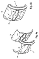
Figure 4 discloses a front member of the napkin dispenser in detail. The front member is made of two parts that clip together. A first part provides an opaque frame for the dispensing opening and the portions mounting to the drawer member, while a second part is transparent and defines lips of the dispensing opening as well as filling in side portions of the first part to provide an aesthetically pleasing transparent and opaque mix. -
Figure 5 shows a sidewall member of the napkin dispenser in detail. The napkin dispenser includes first, second, third and fourth sidewall members, two opposed of which define corresponding relatively small areas, and two opposed of which define relatively large areas.Figure 5 shows the larger area sidewall members in detail. The larger area sidewall member is made up of first and second plates that clip together to define an advertising material receiving space between them. The outer of the plates is transparent, while the inner of the plates is opaque so that the advertising material can be viewed through the transparent plate. Also shown is that the outer plates includes four depressions at each corner for receiving respective feet members to stand the napkin dispenser on and for providing a soft interface with the tabletop. -
Figure 6 discloses an embodiment of the present invention of a tabletop napkin dispenser of a kind in which a rear to front dimension or a stack height capacity dimension is smaller than a length and/or width dimension of the dispenser, which can be compared with the napkin dispenser offigures 1 to 5 wherein the rear to front dimension is greater than a length and width dimension of the napkin dispenser. The napkin dispenser offigure 6 is designed to be stood on a rear wall member so that a front wall member and its associated dispensing opening faces upwardly, to define a vertically dispensing dispenser. The napkin dispenser offigure 6 further includes four sidewall members connecting the rear wall member and the front wall member, wherein two opposed of the sidewall members are of a larger area than the other two opposed side wall members, so that the napkin defines a generally oblong shape. The front wall member is locked in a closed position with respect to a chute defined by the four sidewall members and a rear wall member and can be released to pivotally open with respect to the chute in order to allow refilling of a napkin reservoir defined by the interior space defined within the four sidewall members and the rear wall member. A platform is disposed within the interior space that is movable between a retracted position and an extended position and is biased by a biasing member to the extended position with respect to the dispensing opening so that the stack of napkins is always disposed adjacent the dispensing opening irrespective of the depletion state of the stack of napkins. -
Figure 7 provides an exploded view of various parts of the napkin dispenser offigure 6 . This figure shows that the four sidewall members, the rear wall member and the front wall member are separately injection molded pieces, as is the platform. A sheet-sized cavity is disposed between the larger of the sidewall members, which are transparent, and upstanding inner wall members extending normally to a general body of the rear wall member. A stack receiving interior space is defined within inner surfaces of the upstanding inner wall members of the rear wall member and inner surfaces of the inner sidewall members. The platform is received and guided within this space between the retracted and extended positions. Also shown infigure 7 are rectangular cards for disposition in the cavity defined in the space between the larger sidewall members and the inner upstanding sidewall members of the rear wall member. -
Figure 8 discloses a two-piece construction for the front or lid member of the tabletop napkin dispenser. An opaque piece includes pivot arms having respective openings therein for receiving pivot protrusions of the smaller sidewall members, to define a pivot axis about which the lid member will rotate between open and closed positions. The opaque piece also includes depending resilient fingers including tab-like protrusions for engagement in respective openings in the smaller sidewall members to allow the lid member to be locked in the closed position when the tab-like projections engage with the openings and to allow the lid member to be released from the locked position for pivoting to the open position when the tab-like projections are depressed by a user from the outside to deflect the resilient arms inwardly to disengage the tab-like projections from the openings. A transparent piece of the lid member defines a lip of the opening of the dispensing opening and also transparent outer portions disposed on either side of the dispensing opening and which extend from one end of the lid member to the other to provide transparent windows for viewing a depletion state of the napkins within the napkin dispenser. - A perspective view of a table top napkin dispenser is shown in
figure 1 . The tabletop napkin dispenser 1 is made up of separately injection molded pieces that are able to be clipped or snap-fit together in order to form the tabletop napkin dispenser 1 shown infigure 1 . Some of these pieces can be seen infigure 2 , where there is shown a pre-assembly view of the table top napkin dispenser 1. The tabletop napkin dispenser 1 includes abase member 2, first, second, third andfourth sidewall members tray member 8. - The
base member 2 and the first, second, third andfourth sidewall members chute 10 for housing a stack of napkins. The tabletop napkin dispenser 1 includes a drawer including atray member 8 and a front member 7 that defines a dispensingopening 11 that are clipped together. Thedrawer 9 is movable between a rearward most position in which an open end of the cute 10 is closed by the front member 7 of thedrawer 9 and a position in which thedrawer 9 is dislocated from thechute 10 for ease of refilling thedrawer 9 with napkins. - The dispenser 1 further includes an
elongate spring 15 that is connected to a front facing surface of therear member 2 at one end and is connected to a rear facing surface of theplatform 14 at its other end. Theplatform 14 serves to contact a rear facing surface of a stack of napkins disposed in thedrawer 9. Thespring 15 is in a more compressed configuration when thedrawer 9 is full with napkins and in an extended configuration when thedrawer 9 becomes depleted so that theplatform 14 biases the stack of napkins to a position adjacent the dispensingopening 11 irrespective of the state of depletion of the stack of napkins. - The first, second, third and
fourth sidewall members rear member 2 and an open end of thechute 10. The first, second, third andfourth sidewall members fourth sidewall members fourth sidewall members - The
rear member 2 provides a closed rear face to the open endedchute 10 having an open front end. Therear member 2 includes first and second tab-like projections rear member 2 to engage in correspondingrecesses 18 in a rear end of the first and second sidewall members 3, 4. The first and second tab-like projections like projections openings 18 on the first and second sidewall members 3, 4 are securely engaged to thereby mount therear member 2 and the first and second sidewall members 3, 4 together. - The
rear member 2 further includesbrackets 19 that overlap with a periphery of a rear end of thespring 15 in a rear to front direction in order to connect thespring 15 to therear member 2. Thesebrackets 19 are provided on a front facing surface of therear member 2. Theplatform 14 includes dependingmembers 20 that overlap with a periphery of the spring at the other end in a front to rear direction in order to connect the other end of thespring 15 to the underside of theplatform 14. - The larger area third and
fourth sidewall members like members 21 that project sideways from an outer periphery of thesidewall members fourth sidewall members like members 21 resiliently deflect in order to pass into corresponding openings in the first and second sidewall members 3, 4 and resiliently reform into the initial position in order to engage them. As can particularly be seen infigure 5b , a rear end of thesidewall members fit projections 22 for clipping into counterpart structure in therear wall member 2. Continuing to refer tofigure 5b , it can be seen that the third andfourth sidewall members like projections 21 on both sides thereof so that the third andfourth sidewall members sidewall members rear member 2 and likewise the third andfourth sidewall members like projections 21, the snap-fit projections 22 and the projectingtabs fourth sidewall members fourth sidewall members projections 21 for securing them to the first and second sidewall members 3, 4 than the rear member 2 (which includes two outwardly extending projectingtabs 16, 17) for engaging the first and second sidewall members 3, 4. - The
chute 10 is thus formed by clipping together therear member 2 and the first to fourthside wall members chute 10 having one open end. - The third and
fourth sidewall members ribs 23 extending longitudinally from a rear end to a front end of therespective sidewall member tray member 8 of thedrawer 9 in a low friction manner with respect to thefourth sidewall member 6 and to be able to project into a side face of the stack of napkins held in thedrawer 9 to guide the stack of napkins. In one example structure, theribs 23 project by a distance of about 7 mm. Also shown, but not identified by a reference numeral, are crossbars connecting theguide ribs 23 and diagonally oriented to structurally reinforce theribs 23. - The first and second sidewall members 3, 4 include structure to guide retraction and extension of the
drawer 9. In particular, the first and second sidewall members 3, 4 includechannels 24 in an interior facing surface for receiving opposed rails of thedrawer 9. Thechannels 24 extend from a rear end to a front end of the sidewall members 3, 4. Thechannels 24 are defined between first andsecond ribs - The first and second sidewall members 3, 4 are symmetrically formed with respect to a rear to front central axis passing through the
chute 10 so that the first and second sidewall members 3, 4 include an upper and a lowerdrawer guiding channel 24. This enables the first and second sidewall members 3, 4 to be interchanged with one another for ease of the manufacturing process and also allows thedrawer member 9 to be mounted in the orientation shown infigure 1 and also in an upside down orientation with respect to thechute 10. In fact, the third andfourth sidewall members fourth sidewall members - Turning back to the
drawer guiding channels 24 in the first and second sidewall members 3, 4, the more centrally disposeddrawer guiding rib 27 is a continuous (or at least more continuous) one, while theother guide rib 26 is discontinuous, formed into a plurality of rib portions spaced in the front to rear direction to provide a low friction interaction with therails 25 for therib 26 upon which the weight of thedrawer 9 will rest. The discrete rib portions of thedrawer guiding rib 26 are co-located with recesses for receiving tab-like projection 21 of the third andfourth sidewall members - Referring to
figures 3a and 3b , thedrawer 9, specifically thetray member 8, includes opposedguide rails 28 that project from an outside of thetray member 8. The guide rails 28 are provided to be accommodated in theopposed guide channels 24 of the first and second sidewall members 3, 4 in order to guide movement of thedrawer 9 from a retracted to an extended position with respect to thechute 10. The guide rails 28 are defined by a pair of spacedribs drawer 9. Theseribs channel 24, while also reducing frictional contact with the first and second sidewall members 3, 4 as compared to a solidly definedrail 28. The first andsecond guide ribs upper guide rib 30 of theguide rail 28 is shaped with a concave depression to allow the drawer to be inserted in an upwardly angled state relative to a central axis passing in a rear to front direction of thechute 10 and, once partly inserted, lowered so that thedrawer 9 moves along the axis to the retracted position. - The
tray member 8 comprises abase wall 31 and first and secondupstanding sidewalls 32 as well asrear corner pieces 33. The stack of napkins is stored in thedrawer 9 in an interior space defined by thebase wall 31, theupstanding sidewalls 32 and therear corner pieces 33. Therear corner pieces 33 frame an opening in the rear of thedrawer member 8 through which theplatform 14 passes as thedrawer member 8 is mounted in thechute 10. With thedrawer member 8 in the retracted position so that thechute 10 is closed by the front member 7, theplatform 14 andspring 15 partially project through the opening framed by therear corner pieces 33 to contact a rear face of the stack in thedrawer 9. Part of theplatform 14 andspring 15 will be disposed rearwardly of the rear opening in thedrawer 9 in a space in the rear to front direction defined between thecorner pieces 33 and therear member 2. - A front facing surface of the
corner pieces 33 provides a surface against which a rear face of the stack of napkins seats when thedrawer member 9 is filled with napkins. At least thebase wall 31 and theupstanding sidewalls 32 of thetray member 8 are integrally injection molded. Therear wall pieces 33 can be separately injection molded and clipped in place to thesidewalls 32 or can be integrally injection molded with the rest of thetray member 8. - The front of the
drawer 9 is provided by a front member 7 that includes the dispensingopening 11.Sidewalls 32 of thetray member 8 includeslits 34 extending therethrough and in communication with a front thereof. The front member 7 includes corresponding ribs to provide a mechanical fit between the front member 7 and thetray member 8. An adhesive may also be applied between the ribs and theslits 34 to ensure that the front member 7 is securely held to thetray member 8 of thedrawer 9. Other attachment mechanisms are possible, including a snap-fit variation. The combination of mechanical fit and adhesive is used for the attachment between the front member 7 and thetray member 8 since this is a heavily handled part of the tabletop napkin dispenser 1 during use. - The
drawer 9 includes first andsecond tabs 12 disposed at a front end portion of the sidewalls 32 that can be deflected into the interior space defined by thetray member 8 to disengageprojection tabs 36 from correspondingopenings 13 in the first and second sidewall members 3, 4, thereby releasing thedrawer 9 from a locked and retracted position for movement into a more extended or removed position relative to thechute 10. The first andsecond tabs 12 includeresilient fingers 35 and projectingtabs 36 disposed at a distal end of theresilient fingers 35. Thetab projections 36 are clip-on members with respect to theresilient fingers 35 in order to allow thebase wall 31 and thesidewalls 32 and theresilient fingers 35 to be integrally injection molded to form thetray member 8. Theguide rail 28 is also an integrally injection molded component of thetray member 8. - The
tray member 8 includes stopmembers 37 to prevent theresilient fingers 35 from extending too far inwardly in order to prevent theresilient fingers 35 from damaging the stack of napkins and also to prevent overstraining of theresilient fingers 35. Thestop members 35 are provided by way of an obstructing surface in the path of the inward deflection of theresilient fingers 35. Thestop members 37 are mounted to thesidewalls 32 of thetray member 8 at a distal end of theresilient fingers 35 and which include a projection disposed in the path of an inward deflection of theresilient fingers 35. Thestop members 35 are formed in a ramped manner in that they taper to merge into thesidewalls 32 in a rearward direction and project further beyond thesidewalls 32 in a forward direction to guide the napkins toward the dispensingopening 11. Thestop members 37 are separately formed from thetray member 9 and snap-fit to thesidewalls 37, which again allows thetray member 9 to be injection molded, while still allowing functional components such as thestop members 37 to be provided in a low complexity manufacturing manner. - Referring to
figures 4a and 4b , the front member 7 includes atransparent part 38 and anopaque part 39. Theseparts opaque parts transparent part 38 forms alip 40 around a frame to the dispensingopening 11 formed by theopaque part 39. Thetransparent part 38 further fills-incutout portions 41 defined in theopaque part 39 to form half-moon shaped transparent regions on either side of the dispensingopening 11 in order to allow the stack of napkins to be viewed through the front member 7. - In particular, the front member is curved in profile so that the front member 7 extends from the dispensing
opening 11 and curves in a front to rear direction so that a front end thickness of the stack of napkins in thedrawer 9 can be viewed. Thetransparent part 38 includes this curved profile so that the end portion of the front of the stack in a stack height direction of front to rear direction can be viewed therethrough. The dispensingopening 11 is generally slot shaped with an enlarged portion in a central region of the slot.Transparent windows 50 on either side of the dispensingopening 11 provided by thetransparent part 38 are elongate and share a longitudinal axis that extends parallel to a longitudinal axis of the slot-like dispensing opening. Since the front end portion of the stack can be viewed through the front member 7, it can be quickly and easily determined when the stack of napkins is in a depleted condition and also provides an intuitive feel to the dispensing operation. - Referring to
figures 5a and 5b , the third andfourth sidewall members outer plates outer plates inner plate 42 includes an outwardly protrudingbump 44. Thisbump 44 holds open the advertising material receiving space, while also avoiding excessive feeding of the advertising material into the space. The inner and outer plates are separately injection molded parts, which allows thesidewall members inner plate 45 includes a thumb sized cutout so that advertising material held in the space between the inner andouter plates chute 10. - The inner and
outer plates brackets 46 andresilient fingers 47 so that the inner andouter plates plates brackets 46 engage against engagement surfaces on theinner plate 42, whereat theresilient fingers 37 resiliently deflect into engagement with blocking surfaces on theouter plate 43 to prevent theouter plate 43 being moved in a rear to front direction to prevent the reverse operation to the just described mounting operation. The L-shapedbrackets 46 are moved into engagement with further blocking surfaces on theinner plate 42 as a result of the relative movement between the inner andouter plates outer plate 43 relative to theinner plate 42 in a direction normal to the planes defined by theplates resilient fingers 47 and the L-shapedbrackets 46 and the blocking surfaces of the first andsecond plates outer plates platers - Referring now to
figures 1 and2 , there is shownfeet 46 that can be mounted (e.g. adhesively attached) to corresponding depressions in the third andfourth sidewall members depressions 48 in therear wall member 2. The dispenser 1 has depressions in both the third andfourth sidewall members rear wall member 2 so that the tabletop napkin dispenser 1 can be used in a horizontally dispensing orientation, in which case they will be provided in thedepressions 47, or in a vertically dispensing orientation, in which case thefeet 46 will be provided in thedepressions 48 of therear wall member 2. Thefeet 46 serve to lift the napkin dispenser 1 from the tabletop surface and are made of a material such as rubber that is softer than the third andfourth sidewall members rear wall member 2 at the outer surface to provide a soft and scratch free interaction with the tabletop surface. - A refilling operation for the napkin dispenser 1 and a dispensing operation for the napkin dispenser 1 will now be described with reference to
figures 1 to 5 . - In order to refill the napkin dispenser 1, the
projections 36 of thetabs 12 on either side of the dispensingopening 11 can be pressed inwardly to resiliently deflect theresilient fingers 35 to take thetab projections 36 out of engagement with theopenings 13 in the first and second sidewall members 3, 4. In this way, thedrawer 9 for housing a stack of napkins is released from a locked and closed position with respect to thechute 10 of the napkin dispenser 1. Once unlocked, thedrawer 9 can be retracted with respect to thechute 10 by pulling the front member 7 forward while holding theprojections 36 of thetabs 12 in the inwardly deflected, released position. - The
drawer 9 can be continued to be retracted until it is entirely removed from the confines of thechute 10 by sliding the guide rails 25 on either side of thedrawer 9 along theguide channels 24 in the first and second sidewall members 3, 4. Once removed, thedrawer 9 can be filled with napkins by aligning a stack height of the napkins with a rear to front direction of thedrawer 9 so that a rear face of the stack of napkins is positioned against therear wall pieces 33 of thedrawer 9 and so that a front face of the stack of napkins is aligned with the front member 7 of thedrawer 9. - In order to reinsert the
drawer 9 into the open endedchute 10, the rear of thedrawer 9 is inserted into the open end of thechute 10 so that the guide rails 25 enter theguide channels 24. In order to ease this mounting process, the guide rails 25 may include an angled portion at a rear end thereof in order to allow thedrawer 9 to be angled with respect to a central axis passing in a front to rear direction of thechute 10. Once the guide rails 25 have begun running in theguide channels 24, thedrawer 9 is brought into an aligned position with the central axis and moved to a rearward position so that the front member 7 seats flush against a front end of thechute 10 to close the open end of thechute 10, whereat theprojections 36 of thetabs 12 enter theopenings 13 under resilient reformation of theresilient fingers 35 in order to lock thedrawer member 9 in the retracted position. - In passing the
drawer 9 through the open end of thechute 10, the opening in the rear end of thedrawer 9 defined by thepieces 33 being arranged in a frame shape around the opening allows theplatform 14 to pass at least partly through the rear opening in thedrawer 9 to engage against a rear face of the stack. As thedrawer 9 is moved into the retracted position, and with theplatform 14 pressed against a rear end of the stack, theplatform 14 is moved to the rear end of thechute 10, which causes thespring 15 to become compressed. As such, the stack of napkins is biased forwardly in thedrawer 9 to a position adjacent the dispensingopening 11 when thedrawer 9 is in the locked and retracted position. - If desired, a sheet of advertising material can be fed between the inner and
outer plates fourth sidewall members depressions 47 at the corners of outer surfaces of one of the third orfourth sidewall members rear wall member 2 depending upon whether horizontal or vertical dispensing is to be implemented. - Napkins contained in the
drawer 9 when thedrawer 9 is in the locked and retracted position can be withdrawn through the dispensingopening 11 so that they come into contact with thetransparent lip 40 as they are withdrawn. Thelip forming piece 38 can be made of a different material such as one having a greater frictional interaction with the napkins, in order to ensure one at a time dispensing. As the stack depletes, there will come a point at which the platform or at least the rear extent of the stack of napkins can be viewed through thetransparent windows 50 disposed on either side of the dispensingopening 11 at rearwardly curving parts of the front member 7 or where the rearward curve in combination with thetransparent windows 50 allows an end portion, such as at least ten napkins, pressed against the front member 7 to be viewed. - As the stack of napkins depletes, the
platform 14 moves under the force of the biasingspring 15 toward the front member 7 to ensure that a napkin is disposed at the dispensingopening 11 for as long as napkins remain in the stack stored in thedrawer 9. The stack of napkins will generally be interfolded so that as a front-most napkin is withdrawn through the dispensingopening 11 for use, the adjacent napkin in the stack is partly pulled through the dispensingopening 11 with it for grasping for the next use. - An embodiment of a tabletop dispenser according to the present invention is shown in
figure 6. Figure 6 discloses atabletop napkin dispenser 60, which can be seen in exploded view infigure 7 . - The tabletop napkin dispenser comprises a
rear wall member 61, first andsecond sidewall members fourth sidewall members rear wall member 61 and the first to fourth sidewall members 62-65 are separately injection molded pieces that are able to clip together in order to provide achute 70 that is closed other than an open front end. Alid member 66 is pivotally attached to thechute 70 between an open position that gives access to the open front end of thechute 70 and a closed position that closes the front open end of thechute 70 so that napkins disposed within an interior spaced defined by thechute 70 are removed through the dispensingopening 69 of thelid member 66. - The
rear wall member 61 includes a flatinner surface 71 that will extend parallel to the plane of the tabletop when the dispenser stands on therear wall member 61. Side parts curve upwards to define acurved rim 72 to long sides of therear wall member 61. Further, upstandinginner side walls 73 extend normally to theflat surface 71 and define inner and outer surfaces that are parallel to the inner and outer surface of the inner and outer surfaces of thelarger sidewall members - First and second projecting
tabs 74 extend from the edges of the smaller sides of therear wall member 61. The first and second projectingtabs 74 engage with recesses disposed in a bottom of the first and secondsmaller sidewall members rear wall member 61 thereto. Aprojection 75 is also disposed on inner surface of thecurved rims 72 between an outer surface of theupstanding sidewalls 72 and the long side edge of therear wall member 61 at a location centrally disposed along the long side edge. Theseprojections 75 engage withcorresponding recesses 76 disposed at a rear end of the third andfourth sidewall members fourth sidewall members tabs 77 projecting from the smaller sides thereof to engage in correspondingrecesses 78 provided in thesmaller sidewall member recesses 78 are defined by rails protruding normally from a general body of the first andsecond sidewall members chute 70 is formed from five separately injection moldedpieces 61 to 65 that snap-fit together through protrusions engaging in recesses in a counterpart engagement member. - A cavity is disposed in a space between inner surfaces of the third and
fourth sidewall members inner sidewalls 73 of therear wall member 61 that is sheet or card shaped for receiving advertising material such as thecards 79 shown infigure 7 . Theouter sidewall members cards 79 can be viewed through the third andfourth sidewall members napkin dispenser 60. The upstandinginner sidewalls 73 each include a central cutout that extends from a front end to a rear end and which is larger at the front end than at the rear end to define an upside down isosceles trapezoid shape to the cutout. - The opposing upstanding
inner sidewalls 73 of therear member 61 are thus formed into two discrete portions separated by the cutout. This enablescards 79 to be disposed in the space between the outer surface of the upstandinginner sidewalls 73 and the third andfourth sidewall members curved rim 72, which provides clearance for injection molding the undercuts required to produce theprojections 75 that engage withrecesses 76 in the third andfourth sidewall members - The
platform 67 includesnotches 80 at each corner end of the long sides of theplatform 67 that extend through the thickness of theplatform 67. Thenotches 80 receiveguide ribs 81 that extend from a rear end to a front end of inner surfaces of the upstandinginner sidewalls 73 through whichnotches 80 and guideribs 81, movement of theplatform 67 from a retracted position adjacent theflat surface 71 of therear wall member 61 to an extended position adjacent the dispensingopening 69 is guided. - The
platform 67 also includes a pair ofnotches 82 extending through a thickness of theplatform 67 on each of the short sides of theplatform 67. The pair ofnotches 82 are spaced apart from each other in a central position on the short sides so as to define a projectingportion 83 between them. The first andsecond sidewall members guide ribs 84 extending from a rear end to adjacent a front end of therespective sidewall member portions 83 of theplatform 67 are received between theguide ribs 84, while theguide ribs 84 are received in thenotches 82. In this way, theplatform 67 is guided by a guide mechanism provided on each of its four sides, namely by way of notch and rib mechanisms. - The
guide ribs 84 on each of the first andsecond sidewall members member connecting rib 85. The crossmember connecting rib 85 is positioned rearwardly in the rear to front direction of a front edge of the first andsecond sidewall members openings 67 extending through a thickness of the first andsecond sidewall members member connecting rib 85. - The
lid member 66 includes dependingresilient fingers 88 having tab-like projections 89 disposed at distal ends thereof. The tab-like projections 89 are sized to be received in the throughopenings 87 of the first andsecond sidewall members lid member 66. From the outside of thenapkin dispenser 60, a user can press the tab-like projections 89 inwardly through theopenings 87 to resiliently deflect theresilient fingers 88, to thereby release thelid member 66 for opening. When thelid member 66 is returned to the closed position, the tab-like projections 89 engage against the first andsecond sidewall members resilient fingers 88 inwardly until the tab-like projections 89 align with the throughopenings 87 at which point the tab-like projections reengage with the throughopenings 87 under the bias of theresilient fingers 88 to lock thelid members 66. - Stop members 86 project in a rear to front direction from a front facing surface of the cross
member connecting rib 85 and are disposed in a path of inward deflection of theresilient fingers 88 to avoid over-inward deflection of theresilient fingers 88. A front facing edge of the stop members 86 is disposed below a bottom edge of the throughopenings 87. The stop members 86 define a stop position for inward deflection of theresilient fingers 88 such that theresilient fingers 88 cannot be moved inwardly to a position at or beyond the inward extension of theguide ribs 84 of the first andsecond sidewall members resilient fingers 88 are prevented from coming into contact with, and thus scrunching, the napkins. That is, the inward extent of theguide ribs 84 defines the stack location in a long direction of theplatform 67 and the stop members 86 are disposed outwardly of this inward extent to prevent theresilient fingers 88 coming into contact with the stack of napkins. - A
spring 68 is disposed between theflat surface 71 of therear member 61 and a rear facing side of theplatform 67. The rear facing side of theplatform 67 includes brackets for securing an end of thespring 68. - The other end of the spring freely rests against the
flat surface 71 of the rear member 61 (although it could be secured thereto by brackets or the like at the cost of some manufacturing simplicity). The retracted position of theplatform 67 is defined when a rear side of theplatform 67 comes into contact with theflat surface 71 of therear member 61. An extended position of theplatform 67 is defined when a front facing side of the projectingportions 83 of theplatform 67 comes into contact with a rear facing side of the crossmember connecting rib 85. Thespring 68 biases theplatform 67 from the retracted position to the extended position so that the napkins are always disposed adjacent the dispensingopening 69 irrespective of the depletion state of the stack of napkins. - The
lid member 66 includes first andsecond pivot arms 90 at either end of the long side of thelid member 66. The first andsecond pivot arms 90 includepivot openings 91 therethrough at a distal end of thepivot arms 90 that receivepivot projections 92 disposed on an inner surface of the first andsecond sidewall members second sidewall members second pivot projections 92 at a front end portion thereof and symmetrically disposed with respect to a rear to front axis passing centrally between the short sides of the first andsecond sidewall members lid member 66 can be mounted to one side of the first and secondside wall members second sidewall members second sidewall members fourth sidewall members second sidewall members napkin dispenser 60. - Referring to
figures 8a and 8b , thelid member 66 is a two-piece construction made from separate injection moldedpieces transparent piece 93 and anopaque piece 94. Theopaque piece 94 includes thepivot arm 90 and the resilient fingers and tab-like projections transparent piece 93 provides alip 97 of the dispensingopening 69 and alsotransparent windows opening 69 and extending along the dispensingopening 69 along a long side of thelip member 66 from substantially at one end to substantially at the other end. Thelid member 66 includes a more flattened portion framing the dispensingopening 69 as provided by theopaque piece 94, while thetransparent windows transparent windows transparent piece 93 and theopaque piece 94 include overlapping interfacing surfaces that are provided with an adhesive layer to adhere the first andsecond pieces - The
napkin dispenser 60 further includes four feet made of a relatively soft material as compared to the first andsecond sidewall members rear wall member 61 that are disposed in respective depressions at corner portions of an outer surface of a rear facing surface of thenapkin dispenser 60. Thesoft feet 100 can be adhesively attached in the depressions. The depressions may be provided on an outer surface of a rear facing surface of the first andsecond sidewall members feet 100 provide an interface between thenapkin dispenser 60 and the table top surface and lift the remainder of the outer surface of the rear facing surface of thenapkin dispenser 60 from the tabletop surface to avoid scratching of the table top surface. Thefeet 100 may be made of, for example, rubber. - In use, the embodiment of the
tabletop napkin dispenser 60 of the present invention is stood on thefeet 100 on the table top surface. To fill thenapkin dispenser 60 with napkins, the tab-like projections 89 protruding into the throughopenings 87 in the first andsecond sidewall members second sidewall members lid member 66 to be rotated about thepivots lid 66 is moved into a position in which the body of the lid extends substantially parallel and outside of one of the third andfourth sidewall members lid member 66 is thus moved into an open position exposing the open end of thechute 70. - A stack of napkins can be placed with a rear surface of the stack laying on the front facing surface of the
platform 67. To close thelid member 66, the stack and the platform are pushed downwards to the position in which a rear facing surface of theplatform 67 contacts the flatforward facing surface 71 of therear wall member 61 such that thatplatform 67 is in its retracted position. Movement of theplatform 67 is guided bynotches ribs platform 67 and by the projectingportion 82 of theplatform 67 being disposed between the pair ofguide ribs 84 on the first andsecond sidewall members platform 67 disposed in the retracted position and the stack of napkins thus clear of a forward facing edge of thechute 70, thelid member 66 can be rotated about thepivots chute 70. - As the
lid member 66 is moved into the closed position, the tab-like projections 89 engage against the first andsecond sidewall members resilient fingers 88 until the tab-like projections 89 align with the throughopenings 87 in the first andsecond sidewall members like projections 89 outwardly into the throughopenings 87 to lock the closed position of thelid member 66. - The napkins can be removed through the dispensing
opening 69 so that they contact thelip 97 provided by thefirst piece 93 of thelid member 66. Thelip 69 may be made of a high friction material with respect to the napkins than theother piece 94 of thelid member 66 so that the napkin adjacent in the stacking order to the napkin being dispensed is better gripped by the dispensing opening to ensure successful one at a time interfolded napkin dispensing operation. As the stack reaches a depleted state, the user is given forewarning by viewing the bottom of the stack or a front facing surface of theplatform 67 through thewindows napkin dispenser 60 is to be refilled. - The
napkin dispenser 60 further includes provision for disposing advertising or other information cards in a sheet shaped cavity disposed between the inner surface and the third andfourth sidewall members inner sidewalls 73 of therear member 61. The height of theinformation cards 79 in the rear to front direction can be designed with flexibility, since theinner sidewalls 73 include a centrally disposed cutout that extends from the front end to the rear end thereof. Thecards 79 can include written information, graphics, advertising information or aesthetically pleasing designs that can be viewed through the transparentouter sidewall members - Various modifications can be made to the above-described dispensers.
- An example such modification is that the
rails 25 of thedrawer 9 shown infigure 2 can be provided in split form in that it does not extend continuously from the rear end to the front end of thetray member 8. Instead, therails 25 could be divided into two or more separate rails distributed from the front end to the rear end of thetray member 8. - Where
ribs 23 are disposed on inner surfaces of the third andfourth sidewall members sidewall members drawer member 9 is mounted in a predetermined orientation in thechute 10 is provided with theribs 23. This modification would functionally achieve the stack guiding function, but at the expense of manufacturing flexibility since the third andfourth sidewall members - The guide rails 25 of the
drawer 9 are provided by upper and lower ribs connected at each end. A solid rail that does not include the space between the first and second ribs and is instead filled in with material could alternatively be provided, at the expense of the low friction arrangement of the first embodiment and weight and material use considerations. - In the
drawer 9, a rear opening is provided by fourcorner pieces 33. Each of these fourcorner pieces 33 is separated from one another. A continuous frame shape could, however, be provided, although this may make it less easy to injection mould thedrawer 9. - The front member 7 or the
lid member 66 are made of first and second separate pieces. It is envisaged, however, that four separate pieces could be provided. A first opaque piece as shown in the figures, a second lip providing piece and third and fourth transparent window providing pieces. In this way, the transparent windows would not be connected to the transparent lip by connecting webs as shown infigures 4 and8 .
Claims (11)
- A tabletop napkin dispenser (60) including a front member (66) and an open ended housing (70) defining an interior space for housing a stack of napkins, wherein the front member includes a dispensing opening (69), and wherein the front member is moveable from an open position for providing access to refill napkins in the interior space and a closed position to close the open end of the housing; wherein the front member is provided by a lid member (66) pivotably connected to the open ended housing that is rotatable about the pivot (91, 92) between the closed and open positions, characterised in that:the front member includes at least one tab (88) and the housing includes a through opening (87) into which a projection (89) of the tab resiliently snaps to hold the front member in the closed position, wherein the projection can be pushed on from outside of the napkin dispenser and moved through the opening to resiliently deflect the tab interiorly to disengage the projection and the opening to allow the front member to be opened with respect to the housing,the napkin dispenser includes a stop member obstructing a path of inward deflection of the tab to define a stop position for limiting inward deflection of the tab,the tab member is attached at one end to the front member and includes an arm portion (88) freely projecting from the attached end, wherein a projection portion at a distal end of the arm defines the projection for engaging the opening.
- The napkin dispenser of claim 1, wherein the napkin dispenser includes a platform (67) upon which the stack is to seat that is reciprocal within the housing from a retracted position relative to the dispensing opening to an adjacent most position relative to the dispensing opening in a rear to front direction, wherein the napkin dispenser includes a biasing means (68), such as a spring, for biasing the platform from the retracted position to the adjacent most position.
- The napkin dispenser of claim 2, wherein the platform and the tab are arranged so that the tab deflects to disengage the projection from the opening in a way that is clear of the platform.
- The napkin dispenser of claim 2 or 3, wherein the through opening is located in the housing above the plane of the platform in the rear to front direction when the platform is in the adjacent most position.
- The napkin dispenser of claim 1, 2, 3 or 4, wherein the tab or opposed such tabs are provided on the side of the lid member or housing at a central location with respect to a direction extending perpendicular to the pivot axis.
- The napkin dispenser of claim 1, 2, 3, 4 or 5, wherein there is first and second such tabs (88) and through openings (87) that are positioned on the housing or the lid member at opposite ends of a line extending from one side of the dispenser to the other in parallel with the pivot axis.
- The napkin dispenser of any one of claims 1 to 6, wherein the napkin dispenser includes a platform (67) upon which the stack is to seat that is reciprocal within the housing from a retracted position relative to the dispensing opening to an adjacent most position relative to the dispensing opening in a rear to front direction, wherein the napkin dispenser includes a biasing means (68), such as a spring, for biasing the platform from the retracted position to the adjacent most position, and wherein the housing includes opposed sidewalls (62, 63) each defining a channel defined between first and second guide ribs (84) extending in the rear to front direction, wherein opposed sides of the platform each include first and second guide notches (82) that are guided by the guide ribs on the outside of the channel, wherein at least one of the channels is closed at a forward end by a cross bar (85) extending between the first and second guide ribs and the platform includes at least one limiter tab (83) that is disposed inside the channel and which contacts the cross bar to limit the platform from moving any further in the rear to forward direction, thereby defining the adjacent most position of the platform.
- The napkin dispenser of claim 7, wherein the crossbar includes the stop member (86) upstanding in the rear to forward direction that limits the degree of deflection of the tab provided with the front member as the projection of the tab is moved out of the opening provided with the housing.
- The napkin dispenser of any one of claims 1 to 8, wherein the stop position is located outwardly of an inward projecting extent of stack guiding structure (e.g. ribs) so that the tab does not deflect so far inwardly as to scrunch, crush or otherwise contact the stack of napkins or so that over straining of the tab is avoided to avoid plastic deformation of the tab.
- The napkin dispenser of any one of claims 1 to 9, comprising first and second opposed such tab (88) and through openings.
- The napkin dispenser of any one of the preceding claims, wherein the stop member projects so as to overlap with the through opening.
Priority Applications (2)
| Application Number | Priority Date | Filing Date | Title |
|---|---|---|---|
| PL14194471.0T PL2850984T3 (en) | 2011-10-31 | 2011-10-31 | Tabletop napkin dispenser |
| EP14194471.0A EP2850984B1 (en) | 2011-10-31 | 2011-10-31 | Tabletop napkin dispenser |
Applications Claiming Priority (3)
| Application Number | Priority Date | Filing Date | Title |
|---|---|---|---|
| EP11776447.2A EP2750570B1 (en) | 2011-10-31 | 2011-10-31 | Tabletop napkin dispenser |
| EP14194471.0A EP2850984B1 (en) | 2011-10-31 | 2011-10-31 | Tabletop napkin dispenser |
| PCT/EP2011/069116 WO2013064165A2 (en) | 2011-10-31 | 2011-10-31 | Tabletop napkin dispenser |
Related Parent Applications (2)
| Application Number | Title | Priority Date | Filing Date |
|---|---|---|---|
| EP11776447.2A Division EP2750570B1 (en) | 2011-10-31 | 2011-10-31 | Tabletop napkin dispenser |
| EP11776447.2A Division-Into EP2750570B1 (en) | 2011-10-31 | 2011-10-31 | Tabletop napkin dispenser |
Publications (3)
| Publication Number | Publication Date |
|---|---|
| EP2850984A2 EP2850984A2 (en) | 2015-03-25 |
| EP2850984A3 EP2850984A3 (en) | 2015-04-08 |
| EP2850984B1 true EP2850984B1 (en) | 2016-07-13 |
Family
ID=44897769
Family Applications (4)
| Application Number | Title | Priority Date | Filing Date |
|---|---|---|---|
| EP14194471.0A Active EP2850984B1 (en) | 2011-10-31 | 2011-10-31 | Tabletop napkin dispenser |
| EP14194472.8A Not-in-force EP2850985B1 (en) | 2011-10-31 | 2011-10-31 | Tabletop napkin dispenser |
| EP14194473.6A Withdrawn EP2850986A3 (en) | 2011-10-31 | 2011-10-31 | Tabletop napkin dispenser |
| EP11776447.2A Active EP2750570B1 (en) | 2011-10-31 | 2011-10-31 | Tabletop napkin dispenser |
Family Applications After (3)
| Application Number | Title | Priority Date | Filing Date |
|---|---|---|---|
| EP14194472.8A Not-in-force EP2850985B1 (en) | 2011-10-31 | 2011-10-31 | Tabletop napkin dispenser |
| EP14194473.6A Withdrawn EP2850986A3 (en) | 2011-10-31 | 2011-10-31 | Tabletop napkin dispenser |
| EP11776447.2A Active EP2750570B1 (en) | 2011-10-31 | 2011-10-31 | Tabletop napkin dispenser |
Country Status (14)
| Country | Link |
|---|---|
| US (2) | US9622627B2 (en) |
| EP (4) | EP2850984B1 (en) |
| CN (1) | CN103930012B (en) |
| AR (1) | AR088508A1 (en) |
| AU (2) | AU2011380282B2 (en) |
| BR (1) | BR112014010415B1 (en) |
| CA (2) | CA2855907C (en) |
| ES (1) | ES2584434T3 (en) |
| HU (1) | HUE029011T2 (en) |
| MX (1) | MX345573B (en) |
| PL (1) | PL2850984T3 (en) |
| UA (1) | UA110737C2 (en) |
| WO (1) | WO2013064165A2 (en) |
| ZA (1) | ZA201402616B (en) |
Families Citing this family (34)
| Publication number | Priority date | Publication date | Assignee | Title |
|---|---|---|---|---|
| WO2013064165A2 (en) * | 2011-10-31 | 2013-05-10 | Sca Hygiene Products Ab | Tabletop napkin dispenser |
| GB201205243D0 (en) | 2012-03-26 | 2012-05-09 | Kraft Foods R & D Inc | Packaging and method of opening |
| GB2511559B (en) | 2013-03-07 | 2018-11-14 | Mondelez Uk R&D Ltd | Improved Packaging and Method of Forming Packaging |
| GB2511560B (en) | 2013-03-07 | 2018-11-14 | Mondelez Uk R&D Ltd | Improved Packaging and Method of Forming Packaging |
| US9230388B2 (en) * | 2013-03-14 | 2016-01-05 | Nice-Pak Products, Inc. | Flow wrap holder |
| MX376716B (en) | 2013-12-09 | 2025-03-07 | Essity Hygiene & Health Ab | DISPENSER FOR INTERFOLDED NAPKINS. |
| CA2933280C (en) * | 2013-12-09 | 2022-06-21 | Sca Hygiene Products Ab | Dispenser for interfolded napkins |
| WO2016029964A1 (en) | 2014-08-29 | 2016-03-03 | Sca Hygiene Products Ab | Dispenser for interfolded napkins |
| GB201419490D0 (en) * | 2014-10-31 | 2014-12-17 | Fastrak Retail Uk Ltd | Ticket dispenser |
| US9629509B1 (en) | 2015-06-15 | 2017-04-25 | Dispensing Dynamics International | Wet wipe dispenser |
| WO2017023648A1 (en) * | 2015-08-05 | 2017-02-09 | Wausau Paper Towel & Tissue, Llc | Interfolded sheet dispenser |
| WO2017151088A1 (en) * | 2016-02-29 | 2017-09-08 | Kimberly-Clark Worldwide, Inc. | Dispensing system |
| RU2679183C1 (en) * | 2016-04-15 | 2019-02-06 | Огузхан Пластик Ве Калип Санайи Лимитед Ширкети | Paper napkin dispenser |
| TR201611193A1 (en) * | 2016-08-10 | 2018-02-21 | Eczacibasi Tueketim Ueruenleri Sanayi Ve Ticaret Anonim Sirketi | A DISPENSER FOR PAPER PRODUCTS |
| CN110167407B (en) * | 2017-01-09 | 2021-11-19 | 易希提卫生与保健公司 | Dispenser for dispensing sheet products |
| MX2019008216A (en) | 2017-01-09 | 2019-09-13 | Essity Hygiene & Health Ab | Dispenser for sheet products and operating method. |
| ES2973791T3 (en) | 2017-01-09 | 2024-06-24 | Essity Hygiene & Health Ab | Dispenser for sheet products and method of operation |
| USD836939S1 (en) | 2017-05-05 | 2019-01-01 | Cascades Canada Ulc | Dispenser |
| USD836938S1 (en) | 2017-05-05 | 2019-01-01 | Cascades Canada Ulc | Dispenser |
| EP3434163A1 (en) * | 2017-07-24 | 2019-01-30 | Carind S.r.l. | Serviette holder |
| USD855414S1 (en) | 2017-10-02 | 2019-08-06 | Gpcp Ip Holdings Llc | Napkin dispenser |
| USD855413S1 (en) | 2017-10-02 | 2019-08-06 | Gpcp Ip Holdings Llc | Napkin dispenser |
| CA179936S (en) | 2018-02-23 | 2020-03-05 | Cascades Canada Ulc | Dispenser |
| AU2018414440B2 (en) * | 2018-03-19 | 2021-05-06 | Essity Hygiene And Health Aktiebolag | Dispenser for sheet products, particularly napkins |
| CN112617646A (en) * | 2018-10-27 | 2021-04-09 | 张雨龙 | Tissue box capable of being conveniently extracted from lower part and using method |
| US10980377B1 (en) * | 2019-12-18 | 2021-04-20 | Essity Hygiene And Health Aktiebolag | Apparatus and methods for paper dispensing |
| US11116365B2 (en) | 2019-12-18 | 2021-09-14 | Essity Hygiene And Health Aktiebolag | Horizontally oriented paper product dispenser and related methods |
| US11498747B2 (en) * | 2020-01-08 | 2022-11-15 | Bobrick Washroom Equipment, Inc. | Liner dispenser |
| JP7465692B2 (en) * | 2020-03-23 | 2024-04-11 | 大王製紙株式会社 | Sheet Dispenser |
| EP4196075A1 (en) | 2020-08-12 | 2023-06-21 | CVS Pharmacy, Inc. | Modular dispenser for multiple objects |
| US12290213B2 (en) * | 2021-07-03 | 2025-05-06 | Elizabeth Raddatz | Towel dispenser |
| EP4373370B1 (en) * | 2021-07-19 | 2025-06-18 | Essity Hygiene and Health Aktiebolag | Dispenser for dispensing sheet material |
| CN117677327B (en) * | 2021-07-19 | 2026-04-17 | 爱适瑞卫生健康产品有限公司 | Desktop folding sheet dispenser |
| CN121816203A (en) * | 2023-09-12 | 2026-04-07 | 凡尔克斯医药系统公司 | System and method for peeling off the lid of a container for discarding pharmaceutical materials under aseptic conditions. |
Family Cites Families (32)
| Publication number | Priority date | Publication date | Assignee | Title |
|---|---|---|---|---|
| US1257413A (en) | 1917-04-12 | 1918-02-26 | Thomas Sloper | Pneumatic cushioning device for aircraft. |
| US2081564A (en) * | 1936-09-11 | 1937-05-25 | Marathon Paper Mills Co | Dispenser for folded sheets |
| US2253742A (en) * | 1940-05-08 | 1941-08-26 | Crown Zellerbach Corp | Dispenser for interfolded paper |
| US4118085A (en) * | 1977-06-13 | 1978-10-03 | The Steel City Corporation | Wall mounted tool cabinet |
| US4311252A (en) * | 1979-07-11 | 1982-01-19 | Griffith-Hope Company | Napkin dispenser |
| US4953747A (en) * | 1988-04-07 | 1990-09-04 | Wenkman Gregory J | Table model napkin dispenser |
| US5076466A (en) * | 1991-03-12 | 1991-12-31 | James River Ii, Inc. | Folded sheet product dispenser with anti-overfill mechanism |
| US5131561A (en) * | 1991-04-30 | 1992-07-21 | Wisconsin Tissue Mills Inc. | Universal napkin dispenser with interchangeable face plates |
| US5638962A (en) * | 1996-05-13 | 1997-06-17 | Engineered Data Products, Inc. | Tape cartridge storage assembly having retention tabs mounted to compartment divider walls |
| EP0879575B1 (en) * | 1997-05-23 | 2002-08-07 | The Procter & Gamble Company | Folding and stacking configuration for wet wipes having improved dispensation and single wet wipe separation from the stack |
| SE0101174L (en) * | 2001-04-02 | 2002-02-19 | Saab Ab | Method and signal transmitters for noise modulated remote measurement and group antenna systems including signal transmitters |
| US6824007B2 (en) * | 2001-07-25 | 2004-11-30 | Fort James Corporation | Curl limiting napkin dispenser |
| FR2830001B1 (en) * | 2001-09-25 | 2003-11-07 | Georgia Pacific France | MODULAR DISTRIBULAR |
| CN2546386Y (en) * | 2002-06-21 | 2003-04-23 | 肖代先 | Overlying paper napkin |
| US20040178648A1 (en) * | 2003-03-13 | 2004-09-16 | Moses Joel V. | Shopping bag handle |
| US7048143B2 (en) * | 2003-04-16 | 2006-05-23 | Kimberly-Clark Worldwide, Inc. | Container and cartridge for dispensing paper products |
| SE525145C2 (en) * | 2003-05-05 | 2004-12-07 | Sca Hygiene Prod Ab | Pile of folded material sheets and method of making them |
| US7204390B2 (en) | 2003-05-05 | 2007-04-17 | Sca Hygiene Products Ab | Stack of interfolded material sheets and method for its production |
| EP1693304B1 (en) * | 2003-09-04 | 2008-05-14 | Talleres Industriales Hiva S.A. | Dismantlable, returnable box |
| CN101186075B (en) * | 2004-01-20 | 2011-06-08 | 湖南邱则有专利战略策划有限公司 | Mould shell component shaping mould |
| US6981610B2 (en) * | 2004-03-10 | 2006-01-03 | Traex Company | Dispenser for a paper product |
| EP1742556A1 (en) * | 2004-05-07 | 2007-01-17 | Sca Hygiene Products Ab | Apparatus for serially dispensing folded sheet products |
| WO2005107548A1 (en) | 2004-05-07 | 2005-11-17 | Sca Hygiene Products Ab | Apparatus for serially dispensing folded sheet products and a method for manufacturing said apparatus |
| US20060273100A1 (en) * | 2004-10-25 | 2006-12-07 | Cittadino Antonio M | Tabletop napkin dispenser with display window for promotional material |
| US20060086748A1 (en) * | 2004-10-25 | 2006-04-27 | Fort James Corporation | Tabletop napkin dispenser |
| US7568593B2 (en) * | 2004-11-15 | 2009-08-04 | Georgia-Pacific Consumer Products Lp | High capacity napkin dispenser |
| HUE029905T2 (en) * | 2005-06-03 | 2017-04-28 | Sca Tissue North America Llc | Table top folded sheet dispenser |
| US7721913B2 (en) * | 2006-10-05 | 2010-05-25 | 3M Innovative Properties Company | Dispenser for repositionable notes |
| JP5143611B2 (en) * | 2008-03-31 | 2013-02-13 | ユニ・チャーム株式会社 | Sheet stack and sheet storage device |
| EP2765892B1 (en) * | 2011-10-13 | 2019-04-17 | San Jamar, Inc. | Napkin dispenser |
| WO2013064165A2 (en) * | 2011-10-31 | 2013-05-10 | Sca Hygiene Products Ab | Tabletop napkin dispenser |
| US20150031257A1 (en) * | 2011-12-22 | 2015-01-29 | Teijin Limited | Random Mat and Fiber-Reinforced Composite Material |
-
2011
- 2011-10-31 WO PCT/EP2011/069116 patent/WO2013064165A2/en not_active Ceased
- 2011-10-31 EP EP14194471.0A patent/EP2850984B1/en active Active
- 2011-10-31 CA CA2855907A patent/CA2855907C/en active Active
- 2011-10-31 EP EP14194472.8A patent/EP2850985B1/en not_active Not-in-force
- 2011-10-31 EP EP14194473.6A patent/EP2850986A3/en not_active Withdrawn
- 2011-10-31 CA CA3000707A patent/CA3000707C/en active Active
- 2011-10-31 ES ES14194471.0T patent/ES2584434T3/en active Active
- 2011-10-31 CN CN201180074619.1A patent/CN103930012B/en active Active
- 2011-10-31 MX MX2014005129A patent/MX345573B/en active IP Right Grant
- 2011-10-31 US US14/355,039 patent/US9622627B2/en active Active
- 2011-10-31 EP EP11776447.2A patent/EP2750570B1/en active Active
- 2011-10-31 BR BR112014010415-8A patent/BR112014010415B1/en active IP Right Grant
- 2011-10-31 HU HUE14194471A patent/HUE029011T2/en unknown
- 2011-10-31 PL PL14194471.0T patent/PL2850984T3/en unknown
- 2011-10-31 UA UAA201405942A patent/UA110737C2/en unknown
- 2011-10-31 AU AU2011380282A patent/AU2011380282B2/en active Active
-
2012
- 2012-10-24 AR ARP120103973A patent/AR088508A1/en not_active Application Discontinuation
-
2014
- 2014-04-10 ZA ZA2014/02616A patent/ZA201402616B/en unknown
- 2014-04-29 US US14/264,562 patent/US9901222B2/en active Active
-
2016
- 2016-06-09 AU AU2016203879A patent/AU2016203879B2/en active Active
Also Published As
Similar Documents
| Publication | Publication Date | Title |
|---|---|---|
| AU2016203879B2 (en) | Tabletop napkin dispenser | |
| AU2012389291B2 (en) | Dispenser for sheet products | |
| AU2006332671B2 (en) | Paper towel cabinet with paper towel support bar | |
| CN105769027B (en) | Table top napkin dispenser | |
| CN111698933B (en) | Dispensers for sheet products, especially napkins | |
| RU2574964C2 (en) | Table dispenser of napkins | |
| EP1847476B1 (en) | Sheet-like article storage container | |
| HK40037084A (en) | Dispenser for sheet products, particularly napkins | |
| HK1235643A1 (en) | Dispenser for interfolded napkins |
Legal Events
| Date | Code | Title | Description |
|---|---|---|---|
| PUAL | Search report despatched |
Free format text: ORIGINAL CODE: 0009013 |
|
| PUAI | Public reference made under article 153(3) epc to a published international application that has entered the european phase |
Free format text: ORIGINAL CODE: 0009012 |
|
| 17P | Request for examination filed |
Effective date: 20141124 |
|
| AC | Divisional application: reference to earlier application |
Ref document number: 2750570 Country of ref document: EP Kind code of ref document: P |
|
| AK | Designated contracting states |
Kind code of ref document: A2 Designated state(s): AL AT BE BG CH CY CZ DE DK EE ES FI FR GB GR HR HU IE IS IT LI LT LU LV MC MK MT NL NO PL PT RO RS SE SI SK SM TR |
|
| AX | Request for extension of the european patent |
Extension state: BA ME |
|
| AK | Designated contracting states |
Kind code of ref document: A3 Designated state(s): AL AT BE BG CH CY CZ DE DK EE ES FI FR GB GR HR HU IE IS IT LI LT LU LV MC MK MT NL NO PL PT RO RS SE SI SK SM TR |
|
| AX | Request for extension of the european patent |
Extension state: BA ME |
|
| RIC1 | Information provided on ipc code assigned before grant |
Ipc: B65D 83/08 20060101ALI20150302BHEP Ipc: B65D 6/00 20060101ALI20150302BHEP Ipc: A47K 10/42 20060101AFI20150302BHEP Ipc: B65D 6/24 20060101ALI20150302BHEP |
|
| RIN1 | Information on inventor provided before grant (corrected) |
Inventor name: WILSON, RODNEY Inventor name: SIEBEL, JUSTIN Inventor name: GONZALES, LEO |
|
| R17P | Request for examination filed (corrected) |
Effective date: 20150427 |
|
| RBV | Designated contracting states (corrected) |
Designated state(s): AL AT BE BG CH CY CZ DE DK EE ES FI FR GB GR HR HU IE IS IT LI LT LU LV MC MK MT NL NO PL PT RO RS SE SI SK SM TR |
|
| GRAP | Despatch of communication of intention to grant a patent |
Free format text: ORIGINAL CODE: EPIDOSNIGR1 |
|
| RIC1 | Information provided on ipc code assigned before grant |
Ipc: B65D 6/24 20060101ALI20160118BHEP Ipc: A47K 10/42 20060101AFI20160118BHEP Ipc: B65D 83/08 20060101ALI20160118BHEP Ipc: B65D 6/00 20060101ALI20160118BHEP |
|
| INTG | Intention to grant announced |
Effective date: 20160203 |
|
| GRAS | Grant fee paid |
Free format text: ORIGINAL CODE: EPIDOSNIGR3 |
|
| GRAA | (expected) grant |
Free format text: ORIGINAL CODE: 0009210 |
|
| AC | Divisional application: reference to earlier application |
Ref document number: 2750570 Country of ref document: EP Kind code of ref document: P |
|
| AK | Designated contracting states |
Kind code of ref document: B1 Designated state(s): AL AT BE BG CH CY CZ DE DK EE ES FI FR GB GR HR HU IE IS IT LI LT LU LV MC MK MT NL NO PL PT RO RS SE SI SK SM TR |
|
| REG | Reference to a national code |
Ref country code: GB Ref legal event code: FG4D |
|
| REG | Reference to a national code |
Ref country code: AT Ref legal event code: REF Ref document number: 811586 Country of ref document: AT Kind code of ref document: T Effective date: 20160715 Ref country code: CH Ref legal event code: EP |
|
| REG | Reference to a national code |
Ref country code: IE Ref legal event code: FG4D |
|
| REG | Reference to a national code |
Ref country code: DE Ref legal event code: R096 Ref document number: 602011028250 Country of ref document: DE |
|
| REG | Reference to a national code |
Ref country code: ES Ref legal event code: FG2A Ref document number: 2584434 Country of ref document: ES Kind code of ref document: T3 Effective date: 20160927 |
|
| REG | Reference to a national code |
Ref country code: NL Ref legal event code: FP |
|
| REG | Reference to a national code |
Ref country code: SE Ref legal event code: TRGR |
|
| REG | Reference to a national code |
Ref country code: FR Ref legal event code: PLFP Year of fee payment: 6 |
|
| REG | Reference to a national code |
Ref country code: LT Ref legal event code: MG4D |
|
| REG | Reference to a national code |
Ref country code: AT Ref legal event code: MK05 Ref document number: 811586 Country of ref document: AT Kind code of ref document: T Effective date: 20160713 |
|
| REG | Reference to a national code |
Ref country code: HU Ref legal event code: AG4A Ref document number: E029011 Country of ref document: HU |
|
| PG25 | Lapsed in a contracting state [announced via postgrant information from national office to epo] |
Ref country code: RS Free format text: LAPSE BECAUSE OF FAILURE TO SUBMIT A TRANSLATION OF THE DESCRIPTION OR TO PAY THE FEE WITHIN THE PRESCRIBED TIME-LIMIT Effective date: 20160713 Ref country code: IS Free format text: LAPSE BECAUSE OF FAILURE TO SUBMIT A TRANSLATION OF THE DESCRIPTION OR TO PAY THE FEE WITHIN THE PRESCRIBED TIME-LIMIT Effective date: 20161113 Ref country code: HR Free format text: LAPSE BECAUSE OF FAILURE TO SUBMIT A TRANSLATION OF THE DESCRIPTION OR TO PAY THE FEE WITHIN THE PRESCRIBED TIME-LIMIT Effective date: 20160713 Ref country code: NO Free format text: LAPSE BECAUSE OF FAILURE TO SUBMIT A TRANSLATION OF THE DESCRIPTION OR TO PAY THE FEE WITHIN THE PRESCRIBED TIME-LIMIT Effective date: 20161013 Ref country code: LT Free format text: LAPSE BECAUSE OF FAILURE TO SUBMIT A TRANSLATION OF THE DESCRIPTION OR TO PAY THE FEE WITHIN THE PRESCRIBED TIME-LIMIT Effective date: 20160713 |
|
| PGFP | Annual fee paid to national office [announced via postgrant information from national office to epo] |
Ref country code: SK Payment date: 20160926 Year of fee payment: 6 |
|
| REG | Reference to a national code |
Ref country code: SK Ref legal event code: T3 Ref document number: E 22150 Country of ref document: SK |
|
| PG25 | Lapsed in a contracting state [announced via postgrant information from national office to epo] |
Ref country code: BE Free format text: LAPSE BECAUSE OF NON-PAYMENT OF DUE FEES Effective date: 20160713 Ref country code: PT Free format text: LAPSE BECAUSE OF FAILURE TO SUBMIT A TRANSLATION OF THE DESCRIPTION OR TO PAY THE FEE WITHIN THE PRESCRIBED TIME-LIMIT Effective date: 20161114 Ref country code: AT Free format text: LAPSE BECAUSE OF FAILURE TO SUBMIT A TRANSLATION OF THE DESCRIPTION OR TO PAY THE FEE WITHIN THE PRESCRIBED TIME-LIMIT Effective date: 20160713 Ref country code: LV Free format text: LAPSE BECAUSE OF FAILURE TO SUBMIT A TRANSLATION OF THE DESCRIPTION OR TO PAY THE FEE WITHIN THE PRESCRIBED TIME-LIMIT Effective date: 20160713 Ref country code: GR Free format text: LAPSE BECAUSE OF FAILURE TO SUBMIT A TRANSLATION OF THE DESCRIPTION OR TO PAY THE FEE WITHIN THE PRESCRIBED TIME-LIMIT Effective date: 20161014 |
|
| REG | Reference to a national code |
Ref country code: DE Ref legal event code: R097 Ref document number: 602011028250 Country of ref document: DE |
|
| PG25 | Lapsed in a contracting state [announced via postgrant information from national office to epo] |
Ref country code: EE Free format text: LAPSE BECAUSE OF FAILURE TO SUBMIT A TRANSLATION OF THE DESCRIPTION OR TO PAY THE FEE WITHIN THE PRESCRIBED TIME-LIMIT Effective date: 20160713 Ref country code: RO Free format text: LAPSE BECAUSE OF FAILURE TO SUBMIT A TRANSLATION OF THE DESCRIPTION OR TO PAY THE FEE WITHIN THE PRESCRIBED TIME-LIMIT Effective date: 20160713 |
|
| PLBE | No opposition filed within time limit |
Free format text: ORIGINAL CODE: 0009261 |
|
| STAA | Information on the status of an ep patent application or granted ep patent |
Free format text: STATUS: NO OPPOSITION FILED WITHIN TIME LIMIT |
|
| PG25 | Lapsed in a contracting state [announced via postgrant information from national office to epo] |
Ref country code: DK Free format text: LAPSE BECAUSE OF FAILURE TO SUBMIT A TRANSLATION OF THE DESCRIPTION OR TO PAY THE FEE WITHIN THE PRESCRIBED TIME-LIMIT Effective date: 20160713 Ref country code: CZ Free format text: LAPSE BECAUSE OF FAILURE TO SUBMIT A TRANSLATION OF THE DESCRIPTION OR TO PAY THE FEE WITHIN THE PRESCRIBED TIME-LIMIT Effective date: 20160713 Ref country code: SM Free format text: LAPSE BECAUSE OF FAILURE TO SUBMIT A TRANSLATION OF THE DESCRIPTION OR TO PAY THE FEE WITHIN THE PRESCRIBED TIME-LIMIT Effective date: 20160713 Ref country code: BG Free format text: LAPSE BECAUSE OF FAILURE TO SUBMIT A TRANSLATION OF THE DESCRIPTION OR TO PAY THE FEE WITHIN THE PRESCRIBED TIME-LIMIT Effective date: 20161013 |
|
| REG | Reference to a national code |
Ref country code: CH Ref legal event code: PL |
|
| 26N | No opposition filed |
Effective date: 20170418 |
|
| REG | Reference to a national code |
Ref country code: IE Ref legal event code: MM4A |
|
| PG25 | Lapsed in a contracting state [announced via postgrant information from national office to epo] |
Ref country code: LI Free format text: LAPSE BECAUSE OF NON-PAYMENT OF DUE FEES Effective date: 20161031 Ref country code: CH Free format text: LAPSE BECAUSE OF NON-PAYMENT OF DUE FEES Effective date: 20161031 |
|
| PG25 | Lapsed in a contracting state [announced via postgrant information from national office to epo] |
Ref country code: SI Free format text: LAPSE BECAUSE OF FAILURE TO SUBMIT A TRANSLATION OF THE DESCRIPTION OR TO PAY THE FEE WITHIN THE PRESCRIBED TIME-LIMIT Effective date: 20160713 Ref country code: LU Free format text: LAPSE BECAUSE OF NON-PAYMENT OF DUE FEES Effective date: 20161031 |
|
| REG | Reference to a national code |
Ref country code: FR Ref legal event code: PLFP Year of fee payment: 7 |
|
| PG25 | Lapsed in a contracting state [announced via postgrant information from national office to epo] |
Ref country code: IE Free format text: LAPSE BECAUSE OF NON-PAYMENT OF DUE FEES Effective date: 20161031 |
|
| PG25 | Lapsed in a contracting state [announced via postgrant information from national office to epo] |
Ref country code: MC Free format text: LAPSE BECAUSE OF FAILURE TO SUBMIT A TRANSLATION OF THE DESCRIPTION OR TO PAY THE FEE WITHIN THE PRESCRIBED TIME-LIMIT Effective date: 20160713 Ref country code: MT Free format text: LAPSE BECAUSE OF NON-PAYMENT OF DUE FEES Effective date: 20161031 Ref country code: MK Free format text: LAPSE BECAUSE OF FAILURE TO SUBMIT A TRANSLATION OF THE DESCRIPTION OR TO PAY THE FEE WITHIN THE PRESCRIBED TIME-LIMIT Effective date: 20160713 Ref country code: CY Free format text: LAPSE BECAUSE OF FAILURE TO SUBMIT A TRANSLATION OF THE DESCRIPTION OR TO PAY THE FEE WITHIN THE PRESCRIBED TIME-LIMIT Effective date: 20160713 |
|
| REG | Reference to a national code |
Ref country code: SK Ref legal event code: MM4A Ref document number: E 22150 Country of ref document: SK Effective date: 20171031 |
|
| PG25 | Lapsed in a contracting state [announced via postgrant information from national office to epo] |
Ref country code: SK Free format text: LAPSE BECAUSE OF NON-PAYMENT OF DUE FEES Effective date: 20171031 |
|
| REG | Reference to a national code |
Ref country code: HU Ref legal event code: HC9C Owner name: ESSITY HYGIENE AND HEALTH AKTIEBOLAG, SE Free format text: FORMER OWNER(S): SCA HYGIENE PRODUCTS AB, SE |
|
| REG | Reference to a national code |
Ref country code: NL Ref legal event code: HC Owner name: ESSITY HYGIENE AND HEALTH AKTIEBOLAG; SE Free format text: DETAILS ASSIGNMENT: CHANGE OF OWNER(S), CHANGE OF OWNER(S) NAME; FORMER OWNER NAME: SCA HYGIENE PRODUCTS AB Effective date: 20180720 |
|
| REG | Reference to a national code |
Ref country code: FR Ref legal event code: PLFP Year of fee payment: 8 |
|
| PG25 | Lapsed in a contracting state [announced via postgrant information from national office to epo] |
Ref country code: AL Free format text: LAPSE BECAUSE OF FAILURE TO SUBMIT A TRANSLATION OF THE DESCRIPTION OR TO PAY THE FEE WITHIN THE PRESCRIBED TIME-LIMIT Effective date: 20160713 |
|
| REG | Reference to a national code |
Ref country code: ES Ref legal event code: PC2A Owner name: ESSITY HYGIENE AND HEALTH AKTIEBOLAG Effective date: 20181218 |
|
| REG | Reference to a national code |
Ref country code: DE Ref legal event code: R082 Ref document number: 602011028250 Country of ref document: DE Representative=s name: HOFFMANN - EITLE PATENT- UND RECHTSANWAELTE PA, DE Ref country code: DE Ref legal event code: R081 Ref document number: 602011028250 Country of ref document: DE Owner name: ESSITY HYGIENE AND HEALTH AKTIEBOLAG, SE Free format text: FORMER OWNER: SCA HYGIENE PRODUCTS AB, GOETEBORG/GOTENBURG, SE |
|
| PGFP | Annual fee paid to national office [announced via postgrant information from national office to epo] |
Ref country code: HU Payment date: 20251030 Year of fee payment: 15 |
|
| PGFP | Annual fee paid to national office [announced via postgrant information from national office to epo] |
Ref country code: NL Payment date: 20251024 Year of fee payment: 15 |
|
| PGFP | Annual fee paid to national office [announced via postgrant information from national office to epo] |
Ref country code: DE Payment date: 20251028 Year of fee payment: 15 |
|
| PGFP | Annual fee paid to national office [announced via postgrant information from national office to epo] |
Ref country code: GB Payment date: 20251023 Year of fee payment: 15 |
|
| PGFP | Annual fee paid to national office [announced via postgrant information from national office to epo] |
Ref country code: FI Payment date: 20251024 Year of fee payment: 15 Ref country code: IT Payment date: 20251022 Year of fee payment: 15 |
|
| PGFP | Annual fee paid to national office [announced via postgrant information from national office to epo] |
Ref country code: FR Payment date: 20251027 Year of fee payment: 15 |
|
| PGFP | Annual fee paid to national office [announced via postgrant information from national office to epo] |
Ref country code: TR Payment date: 20251010 Year of fee payment: 15 |
|
| PGFP | Annual fee paid to national office [announced via postgrant information from national office to epo] |
Ref country code: SE Payment date: 20251024 Year of fee payment: 15 |
|
| PGFP | Annual fee paid to national office [announced via postgrant information from national office to epo] |
Ref country code: PL Payment date: 20251007 Year of fee payment: 15 |
|
| PGFP | Annual fee paid to national office [announced via postgrant information from national office to epo] |
Ref country code: ES Payment date: 20251118 Year of fee payment: 15 |