EP2849539A2 - High Power Rechargeable Flashlight WithTwo Way Universal Serial BUS - Google Patents
High Power Rechargeable Flashlight WithTwo Way Universal Serial BUS Download PDFInfo
- Publication number
- EP2849539A2 EP2849539A2 EP14180544.0A EP14180544A EP2849539A2 EP 2849539 A2 EP2849539 A2 EP 2849539A2 EP 14180544 A EP14180544 A EP 14180544A EP 2849539 A2 EP2849539 A2 EP 2849539A2
- Authority
- EP
- European Patent Office
- Prior art keywords
- high power
- light source
- source device
- usb
- power rechargeable
- Prior art date
- Legal status (The legal status is an assumption and is not a legal conclusion. Google has not performed a legal analysis and makes no representation as to the accuracy of the status listed.)
- Granted
Links
- 230000002457 bidirectional effect Effects 0.000 claims abstract description 6
- 238000012358 sourcing Methods 0.000 claims description 4
- 230000001105 regulatory effect Effects 0.000 claims description 2
- 230000001276 controlling effect Effects 0.000 claims 1
- 230000008901 benefit Effects 0.000 description 2
- 238000010586 diagram Methods 0.000 description 2
- 230000009977 dual effect Effects 0.000 description 1
- 230000000694 effects Effects 0.000 description 1
- 238000000034 method Methods 0.000 description 1
Images


Classifications
-
- H—ELECTRICITY
- H05—ELECTRIC TECHNIQUES NOT OTHERWISE PROVIDED FOR
- H05B—ELECTRIC HEATING; ELECTRIC LIGHT SOURCES NOT OTHERWISE PROVIDED FOR; CIRCUIT ARRANGEMENTS FOR ELECTRIC LIGHT SOURCES, IN GENERAL
- H05B45/00—Circuit arrangements for operating light-emitting diodes [LED]
- H05B45/30—Driver circuits
- H05B45/37—Converter circuits
- H05B45/3725—Switched mode power supply [SMPS]
- H05B45/375—Switched mode power supply [SMPS] using buck topology
-
- F—MECHANICAL ENGINEERING; LIGHTING; HEATING; WEAPONS; BLASTING
- F21—LIGHTING
- F21L—LIGHTING DEVICES OR SYSTEMS THEREOF, BEING PORTABLE OR SPECIALLY ADAPTED FOR TRANSPORTATION
- F21L4/00—Electric lighting devices with self-contained electric batteries or cells
- F21L4/08—Electric lighting devices with self-contained electric batteries or cells characterised by means for in situ recharging of the batteries or cells
- F21L4/085—Pocket lamps
-
- H—ELECTRICITY
- H01—ELECTRIC ELEMENTS
- H01R—ELECTRICALLY-CONDUCTIVE CONNECTIONS; STRUCTURAL ASSOCIATIONS OF A PLURALITY OF MUTUALLY-INSULATED ELECTRICAL CONNECTING ELEMENTS; COUPLING DEVICES; CURRENT COLLECTORS
- H01R13/00—Details of coupling devices of the kinds covered by groups H01R12/70 or H01R24/00 - H01R33/00
- H01R13/64—Means for preventing incorrect coupling
- H01R13/642—Means for preventing incorrect coupling by position or shape of contact members
-
- H—ELECTRICITY
- H02—GENERATION; CONVERSION OR DISTRIBUTION OF ELECTRIC POWER
- H02J—CIRCUIT ARRANGEMENTS OR SYSTEMS FOR SUPPLYING OR DISTRIBUTING ELECTRIC POWER; SYSTEMS FOR STORING ELECTRIC ENERGY
- H02J7/00—Circuit arrangements for charging or depolarising batteries or for supplying loads from batteries
- H02J7/34—Parallel operation in networks using both storage and other dc sources, e.g. providing buffering
- H02J7/342—The other DC source being a battery actively interacting with the first one, i.e. battery to battery charging
-
- F—MECHANICAL ENGINEERING; LIGHTING; HEATING; WEAPONS; BLASTING
- F21—LIGHTING
- F21Y—INDEXING SCHEME ASSOCIATED WITH SUBCLASSES F21K, F21L, F21S and F21V, RELATING TO THE FORM OR THE KIND OF THE LIGHT SOURCES OR OF THE COLOUR OF THE LIGHT EMITTED
- F21Y2115/00—Light-generating elements of semiconductor light sources
- F21Y2115/10—Light-emitting diodes [LED]
-
- H—ELECTRICITY
- H02—GENERATION; CONVERSION OR DISTRIBUTION OF ELECTRIC POWER
- H02J—CIRCUIT ARRANGEMENTS OR SYSTEMS FOR SUPPLYING OR DISTRIBUTING ELECTRIC POWER; SYSTEMS FOR STORING ELECTRIC ENERGY
- H02J7/00—Circuit arrangements for charging or depolarising batteries or for supplying loads from batteries
Definitions
- the present invention is a handheld flashlight with integrated portable power capabilities via two-way universal serial bus (USB). Flashlights are useful portable devices that provide light to users in the event of power outages, nighttime outdoor activities and many other circumstances.
- This invention combines the utility of a flashlight and a backup power source for recharging various electronic devices.
- the invention is a high power rechargeable flashlight with two way universal serial bus (USB)
- USB universal serial bus
- This handheld flashlight with integrated portable power capabilities via two way universal serial bus provides the utility of a traditional flashlight with the benefit of on the go backup power. Flashlights are useful portable light sources and are common to almost every home. With our increased reliance on smart phones, tablet style computers and related portable devices, back up power is essential when away from a primary charging source such as a home outlet or automobile.
- the present invention with its universal serial bus with the assistance of an adapter is capable of powering and transferring energy to small rechargeable electronic devices. Additionally, the invention uses the same universal serial bus to draw energy from an external adapter to recharge its own internal battery.
- the invention utilizes USB adapters and modifies their electrical characteristics to allow the adapter to serve the two purposes of both powering and transferring energy to small electronics or recharging itself through the same port.
- USB adapters modifies their electrical characteristics to allow the adapter to serve the two purposes of both powering and transferring energy to small electronics or recharging itself through the same port.
- Other market available designs required dual adapters to accomplish this function.
- the user can take advantage of the present invention by having a built-in USB adapter port that can recharge and power their small portable devices as well as acting as a rechargeable light source, namely a flashlight.
- FIG 1 shows an internal diagram of the present invention and all its major electrical components.
- the circuitry is divided into section A and section B.
- Section A describes the major components and internal circuits of the bidirectional universal serial bus (USB) 9 circuit operation.
- Section B shows the internal circuit operation of the high power rechargeable flashlight.
- the combination of both circuits are essential to the invention.
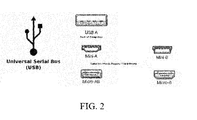
- the USB adapter port 9 can be optimized for different situations. For example the charging port's physical size and power carrying capabilities, to allow high efficiency power across various situations and need not be limited to only one type of adapter. It may take other form as shown in FIG 2 .; USB A, Mini A, Micro AB. Also, this particular adapter port's 9 main characteristic is to be mechanically and electrically coupled with any external device with similar connectivity 10.
- the external device 10 can be directly coupled to the USB adapter port 9 or through an adapter USB extension cord.
- the High Power Rechargeable Flashlight Fig. 3 is controlled when the flashlight power switch 2 sends a signal to the micro-controller 5 to tell it that the flashlight mode is active and therefore disable all other features.
- the circuitry converts the USB adapter 9 into an input device where current is drawn from an external adapter to recharge the internal battery 1 of the flashlight to power the LED light 4.
- the micro-controller 5 processes this information and allows the current to flow from the USB adapter port 9, to the battery charging circuit 8, the internal battery 1, the LED driver circuit and finally into the high powered led light 4.
- the charging circuit 8 is a switching regulator. Its primary function is to limit the current and voltage potential to the internal battery 1 received from the USB adapter port 9 typically five volt of direct current as per industry standard.
- a LED driver circuit 3 is provided for regulating the amount of current provided to the LED light 4.
- Section A describes the secondary function of the universal serial bus (USB) 9 which is to output and transfer energy from the internal battery 1 into small rechargeable electronic devices such as mobile phones, digital cameras, mp3 and similar consumer products.
- USB universal serial bus
- This mode is activated when the user selects to use the USB manual electronic switch 7.
- the electronic switch 7 sends a signal to the micro-controller 5 indicating to toggle to the secondary function and turn the USB adapter port 9 into a power sourcing device. Sourcing device means that the energy transfer will now flow from the internal battery 1 out to the external device 10.
- the way we accomplish this function is to have the micro-controller 5, send a signal to the output power supply circuit 6 to activate and transfer the energy from the internal battery 1 into the USB adapter port 9.
- the power supply circuit 6 is a buck regulator that lowers the higher potential voltage from the battery typically above seven volt of direct current down to five volt of direct current which is the industry standard output voltage of a USB adapter port 9. This power supply circuit 6, allows control of the maximum current deliver to the external device 10.
Abstract
Description
- Rechargeable Flashlights and Portable Power
- The present invention is a handheld flashlight with integrated portable power capabilities via two-way universal serial bus (USB). Flashlights are useful portable devices that provide light to users in the event of power outages, nighttime outdoor activities and many other circumstances. This invention combines the utility of a flashlight and a backup power source for recharging various electronic devices.
- The invention is a high power rechargeable flashlight with two way universal serial bus (USB) This handheld flashlight with integrated portable power capabilities via two way universal serial bus provides the utility of a traditional flashlight with the benefit of on the go backup power. Flashlights are useful portable light sources and are common to almost every home. With our increased reliance on smart phones, tablet style computers and related portable devices, back up power is essential when away from a primary charging source such as a home outlet or automobile. The present invention with its universal serial bus with the assistance of an adapter is capable of powering and transferring energy to small rechargeable electronic devices. Additionally, the invention uses the same universal serial bus to draw energy from an external adapter to recharge its own internal battery. The invention utilizes USB adapters and modifies their electrical characteristics to allow the adapter to serve the two purposes of both powering and transferring energy to small electronics or recharging itself through the same port. Currently, other market available designs required dual adapters to accomplish this function. The user can take advantage of the present invention by having a built-in USB adapter port that can recharge and power their small portable devices as well as acting as a rechargeable light source, namely a flashlight.
-
-
FIG.1 is a block diagram of the internal functions of the universal serial bus (USB) control circuit including the function of the rechargeable high power LED flashlight. -
FIG. 2 is a physical appearance of various universal serial ports available that can be used in combination with the flashlight. -
FIG. 3 shows a perspective view of the preferred embodiment with built in universal serial bus (USB). -
Figure 1 shows an internal diagram of the present invention and all its major electrical components. The circuitry is divided into section A and section B. Section A describes the major components and internal circuits of the bidirectional universal serial bus (USB) 9 circuit operation. Section B shows the internal circuit operation of the high power rechargeable flashlight. The combination of both circuits are essential to the invention. TheUSB adapter port 9 can be optimized for different situations. For example the charging port's physical size and power carrying capabilities, to allow high efficiency power across various situations and need not be limited to only one type of adapter. It may take other form as shown inFIG 2 .; USB A, Mini A, Micro AB. Also, this particular adapter port's 9 main characteristic is to be mechanically and electrically coupled with any external device withsimilar connectivity 10. Theexternal device 10 can be directly coupled to theUSB adapter port 9 or through an adapter USB extension cord. - In Section B of
FIG. 1 , the High Power Rechargeable FlashlightFig. 3 is controlled when theflashlight power switch 2 sends a signal to the micro-controller 5 to tell it that the flashlight mode is active and therefore disable all other features. In this scenario, the circuitry converts theUSB adapter 9 into an input device where current is drawn from an external adapter to recharge theinternal battery 1 of the flashlight to power theLED light 4. The micro-controller 5 processes this information and allows the current to flow from theUSB adapter port 9, to the battery charging circuit 8, theinternal battery 1, the LED driver circuit and finally into the high powered ledlight 4. The charging circuit 8 is a switching regulator. Its primary function is to limit the current and voltage potential to theinternal battery 1 received from theUSB adapter port 9 typically five volt of direct current as per industry standard. Moreover, a LED driver circuit 3 is provided for regulating the amount of current provided to theLED light 4. - Section A describes the secondary function of the universal serial bus (USB) 9 which is to output and transfer energy from the
internal battery 1 into small rechargeable electronic devices such as mobile phones, digital cameras, mp3 and similar consumer products. This mode is activated when the user selects to use the USB manual electronic switch 7. The electronic switch 7 sends a signal to the micro-controller 5 indicating to toggle to the secondary function and turn theUSB adapter port 9 into a power sourcing device. Sourcing device means that the energy transfer will now flow from theinternal battery 1 out to theexternal device 10. The way we accomplish this function is to have the micro-controller 5, send a signal to the output power supply circuit 6 to activate and transfer the energy from theinternal battery 1 into theUSB adapter port 9. The power supply circuit 6 is a buck regulator that lowers the higher potential voltage from the battery typically above seven volt of direct current down to five volt of direct current which is the industry standard output voltage of aUSB adapter port 9. This power supply circuit 6, allows control of the maximum current deliver to theexternal device 10.
Claims (13)
- A high power rechargeable light source device comprising a bidirectional universal serial bus (USB) adapter (9) being connected to an internal battery (1), and a light means (4), wherein the internal battery (1) can be charged via the bidirectional USB adapted (9) for providing current to the light means (4) or to an external rechargeable device (10).
- The high power rechargeable light source device according to claim 1, wherein the internal battery (1) is configured to provide energy to the light means (1) and to the external rechargeable device (10).
- The high power rechargeable light source device according to claim 1 or 2, wherein the light means (1) is a high power LED light.
- The high power rechargeable light source device according to any one of the claims 1-3, wherein a micro-controller (5) is provided for controlling the transfer of energy from the internal battery (1) into the bidirectional USB adapted (9) or to the light means (4).
- The high power rechargeable light source device according to any one of the preceding claims, wherein a battery charging circuit (8) is provided for limiting the current and voltage potential to the internal battery (1) received from the USB adapter (9).
- The high power rechargeable light source device according to claim 5, wherein the amount of voltage potential is about 5 volts.
- The high power rechargeable light source device according to any one of the preceding claims, wherein a LED driver circuit (3) is provided for regulating the amount of current provided to the LED light (4).
- The high power rechargeable light source device according to any one of the preceding claims, wherein the device further comprises a USB manual electronic switch (7) being configured to send a signal to the micro-controller (5) to toggle to a secondary function and turn the USB adapter (9) into a power sourcing device.
- The high power rechargeable light source device according to claim 8, wherein the power sourcing device transfers the energy from the external battery (1) out to the external device.
- The high power rechargeable light source device according to any one of the preceding claims, wherein a output power supply circuit (6) is provided to active and transfer the energy from the internal battery (1) into the USB adapter (9).
- The high power rechargeable light source device according to claim 10, wherein the output power supply circuit (6) is a buck regulator capable of lowering a higher potential voltage from the internal battery (1) from a voltage of about 7 volts of direct current down to 5 volts current.
- The high power rechargeable light source device according to claim 10 or 11, wherein the output power supply circuit (6) allows control of a maximum current delivered to the external device (10).
- The high power rechargeable light source device according to any one of the preceding claims, wherein the light source is a flashlight.
Applications Claiming Priority (2)
| Application Number | Priority Date | Filing Date | Title |
|---|---|---|---|
| US201361865811P | 2013-08-14 | 2013-08-14 | |
| US14/321,895 US9515419B2 (en) | 2013-08-14 | 2014-07-02 | High power rechargeable flashlight with two way universal serial BUS |
Publications (3)
| Publication Number | Publication Date |
|---|---|
| EP2849539A2 true EP2849539A2 (en) | 2015-03-18 |
| EP2849539A3 EP2849539A3 (en) | 2015-09-09 |
| EP2849539B1 EP2849539B1 (en) | 2019-11-27 |
Family
ID=51383545
Family Applications (1)
| Application Number | Title | Priority Date | Filing Date |
|---|---|---|---|
| EP14180544.0A Active EP2849539B1 (en) | 2013-08-14 | 2014-08-11 | High Power Rechargeable Flashlight WithTwo Way Universal Serial BUS |
Country Status (3)
| Country | Link |
|---|---|
| US (1) | US9515419B2 (en) |
| EP (1) | EP2849539B1 (en) |
| CA (1) | CA2858623C (en) |
Cited By (1)
| Publication number | Priority date | Publication date | Assignee | Title |
|---|---|---|---|---|
| EP3101333A1 (en) * | 2015-06-04 | 2016-12-07 | Inskeep, Mathew | Portable light device |
Families Citing this family (9)
| Publication number | Priority date | Publication date | Assignee | Title |
|---|---|---|---|---|
| US9651208B2 (en) | 2013-02-22 | 2017-05-16 | Streamlight, Inc. | Portable light chargeable from different sources |
| US10539276B2 (en) * | 2016-12-14 | 2020-01-21 | Vector Products, Inc | High power rechargeable spotlight with two way universal serial bus |
| US10892636B2 (en) | 2018-03-30 | 2021-01-12 | Hewlett Packard Enterprise Development Lp | Plug-in backup energy devices |
| US10605418B2 (en) | 2018-07-26 | 2020-03-31 | E. Mishan & Sons, Inc. | Rechargeable flashlight |
| US10936032B2 (en) * | 2018-12-11 | 2021-03-02 | Dell Products L.P. | Information handling system dual charger power balancing and fast role swapping |
| USD945037S1 (en) | 2020-04-14 | 2022-03-01 | E. Mishan & Sons, Inc. | Flashlight |
| US11705683B2 (en) | 2020-04-22 | 2023-07-18 | Black & Decker Inc. | Battery pack power transfer adaptor |
| USD972756S1 (en) * | 2020-11-19 | 2022-12-13 | Minghua Zhou | Flashlight |
| US11639789B2 (en) | 2021-01-13 | 2023-05-02 | Streamlight, Inc. | Portable light and keyed rechargeable USB battery |
Family Cites Families (20)
| Publication number | Priority date | Publication date | Assignee | Title |
|---|---|---|---|---|
| US20020038394A1 (en) * | 2000-09-25 | 2002-03-28 | Yeong-Chang Liang | USB sync-charger and methods of use related thereto |
| US7093153B1 (en) * | 2002-10-30 | 2006-08-15 | Advanced Micro Devices, Inc. | Method and apparatus for lowering bus clock frequency in a complex integrated data processing system |
| US7525291B1 (en) * | 2003-01-21 | 2009-04-28 | Microsemi Corporation | Linearly regulated battery charger |
| TWM288990U (en) * | 2005-11-08 | 2006-03-21 | Cal Comp Electronics & Comm Co | Function-switchable connection device |
| US8190785B2 (en) * | 2006-05-26 | 2012-05-29 | Smart Technologies Ulc | Plug-and-play device and method for enhancing features and settings in an interactive display system |
| US20070285053A1 (en) * | 2006-06-12 | 2007-12-13 | Teledex, Inc. | Portable charger |
| US8391921B2 (en) * | 2007-02-13 | 2013-03-05 | Google Inc. | Modular wireless communicator |
| CN104052870B (en) * | 2007-02-13 | 2018-09-11 | 谷歌有限责任公司 | modular wireless communicator |
| TWI324428B (en) * | 2007-03-28 | 2010-05-01 | Hybrid green uninterruptible power system and bi-directional converter module and power conversion method thereof | |
| CA2692395A1 (en) * | 2007-07-06 | 2009-01-15 | Kerry Berland | Unidirectional usb port |
| KR100951858B1 (en) * | 2007-12-17 | 2010-04-13 | 현대자동차주식회사 | USB port insertable into the bothdirection of vehicle |
| US8200852B2 (en) * | 2009-10-09 | 2012-06-12 | Dell Products, L.P. | Multi-mode dongle for peripheral devices and associated methods |
| US8564220B2 (en) * | 2010-05-20 | 2013-10-22 | Dan R. Matthews | Lighting device, lighting system, and method of use |
| EP2454956A1 (en) * | 2010-11-19 | 2012-05-23 | Philip Morris Products S.A. | An electrically heated smoking system comprising at least two units |
| US9973016B2 (en) * | 2011-08-10 | 2018-05-15 | Halo2Cloud, LLC | Portable power charger with two-way charging interface |
| EP2602721B1 (en) * | 2011-12-07 | 2017-07-12 | VIA Technologies, Inc. | USB charging module |
| WO2013112610A1 (en) * | 2012-01-23 | 2013-08-01 | Tsuga Engineering Llc | Portable rechargeable power supply |
| TWM436994U (en) * | 2012-03-21 | 2012-09-01 | Guangdong Jetfast Portable Lighting Co Ltd | Illumination and moveable charging device with touch switch |
| TWM439905U (en) * | 2012-04-26 | 2012-10-21 | Gigastone Corp | Mobile power source device having card reading function |
| US20150003050A1 (en) * | 2013-07-01 | 2015-01-01 | Armament Systems And Procedures, Inc. | Flashlight with hidden charge plug |
-
2014
- 2014-07-02 US US14/321,895 patent/US9515419B2/en active Active
- 2014-08-07 CA CA2858623A patent/CA2858623C/en active Active
- 2014-08-11 EP EP14180544.0A patent/EP2849539B1/en active Active
Non-Patent Citations (1)
| Title |
|---|
| None |
Cited By (1)
| Publication number | Priority date | Publication date | Assignee | Title |
|---|---|---|---|---|
| EP3101333A1 (en) * | 2015-06-04 | 2016-12-07 | Inskeep, Mathew | Portable light device |
Also Published As
| Publication number | Publication date |
|---|---|
| CA2858623A1 (en) | 2015-02-14 |
| US9515419B2 (en) | 2016-12-06 |
| CA2858623C (en) | 2022-08-02 |
| US20160006179A1 (en) | 2016-01-07 |
| EP2849539B1 (en) | 2019-11-27 |
| EP2849539A3 (en) | 2015-09-09 |
| US20160211616A9 (en) | 2016-07-21 |
Similar Documents
| Publication | Publication Date | Title |
|---|---|---|
| EP2849539B1 (en) | High Power Rechargeable Flashlight WithTwo Way Universal Serial BUS | |
| US9843208B2 (en) | High power rechargeable flashlight with two way universal serial bus | |
| US10250056B2 (en) | Multi-function external attachment and safety circuit for a portable power charger | |
| US20110012552A1 (en) | Electrical power source | |
| US20130082543A1 (en) | Portable power supply | |
| US20170194806A1 (en) | Portable Power Station Unit With Two Way Universal Serial BUS | |
| CN104868529A (en) | Wearable electronic device and charging method thereof | |
| TWI574486B (en) | Charging Device | |
| CN204131172U (en) | Multifunctional portable power source | |
| CN204012791U (en) | A kind of portable power source with wireless charging function | |
| CN112087016A (en) | Adapter | |
| CN104377789A (en) | Portable multifunctional portable power supply | |
| TWI600252B (en) | Mobile charge-discharge device | |
| JP3147870U (en) | Variable charging device | |
| US20150372521A1 (en) | Portable Power Bank | |
| TWI554000B (en) | Mobile charge-discharge device | |
| US11054092B2 (en) | High power rechargeable spotlight with two way universal serial bus | |
| CN211319480U (en) | Multi-power output multimedia equipment | |
| CN103398298A (en) | USB (universal serial bus) flashlight | |
| US20200195048A1 (en) | One Touch Charger | |
| US20150162756A1 (en) | Back-up power supply for mobile phone | |
| CN104467111A (en) | Wallet | |
| CN104953630A (en) | Mobile power source | |
| KR20070000812U (en) | Rechargeable FM radio and additional battery for mobile phone by USB port | |
| US20150097514A1 (en) | Smart mobile power device |
Legal Events
| Date | Code | Title | Description |
|---|---|---|---|
| PUAI | Public reference made under article 153(3) epc to a published international application that has entered the european phase |
Free format text: ORIGINAL CODE: 0009012 |
|
| 17P | Request for examination filed |
Effective date: 20140811 |
|
| AK | Designated contracting states |
Kind code of ref document: A2 Designated state(s): AL AT BE BG CH CY CZ DE DK EE ES FI FR GB GR HR HU IE IS IT LI LT LU LV MC MK MT NL NO PL PT RO RS SE SI SK SM TR |
|
| AX | Request for extension of the european patent |
Extension state: BA ME |
|
| PUAL | Search report despatched |
Free format text: ORIGINAL CODE: 0009013 |
|
| AK | Designated contracting states |
Kind code of ref document: A3 Designated state(s): AL AT BE BG CH CY CZ DE DK EE ES FI FR GB GR HR HU IE IS IT LI LT LU LV MC MK MT NL NO PL PT RO RS SE SI SK SM TR |
|
| AX | Request for extension of the european patent |
Extension state: BA ME |
|
| RIC1 | Information provided on ipc code assigned before grant |
Ipc: H02J 7/00 20060101ALI20150803BHEP Ipc: F21S 8/00 20060101ALI20150803BHEP Ipc: G06F 1/26 20060101ALI20150803BHEP Ipc: H05B 33/08 20060101AFI20150803BHEP |
|
| R17P | Request for examination filed (corrected) |
Effective date: 20160308 |
|
| RBV | Designated contracting states (corrected) |
Designated state(s): AL AT BE BG CH CY CZ DE DK EE ES FI FR GB GR HR HU IE IS IT LI LT LU LV MC MK MT NL NO PL PT RO RS SE SI SK SM TR |
|
| STAA | Information on the status of an ep patent application or granted ep patent |
Free format text: STATUS: EXAMINATION IS IN PROGRESS |
|
| 17Q | First examination report despatched |
Effective date: 20181015 |
|
| GRAP | Despatch of communication of intention to grant a patent |
Free format text: ORIGINAL CODE: EPIDOSNIGR1 |
|
| STAA | Information on the status of an ep patent application or granted ep patent |
Free format text: STATUS: GRANT OF PATENT IS INTENDED |
|
| INTG | Intention to grant announced |
Effective date: 20190731 |
|
| GRAS | Grant fee paid |
Free format text: ORIGINAL CODE: EPIDOSNIGR3 |
|
| GRAA | (expected) grant |
Free format text: ORIGINAL CODE: 0009210 |
|
| STAA | Information on the status of an ep patent application or granted ep patent |
Free format text: STATUS: THE PATENT HAS BEEN GRANTED |
|
| REG | Reference to a national code |
Ref country code: DE Ref legal event code: R079 Ref document number: 602014057397 Country of ref document: DE Free format text: PREVIOUS MAIN CLASS: H05B0033080000 Ipc: H05B0045000000 |
|
| AK | Designated contracting states |
Kind code of ref document: B1 Designated state(s): AL AT BE BG CH CY CZ DE DK EE ES FI FR GB GR HR HU IE IS IT LI LT LU LV MC MK MT NL NO PL PT RO RS SE SI SK SM TR |
|
| REG | Reference to a national code |
Ref country code: GB Ref legal event code: FG4D |
|
| REG | Reference to a national code |
Ref country code: CH Ref legal event code: EP |
|
| REG | Reference to a national code |
Ref country code: AT Ref legal event code: REF Ref document number: 1208195 Country of ref document: AT Kind code of ref document: T Effective date: 20191215 |
|
| REG | Reference to a national code |
Ref country code: DE Ref legal event code: R096 Ref document number: 602014057397 Country of ref document: DE |
|
| REG | Reference to a national code |
Ref country code: IE Ref legal event code: FG4D |
|
| REG | Reference to a national code |
Ref country code: NL Ref legal event code: MP Effective date: 20191127 |
|
| REG | Reference to a national code |
Ref country code: LT Ref legal event code: MG4D |
|
| PG25 | Lapsed in a contracting state [announced via postgrant information from national office to epo] |
Ref country code: FI Free format text: LAPSE BECAUSE OF FAILURE TO SUBMIT A TRANSLATION OF THE DESCRIPTION OR TO PAY THE FEE WITHIN THE PRESCRIBED TIME-LIMIT Effective date: 20191127 Ref country code: BG Free format text: LAPSE BECAUSE OF FAILURE TO SUBMIT A TRANSLATION OF THE DESCRIPTION OR TO PAY THE FEE WITHIN THE PRESCRIBED TIME-LIMIT Effective date: 20200227 Ref country code: GR Free format text: LAPSE BECAUSE OF FAILURE TO SUBMIT A TRANSLATION OF THE DESCRIPTION OR TO PAY THE FEE WITHIN THE PRESCRIBED TIME-LIMIT Effective date: 20200228 Ref country code: LT Free format text: LAPSE BECAUSE OF FAILURE TO SUBMIT A TRANSLATION OF THE DESCRIPTION OR TO PAY THE FEE WITHIN THE PRESCRIBED TIME-LIMIT Effective date: 20191127 Ref country code: NL Free format text: LAPSE BECAUSE OF FAILURE TO SUBMIT A TRANSLATION OF THE DESCRIPTION OR TO PAY THE FEE WITHIN THE PRESCRIBED TIME-LIMIT Effective date: 20191127 Ref country code: ES Free format text: LAPSE BECAUSE OF FAILURE TO SUBMIT A TRANSLATION OF THE DESCRIPTION OR TO PAY THE FEE WITHIN THE PRESCRIBED TIME-LIMIT Effective date: 20191127 Ref country code: SE Free format text: LAPSE BECAUSE OF FAILURE TO SUBMIT A TRANSLATION OF THE DESCRIPTION OR TO PAY THE FEE WITHIN THE PRESCRIBED TIME-LIMIT Effective date: 20191127 Ref country code: NO Free format text: LAPSE BECAUSE OF FAILURE TO SUBMIT A TRANSLATION OF THE DESCRIPTION OR TO PAY THE FEE WITHIN THE PRESCRIBED TIME-LIMIT Effective date: 20200227 Ref country code: LV Free format text: LAPSE BECAUSE OF FAILURE TO SUBMIT A TRANSLATION OF THE DESCRIPTION OR TO PAY THE FEE WITHIN THE PRESCRIBED TIME-LIMIT Effective date: 20191127 |
|
| PG25 | Lapsed in a contracting state [announced via postgrant information from national office to epo] |
Ref country code: IS Free format text: LAPSE BECAUSE OF FAILURE TO SUBMIT A TRANSLATION OF THE DESCRIPTION OR TO PAY THE FEE WITHIN THE PRESCRIBED TIME-LIMIT Effective date: 20200327 Ref country code: RS Free format text: LAPSE BECAUSE OF FAILURE TO SUBMIT A TRANSLATION OF THE DESCRIPTION OR TO PAY THE FEE WITHIN THE PRESCRIBED TIME-LIMIT Effective date: 20191127 Ref country code: HR Free format text: LAPSE BECAUSE OF FAILURE TO SUBMIT A TRANSLATION OF THE DESCRIPTION OR TO PAY THE FEE WITHIN THE PRESCRIBED TIME-LIMIT Effective date: 20191127 |
|
| PG25 | Lapsed in a contracting state [announced via postgrant information from national office to epo] |
Ref country code: AL Free format text: LAPSE BECAUSE OF FAILURE TO SUBMIT A TRANSLATION OF THE DESCRIPTION OR TO PAY THE FEE WITHIN THE PRESCRIBED TIME-LIMIT Effective date: 20191127 |
|
| PG25 | Lapsed in a contracting state [announced via postgrant information from national office to epo] |
Ref country code: RO Free format text: LAPSE BECAUSE OF FAILURE TO SUBMIT A TRANSLATION OF THE DESCRIPTION OR TO PAY THE FEE WITHIN THE PRESCRIBED TIME-LIMIT Effective date: 20191127 Ref country code: CZ Free format text: LAPSE BECAUSE OF FAILURE TO SUBMIT A TRANSLATION OF THE DESCRIPTION OR TO PAY THE FEE WITHIN THE PRESCRIBED TIME-LIMIT Effective date: 20191127 Ref country code: EE Free format text: LAPSE BECAUSE OF FAILURE TO SUBMIT A TRANSLATION OF THE DESCRIPTION OR TO PAY THE FEE WITHIN THE PRESCRIBED TIME-LIMIT Effective date: 20191127 Ref country code: DK Free format text: LAPSE BECAUSE OF FAILURE TO SUBMIT A TRANSLATION OF THE DESCRIPTION OR TO PAY THE FEE WITHIN THE PRESCRIBED TIME-LIMIT Effective date: 20191127 Ref country code: PT Free format text: LAPSE BECAUSE OF FAILURE TO SUBMIT A TRANSLATION OF THE DESCRIPTION OR TO PAY THE FEE WITHIN THE PRESCRIBED TIME-LIMIT Effective date: 20200419 |
|
| REG | Reference to a national code |
Ref country code: DE Ref legal event code: R097 Ref document number: 602014057397 Country of ref document: DE |
|
| PG25 | Lapsed in a contracting state [announced via postgrant information from national office to epo] |
Ref country code: SK Free format text: LAPSE BECAUSE OF FAILURE TO SUBMIT A TRANSLATION OF THE DESCRIPTION OR TO PAY THE FEE WITHIN THE PRESCRIBED TIME-LIMIT Effective date: 20191127 Ref country code: SM Free format text: LAPSE BECAUSE OF FAILURE TO SUBMIT A TRANSLATION OF THE DESCRIPTION OR TO PAY THE FEE WITHIN THE PRESCRIBED TIME-LIMIT Effective date: 20191127 |
|
| REG | Reference to a national code |
Ref country code: AT Ref legal event code: MK05 Ref document number: 1208195 Country of ref document: AT Kind code of ref document: T Effective date: 20191127 |
|
| PLBE | No opposition filed within time limit |
Free format text: ORIGINAL CODE: 0009261 |
|
| STAA | Information on the status of an ep patent application or granted ep patent |
Free format text: STATUS: NO OPPOSITION FILED WITHIN TIME LIMIT |
|
| 26N | No opposition filed |
Effective date: 20200828 |
|
| PG25 | Lapsed in a contracting state [announced via postgrant information from national office to epo] |
Ref country code: PL Free format text: LAPSE BECAUSE OF FAILURE TO SUBMIT A TRANSLATION OF THE DESCRIPTION OR TO PAY THE FEE WITHIN THE PRESCRIBED TIME-LIMIT Effective date: 20191127 Ref country code: AT Free format text: LAPSE BECAUSE OF FAILURE TO SUBMIT A TRANSLATION OF THE DESCRIPTION OR TO PAY THE FEE WITHIN THE PRESCRIBED TIME-LIMIT Effective date: 20191127 Ref country code: SI Free format text: LAPSE BECAUSE OF FAILURE TO SUBMIT A TRANSLATION OF THE DESCRIPTION OR TO PAY THE FEE WITHIN THE PRESCRIBED TIME-LIMIT Effective date: 20191127 |
|
| PG25 | Lapsed in a contracting state [announced via postgrant information from national office to epo] |
Ref country code: IT Free format text: LAPSE BECAUSE OF FAILURE TO SUBMIT A TRANSLATION OF THE DESCRIPTION OR TO PAY THE FEE WITHIN THE PRESCRIBED TIME-LIMIT Effective date: 20191127 |
|
| PG25 | Lapsed in a contracting state [announced via postgrant information from national office to epo] |
Ref country code: MC Free format text: LAPSE BECAUSE OF FAILURE TO SUBMIT A TRANSLATION OF THE DESCRIPTION OR TO PAY THE FEE WITHIN THE PRESCRIBED TIME-LIMIT Effective date: 20191127 |
|
| REG | Reference to a national code |
Ref country code: CH Ref legal event code: PL |
|
| PG25 | Lapsed in a contracting state [announced via postgrant information from national office to epo] |
Ref country code: LU Free format text: LAPSE BECAUSE OF NON-PAYMENT OF DUE FEES Effective date: 20200811 Ref country code: LI Free format text: LAPSE BECAUSE OF NON-PAYMENT OF DUE FEES Effective date: 20200831 Ref country code: CH Free format text: LAPSE BECAUSE OF NON-PAYMENT OF DUE FEES Effective date: 20200831 |
|
| REG | Reference to a national code |
Ref country code: BE Ref legal event code: MM Effective date: 20200831 |
|
| PG25 | Lapsed in a contracting state [announced via postgrant information from national office to epo] |
Ref country code: IE Free format text: LAPSE BECAUSE OF NON-PAYMENT OF DUE FEES Effective date: 20200811 Ref country code: BE Free format text: LAPSE BECAUSE OF NON-PAYMENT OF DUE FEES Effective date: 20200831 |
|
| PG25 | Lapsed in a contracting state [announced via postgrant information from national office to epo] |
Ref country code: TR Free format text: LAPSE BECAUSE OF FAILURE TO SUBMIT A TRANSLATION OF THE DESCRIPTION OR TO PAY THE FEE WITHIN THE PRESCRIBED TIME-LIMIT Effective date: 20191127 Ref country code: MT Free format text: LAPSE BECAUSE OF FAILURE TO SUBMIT A TRANSLATION OF THE DESCRIPTION OR TO PAY THE FEE WITHIN THE PRESCRIBED TIME-LIMIT Effective date: 20191127 Ref country code: CY Free format text: LAPSE BECAUSE OF FAILURE TO SUBMIT A TRANSLATION OF THE DESCRIPTION OR TO PAY THE FEE WITHIN THE PRESCRIBED TIME-LIMIT Effective date: 20191127 |
|
| PG25 | Lapsed in a contracting state [announced via postgrant information from national office to epo] |
Ref country code: MK Free format text: LAPSE BECAUSE OF FAILURE TO SUBMIT A TRANSLATION OF THE DESCRIPTION OR TO PAY THE FEE WITHIN THE PRESCRIBED TIME-LIMIT Effective date: 20191127 |
|
| PGFP | Annual fee paid to national office [announced via postgrant information from national office to epo] |
Ref country code: GB Payment date: 20230828 Year of fee payment: 10 |
|
| PGFP | Annual fee paid to national office [announced via postgrant information from national office to epo] |
Ref country code: FR Payment date: 20230825 Year of fee payment: 10 Ref country code: DE Payment date: 20230829 Year of fee payment: 10 |