EP2849318A2 - Electric power for vehicles - Google Patents
Electric power for vehicles Download PDFInfo
- Publication number
- EP2849318A2 EP2849318A2 EP14179798.5A EP14179798A EP2849318A2 EP 2849318 A2 EP2849318 A2 EP 2849318A2 EP 14179798 A EP14179798 A EP 14179798A EP 2849318 A2 EP2849318 A2 EP 2849318A2
- Authority
- EP
- European Patent Office
- Prior art keywords
- inverter
- electric motor
- drive unit
- cooling circuit
- vehicle
- Prior art date
- Legal status (The legal status is an assumption and is not a legal conclusion. Google has not performed a legal analysis and makes no representation as to the accuracy of the status listed.)
- Granted
Links
- 238000001816 cooling Methods 0.000 claims abstract description 38
- 230000008878 coupling Effects 0.000 claims description 21
- 238000010168 coupling process Methods 0.000 claims description 21
- 238000005859 coupling reaction Methods 0.000 claims description 21
- 238000012423 maintenance Methods 0.000 abstract description 7
- 238000009434 installation Methods 0.000 abstract description 2
- 238000010276 construction Methods 0.000 abstract 1
- 230000005540 biological transmission Effects 0.000 description 9
- 239000002826 coolant Substances 0.000 description 7
- 238000002485 combustion reaction Methods 0.000 description 4
- 239000002245 particle Substances 0.000 description 3
- 239000012530 fluid Substances 0.000 description 2
- 230000002411 adverse Effects 0.000 description 1
- 230000000712 assembly Effects 0.000 description 1
- 238000000429 assembly Methods 0.000 description 1
- 230000002051 biphasic effect Effects 0.000 description 1
- 230000001627 detrimental effect Effects 0.000 description 1
- 238000000926 separation method Methods 0.000 description 1
Images

Classifications
-
- B—PERFORMING OPERATIONS; TRANSPORTING
- B60—VEHICLES IN GENERAL
- B60L—PROPULSION OF ELECTRICALLY-PROPELLED VEHICLES; SUPPLYING ELECTRIC POWER FOR AUXILIARY EQUIPMENT OF ELECTRICALLY-PROPELLED VEHICLES; ELECTRODYNAMIC BRAKE SYSTEMS FOR VEHICLES IN GENERAL; MAGNETIC SUSPENSION OR LEVITATION FOR VEHICLES; MONITORING OPERATING VARIABLES OF ELECTRICALLY-PROPELLED VEHICLES; ELECTRIC SAFETY DEVICES FOR ELECTRICALLY-PROPELLED VEHICLES
- B60L3/00—Electric devices on electrically-propelled vehicles for safety purposes; Monitoring operating variables, e.g. speed, deceleration or energy consumption
- B60L3/0023—Detecting, eliminating, remedying or compensating for drive train abnormalities, e.g. failures within the drive train
- B60L3/0061—Detecting, eliminating, remedying or compensating for drive train abnormalities, e.g. failures within the drive train relating to electrical machines
-
- B—PERFORMING OPERATIONS; TRANSPORTING
- B60—VEHICLES IN GENERAL
- B60L—PROPULSION OF ELECTRICALLY-PROPELLED VEHICLES; SUPPLYING ELECTRIC POWER FOR AUXILIARY EQUIPMENT OF ELECTRICALLY-PROPELLED VEHICLES; ELECTRODYNAMIC BRAKE SYSTEMS FOR VEHICLES IN GENERAL; MAGNETIC SUSPENSION OR LEVITATION FOR VEHICLES; MONITORING OPERATING VARIABLES OF ELECTRICALLY-PROPELLED VEHICLES; ELECTRIC SAFETY DEVICES FOR ELECTRICALLY-PROPELLED VEHICLES
- B60L1/00—Supplying electric power to auxiliary equipment of vehicles
- B60L1/02—Supplying electric power to auxiliary equipment of vehicles to electric heating circuits
-
- B—PERFORMING OPERATIONS; TRANSPORTING
- B60—VEHICLES IN GENERAL
- B60L—PROPULSION OF ELECTRICALLY-PROPELLED VEHICLES; SUPPLYING ELECTRIC POWER FOR AUXILIARY EQUIPMENT OF ELECTRICALLY-PROPELLED VEHICLES; ELECTRODYNAMIC BRAKE SYSTEMS FOR VEHICLES IN GENERAL; MAGNETIC SUSPENSION OR LEVITATION FOR VEHICLES; MONITORING OPERATING VARIABLES OF ELECTRICALLY-PROPELLED VEHICLES; ELECTRIC SAFETY DEVICES FOR ELECTRICALLY-PROPELLED VEHICLES
- B60L3/00—Electric devices on electrically-propelled vehicles for safety purposes; Monitoring operating variables, e.g. speed, deceleration or energy consumption
- B60L3/0023—Detecting, eliminating, remedying or compensating for drive train abnormalities, e.g. failures within the drive train
- B60L3/003—Detecting, eliminating, remedying or compensating for drive train abnormalities, e.g. failures within the drive train relating to inverters
-
- B—PERFORMING OPERATIONS; TRANSPORTING
- B60—VEHICLES IN GENERAL
- B60L—PROPULSION OF ELECTRICALLY-PROPELLED VEHICLES; SUPPLYING ELECTRIC POWER FOR AUXILIARY EQUIPMENT OF ELECTRICALLY-PROPELLED VEHICLES; ELECTRODYNAMIC BRAKE SYSTEMS FOR VEHICLES IN GENERAL; MAGNETIC SUSPENSION OR LEVITATION FOR VEHICLES; MONITORING OPERATING VARIABLES OF ELECTRICALLY-PROPELLED VEHICLES; ELECTRIC SAFETY DEVICES FOR ELECTRICALLY-PROPELLED VEHICLES
- B60L50/00—Electric propulsion with power supplied within the vehicle
- B60L50/10—Electric propulsion with power supplied within the vehicle using propulsion power supplied by engine-driven generators, e.g. generators driven by combustion engines
- B60L50/16—Electric propulsion with power supplied within the vehicle using propulsion power supplied by engine-driven generators, e.g. generators driven by combustion engines with provision for separate direct mechanical propulsion
-
- B—PERFORMING OPERATIONS; TRANSPORTING
- B60—VEHICLES IN GENERAL
- B60L—PROPULSION OF ELECTRICALLY-PROPELLED VEHICLES; SUPPLYING ELECTRIC POWER FOR AUXILIARY EQUIPMENT OF ELECTRICALLY-PROPELLED VEHICLES; ELECTRODYNAMIC BRAKE SYSTEMS FOR VEHICLES IN GENERAL; MAGNETIC SUSPENSION OR LEVITATION FOR VEHICLES; MONITORING OPERATING VARIABLES OF ELECTRICALLY-PROPELLED VEHICLES; ELECTRIC SAFETY DEVICES FOR ELECTRICALLY-PROPELLED VEHICLES
- B60L50/00—Electric propulsion with power supplied within the vehicle
- B60L50/50—Electric propulsion with power supplied within the vehicle using propulsion power supplied by batteries or fuel cells
- B60L50/51—Electric propulsion with power supplied within the vehicle using propulsion power supplied by batteries or fuel cells characterised by AC-motors
-
- B—PERFORMING OPERATIONS; TRANSPORTING
- B60—VEHICLES IN GENERAL
- B60L—PROPULSION OF ELECTRICALLY-PROPELLED VEHICLES; SUPPLYING ELECTRIC POWER FOR AUXILIARY EQUIPMENT OF ELECTRICALLY-PROPELLED VEHICLES; ELECTRODYNAMIC BRAKE SYSTEMS FOR VEHICLES IN GENERAL; MAGNETIC SUSPENSION OR LEVITATION FOR VEHICLES; MONITORING OPERATING VARIABLES OF ELECTRICALLY-PROPELLED VEHICLES; ELECTRIC SAFETY DEVICES FOR ELECTRICALLY-PROPELLED VEHICLES
- B60L58/00—Methods or circuit arrangements for monitoring or controlling batteries or fuel cells, specially adapted for electric vehicles
- B60L58/10—Methods or circuit arrangements for monitoring or controlling batteries or fuel cells, specially adapted for electric vehicles for monitoring or controlling batteries
- B60L58/24—Methods or circuit arrangements for monitoring or controlling batteries or fuel cells, specially adapted for electric vehicles for monitoring or controlling batteries for controlling the temperature of batteries
- B60L58/26—Methods or circuit arrangements for monitoring or controlling batteries or fuel cells, specially adapted for electric vehicles for monitoring or controlling batteries for controlling the temperature of batteries by cooling
-
- B—PERFORMING OPERATIONS; TRANSPORTING
- B60—VEHICLES IN GENERAL
- B60K—ARRANGEMENT OR MOUNTING OF PROPULSION UNITS OR OF TRANSMISSIONS IN VEHICLES; ARRANGEMENT OR MOUNTING OF PLURAL DIVERSE PRIME-MOVERS IN VEHICLES; AUXILIARY DRIVES FOR VEHICLES; INSTRUMENTATION OR DASHBOARDS FOR VEHICLES; ARRANGEMENTS IN CONNECTION WITH COOLING, AIR INTAKE, GAS EXHAUST OR FUEL SUPPLY OF PROPULSION UNITS IN VEHICLES
- B60K11/00—Arrangement in connection with cooling of propulsion units
- B60K11/02—Arrangement in connection with cooling of propulsion units with liquid cooling
-
- B—PERFORMING OPERATIONS; TRANSPORTING
- B60—VEHICLES IN GENERAL
- B60K—ARRANGEMENT OR MOUNTING OF PROPULSION UNITS OR OF TRANSMISSIONS IN VEHICLES; ARRANGEMENT OR MOUNTING OF PLURAL DIVERSE PRIME-MOVERS IN VEHICLES; AUXILIARY DRIVES FOR VEHICLES; INSTRUMENTATION OR DASHBOARDS FOR VEHICLES; ARRANGEMENTS IN CONNECTION WITH COOLING, AIR INTAKE, GAS EXHAUST OR FUEL SUPPLY OF PROPULSION UNITS IN VEHICLES
- B60K1/00—Arrangement or mounting of electrical propulsion units
- B60K2001/003—Arrangement or mounting of electrical propulsion units with means for cooling the electrical propulsion units
- B60K2001/006—Arrangement or mounting of electrical propulsion units with means for cooling the electrical propulsion units the electric motors
-
- B—PERFORMING OPERATIONS; TRANSPORTING
- B60—VEHICLES IN GENERAL
- B60L—PROPULSION OF ELECTRICALLY-PROPELLED VEHICLES; SUPPLYING ELECTRIC POWER FOR AUXILIARY EQUIPMENT OF ELECTRICALLY-PROPELLED VEHICLES; ELECTRODYNAMIC BRAKE SYSTEMS FOR VEHICLES IN GENERAL; MAGNETIC SUSPENSION OR LEVITATION FOR VEHICLES; MONITORING OPERATING VARIABLES OF ELECTRICALLY-PROPELLED VEHICLES; ELECTRIC SAFETY DEVICES FOR ELECTRICALLY-PROPELLED VEHICLES
- B60L2240/00—Control parameters of input or output; Target parameters
- B60L2240/10—Vehicle control parameters
- B60L2240/36—Temperature of vehicle components or parts
-
- Y—GENERAL TAGGING OF NEW TECHNOLOGICAL DEVELOPMENTS; GENERAL TAGGING OF CROSS-SECTIONAL TECHNOLOGIES SPANNING OVER SEVERAL SECTIONS OF THE IPC; TECHNICAL SUBJECTS COVERED BY FORMER USPC CROSS-REFERENCE ART COLLECTIONS [XRACs] AND DIGESTS
- Y02—TECHNOLOGIES OR APPLICATIONS FOR MITIGATION OR ADAPTATION AGAINST CLIMATE CHANGE
- Y02T—CLIMATE CHANGE MITIGATION TECHNOLOGIES RELATED TO TRANSPORTATION
- Y02T10/00—Road transport of goods or passengers
- Y02T10/60—Other road transportation technologies with climate change mitigation effect
- Y02T10/70—Energy storage systems for electromobility, e.g. batteries
-
- Y—GENERAL TAGGING OF NEW TECHNOLOGICAL DEVELOPMENTS; GENERAL TAGGING OF CROSS-SECTIONAL TECHNOLOGIES SPANNING OVER SEVERAL SECTIONS OF THE IPC; TECHNICAL SUBJECTS COVERED BY FORMER USPC CROSS-REFERENCE ART COLLECTIONS [XRACs] AND DIGESTS
- Y02—TECHNOLOGIES OR APPLICATIONS FOR MITIGATION OR ADAPTATION AGAINST CLIMATE CHANGE
- Y02T—CLIMATE CHANGE MITIGATION TECHNOLOGIES RELATED TO TRANSPORTATION
- Y02T10/00—Road transport of goods or passengers
- Y02T10/60—Other road transportation technologies with climate change mitigation effect
- Y02T10/7072—Electromobility specific charging systems or methods for batteries, ultracapacitors, supercapacitors or double-layer capacitors
Definitions
- the invention relates to a drive unit for a vehicle and a vehicle with such a drive unit.
- the drive unit may in particular be designed to drive a vehicle.
- Hybrid drive For driving vehicles usually internal combustion engines, electric motor or combinations of these two types of drive in the form of a so-called. Hybrid drive is used.
- an electric motor and an inverter is required, which prepares and provides the required energy for the electric motor.
- such an inverter usually accesses direct current from a battery, converts the direct current into an alternating current and then outputs this to the electric motor.
- the inverter can be electrically connected to the battery by means of a two-phase high-voltage connection and to the electric motor by means of a three-phase high-voltage connection.
- Both the electric motor and the inverter generate in one operating state, a heat load, which must be removed, so as not to jeopardize the safe operation of these components.
- the drive unit as described below offers a spatially compact structure and increased resistance to mechanical stress, which can result, for example, from vibrations or heat loads.
- the inverter is to be electrically coupled to the electric motor via a three-phase connecting line in order to provide the drive energy.
- the three-phase connection line can be exposed to vibrations due to vibrations during operation of the drive unit or a driven vehicle or by temperature fluctuations of a high mechanical load, which, for example, bring about the risk of a disconnected connection and thus adversely affect the reliability of the drive unit.
- each interface of the inverter may require the use of a corresponding seal.
- a drive unit for a vehicle has an electric motor and an inverter.
- the inverter is designed to supply the electric motor with an operating voltage.
- the drive unit is characterized in that the electric motor and the inverter are connected to a common cooling circuit, via which the resulting in an operating state of the drive unit heat loads are transported to the electric motor and to the inverter.
- the inverter and the electric motor are arranged so that they are spatially close to each other or even adjoin one another.
- the electric motor and the inverter are arranged directly adjacent to each other.
- this structure makes it possible to provide a common cooling circuit for the electric motor and the inverter.
- the compact design is thereby supported because a coolant line including coolant can be used for cooling the two components.
- the cooling of the inverter can in particular be effected by means of a cooling plate through which a coolant runs in the cooling circuit and removes the heat load.
- the inverter is mechanically coupled to the electric motor so that the inverter is fixed to the electric motor.
- the mechanical coupling fixes the electric motor and the inverter with respect to each other and can reduce a mechanical load on the electrical connection lines between the inverter and the electric motor, which can contribute to increased reliability of the drive unit.
- the mechanical coupling of the electric motor with the inverter can reduce the risk of a leak at the electrical connection points between the electric motor and the inverter, so that the reliability can be further increased thereby.
- the inverter is mechanically coupled directly to the electric motor.
- inverter and the electric motor are fastened to one another with a mechanical connection, so that, for example, these two components represent a single assembly.
- a line-based connection between the components can be completely dispensed with, since the electrical connection can be produced, for example, via plug connections, contact connections or electrically conductive rails.
- the direct mechanical coupling of the inverter with the electric motor also eliminates an external interface of the inverter, which can reduce the effort to seal against the ingress of dirt particles or moisture, since now only the interface of the inverter to the battery must be sealed.
- the drive unit has a housing, wherein the electric motor and the inverter are arranged together within the housing.
- the electric motor and the inverter form a single unit and can allow a compact and simplified assembly of this unit. Likewise, this structure can reduce maintenance.
- the drive unit has a heat exchanger, wherein the heat exchanger is coupled to the common cooling circuit and is arranged outside the housing.
- the coolant absorbs a heat load from the electric motor and the inverter and outputs this heat load by means of the heat exchanger to the environment.
- the drive unit has a coupling element which mechanically couples the inverter to the electric motor.
- the coupling element may be, for example, a flange, which the two components electric motor and inverter by mechanical coupling connects directly with each other. This connects both components to a single assembly.
- the coupling element is designed to electrically couple the inverter to the electric motor via an electrical connection.
- the electrical connection replaces an external connection line, which is required when the electric motor and the inverter are arranged spatially separated from each other, so that just the maintenance and assembly costs caused by the external connection line is reduced.
- the electrical connection is a three-phase high-voltage connection.
- the AC voltage is transmitted, which is generated by the inverter, starting from a DC voltage of an energy source, for example in the form of a battery.
- the coupling element connects a first portion of the common cooling circuit to a second portion of the common cooling circuit, wherein the first portion of the common cooling circuit is arranged to remove a heat load from the electric motor and wherein the second portion of the common cooling circuit is arranged, a heat load to be removed from the inverter.
- the coupling element connects the extending through the electric motor first portion of the common cooling circuit with the running through the inverter second portion of the common cooling circuit to a single closed cooling circuit, so that through this cooling circuit, a coolant can flow and the in can dissipate the electric motor and the inverter resulting heat load through a heat exchanger environment.
- the coupling element may, for example, have two recesses or openings which, in the assembled state of the drive unit, connect cooling circuits in the electric motor and in the inverter, designed as fluid channels, so that a coolant can flow unhindered through the fluid channels.
- the coupling element may be designed as a separate interface element separate from the electric motor and the inverter.
- the coupling element may be integral with the electric motor or the inverter and allow the coupling of the other component.
- the drive unit has a housing, wherein the electric motor and the inverter are arranged together within the housing.
- a vehicle in another aspect, is provided with a drive unit as described above and below.
- the drive unit is designed to drive the vehicle.
- the vehicle may be a passenger car or a commercial vehicle.
- the drive unit may be designed as part of a hybrid drive for the vehicle and together with an internal combustion engine provide the drive energy for a vehicle.
- Fig. 1 shows a drive unit 100 with an internal combustion engine 110, an electric motor in the form of an electric motor 120 and a transmission 130 for transmitting torque via a torque transmitting element in the form of a shaft 115 for driving a vehicle.
- the electric motor 120 is coupled to the shaft 115 such that a torque of the electric motor can be applied to the shaft 115 as an alternative or in addition to the torque of the internal combustion engine 110.
- the electric motor 120 is energized via an inverter 140, the inverter 140 being configured to be supplied with DC voltage of a battery 150 via a biphasic power transmission line 152, converting the DC voltage to an AC voltage, and supplying the AC voltage to the electric motor via a three-phase power transmission line 142 transferred to.
- the drive unit 100 has two cooling circuits 160A, 160B, each with its own associated heat exchanger 165A or 165B.
- the first cooling circuit 160A is configured to dissipate heat loads from the battery 150 and the inverter 140.
- the second cooling circuit 160B is configured to dissipate heat loads from the electric motor 120.
- the separation of the cooling circuits 160A, 160B may result from the electric motor 120 and the inverter 140 being mounted separately from each other. This separate assembly may be particularly detrimental to the power transmission line 142, which may be subject to mechanical stresses due to vibration and / or temperature variations. Therefore, can For example, a regular maintenance or replacement of the power transmission line 142 may be required.
- Fig. 2 shows a drive unit 100, in which the electric motor 120 and the inverter 140 have a common cooling circuit 160B and are mechanically coupled directly to each other.
- the cooling circuit passes through a cooling plate 141 of the inverter 140, wherein the cooling plate 141 is mechanically and thermally coupled to the inverter 140 such that a heat load is transferred from the inverter to the cooling plate and removed from the cooling plate via the cooling circuit by means of a coolant.
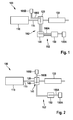
- Fig. 3 shows an electric motor 120 and an inverter 140, which are arranged in a common housing 122.
- the electric motor and the inverter are realized as a single component.
- a coupling or connecting element 124 is arranged, which mechanically and electrically couples the electric motor 120 and the inverter 140 together.
- the electrical connection 142 replaces the transmission line 142 as shown in FIG Fig. 1 is shown.
- the coupling and connecting element 124 can in particular be designed as a flange and connect cooling channels 160B-2, which run in a cooling plate 141 of the inverter 140, with cooling channels 160B-1, which run in the electric motor 120, so that they have a common cooling circuit form and connected to a common heat exchanger 165B.
Abstract
Es ist eine Antriebseinheit (100) für ein Fahrzeug angegeben. Die Antriebseinheit (100) weist einen Elektromotor (120) und einen Inverter (140) auf. Der Inverter (140) ist ausgeführt, den Elektromotor (120) mit einer Betriebsspannung zu versorgen. Die Antriebseinheit (100) ist dadurch gekennzeichnet, dass der Elektromotor (120) und der Inverter (140) an einem gemeinsamen Kühlkreislauf (160B) angeschlossen sind, über welchen die in einem Betriebszustand der Antriebseinheit (100) anfallenden Wärmelasten an dem Elektromotor (120) und an dem Inverter (140) abtransportiert werden. Dies ermöglicht einen räumlich kompakten Aufbau der Antriebseinheit und einen Verzicht auf einige Verbindungsleitungen, so dass ein geringerer Montage- und Wartungsaufwand entsteht.A drive unit (100) for a vehicle is indicated. The drive unit (100) has an electric motor (120) and an inverter (140). The inverter (140) is designed to supply the electric motor (120) with an operating voltage. The drive unit (100) is characterized in that the electric motor (120) and the inverter (140) are connected to a common cooling circuit (160B) via which the heat loads occurring in an operating state of the drive unit (100) are applied to the electric motor (120). and be transported to the inverter (140). This allows a spatially compact construction of the drive unit and a waiver of some connecting lines, so that less installation and maintenance costs.
Description
Die Erfindung betrifft eine Antriebseinheit für ein Fahrzeug sowie ein Fahrzeug mit einer solchen Antriebseinheit. Die Antriebseinheit kann insbesondere ausgeführt sein, ein Fahrzeug anzutreiben.The invention relates to a drive unit for a vehicle and a vehicle with such a drive unit. The drive unit may in particular be designed to drive a vehicle.
Zum Antreiben von Fahrzeugen werden üblicherweise Verbrennungskraftmaschinen, Elektrokraftmaschinen oder Kombinationen dieser beiden Antriebsarten in Form eines sog. Hybridantriebs verwendet.For driving vehicles usually internal combustion engines, electric motor or combinations of these two types of drive in the form of a so-called. Hybrid drive is used.
Zum Betreiben einer einzelnen Elektrokraftmaschine oder einer Elektrokraftmaschine im Rahmen eines Hybridantriebs wird ein Elektromotor sowie ein Inverter benötigt, der die erforderliche Energie für den Elektromotor aufbereitet und bereitstellt.To operate a single electric motor or an electric motor in the context of a hybrid drive, an electric motor and an inverter is required, which prepares and provides the required energy for the electric motor.
Dabei greift ein solcher Inverter üblicherweise auf Gleichstrom aus einer Batterie zurück, wandelt den Gleichstrom in einen Wechselstrom um und gibt diesen dann an den Elektromotor aus. Der Inverter kann dabei mit der Batterie mittels einer zweiphasigen Hochspannungsverbindung und mit dem Elektromotor mittels einer dreiphasigen Hochspannungsverbindung elektrisch verbunden sein.In this case, such an inverter usually accesses direct current from a battery, converts the direct current into an alternating current and then outputs this to the electric motor. The inverter can be electrically connected to the battery by means of a two-phase high-voltage connection and to the electric motor by means of a three-phase high-voltage connection.
Sowohl der Elektromotor als auch der Inverter erzeugen in einem Betriebszustand eine Wärmelast, welche abtransportiert werden muss, um den sicheren Betrieb dieser Komponenten nicht zu gefährden.Both the electric motor and the inverter generate in one operating state, a heat load, which must be removed, so as not to jeopardize the safe operation of these components.
Die Antriebseinheit wie im Folgenden beschrieben bietet einen räumlich kompakten Aufbau sowie eine erhöhte Resistenz gegen mechanische Belastungen, die beispielsweise aus Erschütterungen oder Wärmebelastungen resultieren können.The drive unit as described below offers a spatially compact structure and increased resistance to mechanical stress, which can result, for example, from vibrations or heat loads.
Werden der Elektromotor und der Inverter als separate Baugruppen gefertigt und montiert, so ist der Inverter über eine dreiphasige Verbindungsleitung mit dem Elektromotor elektrisch zu koppeln, um die Antriebsenergie bereit zu stellen. Die dreiphasige Verbindungsleitung kann durch Vibrationen während des Betriebs der Antriebseinheit oder eines angetriebenen Fahrzeugs oder durch Temperaturschwankungen einer hohen mechanischen Belastung ausgesetzt sein, welche beispielsweise die Gefahr einer gelösten Verbindung herbeiführen und damit die Betriebssicherheit der Antriebseinheit negativ beeinflussen kann.If the electric motor and the inverter are manufactured and assembled as separate assemblies, then the inverter is to be electrically coupled to the electric motor via a three-phase connecting line in order to provide the drive energy. The three-phase connection line can be exposed to vibrations due to vibrations during operation of the drive unit or a driven vehicle or by temperature fluctuations of a high mechanical load, which, for example, bring about the risk of a disconnected connection and thus adversely affect the reliability of the drive unit.
Weiterhin kann es in Abhängigkeit von den Montagepositionen des Elektromotors und des Inverters im Rahmen von Wartungs- oder Reparaturarbeiten erforderlich sein, dass die dreiphasige Verbindungsleitung zwischen dem Inverter und dem Elektromotor gelöst werden muss, was insbesondere durch den Umstand der anliegenden hohen Spannung an dieser dreiphasigen Verbindungsleitung die Ausführung unter hohen Sicherheitsanforderungen durch Fachpersonal erfordern kann.Furthermore, depending on the mounting positions of the electric motor and the inverter in the course of maintenance or repair work may be required that the three-phase connection line between the inverter and the electric motor must be solved, in particular by the fact of the high voltage applied to this three-phase connection line the execution under high safety requirements by qualified personnel may require.
Je nach Position des Inverters kann es auch erforderlich sein, diesen gegen das Eindringen von Schmutzpartikeln oder Feuchtigkeit abzudichten, um seine Betriebssicherheit zu gewährleisten. Jede Schnittstelle des Inverters kann die Verwendung einer entsprechenden Abdichtung erfordern.Depending on the position of the inverter, it may also be necessary to seal it against the ingress of dirt particles or moisture in order to ensure its operational safety. Each interface of the inverter may require the use of a corresponding seal.
Gemäß einem Aspekt ist eine Antriebseinheit für ein Fahrzeug angegeben. Die Antriebseinheit weist einen Elektromotor und einen Inverter auf. Der Inverter ist ausgeführt, den Elektromotor mit einer Betriebsspannung zu versorgen. Die Antriebseinheit ist dadurch gekennzeichnet, dass der Elektromotor und der Inverter an einem gemeinsamen Kühlkreislauf angeschlossen sind, über welchen die in einem Betriebszustand der Antriebseinheit anfallenden Wärmelasten an dem Elektromotor und an dem Inverter abtransportiert werden.According to one aspect, a drive unit for a vehicle is specified. The drive unit has an electric motor and an inverter. The inverter is designed to supply the electric motor with an operating voltage. The drive unit is characterized in that the electric motor and the inverter are connected to a common cooling circuit, via which the resulting in an operating state of the drive unit heat loads are transported to the electric motor and to the inverter.
Der Inverter und der Elektromotor sind so angeordnet, dass diese räumlich nahe beieinander liegen oder sogar aneinander grenzen. Insbesondere in einem montierten Zustand in einem Fahrzeug sind der Elektromotor und der Inverter unmittelbar aneinandergrenzend angeordnet.The inverter and the electric motor are arranged so that they are spatially close to each other or even adjoin one another. In particular, in a mounted state in a vehicle, the electric motor and the inverter are arranged directly adjacent to each other.
Damit ermöglicht dieser Aufbau das Bereitstellen eines gemeinsamen Kühlkreislaufs für den Elektromotor und den Inverter. Die kompakte Bauweise wird hierdurch unterstützt, da eine Kühlmittelleitung samt Kühlmittel zum Kühlen der beiden Komponenten verwendet werden kann.Thus, this structure makes it possible to provide a common cooling circuit for the electric motor and the inverter. The compact design is thereby supported because a coolant line including coolant can be used for cooling the two components.
Die Kühlung des Inverters kann insbesondere mittels einer Kühlplatte erfolgen, durch die ein Kühlmittel in dem Kühlkreislauf verläuft und die Wärmelast abtransportiert.The cooling of the inverter can in particular be effected by means of a cooling plate through which a coolant runs in the cooling circuit and removes the heat load.
Gemäß einer Ausführungsform ist der Inverter mit dem Elektromotor so mechanisch gekoppelt, dass der Inverter an dem Elektromotor fixiert ist.According to one embodiment, the inverter is mechanically coupled to the electric motor so that the inverter is fixed to the electric motor.
Dies bedeutet, dass der Inverter und der Elektromotor als ein einzelnes Bauteil ausgeführt sind. Die mechanische Kopplung fixiert den Elektromotor und den Inverter mit Bezug zueinander und kann eine mechanische Belastung der elektrischen Verbindungsleitungen zwischen dem Inverter und dem Elektromotor reduzieren, was zu einer erhöhten Betriebssicherheit der Antriebseinheit beitragen kann.This means that the inverter and the electric motor are designed as a single component. The mechanical coupling fixes the electric motor and the inverter with respect to each other and can reduce a mechanical load on the electrical connection lines between the inverter and the electric motor, which can contribute to increased reliability of the drive unit.
Daneben kann die mechanische Kopplung des Elektromotors mit dem Inverter die Gefahr einer undichten Stelle an den elektrischen Verbindungspunkten zwischen dem Elektromotor und dem Inverter reduzieren, so dass die Betriebssicherheit hierdurch weiter erhöht werden kann.In addition, the mechanical coupling of the electric motor with the inverter can reduce the risk of a leak at the electrical connection points between the electric motor and the inverter, so that the reliability can be further increased thereby.
Gemäß einer weiteren Ausführungsform ist der Inverter unmittelbar mit dem Elektromotor mechanisch gekoppelt.According to a further embodiment, the inverter is mechanically coupled directly to the electric motor.
Dies bedeutet, dass der Inverter und der Elektromotor mit einer mechanischen Verbindung aneinander befestigt sind, so dass beispielsweise diese beiden Komponenten eine einzelne Baugruppe darstellen.This means that the inverter and the electric motor are fastened to one another with a mechanical connection, so that, for example, these two components represent a single assembly.
In dieser Ausführungsform kann vollständig auf eine leitungsbasierte Verbindung zwischen den Komponenten verzichtet werden, da die elektrische Verbindung beispielsweise über Steckverbindungen, Kontaktverbindungen oder elektrisch leitfähige Schienen hergestellt werden kann.In this embodiment, a line-based connection between the components can be completely dispensed with, since the electrical connection can be produced, for example, via plug connections, contact connections or electrically conductive rails.
Damit entfällt die Gefahr, dass durch mechanische Belastung einer Verbindungsleitung zwischen Elektromotor und Inverter die Betriebssicherheit beeinflusst werden kann, da es die elektrische Verbindung in Form einer Leitung gar nicht mehr gibt.This eliminates the risk that the reliability can be influenced by mechanical stress on a connecting line between the electric motor and inverter, since there is no longer the electrical connection in the form of a line.
Ebenso kann ein Wartungsaufwand der Antriebseinheit reduziert werden, da gerade die Verbindungsleitung, welche einer hohen mechanischen Belastung ausgesetzt sein kann, entfällt.Likewise, a maintenance of the drive unit can be reduced, since just the connecting line, which may be exposed to high mechanical stress, is eliminated.
Durch die unmittelbare mechanische Kopplung des Inverters mit dem Elektromotor entfällt darüber hinaus eine externe Schnittstelle des Inverters, was den Aufwand zum Abdichten gegen das Eindringen von Schmutzpartikeln oder Feuchtigkeit reduzieren kann, da nunmehr nur noch die Schnittstelle des Inverters zu der Batterie abgedichtet werden muss.The direct mechanical coupling of the inverter with the electric motor also eliminates an external interface of the inverter, which can reduce the effort to seal against the ingress of dirt particles or moisture, since now only the interface of the inverter to the battery must be sealed.
Gemäß einer weiteren Ausführungsform weist die Antriebseinheit ein Gehäuse auf, wobei der Elektromotor und der Inverter gemeinsam innerhalb des Gehäuses angeordnet sind.According to a further embodiment, the drive unit has a housing, wherein the electric motor and the inverter are arranged together within the housing.
Damit bilden der Elektromotor und der Inverter eine einzelne Baueinheit und können eine kompakte und vereinfachte Montage dieser Baueinheit ermöglichen. Ebenso kann dieser Aufbau einen Wartungsaufwand reduzieren.Thus, the electric motor and the inverter form a single unit and can allow a compact and simplified assembly of this unit. Likewise, this structure can reduce maintenance.
Gemäß einer weiteren Ausführungsform weist die Antriebseinheit einen Wärmetauscher auf, wobei der Wärmetauscher mit dem gemeinsamen Kühlkreislauf gekoppelt ist und außerhalb des Gehäuses angeordnet ist.According to a further embodiment, the drive unit has a heat exchanger, wherein the heat exchanger is coupled to the common cooling circuit and is arranged outside the housing.
Das Kühlmittel nimmt eine Wärmelast von dem Elektromotor und dem Inverter auf und gibt diese Wärmelast mittels des Wärmetauschers an die Umgebung ab.The coolant absorbs a heat load from the electric motor and the inverter and outputs this heat load by means of the heat exchanger to the environment.
Gemäß einer weiteren Ausführungsform weist die Antriebseinheit ein Kopplungselement auf, welches den Inverter mit dem Elektromotor mechanisch koppelt.According to a further embodiment, the drive unit has a coupling element which mechanically couples the inverter to the electric motor.
Das Kopplungselement kann beispielsweise ein Flansch sein, welcher die beiden Komponenten Elektromotor und Inverter durch mechanische Kopplung unmittelbar miteinander verbindet. Damit werden beide Komponenten zu einer einzelnen Baugruppe verbunden.The coupling element may be, for example, a flange, which the two components electric motor and inverter by mechanical coupling connects directly with each other. This connects both components to a single assembly.
Gemäß einer weiteren Ausführungsform ist das Kopplungselement ausgeführt, den Inverter mit dem Elektromotor über eine elektrische Verbindung elektrisch zu koppeln.According to a further embodiment, the coupling element is designed to electrically couple the inverter to the electric motor via an electrical connection.
Die elektrische Verbindung ersetzt eine externe Verbindungsleitung, welche erforderlich ist, wenn der Elektromotor und der Inverter räumlich voneinander getrennt angeordnet bzw. montiert sind, so dass gerade der durch die externe Verbindungsleitung verursachte Wartungs- und Montageaufwand reduziert wird.The electrical connection replaces an external connection line, which is required when the electric motor and the inverter are arranged spatially separated from each other, so that just the maintenance and assembly costs caused by the external connection line is reduced.
Gemäß einer weiteren Ausführungsform ist die elektrische Verbindung eine dreiphasige Hochspannungsverbindung.According to a further embodiment, the electrical connection is a three-phase high-voltage connection.
Über eine solche dreiphasige Hochspannungsverbindung wird die Wechselspannung übertragen, welche von dem Inverter ausgehend von einer Gleichspannung einer Energiequelle, beispielsweise in Form einer Batterie, erzeugt wird.About such a three-phase high-voltage connection, the AC voltage is transmitted, which is generated by the inverter, starting from a DC voltage of an energy source, for example in the form of a battery.
Gemäß einer weiteren Ausführungsform verbindet das Kopplungselement einen ersten Abschnitt des gemeinsamen Kühlkreislaufs mit einem zweiten Abschnitt des gemeinsamen Kühlkreislaufs, wobei der erste Abschnitt des gemeinsamen Kühlkreislaufs angeordnet ist, eine Wärmelast von dem Elektromotor abzutransportieren und wobei der zweite Abschnitt des gemeinsamen Kühlkreislaufs angeordnet ist, eine Wärmelast von dem Inverter abzutransportieren.According to a further embodiment, the coupling element connects a first portion of the common cooling circuit to a second portion of the common cooling circuit, wherein the first portion of the common cooling circuit is arranged to remove a heat load from the electric motor and wherein the second portion of the common cooling circuit is arranged, a heat load to be removed from the inverter.
In einem gekoppelten oder montierten Zustand der Antriebseinheit verbindet das Kopplungselement den durch den Elektromotor verlaufenden ersten Abschnitt des gemeinsamen Kühlkreislaufs mit dem durch den Inverter verlaufenden zweiten Abschnitt des gemeinsamen Kühlkreislaufs zu einem einzigen geschlossenen Kühlkreislauf, so dass durch diesen Kühlkreislauf ein Kühlmittel fließen kann und die in dem Elektromotor und dem Inverter anfallende Wärmelast über einen Wärmetauscher der Umgebung abführen kann.In a coupled or mounted state of the drive unit, the coupling element connects the extending through the electric motor first portion of the common cooling circuit with the running through the inverter second portion of the common cooling circuit to a single closed cooling circuit, so that through this cooling circuit, a coolant can flow and the in can dissipate the electric motor and the inverter resulting heat load through a heat exchanger environment.
Hierzu kann das Kopplungselement beispielsweise zwei Ausnehmungen bzw. Durchbrüche aufweisen, welche in dem montierten Zustand der Antriebseinheit als Fluidkanäle ausgeführte Kühlkreisläufe in dem Elektromotor und in dem Inverter miteinander verbinden, so dass ein Kühlmittel ungehindert durch die Fluidkanäle fließen kann.For this purpose, the coupling element may, for example, have two recesses or openings which, in the assembled state of the drive unit, connect cooling circuits in the electric motor and in the inverter, designed as fluid channels, so that a coolant can flow unhindered through the fluid channels.
Das Kopplungselement kann als eigenes Schnittstellenelement getrennt von dem Elektromotor und dem Inverter ausgeführt sein. Alternativ kann das Kopplungselement integral mit dem Elektromotor oder dem Inverter ausgeführt sein und ein Ankoppeln der jeweils anderen Komponente ermöglichen.The coupling element may be designed as a separate interface element separate from the electric motor and the inverter. Alternatively, the coupling element may be integral with the electric motor or the inverter and allow the coupling of the other component.
Gemäß einer weiteren Ausführungsform weist die Antriebseinheit ein Gehäuse auf, wobei der Elektromotor und der Inverter gemeinsam innerhalb des Gehäuses angeordnet sind.According to a further embodiment, the drive unit has a housing, wherein the electric motor and the inverter are arranged together within the housing.
Gemäß einem weiteren Aspekt ist ein Fahrzeug mit einer Antriebseinheit wie oben und im Folgenden beschrieben angegeben. Dabei ist die Antriebseinheit ausgeführt, das Fahrzeug anzutreiben.In another aspect, a vehicle is provided with a drive unit as described above and below. The drive unit is designed to drive the vehicle.
Bei dem Fahrzeug kann es sich um einen Personenkraftwagen oder um ein Nutzfahrzeug handeln. Die Antriebseinheit kann insbesondere als Teil eines Hybridantriebs für das Fahrzeug ausgeführt sein und gemeinsam mit einem Verbrennungsmotor die Antriebsenergie für ein Fahrzeug bereitstellen.The vehicle may be a passenger car or a commercial vehicle. In particular, the drive unit may be designed as part of a hybrid drive for the vehicle and together with an internal combustion engine provide the drive energy for a vehicle.
Im Folgenden werden mit Bezug zu den Zeichnungen Ausführungsbeispiele der Erfindung beschrieben. Dabei zeigen:
-
Fig. 1 eine schematische Darstellung einer Antriebseinheit. -
Fig. 2 eine schematische Darstellung einer Antriebseinheit gemäß einem Ausführungsbeispiel. -
Fig. 3 eine schematische Darstellung einer Antriebseinheit gemäß einem weiteren Ausführungsbeispiel.
-
Fig. 1 a schematic representation of a drive unit. -
Fig. 2 a schematic representation of a drive unit according to an embodiment. -
Fig. 3 a schematic representation of a drive unit according to another embodiment.
Die Darstellungen in den Figuren sind schematisch und nicht maßstabsgetreu. Werden gleiche Bezugsziffern verwendet, so betreffen diese gleiche oder ähnliche Elemente.The illustrations in the figures are schematic and not to scale. If the same reference numerals are used, these relate to the same or similar elements.
Der Elektromotor 120 ist mit der Welle 115 so gekoppelt, dass ein Drehmoment des Elektromotors alternativ oder zusätzlich zu dem Drehmoment der Verbrennungskraftmaschine 110 auf die Welle 115 beaufschlagt werden kann.The
Der Elektromotor 120 wird über einen Inverter 140 mit Energie versorgt, wobei der Inverter 140 ausgeführt ist, über eine zweiphasige Energieübertragungsleitung 152 mit Gleichspannung einer Batterie 150 versorgt zu werden, die Gleichspannung in eine Wechselspannung umzuwandeln und die Wechselspannung über eine dreiphasige Energieübertragungsleitung 142 an den Elektromotor zu übertragen.The
Die Antriebseinheit 100 weist zwei Kühlkreisläufe 160A, 160B mit jeweils einem eigenen zugeordneten Wärmetauscher 165A bzw. 165B auf. Der erste Kühlkreislauf 160A ist ausgeführt, Wärmelasten von der Batterie 150 und dem Inverter 140 abzuführen. Der zweite Kühlkreislauf 160B ist ausgeführt, Wärmelasten von dem Elektromotor 120 abzuführen.The
Die Trennung der Kühlkreisläufe 160A, 160B kann daraus resultieren, dass der Elektromotor 120 und der Inverter 140 räumlich voneinander getrennt montiert sind. Diese getrennte Montage kann insbesondere nachteilig hinsichtlich der Energieübertragungsleitung 142 sein, welche mechanischen Belastungen durch Vibration und/oder Temperaturschwankungen ausgesetzt sein kann. Daher kann beispielsweise eine regelmäßige Wartung bzw. ein Ersetzen der Energieübertragungsleitung 142 erforderlich sein.The separation of the
Damit entfällt die Energieübertragungsleitung 142 aus
Ebenso kann durch diese Anordnung die Gefahr einer undichten Verbindung an den elektrischen Kopplungspunkten zwischen Elektromotor und Inverter reduziert werden, insbesondere da diese elektrische Kopplung durch den Elektromotor und den an dem Elektromotor mechanisch angekoppelten Inverter baulich gegen das Eindringen von Schmutzpartikeln und Feuchtigkeit abgeschirmt ist.Likewise, the danger of a leaky connection to the electrical coupling points between the electric motor and inverter can be reduced by this arrangement, especially since this electrical coupling is shielded by the electric motor and the mechanically coupled to the electric motor inverter structurally against the ingress of dirt particles and moisture.
Es verbleibt lediglich die zweiphasige Energieübertragungsleitung 152 von der Batterie 150 zu dem Inverter 140.Only the two-phase
Zwischen dem Elektromotor 120 und dem Inverter 140 ist ein Kopplungs- bzw. Verbindungselement 124 angeordnet, welches den Elektromotor 120 und den Inverter 140 mechanisch und elektrisch miteinander koppelt. Die elektrische Verbindung 142 ersetzt die Übertragungsleitung 142, wie sie in
Claims (9)
wobei der Inverter (140) mit dem Elektromotor (120) so mechanisch gekoppelt ist, dass der Inverter (140) an dem Elektromotor (120) fixiert ist.Drive unit (100) according to claim 1,
wherein the inverter (140) is mechanically coupled to the electric motor (120) such that the inverter (140) is fixed to the electric motor (120).
wobei die Antriebseinheit (100) ein Gehäuse (122) aufweist;
wobei der Elektromotor (120) und der Inverter (140) gemeinsam innerhalb des Gehäuses (122) angeordnet sind.Drive unit (100) according to one of claims 1 or 2,
wherein the drive unit (100) comprises a housing (122);
wherein the electric motor (120) and the inverter (140) are disposed in common within the housing (122).
weiterhin aufweisend einen Wärmetauscher (165B);
wobei der Wärmetauscher (165B) mit dem gemeinsamen Kühlkreislauf (160B) gekoppelt ist und außerhalb des Gehäuses (122) angeordnet ist.Drive unit (100) according to claim 3,
further comprising a heat exchanger (165B);
wherein the heat exchanger (165B) is coupled to the common cooling circuit (160B) and located outside of the housing (122).
wobei die Antriebseinheit (100) ein Kopplungselement (124) aufweist;
wobei das Kopplungselement (124) den Inverter (140) mit dem Elektromotor (120) mechanisch koppelt.Drive unit (100) according to one of the preceding claims,
wherein the drive unit (100) comprises a coupling element (124);
wherein the coupling element (124) mechanically couples the inverter (140) to the electric motor (120).
wobei das Kopplungselement (124) den Inverter (140) mit dem Elektromotor (120) über eine elektrische Verbindung (142) elektrisch koppelt.Drive unit (100) according to claim 4,
wherein the coupling element (124) electrically couples the inverter (140) to the electric motor (120) via an electrical connection (142).
wobei die elektrische Verbindung (142) eine dreiphasige Hochspannungsverbindung ist.Drive unit (100) according to claim 5,
wherein the electrical connection (142) is a three-phase high voltage connection.
wobei das Kopplungselement (124) einen ersten Abschnitt (160B-1) des gemeinsamen Kühlkreislaufs (160B) mit einem zweiten Abschnitt (160B-2) des gemeinsamen Kühlkreislaufs (160B) verbindet;
wobei der erste Abschnitt (160B-1) des gemeinsamen Kühlkreislaufs (160B) angeordnet ist, Wärmelasten von dem Elektromotor (120) abzutransportieren;
wobei der zweite Abschnitt (160B-2) des gemeinsamen Kühlkreislaufs (160B) angeordnet ist, Wärmelasten von dem Inverter (140) abzutransportieren.Drive unit (100) according to one of claims 4 to 6,
wherein the coupling member (124) connects a first portion (160B-1) of the common cooling circuit (160B) to a second portion (160B-2) of the common cooling circuit (160B);
wherein the first portion (160B-1) of the common cooling circuit (160B) is arranged to remove heat loads from the electric motor (120);
wherein the second portion (160B-2) of the common cooling circuit (160B) is arranged to remove heat loads from the inverter (140).
Applications Claiming Priority (1)
| Application Number | Priority Date | Filing Date | Title |
|---|---|---|---|
| DE102013218126.4A DE102013218126A1 (en) | 2013-09-11 | 2013-09-11 | Electric drive unit for vehicles |
Publications (3)
| Publication Number | Publication Date |
|---|---|
| EP2849318A2 true EP2849318A2 (en) | 2015-03-18 |
| EP2849318A3 EP2849318A3 (en) | 2016-04-27 |
| EP2849318B1 EP2849318B1 (en) | 2018-03-07 |
Family
ID=51302899
Family Applications (1)
| Application Number | Title | Priority Date | Filing Date |
|---|---|---|---|
| EP14179798.5A Active EP2849318B1 (en) | 2013-09-11 | 2014-08-05 | Electric power for vehicles |
Country Status (2)
| Country | Link |
|---|---|
| EP (1) | EP2849318B1 (en) |
| DE (1) | DE102013218126A1 (en) |
Cited By (1)
| Publication number | Priority date | Publication date | Assignee | Title |
|---|---|---|---|---|
| DE102020207346A1 (en) | 2020-06-15 | 2021-12-16 | Robert Bosch Gesellschaft mit beschränkter Haftung | Drive device for a vehicle and vehicle with a drive device |
Families Citing this family (2)
| Publication number | Priority date | Publication date | Assignee | Title |
|---|---|---|---|---|
| DE102017217584A1 (en) * | 2017-10-04 | 2019-04-04 | Siemens Aktiengesellschaft | Arrangement and method for cooling electric drive units |
| DE102020202203A1 (en) | 2020-02-20 | 2021-08-26 | Robert Bosch Gesellschaft mit beschränkter Haftung | Drive device with self-controlled cooling |
Family Cites Families (4)
| Publication number | Priority date | Publication date | Assignee | Title |
|---|---|---|---|---|
| JP5051456B2 (en) * | 2008-02-20 | 2012-10-17 | アイシン・エィ・ダブリュ株式会社 | Hybrid drive unit |
| DE102010002068A1 (en) * | 2010-02-18 | 2011-08-18 | Siemens Aktiengesellschaft, 80333 | motor unit |
| DE102010048131A1 (en) * | 2010-10-11 | 2012-04-12 | Magna Powertrain Ag & Co. Kg | Electrical drive unit for use as power source at axles in electrically or hybrid-electrically driven vehicle, has cooling circuit carrying coolant to cool stator and circuit, where coolant stays in heat exchanging connection to fluid |
| KR101418291B1 (en) * | 2011-04-27 | 2014-07-11 | 엘지전자 주식회사 | Electric motor and electric vechile having the same |
-
2013
- 2013-09-11 DE DE102013218126.4A patent/DE102013218126A1/en not_active Withdrawn
-
2014
- 2014-08-05 EP EP14179798.5A patent/EP2849318B1/en active Active
Non-Patent Citations (1)
| Title |
|---|
| None |
Cited By (2)
| Publication number | Priority date | Publication date | Assignee | Title |
|---|---|---|---|---|
| DE102020207346A1 (en) | 2020-06-15 | 2021-12-16 | Robert Bosch Gesellschaft mit beschränkter Haftung | Drive device for a vehicle and vehicle with a drive device |
| WO2021254707A1 (en) | 2020-06-15 | 2021-12-23 | Robert Bosch Gmbh | Drive assembly for a vehicle, and vehicle with a drive assembly |
Also Published As
| Publication number | Publication date |
|---|---|
| DE102013218126A1 (en) | 2015-03-12 |
| EP2849318A3 (en) | 2016-04-27 |
| EP2849318B1 (en) | 2018-03-07 |
Similar Documents
| Publication | Publication Date | Title |
|---|---|---|
| DE60223965T2 (en) | Power control unit for a vehicle | |
| DE102009027220A1 (en) | Device for supplying an electric drive for a motor vehicle | |
| DE102015214053A1 (en) | Electric drive unit, in particular for an electric vehicle | |
| EP3075062A2 (en) | Power electronics module and hybrid module with an e-motor power connection | |
| EP3132967B1 (en) | Charger for charging the traction battery of an electric vehicle and electric vehicle | |
| WO2015078464A1 (en) | Hybrid module with integrated power electronics | |
| DE102015218622A1 (en) | driving means | |
| DE112017005862T5 (en) | Power conversion device | |
| WO2019154685A1 (en) | Electric drive unit for a motor vehicle | |
| EP2849318B1 (en) | Electric power for vehicles | |
| DE112012004015T5 (en) | Control device for a motor vehicle inverter | |
| WO2015078465A1 (en) | Hybrid module and power electronics module with a common coolant flow | |
| WO2021047718A1 (en) | Coolable electric drive device, and drive arrangement | |
| WO2008011959A1 (en) | Motor vehicle | |
| EP3443645B1 (en) | Hybrid drive module for a motor vehicle drivetrain | |
| DE102017220550A1 (en) | Cooling system for a drive system and vehicle drive system | |
| DE102017121989A1 (en) | Hybrid drive arrangement for a motor vehicle | |
| DE102019006155A1 (en) | Energy distribution system for an at least partially electrically powered vehicle, in particular a utility vehicle, and method | |
| DE102008054637A1 (en) | Hybrid powertrain of a motor vehicle | |
| DE102016106104A1 (en) | Electric motor unit for mobile work machine | |
| DE102015012223A1 (en) | Drive unit for a motor vehicle | |
| DE102016218127A1 (en) | Cooling for a hybrid drive assembly | |
| DE102016218142A1 (en) | Between the drive module | |
| DE102012110930A1 (en) | Rotating electrical machine i.e. generator, for vehicle, has power converter, and coupling part comprising curved structure that is arranged between connection part and main module body for connecting connection part and body | |
| DE102008011593A1 (en) | Industrial truck i.e. counterweight fork-lift truck, has braking resistor integrated into housing of converter, and common cooling circuit provided for liquid cooling of converter and braking resistor |
Legal Events
| Date | Code | Title | Description |
|---|---|---|---|
| PUAI | Public reference made under article 153(3) epc to a published international application that has entered the european phase |
Free format text: ORIGINAL CODE: 0009012 |
|
| 17P | Request for examination filed |
Effective date: 20140805 |
|
| AK | Designated contracting states |
Kind code of ref document: A2 Designated state(s): AL AT BE BG CH CY CZ DE DK EE ES FI FR GB GR HR HU IE IS IT LI LT LU LV MC MK MT NL NO PL PT RO RS SE SI SK SM TR |
|
| AX | Request for extension of the european patent |
Extension state: BA ME |
|
| PUAL | Search report despatched |
Free format text: ORIGINAL CODE: 0009013 |
|
| AK | Designated contracting states |
Kind code of ref document: A3 Designated state(s): AL AT BE BG CH CY CZ DE DK EE ES FI FR GB GR HR HU IE IS IT LI LT LU LV MC MK MT NL NO PL PT RO RS SE SI SK SM TR |
|
| AX | Request for extension of the european patent |
Extension state: BA ME |
|
| RIC1 | Information provided on ipc code assigned before grant |
Ipc: B60K 11/02 20060101ALI20160321BHEP Ipc: B60L 11/18 20060101ALI20160321BHEP Ipc: B60L 11/14 20060101ALI20160321BHEP Ipc: B60L 1/02 20060101ALI20160321BHEP Ipc: B60L 3/00 20060101ALI20160321BHEP Ipc: H02K 11/00 20160101AFI20160321BHEP Ipc: B60K 1/00 20060101ALI20160321BHEP |
|
| R17P | Request for examination filed (corrected) |
Effective date: 20161027 |
|
| RBV | Designated contracting states (corrected) |
Designated state(s): AL AT BE BG CH CY CZ DE DK EE ES FI FR GB GR HR HU IE IS IT LI LT LU LV MC MK MT NL NO PL PT RO RS SE SI SK SM TR |
|
| GRAP | Despatch of communication of intention to grant a patent |
Free format text: ORIGINAL CODE: EPIDOSNIGR1 |
|
| INTG | Intention to grant announced |
Effective date: 20171113 |
|
| GRAS | Grant fee paid |
Free format text: ORIGINAL CODE: EPIDOSNIGR3 |
|
| GRAA | (expected) grant |
Free format text: ORIGINAL CODE: 0009210 |
|
| AK | Designated contracting states |
Kind code of ref document: B1 Designated state(s): AL AT BE BG CH CY CZ DE DK EE ES FI FR GB GR HR HU IE IS IT LI LT LU LV MC MK MT NL NO PL PT RO RS SE SI SK SM TR |
|
| REG | Reference to a national code |
Ref country code: GB Ref legal event code: FG4D Free format text: NOT ENGLISH |
|
| REG | Reference to a national code |
Ref country code: CH Ref legal event code: EP Ref country code: AT Ref legal event code: REF Ref document number: 977546 Country of ref document: AT Kind code of ref document: T Effective date: 20180315 |
|
| REG | Reference to a national code |
Ref country code: IE Ref legal event code: FG4D Free format text: LANGUAGE OF EP DOCUMENT: GERMAN |
|
| REG | Reference to a national code |
Ref country code: DE Ref legal event code: R096 Ref document number: 502014007509 Country of ref document: DE |
|
| REG | Reference to a national code |
Ref country code: NL Ref legal event code: MP Effective date: 20180307 |
|
| REG | Reference to a national code |
Ref country code: LT Ref legal event code: MG4D |
|
| PG25 | Lapsed in a contracting state [announced via postgrant information from national office to epo] |
Ref country code: LT Free format text: LAPSE BECAUSE OF FAILURE TO SUBMIT A TRANSLATION OF THE DESCRIPTION OR TO PAY THE FEE WITHIN THE PRESCRIBED TIME-LIMIT Effective date: 20180307 Ref country code: CY Free format text: LAPSE BECAUSE OF FAILURE TO SUBMIT A TRANSLATION OF THE DESCRIPTION OR TO PAY THE FEE WITHIN THE PRESCRIBED TIME-LIMIT Effective date: 20180307 Ref country code: HR Free format text: LAPSE BECAUSE OF FAILURE TO SUBMIT A TRANSLATION OF THE DESCRIPTION OR TO PAY THE FEE WITHIN THE PRESCRIBED TIME-LIMIT Effective date: 20180307 Ref country code: FI Free format text: LAPSE BECAUSE OF FAILURE TO SUBMIT A TRANSLATION OF THE DESCRIPTION OR TO PAY THE FEE WITHIN THE PRESCRIBED TIME-LIMIT Effective date: 20180307 Ref country code: NO Free format text: LAPSE BECAUSE OF FAILURE TO SUBMIT A TRANSLATION OF THE DESCRIPTION OR TO PAY THE FEE WITHIN THE PRESCRIBED TIME-LIMIT Effective date: 20180607 Ref country code: ES Free format text: LAPSE BECAUSE OF FAILURE TO SUBMIT A TRANSLATION OF THE DESCRIPTION OR TO PAY THE FEE WITHIN THE PRESCRIBED TIME-LIMIT Effective date: 20180307 |
|
| REG | Reference to a national code |
Ref country code: FR Ref legal event code: PLFP Year of fee payment: 5 |
|
| PG25 | Lapsed in a contracting state [announced via postgrant information from national office to epo] |
Ref country code: RS Free format text: LAPSE BECAUSE OF FAILURE TO SUBMIT A TRANSLATION OF THE DESCRIPTION OR TO PAY THE FEE WITHIN THE PRESCRIBED TIME-LIMIT Effective date: 20180307 Ref country code: BG Free format text: LAPSE BECAUSE OF FAILURE TO SUBMIT A TRANSLATION OF THE DESCRIPTION OR TO PAY THE FEE WITHIN THE PRESCRIBED TIME-LIMIT Effective date: 20180607 Ref country code: GR Free format text: LAPSE BECAUSE OF FAILURE TO SUBMIT A TRANSLATION OF THE DESCRIPTION OR TO PAY THE FEE WITHIN THE PRESCRIBED TIME-LIMIT Effective date: 20180608 Ref country code: LV Free format text: LAPSE BECAUSE OF FAILURE TO SUBMIT A TRANSLATION OF THE DESCRIPTION OR TO PAY THE FEE WITHIN THE PRESCRIBED TIME-LIMIT Effective date: 20180307 Ref country code: SE Free format text: LAPSE BECAUSE OF FAILURE TO SUBMIT A TRANSLATION OF THE DESCRIPTION OR TO PAY THE FEE WITHIN THE PRESCRIBED TIME-LIMIT Effective date: 20180307 |
|
| PG25 | Lapsed in a contracting state [announced via postgrant information from national office to epo] |
Ref country code: MT Free format text: LAPSE BECAUSE OF FAILURE TO SUBMIT A TRANSLATION OF THE DESCRIPTION OR TO PAY THE FEE WITHIN THE PRESCRIBED TIME-LIMIT Effective date: 20180307 |
|
| PG25 | Lapsed in a contracting state [announced via postgrant information from national office to epo] |
Ref country code: AL Free format text: LAPSE BECAUSE OF FAILURE TO SUBMIT A TRANSLATION OF THE DESCRIPTION OR TO PAY THE FEE WITHIN THE PRESCRIBED TIME-LIMIT Effective date: 20180307 Ref country code: NL Free format text: LAPSE BECAUSE OF FAILURE TO SUBMIT A TRANSLATION OF THE DESCRIPTION OR TO PAY THE FEE WITHIN THE PRESCRIBED TIME-LIMIT Effective date: 20180307 Ref country code: EE Free format text: LAPSE BECAUSE OF FAILURE TO SUBMIT A TRANSLATION OF THE DESCRIPTION OR TO PAY THE FEE WITHIN THE PRESCRIBED TIME-LIMIT Effective date: 20180307 Ref country code: RO Free format text: LAPSE BECAUSE OF FAILURE TO SUBMIT A TRANSLATION OF THE DESCRIPTION OR TO PAY THE FEE WITHIN THE PRESCRIBED TIME-LIMIT Effective date: 20180307 Ref country code: PL Free format text: LAPSE BECAUSE OF FAILURE TO SUBMIT A TRANSLATION OF THE DESCRIPTION OR TO PAY THE FEE WITHIN THE PRESCRIBED TIME-LIMIT Effective date: 20180307 |
|
| PG25 | Lapsed in a contracting state [announced via postgrant information from national office to epo] |
Ref country code: SK Free format text: LAPSE BECAUSE OF FAILURE TO SUBMIT A TRANSLATION OF THE DESCRIPTION OR TO PAY THE FEE WITHIN THE PRESCRIBED TIME-LIMIT Effective date: 20180307 Ref country code: CZ Free format text: LAPSE BECAUSE OF FAILURE TO SUBMIT A TRANSLATION OF THE DESCRIPTION OR TO PAY THE FEE WITHIN THE PRESCRIBED TIME-LIMIT Effective date: 20180307 Ref country code: SM Free format text: LAPSE BECAUSE OF FAILURE TO SUBMIT A TRANSLATION OF THE DESCRIPTION OR TO PAY THE FEE WITHIN THE PRESCRIBED TIME-LIMIT Effective date: 20180307 |
|
| REG | Reference to a national code |
Ref country code: DE Ref legal event code: R097 Ref document number: 502014007509 Country of ref document: DE |
|
| PG25 | Lapsed in a contracting state [announced via postgrant information from national office to epo] |
Ref country code: PT Free format text: LAPSE BECAUSE OF FAILURE TO SUBMIT A TRANSLATION OF THE DESCRIPTION OR TO PAY THE FEE WITHIN THE PRESCRIBED TIME-LIMIT Effective date: 20180709 |
|
| PLBE | No opposition filed within time limit |
Free format text: ORIGINAL CODE: 0009261 |
|
| STAA | Information on the status of an ep patent application or granted ep patent |
Free format text: STATUS: NO OPPOSITION FILED WITHIN TIME LIMIT |
|
| PG25 | Lapsed in a contracting state [announced via postgrant information from national office to epo] |
Ref country code: DK Free format text: LAPSE BECAUSE OF FAILURE TO SUBMIT A TRANSLATION OF THE DESCRIPTION OR TO PAY THE FEE WITHIN THE PRESCRIBED TIME-LIMIT Effective date: 20180307 |
|
| 26N | No opposition filed |
Effective date: 20181210 |
|
| PG25 | Lapsed in a contracting state [announced via postgrant information from national office to epo] |
Ref country code: SI Free format text: LAPSE BECAUSE OF FAILURE TO SUBMIT A TRANSLATION OF THE DESCRIPTION OR TO PAY THE FEE WITHIN THE PRESCRIBED TIME-LIMIT Effective date: 20180307 |
|
| PG25 | Lapsed in a contracting state [announced via postgrant information from national office to epo] |
Ref country code: MC Free format text: LAPSE BECAUSE OF FAILURE TO SUBMIT A TRANSLATION OF THE DESCRIPTION OR TO PAY THE FEE WITHIN THE PRESCRIBED TIME-LIMIT Effective date: 20180307 |
|
| REG | Reference to a national code |
Ref country code: CH Ref legal event code: PL |
|
| GBPC | Gb: european patent ceased through non-payment of renewal fee |
Effective date: 20180805 |
|
| PG25 | Lapsed in a contracting state [announced via postgrant information from national office to epo] |
Ref country code: LU Free format text: LAPSE BECAUSE OF NON-PAYMENT OF DUE FEES Effective date: 20180805 Ref country code: LI Free format text: LAPSE BECAUSE OF NON-PAYMENT OF DUE FEES Effective date: 20180831 Ref country code: CH Free format text: LAPSE BECAUSE OF NON-PAYMENT OF DUE FEES Effective date: 20180831 |
|
| REG | Reference to a national code |
Ref country code: BE Ref legal event code: MM Effective date: 20180831 |
|
| REG | Reference to a national code |
Ref country code: IE Ref legal event code: MM4A |
|
| PG25 | Lapsed in a contracting state [announced via postgrant information from national office to epo] |
Ref country code: IE Free format text: LAPSE BECAUSE OF NON-PAYMENT OF DUE FEES Effective date: 20180805 |
|
| PG25 | Lapsed in a contracting state [announced via postgrant information from national office to epo] |
Ref country code: BE Free format text: LAPSE BECAUSE OF NON-PAYMENT OF DUE FEES Effective date: 20180831 |
|
| PG25 | Lapsed in a contracting state [announced via postgrant information from national office to epo] |
Ref country code: GB Free format text: LAPSE BECAUSE OF NON-PAYMENT OF DUE FEES Effective date: 20180805 |
|
| PG25 | Lapsed in a contracting state [announced via postgrant information from national office to epo] |
Ref country code: TR Free format text: LAPSE BECAUSE OF FAILURE TO SUBMIT A TRANSLATION OF THE DESCRIPTION OR TO PAY THE FEE WITHIN THE PRESCRIBED TIME-LIMIT Effective date: 20180307 |
|
| PG25 | Lapsed in a contracting state [announced via postgrant information from national office to epo] |
Ref country code: HU Free format text: LAPSE BECAUSE OF FAILURE TO SUBMIT A TRANSLATION OF THE DESCRIPTION OR TO PAY THE FEE WITHIN THE PRESCRIBED TIME-LIMIT; INVALID AB INITIO Effective date: 20140805 |
|
| PG25 | Lapsed in a contracting state [announced via postgrant information from national office to epo] |
Ref country code: MK Free format text: LAPSE BECAUSE OF NON-PAYMENT OF DUE FEES Effective date: 20180307 |
|
| PG25 | Lapsed in a contracting state [announced via postgrant information from national office to epo] |
Ref country code: IS Free format text: LAPSE BECAUSE OF FAILURE TO SUBMIT A TRANSLATION OF THE DESCRIPTION OR TO PAY THE FEE WITHIN THE PRESCRIBED TIME-LIMIT Effective date: 20180707 |
|
| REG | Reference to a national code |
Ref country code: AT Ref legal event code: MM01 Ref document number: 977546 Country of ref document: AT Kind code of ref document: T Effective date: 20190805 |
|
| PG25 | Lapsed in a contracting state [announced via postgrant information from national office to epo] |
Ref country code: AT Free format text: LAPSE BECAUSE OF NON-PAYMENT OF DUE FEES Effective date: 20190805 |
|
| PGFP | Annual fee paid to national office [announced via postgrant information from national office to epo] |
Ref country code: IT Payment date: 20230831 Year of fee payment: 10 |
|
| PGFP | Annual fee paid to national office [announced via postgrant information from national office to epo] |
Ref country code: FR Payment date: 20230821 Year of fee payment: 10 |
|
| PGFP | Annual fee paid to national office [announced via postgrant information from national office to epo] |
Ref country code: DE Payment date: 20231025 Year of fee payment: 10 |