EP2848917A1 - Lubricating oil degradation sensor and machine provided therewith - Google Patents
Lubricating oil degradation sensor and machine provided therewith Download PDFInfo
- Publication number
- EP2848917A1 EP2848917A1 EP13787241.2A EP13787241A EP2848917A1 EP 2848917 A1 EP2848917 A1 EP 2848917A1 EP 13787241 A EP13787241 A EP 13787241A EP 2848917 A1 EP2848917 A1 EP 2848917A1
- Authority
- EP
- European Patent Office
- Prior art keywords
- lubricant
- unit
- replaceable
- deterioration sensor
- lubricant deterioration
- Prior art date
- Legal status (The legal status is an assumption and is not a legal conclusion. Google has not performed a legal analysis and makes no representation as to the accuracy of the status listed.)
- Granted
Links
Images


Classifications
-
- G—PHYSICS
- G01—MEASURING; TESTING
- G01N—INVESTIGATING OR ANALYSING MATERIALS BY DETERMINING THEIR CHEMICAL OR PHYSICAL PROPERTIES
- G01N21/00—Investigating or analysing materials by the use of optical means, i.e. using sub-millimetre waves, infrared, visible or ultraviolet light
- G01N21/17—Systems in which incident light is modified in accordance with the properties of the material investigated
- G01N21/25—Colour; Spectral properties, i.e. comparison of effect of material on the light at two or more different wavelengths or wavelength bands
- G01N21/251—Colorimeters; Construction thereof
-
- B—PERFORMING OPERATIONS; TRANSPORTING
- B25—HAND TOOLS; PORTABLE POWER-DRIVEN TOOLS; MANIPULATORS
- B25J—MANIPULATORS; CHAMBERS PROVIDED WITH MANIPULATION DEVICES
- B25J19/00—Accessories fitted to manipulators, e.g. for monitoring, for viewing; Safety devices combined with or specially adapted for use in connection with manipulators
- B25J19/0062—Lubrication means
-
- B—PERFORMING OPERATIONS; TRANSPORTING
- B25—HAND TOOLS; PORTABLE POWER-DRIVEN TOOLS; MANIPULATORS
- B25J—MANIPULATORS; CHAMBERS PROVIDED WITH MANIPULATION DEVICES
- B25J19/00—Accessories fitted to manipulators, e.g. for monitoring, for viewing; Safety devices combined with or specially adapted for use in connection with manipulators
- B25J19/02—Sensing devices
- B25J19/021—Optical sensing devices
-
- F—MECHANICAL ENGINEERING; LIGHTING; HEATING; WEAPONS; BLASTING
- F16—ENGINEERING ELEMENTS AND UNITS; GENERAL MEASURES FOR PRODUCING AND MAINTAINING EFFECTIVE FUNCTIONING OF MACHINES OR INSTALLATIONS; THERMAL INSULATION IN GENERAL
- F16N—LUBRICATING
- F16N29/00—Special means in lubricating arrangements or systems providing for the indication or detection of undesired conditions; Use of devices responsive to conditions in lubricating arrangements or systems
-
- G—PHYSICS
- G01—MEASURING; TESTING
- G01N—INVESTIGATING OR ANALYSING MATERIALS BY DETERMINING THEIR CHEMICAL OR PHYSICAL PROPERTIES
- G01N21/00—Investigating or analysing materials by the use of optical means, i.e. using sub-millimetre waves, infrared, visible or ultraviolet light
- G01N21/84—Systems specially adapted for particular applications
- G01N21/85—Investigating moving fluids or granular solids
- G01N21/8507—Probe photometers, i.e. with optical measuring part dipped into fluid sample
-
- G—PHYSICS
- G01—MEASURING; TESTING
- G01N—INVESTIGATING OR ANALYSING MATERIALS BY DETERMINING THEIR CHEMICAL OR PHYSICAL PROPERTIES
- G01N33/00—Investigating or analysing materials by specific methods not covered by groups G01N1/00 - G01N31/00
- G01N33/26—Oils; viscous liquids; paints; inks
- G01N33/28—Oils, i.e. hydrocarbon liquids
- G01N33/2888—Lubricating oil characteristics, e.g. deterioration
-
- F—MECHANICAL ENGINEERING; LIGHTING; HEATING; WEAPONS; BLASTING
- F16—ENGINEERING ELEMENTS AND UNITS; GENERAL MEASURES FOR PRODUCING AND MAINTAINING EFFECTIVE FUNCTIONING OF MACHINES OR INSTALLATIONS; THERMAL INSULATION IN GENERAL
- F16N—LUBRICATING
- F16N2250/00—Measuring
- F16N2250/34—Transparency; Light; Photo sensor
-
- G—PHYSICS
- G01—MEASURING; TESTING
- G01N—INVESTIGATING OR ANALYSING MATERIALS BY DETERMINING THEIR CHEMICAL OR PHYSICAL PROPERTIES
- G01N21/00—Investigating or analysing materials by the use of optical means, i.e. using sub-millimetre waves, infrared, visible or ultraviolet light
- G01N21/84—Systems specially adapted for particular applications
- G01N21/85—Investigating moving fluids or granular solids
- G01N21/8507—Probe photometers, i.e. with optical measuring part dipped into fluid sample
- G01N2021/8528—Immerged light conductor
- G01N2021/8535—Immerged light conductor presenting a cut
-
- G—PHYSICS
- G01—MEASURING; TESTING
- G01N—INVESTIGATING OR ANALYSING MATERIALS BY DETERMINING THEIR CHEMICAL OR PHYSICAL PROPERTIES
- G01N21/00—Investigating or analysing materials by the use of optical means, i.e. using sub-millimetre waves, infrared, visible or ultraviolet light
- G01N21/17—Systems in which incident light is modified in accordance with the properties of the material investigated
- G01N21/47—Scattering, i.e. diffuse reflection
- G01N21/49—Scattering, i.e. diffuse reflection within a body or fluid
- G01N21/53—Scattering, i.e. diffuse reflection within a body or fluid within a flowing fluid, e.g. smoke
- G01N21/534—Scattering, i.e. diffuse reflection within a body or fluid within a flowing fluid, e.g. smoke by measuring transmission alone, i.e. determining opacity
Definitions
- the present invention relates to a lubricant deterioration sensor for detecting deterioration of lubricant of a machine.
- an oil deterioration degree sensor for detecting deterioration of lubricant of a machine
- an oil deterioration degree sensor has been known.
- an oil entering gap portion which the lubricant is allowed to enter is formed on an optical path from an infrared a light emitting diode (LED) to a photo diode.
- a light absorption quantity of the lubricant inside the oil entering gap portion with respect to light emitted from the infrared LED is measured according to a light reception quantity of the photo diode, thereby determining a deterioration degree of the lubricant related to the measured light absorption quantity (for example, refer to PTL 1 and PTL 2).
- the oil deterioration degree sensor described in PTL 1 and PTL 2 can measure the density of insoluble content contained in the lubricant as the deterioration degree of the lubricant, but has a problem in that types of contaminant contained in the lubricant cannot be specified.
- a technique of identifying the types of contaminant contained in the lubricant As a technique of identifying the types of contaminant contained in the lubricant, a technique has been known in which an LED emits light toward a membrane filter which has filtered the lubricant. Then, a light receiving element converts reflection light from the contaminant on the membrane filter into an RGB digital value, thereby identifying the types of contaminant contained in the lubricant, based on the converted RGB digital value (for example, refer to NPL 1 and NPL 2).
- An object of the present invention is to provide a lubricant deterioration sensor which can immediately identify types and quantities of contaminant contained in lubricant of a machine.
- a lubricant deterioration sensor which is installed in a machine body so as to detect deterioration of lubricant in the machine body, the sensor including:
- the main body may have a unit replacement opening through which the replaceable unit is allowed to pass when the replaceable unit is detached from the main body.
- the replaceable unit may have a through-hole which causes the unit replacement opening side and an opposite side to the unit replacement opening to communicate with each other. At least a portion of the through-hole may be a screw hole.
- the replaceable unit may include a detaching screw which is configured to come into contact with the main body on the opposite side to the unit replacement opening via the through-hole screwed into the screw hole from the unit replacement opening side so that the replaceable unit is separated from the main body on the opposite side to the unit replacement opening.
- the replaceable unit may include a unit body which supports the light emitting element and the color light receiving element and a replaceable battery which can be replaced from the unit body.
- the replaceable battery may have a life span which is longer than a life span of the light emitting element, and may supply electric power to at least the light emitting element.
- the replaceable unit may include a cover which covers the light emitting element and the color light receiving element.
- the unit body may have a battery replacement opening through which the replaceable battery is allowed to pass when the replaceable battery is detached from the unit body.
- the light emitting element and the color light receiving element may be arranged on an opposite side to the battery replacement opening in the cover.
- the replaceable battery may be arranged on the battery replacement opening side in the cover.
- the main body may include a support member which supports the gap forming member and a fixing member which is configured to fix the machine body.
- the first fitting portion may be disposed in the support member, and the fixing member may rotatably support the support member and the replaceable unit so that an opening direction of the oil gap varies when the support member and the replaceable unit are rotated.
- a machine according to the present invention includes the above-described lubricant deterioration sensor and the machine body.
- the machine may be a reducer for an industrial robot, and the machine body may be a reducer body.
- the machine may be an industrial robot, and the machine body may include an arm and a reducer which is used for a joint of the arm.
- the lubricant may be lubricant of the reducer.
- the color light receiving element detects a color with respect to the light having a wavelength which is not absorbed by the contaminant such as ion powder contained in the lubricant in the oil gap, from the light emitted by the light emitting element. Accordingly, the color of the contaminant contained in the lubricant of the machine body can be detected immediately. That is, the lubricant deterioration sensor according to present invention can immediately identify types and quantities of the contaminant contained in the lubricant of the machine body, based on the color detected by the color light receiving element.
- a consumable component such as the light emitting element is provided for the replaceable unit. Accordingly, the replaceable unit is replaced from the main body, thereby enabling the life span to be lengthened.
- the screw comes into contact with the main body on the opposite side to the unit replacement opening via the through-hole screwed into the screw hole of the through-hole from the unit replacement opening side so that the replaceable unit is separated from the main body on the opposite side to the unit replacement opening. Accordingly, the replaceable unit can be easily detached from the main body. Therefore, the lubricant deterioration sensor according to the present invention can facilitate replacement of the replaceable unit from the main body.
- the lubricant deterioration sensor In the lubricant deterioration sensor according to the present invention, it is not necessary to separately prepare the screw which is screwed into the screw hole of the through-hole in order to detach the replaceable unit from the main body. Accordingly, the lubricant deterioration sensor can facilitate the replacement of the replaceable unit from the main body.
- the replaceable battery whose life span is shorter than the life span of the light emitting element can be replaced from the unit body. Accordingly, it is possible to lengthen the life span by exchanging the replaceable battery from the unit body.
- the cover hides the light emitting element and the color light receiving element from a view of a worker when the replaceable battery is replaced from the unit body. Accordingly, the lubricant deterioration sensor can facilitate the worker's replacement of the replaceable battery.
- the opening direction of the oil gap when the fixing member is fixed to the machine body can be adjusted so as to improve the detection accuracy of the deterioration of the lubricant in the machine body when the fixing member is fixed to the machine body.
- the lubricant deterioration sensor can immediately identify the types and quantities of the contaminant contained in the lubricant in the machine body. Accordingly, it is possible to immediately predict a failure. In addition, in the machine according to the present invention, it is possible to lengthen the life span of the lubricant deterioration sensor which can immediately identify the types and quantities of the contaminant contained in the lubricant. Accordingly, it is possible to maintain accuracy in immediately predicting the failure for a longer period of time.
- the reducer for the industrial robot provides an advantageous effect that the accuracy in immediately predicting the failure can be maintained for a longer period of time.
- the industrial robot according to the present invention provides an advantageous effect in that the accuracy in immediately predicting the failure can be maintained for a longer period of time.
- the lubricant deterioration sensor according to the present invention can immediately identify the types and quantities of the contaminant contained in the lubricant of the machine.
- Fig. 1 is a side view of an industrial robot 100 according to the present embodiment.
- the industrial robot 100 includes an attachment section 111 attached to an installation section 900 such as a floor and a ceiling, arms 112 to 116, a joint 120 connecting the attachment section 111 and the arm 112, a joint 130 connecting the arm 112 and the arm 113, a joint 140 connecting the arm 113 and the arm 114, a joint 150 connecting the arm 114 and the arm 115, a joint 160 connecting the arm 115 and the arm 116, and a joint 170 connecting the arm 116 and a hand (not illustrated).
- an installation section 900 such as a floor and a ceiling
- arms 112 to 116 such as a floor and a ceiling
- a joint 120 connecting the attachment section 111 and the arm 112
- a joint 130 connecting the arm 112 and the arm 113
- a joint 140 connecting the arm 113 and the arm 114
- a joint 150 connecting the arm 114 and the arm 115
- a joint 160 connecting the arm 115 and the arm 116
- a joint 170 connecting the arm 116
- a part in which lubricant such as lubricant 131 a (to be described later) and a lubricant deterioration sensor such as lubricant deterioration sensors 137a, 137b, 139a, and 139b (to be described later) are excluded from the industrial robot 100 configures a machine body according to the present invention when the industrial robot 100 is a machine according to the present invention.
- Fig. 2 is a cross-sectional view of the joint 130.
- the joint 130 will be described, but the joints 120 and 140 to 170 have the same configuration.
- the joint 130 includes a reducer 131 which is a reducer for the industrial robot connecting the arm 112 and the arm 113, a motor 138 fixed to the arm 112 by a bolt 138a, and the lubricant deterioration sensor 139a and the lubricant deterioration sensor 139b which are used for detecting deterioration of lubricant 131 a which decreases friction generated in a movable portion of the reducer 131.
- a reducer 131 which is a reducer for the industrial robot connecting the arm 112 and the arm 113
- a motor 138 fixed to the arm 112 by a bolt 138a the lubricant deterioration sensor 139a and the lubricant deterioration sensor 139b which are used for detecting deterioration of lubricant 131 a which decreases friction generated in a movable portion of the reducer 131.
- the reducer 131 includes a reducer body 132, and the lubricant deterioration sensor 137a and the lubricant deterioration sensor 137b which are used for detecting the deterioration of the lubricant 131 a in the reducer body 132.
- the reducer body 132 configures a machine body according to the present invention when the reducer 131 is the machine according to the present invention.
- the reducer body 132 includes a case 133 fixed to the arm 112 by a bolt 133a, a support body 134 fixed to the arm 113 by a bolt 134a, a gear 135a fixed to an output shaft of the motor 138, three gears 135b (only one is illustrated in Fig. 2 ) which are arranged around the central axis of the reducer 131 at equal intervals and mesh with the gear 135a, three crank shafts 135c (only one is illustrated in Fig. 2 ) which are arranged around the central axis of the reducer 131 at equal intervals and are fixed to the gears 135b, and two external gears 136 which mesh with an internal gear disposed in the case 133.
- the support body 134 is rotatably supported by the case 133 via a bearing 133b.
- a seal member 133c for preventing leakage of the lubricant 131a is disposed between the case 133 and the support body 134.
- the crank shaft 135c is rotatably supported by the support body 134 via a bearing 134b, and is rotatably supported by the external gear 136 via a bearing 136a.
- the lubricant deterioration sensor 137a and the lubricant deterioration sensor 137b are fixed to the case 133.
- the lubricant deterioration sensor 139a is fixed to the arm 112.
- the lubricant deterioration sensor 139b is fixed to the arm 113.
- Fig. 3 is a front view of the lubricant deterioration sensor 139b.
- Fig. 4 is a front sectional view of the lubricant deterioration sensor 139b in a state where the lubricant deterioration sensor 139b is attached to the arm 113.
- Fig. 5 is a view in which the lubricant deterioration sensor 139b is partially broken.
- Fig. 6(a) is a plan view of the lubricant deterioration sensor 139b.
- Fig. 6(b) is a bottom view of the lubricant deterioration sensor 139b.
- the lubricant deterioration sensor 139b will be described, but the lubricant deterioration sensors other than the lubricant deterioration sensor 139b, such as the lubricant deterioration sensors 137a, 137b, and 139a, have the same configuration.
- the lubricant deterioration sensor 139b includes the arm 113 of the industrial robot 100, that is, the main body 10 fixed to the machine body, and a replaceable unit 60 which can be replaced from the main body 10.
- the main body 10 includes a gap forming member 20 having an oil gap 20a serving as a gap which the lubricant 131a is allowed to enter, an aluminum alloy-made housing 30 serving as a fixing member to be fixed to the arm 113, an aluminum alloy-made holder 40 serving as a support member for supporting the gap forming member 20, and an aluminum alloy-made housing cap 50 which accommodates the replaceable unit 60 with the housing 30.
- the main body 10 includes a hexagon socket head cap bolt 11 which prevents rotation of the replaceable unit 60 with respect to the housing 30 by coming into contact with both the housing 30 and the replaceable unit 60, an O-ring 12 which prevents the lubricant 131 a from leaking out from a portion between the housing 30 and the arm 113, an O-ring 13 which is arranged between the housing 30 and the holder 40, an O-ring 14 which is arranged between the housing 30 and the housing cap 50, and an O-ring 15 which is arranged between the housing cap 50 and the replaceable unit 60.
- the hexagon socket head cap bolt 11 includes a jig contact portion 11a which comes into contact with a jig such as a hexagon wrench.
- the jig contact portion 11 a is a portion in which a drive force for coming into contact with both the housing 30 and the replaceable unit 60 is received from the outside by using a contact force.
- the jig contact portion 11 a is arranged at a position where the lubricant 131a is not touched when the housing 30 is fixed to the arm 113.
- the replaceable unit 60 includes an electronic component group 70, an aluminum alloy-made unit body 80 which supports the electronic component group 70, and an aluminum alloy-made unit cap 90 which accommodates the electronic component group 70 with the unit body 80.
- the replaceable unit 60 includes a hexagon socket head cap bolt 61 which fixes the unit body 80 and the unit cap 90, a spacer 62 which is arranged between a circuit board 71 (to be described later) and the unit body 80, a spacer 63 which is arranged on an opposite side to the spacer 62 in the circuit board 71, an aluminum alloy-made cover 64 which is arranged on an opposite side to the circuit board 71 in the spacer 63, a hexagon socket head cap bolt 65 which fixes the spacer 62, the circuit board 71, the spacer 63, and the cover 64 to the unit body 80, and a hexagon socket head cap bolt 66 serving as a detaching screw for detaching the replaceable unit 60 from the main body 10.
- the gap forming member 20 is configured to have two glass-made right-angle prisms 21 and 22.
- the oil gap 20a is formed between the two right-angle prisms 21 and 22.
- the electronic component group 70 includes the circuit board 71, a white LED 72 mounted on the circuit board 71, an RGB sensor 73 mounted on the circuit board 71, a button-type battery 74 which supplies electric power to each electronic component on the circuit board 71, such as the white LED 72 and the RGB sensor 73, and terminals 75 and 76 for electrically connecting the button-type battery 74 and the circuit board 71 to each other.
- a white LED 72 and the RGB sensor 73 multiple electronic components such as a communication device which performs communication with an external device of the lubricant deterioration sensor 139b are mounted on the circuit board 71.
- the button-type battery 74 can be replaced from the unit body 80, and configures a replaceable battery according to the present invention.
- the button-type battery 74 has a life span shorter than a life span of the white LED 72.
- Fig. 7(a) is a front view of the housing 30.
- Fig. 7(b) is a front sectional view of the housing 30.
- Fig. 8(a) is a side view of the housing 30.
- Fig. 8(b) is a side sectional view of the housing 30.
- Fig. 9(a) is a plan view of the housing 30.
- Fig. 9(b) is a bottom view of the housing 30.
- the housing 30 includes a screw 31 fixed to a screw hole 113a of the arm 113, a jig contact portion 32 to be gripped by a jig such as a spanner when the screw 31 is rotated with respect to the screw hole 113a of the arm 113, a holder accommodation portion 33 which accommodates the holder 40, and a unit accommodation portion 34 which accommodates the replaceable unit 60.
- the housing 30 has a female screw 35 into which the housing cap 50 is screwed, a screw hole 36 into which the hexagon socket head cap bolt 11 is screwed, a groove 37 into which the O-ring 12 is fitted, a groove 38 into which the O-ring 13 is fitted, and a unit replacement opening 39 through which the replaceable unit 60 is allowed to pass when the replaceable unit 60 is detached.
- the screw hole 113a of the arm 113 may be used in supplying the lubricant 131 a to the reducer 131 and in discarding the lubricant 131 a from the reducer 131.
- Fig. 10(a) is a front view of the holder 40.
- Fig. 10(b) is a front sectional view of the holder 40.
- Fig. 11 (a) is a side view of the holder 40.
- Fig. 11 (b) is a side sectional view of the holder 40.
- Fig. 12(a) is a plan view of the holder 40.
- Fig. 12(b) is a bottom view of the holder 40.
- Fig. 13 is a view illustrating an optical path 72a formed from the white LED 72 to the RGB sensor 73.
- the holder 40 includes a prism accommodation portion 41 which accommodates the right-angle prism 21, a prism accommodation portion 42 which accommodates the right-angle prism 22, and a fitting portion 43 (first fitting portion) which is fitted to the unit body 80 in a state where a positional relationship of the gap forming member 20 with the white LED 72 and the RGB sensor 73 becomes a predetermined positional relationship.
- the holder 40 has a hole 44 which causes the prism accommodation portion 41 and the fitting portion 43 to communicate with each other, and a hole 45 which causes the prism accommodation portion 42 and the fitting portion 43 to communicate with each other.
- the holder 40 is arranged inside the screw 31 so as to be separate from the screw 31 so that a portion of the optical path 72a is arranged inside the screw 31 of the housing 30. That is, a gap 10a is formed between the screw 31 of the housing 30 and the holder 40.
- the prism accommodation portion 41 includes two walls 41 a which interpose the right-angle prism 21 therebetween, and fixes the right-angle prism 21 on the walls 41 a by using an adhesive.
- the prism accommodation portion 42 includes two walls 42a which interpose the right-angle prism 22 therebetween, and fixes the right-angle prism 22 on the walls 42a by using an adhesive.
- the holder 40 surrounds at least a portion of the optical path 72a formed from the white LED 72 to the RGB sensor 73 by using the hole 44, the prism accommodation portion 41, the prism accommodation portion 42, and the hole 45.
- a surface of the holder 40 is subjected to treatment for preventing light reflection such as matt-finishing black alumite treatment.
- the oil gap 20a of the gap forming member 20 is arranged on the optical path 72a formed from the white LED 72 to the RGB sensor 73.
- the right-angle prisms 21 and 22 allow light emitted by the white LED 72 to pass therethrough.
- the right-angle prism 21 has a light incident surface 21a on which the light emitted by the white LED 72 is incident, a light reflection surface 21 b which reflects the light incident from the light incident surface 21a and bends the light travelling direction by 90 degrees, and a light emitting surface 21c from which the light reflected on the light reflection surface 21 b is emitted.
- the right-angle prism 22 has a light incident surface 22a on which the light emitted from the light emitting surface 21c of the right-angle prism 21 is incident, a light reflection surface 22b which reflects the light incident from the light incident surface 22a and bends the light travelling direction by 90 degrees, and a light emitting surface 22c from which the light reflected on the light reflection surface 22b is emitted.
- the light incident surface 21a, the light reflection surface 21 b, the light emitting surface 21 c of the right-angle prism 21, and the light incident surface 22a, the light reflection surface 22b, and the light emitting surface 22c of the right-angle prism 22 are subjected to optical polishing.
- an aluminum vapor deposition film is formed on the light reflection surface 21 b of the right-angle prism 21 and the light reflection surface 22b of the right-angle prism 22.
- a SiO2 film is further formed on the aluminum vapor deposition film.
- the optical path 72a is bent by 90 degrees on the light reflection surface 21 b of the right-angle prism 21 and is also bent by 90 degrees on the light reflection surface 22b of the right-angle prism 22. That is, the optical path 72a is bent by 180 degrees by the gap forming member 20.
- a distance between the light emitting surface 21c of the right-angle prism 21 and the light incident surface 22a of the right-angle prism 22 is a length of the oil gap 20a. If the length of the oil gap 20a is too short, the contaminant contained in the lubricant 131a is less likely to properly flow through the oil gap 20a. Consequently, accuracy in detecting a color of the contaminant contained in the lubricant 131a becomes poor. In contrast, if the length of the oil gap 20a is too long, the light emitted from the white LED 72 is excessively absorbed by the contaminant contained in the lubricant 131 a inside the oil gap 20a, and is less likely to be transferred to the RGB sensor 73.
- the accuracy in detecting a color of the contaminant contained in the lubricant 131a also becomes poor. Therefore, it is preferable to properly set the length of the oil gap 20a so as to improve the accuracy in detecting a color of the contaminant contained in the lubricant 131 a.
- the length of the oil gap 20a is 1 mm.
- the white LED 72 is an electronic component which emits white light, and configures a light emitting element according to the present invention.
- a product type of NSPW500GS-K1 manufactured by Nichia Corporation may be used as the white LED 72.
- the RGB sensor 73 is an electronic component which detects a color of the received light, and configures a color light receiving element according to the present invention.
- a product type of S9032-02 manufactured by Hamamatsu Photonics K.K. may be used as the RGB sensor 73.
- Fig. 14(a) is a plan view of the housing cap 50.
- Fig. 14(b) is a front sectional view of the housing cap 50.
- Fig. 15(a) is a plan view of the housing cap 50.
- Fig. 15(b) is a bottom view of the housing cap 50.
- the housing cap 50 includes a jig contact portion 51 which comes into contact with a jig such as a hexagon wrench when the housing cap 50 is attached to the housing 30.
- the jig contact portion 51 is a portion in which a drive force of the rotation of the housing cap 50 with respect to the housing 30 is received from the outside by using a contact force.
- the jig contact portion 51 is arranged at a position where the lubricant 131 a is not touched when the housing 30 is fixed to the arm 113.
- the housing cap 50 has a male screw 52 to be screwed into the female screw 35 of the housing 30, a groove 53 to which the O-ring 14 is fitted, and a groove 54 to which the O-ring 15 is fitted.
- a surface of the housing cap 50 is subjected to treatment for preventing light reflection such as matt-finishing black alumite treatment.
- Fig. 16 is a plan view of the replaceable unit 60 when the button-type battery 74 and the unit cap 90 are detached therefrom.
- the white LED 72 and the RGB sensor 73 are arranged on an opposite side to a battery replacement opening 87 (to be described later) in the cover 64 of the replaceable unit 60.
- the button-type battery 74 is arranged on the battery replacement opening 87 side in the cover 64. That is, the cover 64 is arranged between the white LED 72 and the RGB sensor 73, and the button-type battery 74, and covers the white LED 72 and the RGB sensor 73 from the battery replacement opening 87 side.
- Fig. 17(a) is a front view of the unit body 80.
- Fig. 17(b) is a front sectional view of the unit body 80.
- Fig. 18(a) is a side view of the unit body 80.
- Fig. 18(b) is a side sectional view of the unit body 80.
- Fig. 19(a) is a plan view of the unit body 80.
- Fig. 19(b) is a bottom view of the unit body 80.
- Fig. 20 is a cross-sectional view taken along arrow I-I in Fig. 19(a) .
- the unit body 80 includes an LED accommodation portion 81 which accommodates the white LED 72, an RGB sensor accommodation portion 82 which accommodates the RGB sensor 73, and a fitting portion 83 (second fitting portion) which is fitted to the fitting portion 43 of the holder 40 in a state where a positional relationship of the gap forming member 20 with the white LED 72 and the RGB sensor 73 becomes a predetermined positional relationship.
- the unit body 80 has a screw hole 84 into which the hexagon socket head cap bolt 61 is screwed, a screw hole 85 into which the hexagon socket head cap bolt 65 is screwed, a through-hole 86 which causes the unit replacement opening 39 side of the housing 30 when accommodated in the housing 30 to communicate with an opposite side to the unit replacement opening 39, and a battery replacement opening 87 through which the button-type battery 74 is allowed to pass when the button-type battery 74 is detached.
- a portion of the through-hole 86 serves as a screw hole 86a into which the hexagon socket head cap bolt 66 is screwed.
- the unit body 80 supports the circuit board 71 via the spacer 62, and supports the white LED 72 and the RGB sensor 73 via the circuit board 71.
- a surface of the unit body 80 is subjected to treatment for preventing light reflection such as matt-finishing black alumite treatment.
- Fig. 21(a) is a plan view of the unit cap 90.
- Fig. 21(b) is a bottom view of the unit cap 90.
- Fig. 22(a) is a front view of the unit cap 90.
- Fig. 22(b) is a cross-sectional view taken along arrow II-II in Fig. 21 (a) .
- the unit cap 90 includes a jig contact portion 91 which comes into contact with a jig such as a hexagon wrench when the replaceable unit 60 is rotated with respect to the housing 30.
- the jig contact portion 91 is a portion in which a drive force of the rotation of the replaceable unit 60 with respect to the housing 30 is received from the outside by using a contact force.
- the jig contact portion 91 is arranged at a position where the lubricant 131 a is not touched when the housing 30 is fixed to the arm 113.
- the unit cap 90 has a hole 92 into which the hexagon socket head cap bolt 61 is inserted, and a hole 93 which communicates with the through-hole 86 of the unit body 80.
- a surface of the unit cap 90 is subjected to treatment for preventing light reflection such as matt-finishing black alumite treatment.
- the lubricant deterioration sensor 139b Next, an assembly method of the lubricant deterioration sensor 139b will be described.
- the lubricant deterioration sensor 139b will be described, but the lubricant deterioration sensors other than the lubricant deterioration sensor 139b, such as the lubricant deterioration sensors 137a, 137b, and 139a, have the same configuration.
- an adhesive adheres to a surface which comes into contact with the light incident surface 21a of the right-angle prism 21, within the prism accommodation portion 41 of the holder 40, and two surfaces which respectively come into contact with the two walls 41 a of the prism accommodation portion 41, out of the surfaces of the right-angle prism 21. Then, the adhesive fixes the right-angle prism 21 to the prism accommodation portion 41.
- an adhesive adheres to a surface which comes into contact with the light emitting surface 22c of the right-angle prism 22, within the prism accommodation portion 42 of the holder 40, and two surfaces which respectively come into contact with the two walls 42a of the prism accommodation portion 42, out of the surfaces of the right-angle prism 22. Then, the adhesive fixes the right-angle prism 22 to the prism accommodation portion 42.
- the holder 40 having the gap forming member 20 attached thereto is assembled.
- the white LED 72 is fixed to the LED accommodation portion 81 of the unit body 80 by using an adhesive. Then, the circuit board 71 on which the RGB sensor 73 is mounted is temporarily fixed to the unit body 80 via the spacer 62 by using a hexagon socket head cap bolt (not illustrated), and the white LED 72 is fixed to the circuit board 71 by means of soldering.
- the hexagon socket head cap bolt is screwed into the screw hole 85 of the unit body 80 in place of the hexagon socket head cap bolt 65, and has a length shorter than a length of the hexagon socket head cap bolt 65 in order to temporarily fix the spacer 62 and the circuit board 71 to the unit body 80.
- the hexagon socket head cap bolt is detached, and the circuit board 71 is fixed to the unit body 80 via the spacer 62, the spacer 63, and the cover 64 by using the hexagon socket head cap bolt 65.
- the terminals 75 and 76 which are arranged in the cover 64, and the circuit board 71 are electrically connected to each other by a wire (not illustrated).
- the unit cap 90 is fixed to the unit body 80 by using the hexagon socket head cap bolt 61.
- the hexagon socket head cap bolt 66 is screwed into the screw hole 86a of the unit body 80 in a state where the hexagon socket head cap bolt 66 does not protrude from the through-hole 86.
- the replaceable unit 60 having the hexagon socket head cap bolt 66 and the electronic component group 70 attached thereto is assembled.
- the holder 40 is accommodated in the holder accommodation portion 33 of the housing 30 to which the O-ring 12 and the O-ring 13 are attached.
- the replaceable unit 60 is accommodated in the unit accommodation portion 34 of the housing 30.
- the fitting portion 43 of the holder 40 of the main body 10 and the fitting portion 83 of the unit body 80 of the replaceable unit 60 are fitted to each other.
- a positional relationship of the gap forming member 20 of the main body 10 with the white LED 72 and the RGB sensor 73 of the replaceable unit 60 becomes a predetermined positional relationship.
- the housing cap 50 to which the O-ring 14 and the O-ring 15 are attached is rotated with respect to the housing 30 by using a jig which is inserted into the jig contact portion 51.
- the male screw 52 of the housing cap 50 is screwed into the female screw 35 of the housing 30, thereby fixing the housing cap 50 to the housing 30.
- the replaceable unit 60 is fixed to the main body 10 by using the hexagon socket head cap bolt 11.
- the lubricant deterioration sensor 139b Next, a method of installing the lubricant deterioration sensor 139b in the arm 113 will be described.
- the lubricant deterioration sensor 139b will be described, but the lubricant deterioration sensors other than the lubricant deterioration sensor 139b, such as the lubricant deterioration sensors 137a, 137b, and 139a, have the same configuration.
- the jig contact portion 32 of the housing 30 is gripped by a jig, and the screw 31 of the housing 30 is screwed into the screw hole 113a of the arm 113, thereby fixing the lubricant deterioration sensor 139b to the arm 113.
- the lubricant deterioration sensor 139b will be described, but the lubricant deterioration sensors other than the lubricant deterioration sensor 139b, such as the lubricant deterioration sensors 137a, 137b, and 139a, have the same configuration.
- the housing cap 50 is rotated with respect to the housing 30 by using a jig which is inserted into the jig contact portion 51, thereby detaching the housing cap 50 from the housing 30.
- the button-type battery 74 is separated from the terminals 75 and 76 arranged in the cover 64, thereby detaching the button-type battery 74 from the unit body 80.
- a new button-type battery 74 is electrically connected to the terminals 75 and 76 arranged in the cover 64.
- the unit cap 90 is fixed to the unit body 80 by using the hexagon socket head cap bolt 61.
- the housing cap 50 is rotated with respect to the housing 30 by using a jig which is inserted into the jig contact portion 51. In this manner, the male screw 52 of the housing cap 50 is screwed into the female screw 35 of the housing 30, thereby fixing the housing cap 50 to the housing 30.
- the lubricant deterioration sensor 139b will be described, but the lubricant deterioration sensors other than the lubricant deterioration sensor 139b, such as the lubricant deterioration sensors 137a, 137b, and 139a, have the same configuration.
- the housing cap 50 is rotated with respect to the housing 30 by using a jig which is inserted into the jig contact portion 51, thereby detaching the housing cap 50 from the housing 30.
- the hexagon socket head cap bolt 11 is unfastened by using a jig which is inserted into the jig contact portion 11 a.
- the replaceable unit 60 is detached from the unit accommodation portion 34 of the housing 30 via the unit replacement opening 39 of the housing 30.
- the replaceable unit 60 falls down from the unit accommodation portion 34 of the housing 30 by means of its own weight of the replaceable unit 60.
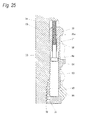
- a worker causes the hexagon socket head cap bolt 66 of the replaceable unit 60 to be screwed into the screw hole 86a of the through-hole 86 of the replaceable unit 60, thereby enabling the replaceable unit 60 to be detached from the main body 10. That is, as illustrated in Fig.
- the hexagon socket head cap bolt 66 of the replaceable unit 60 is screwed into the screw hole 86a of the through-hole 86 of the replaceable unit 60, and comes into contact with the main body 10 on the opposite side to the unit replacement opening 39 side via the through-hole 86. In this manner, the replaceable unit 60 is separated from the main body 10 on the opposite side to the unit replacement opening 39 side.
- This configuration enables the replaceable unit 60 to be reliably detached from the main body 10 regardless of whether or not the housing 30 is fixed so that the unit replacement opening 39 is located below in the vertical direction. Therefore, for example, the replaceable unit 60 can be reliably detached from the main body 10 while the housing 30 is attached to the arm 113 as it is.
- a new replaceable unit 60 is accommodated in the unit accommodation portion 34 of the housing 30 via the unit replacement opening 39 of the housing 30.
- the fitting portion 43 of the holder 40 of the main body 10 and the fitting portion 83 of the unit body 80 of the replaceable unit 60 are fitted to each other. In this manner, a positional relationship of the gap forming member 20 of the main body 10 with the white LED 72 and the RGB sensor 73 of the replaceable unit 60 becomes a predetermined positional relationship.
- the housing cap 50 is rotated with respect to the housing 30 by using a jig which is inserted into the jig contact portion 51.
- the male screw 52 of the housing cap 50 is screwed into the female screw 35 of the housing 30, thereby fixing the housing cap 50 to the housing 30.
- the new replaceable unit 60 is fixed to the main body 10 by using the hexagon socket head cap bolt 11.
- the lubricant deterioration sensor 139b Next, an operation of the lubricant deterioration sensor 139b will be described.
- the lubricant deterioration sensor 139b will be described, but the lubricant deterioration sensors other than the lubricant deterioration sensor 139b, such as the lubricant deterioration sensors 137a, 137b, and 139a, have the same configuration.
- the lubricant deterioration sensor 139b causes the white LED 72 to emit white light by using electric power supplied from the button-type battery 74.
- the lubricant deterioration sensor 139b outputs luminous energy of each RGB color of the light received by the RGB sensor 73 to an external device as an electric signal, by radio using a communication device on the circuit board 71.
- the lubricant deterioration sensor 139b may include a separately mounted sensor in addition to the RGB sensor 73.
- the lubricant deterioration sensor 139b can also output the temperature detected by the temperature sensor to the external device as the electric signal, by radio using the communication device on the circuit board 71.
- the lubricant deterioration sensor 139b will be described, but the lubricant deterioration sensors other than the lubricant deterioration sensor 139b, such as the lubricant deterioration sensors 137a, 137b, and 139a, have the same configuration.
- the external device of the lubricant deterioration sensor 139b can identify types and quantities of contaminant contained in the lubricant 131 a of the reducer 131, based on a color detected by the RGB sensor 73. That is, the lubricant deterioration sensor 139b can detect a deterioration degree of the lubricant 131 a by detecting the color of the contaminant contained in the lubricant 131a.
- Fig. 26 is a view illustrating an example of a relationship between the direction of the opening 20b of the oil gap 20a with respect to flow of the lubricant 131 a and a color difference ⁇ E of a color detected by the RGB sensor 73 with respect to the black color.
- Fig. 27(a) is a view illustrating a state where the direction of the opening 20b of the oil gap 20a with respect to the flow of the lubricant 131a represents 0°.
- Fig. 27(b) is a view illustrating a state where the direction of the opening 20b of the oil gap 20a with respect to the flow of the lubricant 131a represents 45°.
- Fig. 27(c) is a view illustrating a state where the direction of the opening 20b of the oil gap 20a with respect to the flow of the lubricant 131a represents 90°.
- the color difference ⁇ E of the color detected by the RGB sensor 73 with respect to the black color can be calculated by using each RGB value of the color detected by the RGB sensor 73 and based on the following equation expressed in Expression 1.
- ⁇ E R 2 + G 2 + B 2
- the term "static state" means a time when the flow of the lubricant 131 a is stopped.
- the direction of the opening 20b of the oil gap 20a with respect to the flow of the lubricant 131 a does not affect the color difference ⁇ E of the color detected by the RGB sensor 73 with respect to the black color.
- the color difference ⁇ E of the color detected by the RGB sensor 73 with respect to the black color "static state" becomes a determination criteria for determining the relationship between the direction of the opening 20b of the oil gap 20a with respect to the flow of the lubricant 131a and the color difference ⁇ E of the color detected by the RGB sensor 73 with respect to the black color.
- 36 rpm and 45 rpm represent that a rotation speed of the arm 113 with respect to the arm 112 is indicated by using the number of revolutions per one minute. Since the lubricant deterioration sensor 139b is attached to the arm 113, the rotation of the arm 113 with respect to the arm 112 causes the lubricant deterioration sensor 139b to move inside the lubricant 131 a. That is, 36 rpm and 45 rpm indirectly represent the speed of the flow of the lubricant 131 a with respect to the lubricant deterioration sensor 139b.
- arrows other than an arrow representing the oil gap 20a indicate the flow of the lubricant 131 a.
- Accuracy in detecting the deterioration of the lubricant 131a can be determined by the color difference ⁇ E of the color detected by the RGB sensor 73 with respect to the black color. That is, in Fig. 26 , the accuracy in detecting the deterioration of the lubricant 131 a becomes poor when the number of revolutions of the arm 113 with respect to the arm 112 is 45 rpm, which is a case where the direction of the opening 20b of the oil gap 20a with respect to the flow of the lubricant 131 a is 0° and 45°. As described above, in some cases, the accuracy in detecting the deterioration of the lubricant 131a becomes poor due to the direction of the opening 20b of the oil gap 20a with respect to the flow of the lubricant 131 a.
- the direction of the opening 20b of the oil gap 20a can be adjusted.
- the hexagon socket head cap bolt 11 is unfastened by using a jig inserted into the jig contact portion 11 a so that the replaceable unit 60 can be rotated with respect to the main body 10.
- the replaceable unit 60 is rotated with respect to the housing 30 by using the jig inserted into the jig contact portion 91. If the replaceable unit 60 is rotated with respect to the housing 30, the fitting portion 83 of the unit body 80 of the replaceable unit 60 and the holder 40 to which the fitting portion 43 is fitted are rotated with respect to the housing 30. If the holder 40 is rotated with respect to the housing 30, the oil gap 20a formed in the gap forming member 20 supported by the holder 40 is rotated with respect to the housing 30. That is, the direction of the opening 20b of the oil gap 20a is changed by the rotation of the replaceable unit 60 with respect to the housing 30.
- the hexagon socket head cap bolt 11 is unfastened by using the jig which is inserted into the jig contact portion 11 a so that the replaceable unit 60 cannot be rotated with respect to the housing 30.
- each lubricant deterioration sensor such as the lubricant deterioration sensor 139b causes the RGB sensor 73 to detect a color with respect to light which is not absorbed by the contaminant contained in the lubricant 131 a in the oil gap 20a, out of the white light emitted by the white LED 72. Accordingly, it is possible to immediately detect the color of the contaminant contained in the lubricant 131a of the reducer 131. That is, each lubricant deterioration sensor enables an external device such as a computer to immediately identify types and quantities of the contaminant contained in the lubricant 131a of the reducer 131, based on the color detected by the RGB sensor 73.
- Each lubricant deterioration sensor may be configured so that an electronic component which identifies the types and quantities of the contaminant contained in the lubricant, based on the color detected by the RGB sensor 73, is included in the electronic component group 70.
- each lubricant deterioration sensor for the industrial robot 100 enables the external device such as the computer to immediately identify the types and quantities of the contaminant contained in the lubricant 131 a of the reducer 131, based on the color detected by the RGB sensor 73. Accordingly, the industrial robot 100 and each reducer of the industrial robot 100 can immediately predict the failure.
- each lubricant deterioration sensor such as the lubricant deterioration sensor 139b
- a consumable component such as the white LED 72 is included in the replaceable unit 60. Accordingly, it is possible to lengthen the life span by replacing the replaceable unit 60 from the main body 10.
- each lubricant deterioration sensor such as the lubricant deterioration sensor 139b
- the consumable component such as the white LED 72 is unitized as the replaceable unit 60. Accordingly, the consumable component such as the white LED 72 is replaced by replacing the replaceable unit 60 from the main body 10. Therefore, each lubricant deterioration sensor such as the lubricant deterioration sensor 139b enables not only a manufacturer of the lubricant deterioration sensor but also a user of the lubricant deterioration sensor to easily replace the consumable component such as the white LED 72.
- the hexagon socket head cap bolt 66 of the replaceable unit 60 is screwed into the screw hole 86a of the through-hole 86 of the replaceable unit 60 from the unit replacement opening 39 side of the main body 10, and comes into contact with the main body 10 on the opposite side to the unit replacement opening 39. In this manner, the replaceable unit 60 is separated from the main body 10 on the opposite side to the unit replacement opening 39. That is, in each lubricant deterioration sensor such as the lubricant deterioration sensor 139b, the replaceable unit 60 is easily detached from the main body 10 in such a way that the hexagon socket head cap bolt 66 of the replaceable unit 60 is screwed into the screw hole 86a of the through-hole 86 of the replaceable unit 60. Therefore, each lubricant deterioration sensor such as the lubricant deterioration sensor 139b can facilitate the replacement of the replaceable unit 60 from the main body 10.
- each lubricant deterioration sensor such as the lubricant deterioration sensor 139b
- the replaceable unit 60 includes the hexagon socket head cap bolt 66 which is to be screwed into the screw hole 86a of the through-hole 86 so that the replaceable unit 60 is detached from the main body 10. Accordingly, it is not necessary to separately prepare a screw to be screwed into the screw hole 86a of the through-hole 86 in order to detach the replaceable unit 60 from the main body 10. Therefore, each lubricant deterioration sensor such as the lubricant deterioration sensor 139b can facilitate the replacement of the replaceable unit 60 from the main body 10.
- the button-type battery 74 whose life span is shorter than the life span of the white LED 72 can be replaced from the unit body 80. Accordingly, it is possible to lengthen the life span by replacing the button-type battery 74 from the unit body 80.
- the button-type battery 74 with the replaceable unit 60 can also be replaced from the main body 10. Accordingly, the button-type battery 74 may be configured so as not to be replaceable from the unit body 80.
- the white LED 72 and the RGB sensor 73 are arranged on the opposite side to the battery replacement opening 87 in the cover 64 of the replaceable unit 60.
- the button-type battery 74 is arranged on the battery replacement opening 87 side in the cover 64. That is, in each lubricant deterioration sensor such as the lubricant deterioration sensor 139b, when the button-type battery 74 is replaced from the unit body 80, as illustrated in Fig. 16 , the cover 64 hides the white LED 72 and the RGB sensor 73 from a view of a worker.
- each lubricant deterioration sensor such as the lubricant deterioration sensor 139b
- when the button-type battery 74 is replaced from the unit body 80 it is possible to minimize a possibility that the worker may touch the white LED 72 and the RGB sensor 73. That is, each lubricant deterioration sensor such as the lubricant deterioration sensor 139b can facilitate the worker's replacement of the button-type battery 74.
- the replaceable battery according to the present invention is the button-type battery in the present embodiment.
- a battery other than the button-type battery such as a lithium-ion battery, may be employed.
- each lubricant deterioration sensor such as the lubricant deterioration sensor 139b
- the holder 40 is arranged inside the screw 31 so as to be separate from the screw 31 so that a portion of the optical path 72a is arranged inside the screw 31. Accordingly, for example, when a screw hole such as the screw hole 113a is formed to be smaller than the screw 31, even when the screw 31 of the housing 30 is deformed inward by externally coming into contact with a screw hole of the machine body, such as the screw hole 113a of the arm 113, the deformation of the screw 31 is less likely to be transferred to the holder 40 arranged to be separate from the screw 31, and the optical path 72a is less likely to be changed due to the deformation of the holder 40.
- each lubricant deterioration sensor such as the lubricant deterioration sensor 139b, it is possible to suppress that accuracy in detecting the deterioration of the lubricant 131 a in the machine body becomes poor when each lubricant deterioration sensor is fixed to the machine body by using the screw 31.
- each lubricant deterioration sensor such as the lubricant deterioration sensor 139b
- the screw 31 comes into contact with the machine body by being screwed into the screw hole of th machine body. Consequently, the screw 31 is likely to be deformed inward. Therefore, there is a considerably advantageous effect in that it is possible to suppress that the accuracy in detecting the deterioration of the lubricant in the machine body becomes poor when the screw 31 is fixed to the machine body.
- a portion of the screw 31 illustrated in Fig. 3 may simply serve as a contact portion which externally comes into contact with the machine body.
- the portion of the screw 31 may be a simple cylindrical portion having no screw.
- the contact portion comes into contact with the machine body by being inserted into the hole of the machine body. Consequently, the contact portion is likely to be deformed inward.
- the lubricant 131a is obtained by adding various types of additive thereto, which include a friction reducing agent such as organic molybdenum (Mo) of molybdenum dithiocarbamate (MoDTC) or molybdenum dithiocarbamate (MoDTP) for decreasing friction on a friction surface, an extreme-pressure additive such as an SP-based additive for improving extreme-pressure lubricity representing the performance for suppressing the seizure of the friction surface, and a dispersing agent such as calcium sulfonate for suppressing generation and adhesion of sludge.
- a friction reducing agent such as organic molybdenum (Mo) of molybdenum dithiocarbamate (MoDTC) or molybdenum dithiocarbamate (MoDTP) for decreasing friction on a friction surface
- an extreme-pressure additive such as an SP-based additive for improving extreme-pressure lubricity representing the performance for suppressing the seizure of the friction surface
- each lubricant deterioration sensor can identify not only an quantity of ion powder contained in the lubricant 131 a but also a deterioration degree of base oil, and can identify an increase in the contaminant such as the sludge which may be caused by a decrease in various types of additive added to the lubricant 131 a. Therefore, the industrial robot 100 and each reducer of the industrial robot 100 can improve the accuracy in predicting the failure as compared with a technique where the failure of the reducer is predicted based on only the density of the iron powder.
- the housing 30 rotatably supports the replaceable unit 60 so as to change the direction of the opening 20b of the oil gap 20a when the replaceable unit 60 is rotated. Accordingly, it is possible to adjust the direction of the opening 20b of the oil gap 20a when the housing 30 is fixed to the industrial robot 100, so as to improve the accuracy in detecting the deterioration of the lubricant 131 a of the industrial robot 100 when the housing 30 is fixed to the industrial robot 100. Therefore, the industrial robot 100 and each reducer of the industrial robot 100 can predict the failure very accurately.
- the replaceable unit 60 includes the jig contact portion 91 serving as a portion in which the drive force of the rotation with respect to the housing 30 is received from the outside by using the contact force, at a position where the lubricant 131 a is not touched when the housing 30 is fixed to the industrial robot 100. Therefore, in each lubricant deterioration sensor, it is possible to adjust the direction of the opening 20b of the oil gap 20a when the housing 30 is fixed to the industrial robot 100, so as to improve the accuracy in detecting the deterioration of the lubricant 131 a of the industrial robot 100 after the housing 30 is fixed to the industrial robot 100.
- the hexagon socket head cap bolt 11 which prevents the rotation of the replaceable unit 60 with respect to the housing 30 by coming into contact with both the housing 30 and the replaceable unit 60 includes the jig contact portion 11a serving as a portion in which the drive force for coming into contact with both the housing 30 and the replaceable unit 60 is received from the outside by using the contact force, at a position where the lubricant 131 a is not touched when the housing 30 is fixed to the industrial robot 100.
- each lubricant deterioration sensor is the white LED whose light emitting element emits the white light. Accordingly, for example, as compared to a configuration in which the light emitting element is a lamp other than an LED, each lubricant deterioration sensor can be downsized. Therefore, the industrial robot 100 and each reducer of the industrial robot 100 can be downsized.
- the light emitting element according to the present invention may be any configuration element other than an LED.
- the light emitting element may be a lamp other than an LED.
- the light emitting element may include a red LED or a red light lamp other than an LED, a green LED or a green light lamp other than an LED, or a blue LED or a blue light lamp other than an LED.
- the configuration element may emit the white light by combining each color light emitted from LEDs or the lamps other than an LED.
- each lubricant deterioration sensor is configured so that the light reflection surfaces 21 b and 22b which bend the optical path 72a are formed in the gap forming member 20. Accordingly, as compared to a configuration in which the optical path 72a is formed linearly from the white LED 72 to the RGB sensor 73, the overall lubricant deterioration sensor can be downsized by arranging the white LED 72 and the RGB sensor 73 to be close to each other.
- the gap forming member 20 has not only a function of forming the oil gap 20a but also a function of bending the optical path 72a.
- the industrial robot 100 and each reducer of the industrial robot 100 can be downsized, and can reduce the number of components therein.
- each lubricant deterioration sensor the gap forming member 20 is configured to have the two right-angle prisms 21 and 22 respectively having the light reflection surfaces 21 b and 22b which bend the optical path 72a by 90 degrees.
- Each lubricant deterioration sensor is configured so that the oil gap 20a is formed between the two right-angle prisms 21 and 22 by causing the light reflection surfaces 21 b and 22b of the two right-angle prisms 21 and 22 to bend the optical path 72a by 180 degrees. Accordingly, each lubricant deterioration sensor can be downsized using a simple configuration having the reduced number of components. Therefore, the industrial robot 100 and each reducer of the industrial robot 100 can be downsized using the simple configuration having the reduced number of components.
- each lubricant deterioration sensor includes the holder 40 which surrounds at least a portion of the optical path 72a, and is configured so that the surface of the holder 40 is subjected to treatment for preventing the light reflection. Accordingly, it is possible to prevent the RGB sensor 73 from receiving unnecessarily reflected light. For this reason, as compared to a configuration in which the RGB sensor 73 receives the unnecessarily reflected light, it is possible to improve the accuracy in detecting the color of the contaminant contained in the lubricant 131 a. Therefore, the industrial robot 100 and each reducer of the industrial robot 100 can improve the accuracy in predicting the failure.
- each lubricant deterioration sensor surfaces having the oil gap 20a within the gap forming member 20, that is, the light emitting surface 21c of the right-angle prism 21 and the light incident surface 22a of the right-angle prism 22 may be subjected to oil repelling treatment.
- the lubricant 131 a is allowed to easily flow through the oil gap 20a.
- the industrial robot 100 and each reducer of the industrial robot 100 can improve the accuracy in predicting the failure.
- the accuracy in predicting the failure of the reducer can be improved by combinedly using the lubricant deterioration sensor according to the present invention, a temperatures sensor for measuring the temperature of the lubricant, and a monitoring mechanism for monitoring a current value of a motor.
- the right-angle prisms 21 and 22 of the gap forming member 20 are made of glass in the present embodiment.
- materials other than the glass such as silicone resin, may be used.
- a configuration can be made so that the dirt becomes less likely to adhere to the surface having the oil gap 20a by forming the right-angle prisms 21 and 22 using the silicone resin.
- the gap forming member 20 is configured to have the two right-angle prisms 21 and 22 in the present embodiment, but may be configured to have three or more prisms.
- the white LED 72 and the RGB sensor 73 may be arranged unlike in the arrangement described in the present embodiment.
- the optical path 72a may be formed linearly from the white LED 72 to the RGB sensor 73.
- the optical path 72a may be bent by a configuration excluding the right-angle prism.
- each lubricant deterioration sensor employs radio communication using the incorporated communication device in the present embodiment.
- wired communication may be employed.
- each lubricant deterioration sensor employs the incorporated battery in the present embodiment.
- a cable for electrically connecting the external power source and the lubricant deterioration sensor to each other may be employed.
- a position for installing each lubricant deterioration sensor is not limited to the position illustrated in the present embodiment, but it is preferable to appropriately set the position to match an operating purpose of the industrial robot.
- the machine according to the present invention is the reducer for the industrial robot or the industrial robot, but may be a machine other than the reducer for the industrial robot or the industrial robot.
- Japanese Patent Application Japanese Patent Application No. 2012-108392 filed on May 10, 2012 , the content of which is incorporated herein by reference.
- a lubricant deterioration sensor which can immediately identify types and quantities of contaminant contained in lubricant of a machine.
Landscapes
- Engineering & Computer Science (AREA)
- Chemical & Material Sciences (AREA)
- Physics & Mathematics (AREA)
- Life Sciences & Earth Sciences (AREA)
- Health & Medical Sciences (AREA)
- Pathology (AREA)
- General Health & Medical Sciences (AREA)
- Mechanical Engineering (AREA)
- Immunology (AREA)
- General Physics & Mathematics (AREA)
- Analytical Chemistry (AREA)
- Biochemistry (AREA)
- General Engineering & Computer Science (AREA)
- Robotics (AREA)
- General Chemical & Material Sciences (AREA)
- Medicinal Chemistry (AREA)
- Food Science & Technology (AREA)
- Oil, Petroleum & Natural Gas (AREA)
- Spectroscopy & Molecular Physics (AREA)
- Chemical Kinetics & Catalysis (AREA)
- Investigating Or Analysing Materials By Optical Means (AREA)
- Manipulator (AREA)
Abstract
Description
- The present invention relates to a lubricant deterioration sensor for detecting deterioration of lubricant of a machine.
- In the related art, as a lubricant deterioration sensor for detecting deterioration of lubricant of a machine, an oil deterioration degree sensor has been known. In this sensor, an oil entering gap portion which the lubricant is allowed to enter is formed on an optical path from an infrared a light emitting diode (LED) to a photo diode. Then, a light absorption quantity of the lubricant inside the oil entering gap portion with respect to light emitted from the infrared LED is measured according to a light reception quantity of the photo diode, thereby determining a deterioration degree of the lubricant related to the measured light absorption quantity (for example, refer to PTL 1 and PTL 2).
- However, the oil deterioration degree sensor described in PTL 1 and PTL 2 can measure the density of insoluble content contained in the lubricant as the deterioration degree of the lubricant, but has a problem in that types of contaminant contained in the lubricant cannot be specified.
- As a technique of identifying the types of contaminant contained in the lubricant, a technique has been known in which an LED emits light toward a membrane filter which has filtered the lubricant. Then, a light receiving element converts reflection light from the contaminant on the membrane filter into an RGB digital value, thereby identifying the types of contaminant contained in the lubricant, based on the converted RGB digital value (for example, refer to NPL 1 and NPL 2).
-
- [PTL 1]
JP-A-7-146233 - [PTL 2]
JP-A-10-104160 - [NPL 1] Tomohiko Yamaguchi and four others, "METHOD OF DISCRIMINATING HUE OF CONTAMINANT CONTAINED IN LUBRICANT", Fukui University, Faculty of Engineering, Research Report, March 2003,
- [NPL 2] Tomomi Honda, "TECHNOLOGY FOR DIAGNOSING AND INSPECTING DETERIORATION OF LUBRICANT", Journal of Japan Society for Precision Engineering, 2009,
- In the technique disclosed in NPL 1 and NPL 2, it is necessary to drain lubricant from a machine and to filter the lubricant using a membrane filter. Consequently, there is a problem in that the technique lacks immediacy.
- An object of the present invention is to provide a lubricant deterioration sensor which can immediately identify types and quantities of contaminant contained in lubricant of a machine.
- According to an advantageous aspect of the present invention, there is provided a lubricant deterioration sensor which is installed in a machine body so as to detect deterioration of lubricant in the machine body, the sensor including:
- a main body that is configured to be fixed to the machine body; and
- a replaceable unit that can be replaced from the main body,
- wherein the main body includes a gap forming member having an oil gap which the lubricant is allowed to enter,
- wherein the replaceable unit includes a light emitting element configured to emit light and a color light receiving element configured to detect a color of the received light,
- wherein the gap forming member is configured to allow the light emitted by the light emitting element to pass therethrough,
- wherein the oil gap is arranged on an optical path formed from the light emitting element to the color light receiving element,
- wherein the main body has a first fitting portion, and the replaceable unit has a second fitting portion, and
- wherein the first fitting portion and the second fitting portion are fitted to each other in a state where a positional relationship between the gap forming member and the light emitting element and the color light receiving element becomes a predetermined positional relationship.
- The main body may have a unit replacement opening through which the replaceable unit is allowed to pass when the replaceable unit is detached from the main body. The replaceable unit may have a through-hole which causes the unit replacement opening side and an opposite side to the unit replacement opening to communicate with each other. At least a portion of the through-hole may be a screw hole.
- The replaceable unit may include a detaching screw which is configured to come into contact with the main body on the opposite side to the unit replacement opening via the through-hole screwed into the screw hole from the unit replacement opening side so that the replaceable unit is separated from the main body on the opposite side to the unit replacement opening.
- The replaceable unit may include a unit body which supports the light emitting element and the color light receiving element and a replaceable battery which can be replaced from the unit body. The replaceable battery may have a life span which is longer than a life span of the light emitting element, and may supply electric power to at least the light emitting element.
- The replaceable unit may include a cover which covers the light emitting element and the color light receiving element. The unit body may have a battery replacement opening through which the replaceable battery is allowed to pass when the replaceable battery is detached from the unit body. The light emitting element and the color light receiving element may be arranged on an opposite side to the battery replacement opening in the cover. The replaceable battery may be arranged on the battery replacement opening side in the cover.
- The main body may include a support member which supports the gap forming member and a fixing member which is configured to fix the machine body. The first fitting portion may be disposed in the support member, and the fixing member may rotatably support the support member and the replaceable unit so that an opening direction of the oil gap varies when the support member and the replaceable unit are rotated.
- A machine according to the present invention includes the above-described lubricant deterioration sensor and the machine body.
- The machine may be a reducer for an industrial robot, and the machine body may be a reducer body.
- The machine may be an industrial robot, and the machine body may include an arm and a reducer which is used for a joint of the arm. The lubricant may be lubricant of the reducer.
- In the lubricant deterioration sensor according to the present invention, the color light receiving element detects a color with respect to the light having a wavelength which is not absorbed by the contaminant such as ion powder contained in the lubricant in the oil gap, from the light emitted by the light emitting element. Accordingly, the color of the contaminant contained in the lubricant of the machine body can be detected immediately. That is, the lubricant deterioration sensor according to present invention can immediately identify types and quantities of the contaminant contained in the lubricant of the machine body, based on the color detected by the color light receiving element. In addition, in the lubricant deterioration sensor according to the present invention, a consumable component such as the light emitting element is provided for the replaceable unit. Accordingly, the replaceable unit is replaced from the main body, thereby enabling the life span to be lengthened.
- In the lubricant deterioration sensor according to the present invention, the screw comes into contact with the main body on the opposite side to the unit replacement opening via the through-hole screwed into the screw hole of the through-hole from the unit replacement opening side so that the replaceable unit is separated from the main body on the opposite side to the unit replacement opening. Accordingly, the replaceable unit can be easily detached from the main body. Therefore, the lubricant deterioration sensor according to the present invention can facilitate replacement of the replaceable unit from the main body.
- In the lubricant deterioration sensor according to the present invention, it is not necessary to separately prepare the screw which is screwed into the screw hole of the through-hole in order to detach the replaceable unit from the main body. Accordingly, the lubricant deterioration sensor can facilitate the replacement of the replaceable unit from the main body.
- In the lubricant deterioration sensor according to the present invention, the replaceable battery whose life span is shorter than the life span of the light emitting element can be replaced from the unit body. Accordingly, it is possible to lengthen the life span by exchanging the replaceable battery from the unit body.
- In the lubricant deterioration sensor according to the present invention, the cover hides the light emitting element and the color light receiving element from a view of a worker when the replaceable battery is replaced from the unit body. Accordingly, the lubricant deterioration sensor can facilitate the worker's replacement of the replaceable battery.
- In the lubricant deterioration sensor according to the present invention, the opening direction of the oil gap when the fixing member is fixed to the machine body can be adjusted so as to improve the detection accuracy of the deterioration of the lubricant in the machine body when the fixing member is fixed to the machine body.
- In the machine according to the present invention, the lubricant deterioration sensor can immediately identify the types and quantities of the contaminant contained in the lubricant in the machine body. Accordingly, it is possible to immediately predict a failure. In addition, in the machine according to the present invention, it is possible to lengthen the life span of the lubricant deterioration sensor which can immediately identify the types and quantities of the contaminant contained in the lubricant. Accordingly, it is possible to maintain accuracy in immediately predicting the failure for a longer period of time.
- In the industrial robot, locus accuracy of the arm greatly depends on performance of the reducer used for the joint. Therefore, it is important to properly replace the reducer for the industrial robot when the performance becomes poor. However, when the reducer for the industrial robot is replaced, it is inevitable that the industrial robot including the reducer or an industrial robot-installed production line is to be stopped. For this reason, in order to accurately predict the time to replace the reducer for the industrial robot, it is very important that failure of the reducer for the industrial robot is predicted properly. Therefore, the reducer for the industrial robot according to the present invention provides an advantageous effect that the accuracy in immediately predicting the failure can be maintained for a longer period of time.
- As described above, it is very important that the failure of the reducer for the industrial robot is predicted properly. Therefore, the industrial robot according to the present invention provides an advantageous effect in that the accuracy in immediately predicting the failure can be maintained for a longer period of time.
- The lubricant deterioration sensor according to the present invention can immediately identify the types and quantities of the contaminant contained in the lubricant of the machine.
-
-
Fig. 1 is a side view of an industrial robot according to an embodiment of the present invention. -
Fig. 2 is a cross-sectional view of a joint of the industrial robot illustrated inFig. 1 . -
Fig. 3 is a front view of a lubricant deterioration sensor illustrated inFig. 2 . -
Fig. 4 is a front sectional view of the lubricant deterioration sensor illustrated inFig. 3 in a state where the lubricant deterioration sensor is attached to an arm. -
Fig. 5 is a view in which the lubricant deterioration sensor illustrated inFig. 3 is partially broken. -
Fig. 6(a) is a plan view of the lubricant deterioration sensor illustrated inFig. 3 .Fig. 6(b) is a bottom view of the lubricant deterioration sensor illustrated inFig. 3 . -
Fig. 7(a) is a plan view of a housing illustrated inFig. 3 .Fig. 7(b) is a front sectional view of the housing illustrated inFig. 3 . -
Fig. 8(a) is a side view of the housing illustrated inFig. 3 .Fig. 8(b) is a side sectional view of the housing illustrated inFig. 3 . -
Fig. 9(a) is a plan view of the housing illustrated inFig. 3 .Fig. 9(b) is a bottom view of the housing illustrated inFig. 3 . -
Fig. 10(a) is a front view of a holder illustrated inFig. 4 .Fig. 10(b) is a front sectional view of the holder illustrated inFig. 4 . -
Fig. 11 (a) is a side view of the holder illustrated inFig. 4 .Fig. 11 (b) is a side sectional view of the holder illustrated inFig. 4 . -
Fig. 12(a) is a plan view of the holder illustrated inFig. 4 .Fig. 12(b) is a bottom view of the holder illustrated inFig. 4 . -
Fig. 13 is a view illustrating an optical path formed from a white LED to an RGB sensor as illustrated inFig. 4 . -
Fig. 14(a) is a plan view of a housing cap illustrated inFig. 4 .Fig. 14(b) is a front sectional view of the housing cap illustrated inFig. 4 . -
Fig. 15(a) is a plan view of the housing cap illustrated inFig. 4 .Fig. 15(b) is a bottom view of the housing cap illustrated inFig. 4 . -
Fig. 16 is a plan view of a replaceable unit illustrated inFig. 4 when a button-type battery and a unit cap are detached therefrom. -
Fig. 17(a) is a front view of a unit body illustrated inFig. 4 .Fig. 17(b) is a front sectional view of the unit body illustrated inFig. 4 . -
Fig. 18(a) is a side view of the unit body illustrated inFig. 4 .Fig. 18(b) is a side sectional view of the unit body illustrated inFig. 4 . -
Fig. 19(a) is a plan view of the unit body illustrated inFig. 4 .Fig. 19(b) is a bottom view of the unit body illustrated inFig. 4 . -
Fig. 20 is a cross-sectional view taken along arrow I-I inFig. 19(a) . -
Fig. 21(a) is a plan view of a unit cap illustrated inFig. 4 .Fig. 21(b) is a bottom view of the unit cap illustrated inFig. 4 . -
Fig. 22(a) is a front view of the unit cap illustrated inFig. 4 .Fig. 22(b) is a cross-sectional view taken along arrow II-II inFig. 21 (a) . -
Fig. 23 is a view illustrating a state where a button-type battery illustrated inFig. 4 is detached therefrom. -
Fig. 24 is a view illustrating a state where a replaceable unit illustrated inFig. 4 is detached therefrom. -
Fig. 25 is a view illustrating a state where a hexagon socket head cap bolt of the replaceable unit illustrated inFig. 4 is screwed so that the replaceable unit is separated from a main body. -
Fig. 26 is a view illustrating an example of a relationship between an opening direction of an oil gap illustrated inFig. 3 with respect to lubricant flow and a color difference ΔE of a color detected by an RGB sensor with respect to the black color. -
Fig. 27(a) is a view illustrating a state where the opening direction of the oil gap illustrated inFig. 3 with respect to the lubricant flow represents 0°.Fig. 27(b) is a view illustrating a state where the opening direction of the oil gap illustrated inFig. 3 with respect to the lubricant flow represents 45°.Fig. 27(c) is a view illustrating a state where the opening direction of the oil gap illustrated inFig. 3 with respect to the lubricant flow represents 90°. - Hereinafter, an embodiment of the present invention will be described with reference to the drawings.
- First, a configuration of an industrial robot serving as a machine according to the present embodiment will be described.
-
Fig. 1 is a side view of anindustrial robot 100 according to the present embodiment. - As illustrated in
Fig. 1 , theindustrial robot 100 includes anattachment section 111 attached to aninstallation section 900 such as a floor and a ceiling,arms 112 to 116, a joint 120 connecting theattachment section 111 and thearm 112, a joint 130 connecting thearm 112 and thearm 113, a joint 140 connecting thearm 113 and thearm 114, a joint 150 connecting thearm 114 and thearm 115, a joint 160 connecting thearm 115 and thearm 116, and a joint 170 connecting thearm 116 and a hand (not illustrated). - A part in which lubricant such as
lubricant 131 a (to be described later) and a lubricant deterioration sensor such aslubricant deterioration sensors industrial robot 100 configures a machine body according to the present invention when theindustrial robot 100 is a machine according to the present invention. -
Fig. 2 is a cross-sectional view of the joint 130. Hereinafter, the joint 130 will be described, but thejoints - As illustrated in
Fig. 2 , the joint 130 includes areducer 131 which is a reducer for the industrial robot connecting thearm 112 and thearm 113, amotor 138 fixed to thearm 112 by abolt 138a, and thelubricant deterioration sensor 139a and thelubricant deterioration sensor 139b which are used for detecting deterioration oflubricant 131 a which decreases friction generated in a movable portion of thereducer 131. - The
reducer 131 includes areducer body 132, and thelubricant deterioration sensor 137a and thelubricant deterioration sensor 137b which are used for detecting the deterioration of thelubricant 131 a in thereducer body 132. Thereducer body 132 configures a machine body according to the present invention when thereducer 131 is the machine according to the present invention. - The
reducer body 132 includes acase 133 fixed to thearm 112 by abolt 133a, asupport body 134 fixed to thearm 113 by abolt 134a, a gear 135a fixed to an output shaft of themotor 138, threegears 135b (only one is illustrated inFig. 2 ) which are arranged around the central axis of thereducer 131 at equal intervals and mesh with the gear 135a, three crankshafts 135c (only one is illustrated inFig. 2 ) which are arranged around the central axis of thereducer 131 at equal intervals and are fixed to thegears 135b, and twoexternal gears 136 which mesh with an internal gear disposed in thecase 133. - The
support body 134 is rotatably supported by thecase 133 via abearing 133b. Aseal member 133c for preventing leakage of thelubricant 131a is disposed between thecase 133 and thesupport body 134. - The
crank shaft 135c is rotatably supported by thesupport body 134 via abearing 134b, and is rotatably supported by theexternal gear 136 via abearing 136a. - The
lubricant deterioration sensor 137a and thelubricant deterioration sensor 137b are fixed to thecase 133. Thelubricant deterioration sensor 139a is fixed to thearm 112. Thelubricant deterioration sensor 139b is fixed to thearm 113. -
Fig. 3 is a front view of thelubricant deterioration sensor 139b.Fig. 4 is a front sectional view of thelubricant deterioration sensor 139b in a state where thelubricant deterioration sensor 139b is attached to thearm 113.Fig. 5 is a view in which thelubricant deterioration sensor 139b is partially broken.Fig. 6(a) is a plan view of thelubricant deterioration sensor 139b.Fig. 6(b) is a bottom view of thelubricant deterioration sensor 139b. Hereinafter, thelubricant deterioration sensor 139b will be described, but the lubricant deterioration sensors other than thelubricant deterioration sensor 139b, such as thelubricant deterioration sensors - As illustrated in
Figs. 3 to 6(b) , thelubricant deterioration sensor 139b includes thearm 113 of theindustrial robot 100, that is, themain body 10 fixed to the machine body, and areplaceable unit 60 which can be replaced from themain body 10. - The
main body 10 includes agap forming member 20 having anoil gap 20a serving as a gap which thelubricant 131a is allowed to enter, an aluminum alloy-madehousing 30 serving as a fixing member to be fixed to thearm 113, an aluminum alloy-madeholder 40 serving as a support member for supporting thegap forming member 20, and an aluminum alloy-madehousing cap 50 which accommodates thereplaceable unit 60 with thehousing 30. Themain body 10 includes a hexagon sockethead cap bolt 11 which prevents rotation of thereplaceable unit 60 with respect to thehousing 30 by coming into contact with both thehousing 30 and thereplaceable unit 60, an O-ring 12 which prevents thelubricant 131 a from leaking out from a portion between thehousing 30 and thearm 113, an O-ring 13 which is arranged between thehousing 30 and theholder 40, an O-ring 14 which is arranged between thehousing 30 and thehousing cap 50, and an O-ring 15 which is arranged between thehousing cap 50 and thereplaceable unit 60. - The hexagon socket
head cap bolt 11 includes ajig contact portion 11a which comes into contact with a jig such as a hexagon wrench. Thejig contact portion 11 a is a portion in which a drive force for coming into contact with both thehousing 30 and thereplaceable unit 60 is received from the outside by using a contact force. Thejig contact portion 11 a is arranged at a position where thelubricant 131a is not touched when thehousing 30 is fixed to thearm 113. - The
replaceable unit 60 includes anelectronic component group 70, an aluminum alloy-madeunit body 80 which supports theelectronic component group 70, and an aluminum alloy-madeunit cap 90 which accommodates theelectronic component group 70 with theunit body 80. Thereplaceable unit 60 includes a hexagon sockethead cap bolt 61 which fixes theunit body 80 and theunit cap 90, aspacer 62 which is arranged between a circuit board 71 (to be described later) and theunit body 80, aspacer 63 which is arranged on an opposite side to thespacer 62 in thecircuit board 71, an aluminum alloy-madecover 64 which is arranged on an opposite side to thecircuit board 71 in thespacer 63, a hexagon sockethead cap bolt 65 which fixes thespacer 62, thecircuit board 71, thespacer 63, and thecover 64 to theunit body 80, and a hexagon sockethead cap bolt 66 serving as a detaching screw for detaching thereplaceable unit 60 from themain body 10. - The
gap forming member 20 is configured to have two glass-made right-angle prisms oil gap 20a is formed between the two right-angle prisms - The
electronic component group 70 includes thecircuit board 71, awhite LED 72 mounted on thecircuit board 71, anRGB sensor 73 mounted on thecircuit board 71, a button-type battery 74 which supplies electric power to each electronic component on thecircuit board 71, such as thewhite LED 72 and theRGB sensor 73, andterminals type battery 74 and thecircuit board 71 to each other. In addition to thewhite LED 72 and theRGB sensor 73, multiple electronic components such as a communication device which performs communication with an external device of thelubricant deterioration sensor 139b are mounted on thecircuit board 71. - The button-
type battery 74 can be replaced from theunit body 80, and configures a replaceable battery according to the present invention. The button-type battery 74 has a life span shorter than a life span of thewhite LED 72. -
Fig. 7(a) is a front view of thehousing 30.Fig. 7(b) is a front sectional view of thehousing 30.Fig. 8(a) is a side view of thehousing 30.Fig. 8(b) is a side sectional view of thehousing 30.Fig. 9(a) is a plan view of thehousing 30.Fig. 9(b) is a bottom view of thehousing 30. - As illustrated in
Figs. 3 to 9(b) , thehousing 30 includes ascrew 31 fixed to ascrew hole 113a of thearm 113, ajig contact portion 32 to be gripped by a jig such as a spanner when thescrew 31 is rotated with respect to thescrew hole 113a of thearm 113, aholder accommodation portion 33 which accommodates theholder 40, and aunit accommodation portion 34 which accommodates thereplaceable unit 60. In addition, thehousing 30 has afemale screw 35 into which thehousing cap 50 is screwed, ascrew hole 36 into which the hexagon sockethead cap bolt 11 is screwed, agroove 37 into which the O-ring 12 is fitted, agroove 38 into which the O-ring 13 is fitted, and a unit replacement opening 39 through which thereplaceable unit 60 is allowed to pass when thereplaceable unit 60 is detached. - When the
lubricant deterioration sensor 139b is detached therefrom, thescrew hole 113a of thearm 113 may be used in supplying thelubricant 131 a to thereducer 131 and in discarding thelubricant 131 a from thereducer 131. -
Fig. 10(a) is a front view of theholder 40.Fig. 10(b) is a front sectional view of theholder 40.Fig. 11 (a) is a side view of theholder 40.Fig. 11 (b) is a side sectional view of theholder 40.Fig. 12(a) is a plan view of theholder 40.Fig. 12(b) is a bottom view of theholder 40.Fig. 13 is a view illustrating anoptical path 72a formed from thewhite LED 72 to theRGB sensor 73. - As illustrated in
Figs. 6(b) and10(a) to 13 , theholder 40 includes aprism accommodation portion 41 which accommodates the right-angle prism 21, aprism accommodation portion 42 which accommodates the right-angle prism 22, and a fitting portion 43 (first fitting portion) which is fitted to theunit body 80 in a state where a positional relationship of thegap forming member 20 with thewhite LED 72 and theRGB sensor 73 becomes a predetermined positional relationship. In addition, theholder 40 has ahole 44 which causes theprism accommodation portion 41 and thefitting portion 43 to communicate with each other, and ahole 45 which causes theprism accommodation portion 42 and thefitting portion 43 to communicate with each other. - The
holder 40 is arranged inside thescrew 31 so as to be separate from thescrew 31 so that a portion of theoptical path 72a is arranged inside thescrew 31 of thehousing 30. That is, agap 10a is formed between thescrew 31 of thehousing 30 and theholder 40. - The
prism accommodation portion 41 includes twowalls 41 a which interpose the right-angle prism 21 therebetween, and fixes the right-angle prism 21 on thewalls 41 a by using an adhesive. Theprism accommodation portion 42 includes twowalls 42a which interpose the right-angle prism 22 therebetween, and fixes the right-angle prism 22 on thewalls 42a by using an adhesive. - The
holder 40 surrounds at least a portion of theoptical path 72a formed from thewhite LED 72 to theRGB sensor 73 by using thehole 44, theprism accommodation portion 41, theprism accommodation portion 42, and thehole 45. For example, a surface of theholder 40 is subjected to treatment for preventing light reflection such as matt-finishing black alumite treatment. - As illustrated in
Fig. 13 , theoil gap 20a of thegap forming member 20 is arranged on theoptical path 72a formed from thewhite LED 72 to theRGB sensor 73. - The right-
angle prisms white LED 72 to pass therethrough. The right-angle prism 21 has alight incident surface 21a on which the light emitted by thewhite LED 72 is incident, a light reflection surface 21 b which reflects the light incident from thelight incident surface 21a and bends the light travelling direction by 90 degrees, and alight emitting surface 21c from which the light reflected on the light reflection surface 21 b is emitted. The right-angle prism 22 has alight incident surface 22a on which the light emitted from thelight emitting surface 21c of the right-angle prism 21 is incident, alight reflection surface 22b which reflects the light incident from thelight incident surface 22a and bends the light travelling direction by 90 degrees, and a light emitting surface 22c from which the light reflected on thelight reflection surface 22b is emitted. - The
light incident surface 21a, the light reflection surface 21 b, thelight emitting surface 21 c of the right-angle prism 21, and thelight incident surface 22a, thelight reflection surface 22b, and the light emitting surface 22c of the right-angle prism 22 are subjected to optical polishing. In addition, an aluminum vapor deposition film is formed on the light reflection surface 21 b of the right-angle prism 21 and thelight reflection surface 22b of the right-angle prism 22. Then, in order to protect the aluminum vapor deposition film whose rigidity and adhesion force are weak, a SiO2 film is further formed on the aluminum vapor deposition film. - The
optical path 72a is bent by 90 degrees on the light reflection surface 21 b of the right-angle prism 21 and is also bent by 90 degrees on thelight reflection surface 22b of the right-angle prism 22. That is, theoptical path 72a is bent by 180 degrees by thegap forming member 20. - In other words, a distance between the
light emitting surface 21c of the right-angle prism 21 and thelight incident surface 22a of the right-angle prism 22 is a length of theoil gap 20a. If the length of theoil gap 20a is too short, the contaminant contained in thelubricant 131a is less likely to properly flow through theoil gap 20a. Consequently, accuracy in detecting a color of the contaminant contained in thelubricant 131a becomes poor. In contrast, if the length of theoil gap 20a is too long, the light emitted from thewhite LED 72 is excessively absorbed by the contaminant contained in thelubricant 131 a inside theoil gap 20a, and is less likely to be transferred to theRGB sensor 73. Consequently, the accuracy in detecting a color of the contaminant contained in thelubricant 131a also becomes poor. Therefore, it is preferable to properly set the length of theoil gap 20a so as to improve the accuracy in detecting a color of the contaminant contained in thelubricant 131 a. For example, the length of theoil gap 20a is 1 mm. - The
white LED 72 is an electronic component which emits white light, and configures a light emitting element according to the present invention. For example, as thewhite LED 72, a product type of NSPW500GS-K1 manufactured by Nichia Corporation may be used. - The
RGB sensor 73 is an electronic component which detects a color of the received light, and configures a color light receiving element according to the present invention. For example, as theRGB sensor 73, a product type of S9032-02 manufactured by Hamamatsu Photonics K.K. may be used. -
Fig. 14(a) is a plan view of thehousing cap 50.Fig. 14(b) is a front sectional view of thehousing cap 50.Fig. 15(a) is a plan view of thehousing cap 50.Fig. 15(b) is a bottom view of thehousing cap 50. - As illustrated in
Figs. 14(a) to 15(b) , thehousing cap 50 includes ajig contact portion 51 which comes into contact with a jig such as a hexagon wrench when thehousing cap 50 is attached to thehousing 30. Thejig contact portion 51 is a portion in which a drive force of the rotation of thehousing cap 50 with respect to thehousing 30 is received from the outside by using a contact force. Thejig contact portion 51 is arranged at a position where thelubricant 131 a is not touched when thehousing 30 is fixed to thearm 113. In addition, thehousing cap 50 has amale screw 52 to be screwed into thefemale screw 35 of thehousing 30, agroove 53 to which the O-ring 14 is fitted, and agroove 54 to which the O-ring 15 is fitted. - For example, a surface of the
housing cap 50 is subjected to treatment for preventing light reflection such as matt-finishing black alumite treatment. -
Fig. 16 is a plan view of thereplaceable unit 60 when the button-type battery 74 and theunit cap 90 are detached therefrom. - As illustrated in
Figs. 4 and16 , thewhite LED 72 and theRGB sensor 73 are arranged on an opposite side to a battery replacement opening 87 (to be described later) in thecover 64 of thereplaceable unit 60. In addition, the button-type battery 74 is arranged on the battery replacement opening 87 side in thecover 64. That is, thecover 64 is arranged between thewhite LED 72 and theRGB sensor 73, and the button-type battery 74, and covers thewhite LED 72 and theRGB sensor 73 from the battery replacement opening 87 side. -
Fig. 17(a) is a front view of theunit body 80.Fig. 17(b) is a front sectional view of theunit body 80.Fig. 18(a) is a side view of theunit body 80.Fig. 18(b) is a side sectional view of theunit body 80.Fig. 19(a) is a plan view of theunit body 80.Fig. 19(b) is a bottom view of theunit body 80.Fig. 20 is a cross-sectional view taken along arrow I-I inFig. 19(a) . - As illustrated in
Figs. 4 and17(a) to 20 , theunit body 80 includes anLED accommodation portion 81 which accommodates thewhite LED 72, an RGBsensor accommodation portion 82 which accommodates theRGB sensor 73, and a fitting portion 83 (second fitting portion) which is fitted to thefitting portion 43 of theholder 40 in a state where a positional relationship of thegap forming member 20 with thewhite LED 72 and theRGB sensor 73 becomes a predetermined positional relationship. In addition, theunit body 80 has ascrew hole 84 into which the hexagon sockethead cap bolt 61 is screwed, ascrew hole 85 into which the hexagon sockethead cap bolt 65 is screwed, a through-hole 86 which causes the unit replacement opening 39 side of thehousing 30 when accommodated in thehousing 30 to communicate with an opposite side to the unit replacement opening 39, and a battery replacement opening 87 through which the button-type battery 74 is allowed to pass when the button-type battery 74 is detached. A portion of the through-hole 86 serves as ascrew hole 86a into which the hexagon sockethead cap bolt 66 is screwed. - The
unit body 80 supports thecircuit board 71 via thespacer 62, and supports thewhite LED 72 and theRGB sensor 73 via thecircuit board 71. - For example, a surface of the
unit body 80 is subjected to treatment for preventing light reflection such as matt-finishing black alumite treatment. -
Fig. 21(a) is a plan view of theunit cap 90.Fig. 21(b) is a bottom view of theunit cap 90.Fig. 22(a) is a front view of theunit cap 90.Fig. 22(b) is a cross-sectional view taken along arrow II-II inFig. 21 (a) . - As illustrated in
Figs. 21(a) to 22(b) , theunit cap 90 includes ajig contact portion 91 which comes into contact with a jig such as a hexagon wrench when thereplaceable unit 60 is rotated with respect to thehousing 30. Thejig contact portion 91 is a portion in which a drive force of the rotation of thereplaceable unit 60 with respect to thehousing 30 is received from the outside by using a contact force. Thejig contact portion 91 is arranged at a position where thelubricant 131 a is not touched when thehousing 30 is fixed to thearm 113. In addition, theunit cap 90 has ahole 92 into which the hexagon sockethead cap bolt 61 is inserted, and ahole 93 which communicates with the through-hole 86 of theunit body 80. - For example, a surface of the
unit cap 90 is subjected to treatment for preventing light reflection such as matt-finishing black alumite treatment. - Next, an assembly method of the
lubricant deterioration sensor 139b will be described. Hereinafter, thelubricant deterioration sensor 139b will be described, but the lubricant deterioration sensors other than thelubricant deterioration sensor 139b, such as thelubricant deterioration sensors - First, an adhesive adheres to a surface which comes into contact with the
light incident surface 21a of the right-angle prism 21, within theprism accommodation portion 41 of theholder 40, and two surfaces which respectively come into contact with the twowalls 41 a of theprism accommodation portion 41, out of the surfaces of the right-angle prism 21. Then, the adhesive fixes the right-angle prism 21 to theprism accommodation portion 41. In addition, an adhesive adheres to a surface which comes into contact with the light emitting surface 22c of the right-angle prism 22, within theprism accommodation portion 42 of theholder 40, and two surfaces which respectively come into contact with the twowalls 42a of theprism accommodation portion 42, out of the surfaces of the right-angle prism 22. Then, the adhesive fixes the right-angle prism 22 to theprism accommodation portion 42. In the above-described manner, theholder 40 having thegap forming member 20 attached thereto is assembled. - In addition, the
white LED 72 is fixed to theLED accommodation portion 81 of theunit body 80 by using an adhesive. Then, thecircuit board 71 on which theRGB sensor 73 is mounted is temporarily fixed to theunit body 80 via thespacer 62 by using a hexagon socket head cap bolt (not illustrated), and thewhite LED 72 is fixed to thecircuit board 71 by means of soldering. The hexagon socket head cap bolt is screwed into thescrew hole 85 of theunit body 80 in place of the hexagon sockethead cap bolt 65, and has a length shorter than a length of the hexagon sockethead cap bolt 65 in order to temporarily fix thespacer 62 and thecircuit board 71 to theunit body 80. After thewhite LED 72 is fixed to thecircuit board 71 by means of soldering, the hexagon socket head cap bolt is detached, and thecircuit board 71 is fixed to theunit body 80 via thespacer 62, thespacer 63, and thecover 64 by using the hexagon sockethead cap bolt 65. At this time, theterminals cover 64, and thecircuit board 71 are electrically connected to each other by a wire (not illustrated). Then, in a state where the button-type battery 74 is electrically connected to theterminals cover 64, theunit cap 90 is fixed to theunit body 80 by using the hexagon sockethead cap bolt 61. In addition, the hexagon sockethead cap bolt 66 is screwed into thescrew hole 86a of theunit body 80 in a state where the hexagon sockethead cap bolt 66 does not protrude from the through-hole 86. In the above-described manner, thereplaceable unit 60 having the hexagon sockethead cap bolt 66 and theelectronic component group 70 attached thereto is assembled. - Thereafter, the
holder 40 is accommodated in theholder accommodation portion 33 of thehousing 30 to which the O-ring 12 and the O-ring 13 are attached. - Then, the
replaceable unit 60 is accommodated in theunit accommodation portion 34 of thehousing 30. At this time, thefitting portion 43 of theholder 40 of themain body 10 and thefitting portion 83 of theunit body 80 of thereplaceable unit 60 are fitted to each other. In this manner, a positional relationship of thegap forming member 20 of themain body 10 with thewhite LED 72 and theRGB sensor 73 of thereplaceable unit 60 becomes a predetermined positional relationship. - Then, the
housing cap 50 to which the O-ring 14 and the O-ring 15 are attached is rotated with respect to thehousing 30 by using a jig which is inserted into thejig contact portion 51. In this manner, themale screw 52 of thehousing cap 50 is screwed into thefemale screw 35 of thehousing 30, thereby fixing thehousing cap 50 to thehousing 30. - Lastly, the
replaceable unit 60 is fixed to themain body 10 by using the hexagon sockethead cap bolt 11. - Next, a method of installing the
lubricant deterioration sensor 139b in thearm 113 will be described. Hereinafter, thelubricant deterioration sensor 139b will be described, but the lubricant deterioration sensors other than thelubricant deterioration sensor 139b, such as thelubricant deterioration sensors - The
jig contact portion 32 of thehousing 30 is gripped by a jig, and thescrew 31 of thehousing 30 is screwed into thescrew hole 113a of thearm 113, thereby fixing thelubricant deterioration sensor 139b to thearm 113. - Next, a method of replacing the button-
type battery 74 of thelubricant deterioration sensor 139b will be described. Hereinafter, thelubricant deterioration sensor 139b will be described, but the lubricant deterioration sensors other than thelubricant deterioration sensor 139b, such as thelubricant deterioration sensors - First, the
housing cap 50 is rotated with respect to thehousing 30 by using a jig which is inserted into thejig contact portion 51, thereby detaching thehousing cap 50 from thehousing 30. - Then, the hexagon socket
head cap bolt 61 is detached, thereby detaching theunit cap 90 from theunit body 80. - Then, as illustrated in
Fig. 23 , the button-type battery 74 is separated from theterminals cover 64, thereby detaching the button-type battery 74 from theunit body 80. - Then, a new button-
type battery 74 is electrically connected to theterminals cover 64. - Then, the
unit cap 90 is fixed to theunit body 80 by using the hexagon sockethead cap bolt 61. - Lastly, the
housing cap 50 is rotated with respect to thehousing 30 by using a jig which is inserted into thejig contact portion 51. In this manner, themale screw 52 of thehousing cap 50 is screwed into thefemale screw 35 of thehousing 30, thereby fixing thehousing cap 50 to thehousing 30. - Next, a method of replacing the
replaceable unit 60 of thelubricant deterioration sensor 139b will be described. Hereinafter, thelubricant deterioration sensor 139b will be described, but the lubricant deterioration sensors other than thelubricant deterioration sensor 139b, such as thelubricant deterioration sensors - First, the
housing cap 50 is rotated with respect to thehousing 30 by using a jig which is inserted into thejig contact portion 51, thereby detaching thehousing cap 50 from thehousing 30. - Then, the hexagon socket
head cap bolt 11 is unfastened by using a jig which is inserted into thejig contact portion 11 a. - Then, as illustrated in
Fig. 24 , thereplaceable unit 60 is detached from theunit accommodation portion 34 of thehousing 30 via the unit replacement opening 39 of thehousing 30. - Here, if the
housing 30 is fixed so that the unit replacement opening 39 is positioned below in a vertical direction, thereplaceable unit 60 falls down from theunit accommodation portion 34 of thehousing 30 by means of its own weight of thereplaceable unit 60. However, if for some reason, thereplaceable unit 60 does not fall down from theunit accommodation portion 34 of thehousing 30 by means of its own weight of thereplaceable unit 60, a worker causes the hexagon sockethead cap bolt 66 of thereplaceable unit 60 to be screwed into thescrew hole 86a of the through-hole 86 of thereplaceable unit 60, thereby enabling thereplaceable unit 60 to be detached from themain body 10. That is, as illustrated inFig. 25 , the hexagon sockethead cap bolt 66 of thereplaceable unit 60 is screwed into thescrew hole 86a of the through-hole 86 of thereplaceable unit 60, and comes into contact with themain body 10 on the opposite side to the unit replacement opening 39 side via the through-hole 86. In this manner, thereplaceable unit 60 is separated from themain body 10 on the opposite side to the unit replacement opening 39 side. This configuration enables thereplaceable unit 60 to be reliably detached from themain body 10 regardless of whether or not thehousing 30 is fixed so that the unit replacement opening 39 is located below in the vertical direction. Therefore, for example, thereplaceable unit 60 can be reliably detached from themain body 10 while thehousing 30 is attached to thearm 113 as it is. - Then, a new
replaceable unit 60 is accommodated in theunit accommodation portion 34 of thehousing 30 via the unit replacement opening 39 of thehousing 30. At this time, thefitting portion 43 of theholder 40 of themain body 10 and thefitting portion 83 of theunit body 80 of thereplaceable unit 60 are fitted to each other. In this manner, a positional relationship of thegap forming member 20 of themain body 10 with thewhite LED 72 and theRGB sensor 73 of thereplaceable unit 60 becomes a predetermined positional relationship. - Then, the
housing cap 50 is rotated with respect to thehousing 30 by using a jig which is inserted into thejig contact portion 51. In this manner, themale screw 52 of thehousing cap 50 is screwed into thefemale screw 35 of thehousing 30, thereby fixing thehousing cap 50 to thehousing 30. - Lastly, the new
replaceable unit 60 is fixed to themain body 10 by using the hexagon sockethead cap bolt 11. - Next, an operation of the
industrial robot 100 will be described. - First, an operation of the joint 130 will be described. Hereinafter, the joint 130 will be described, but the
joints - If the output shaft of the
motor 138 in the joint 130 is rotated, a rotation force of themotor 138 is reduced by thereducer 131, thereby moving thearm 113 fixed to thesupport body 134 of thereducer 131 to thearm 112 fixed to thecase 133 of thereducer 131. - Next, an operation of the
lubricant deterioration sensor 139b will be described. Hereinafter, thelubricant deterioration sensor 139b will be described, but the lubricant deterioration sensors other than thelubricant deterioration sensor 139b, such as thelubricant deterioration sensors - The
lubricant deterioration sensor 139b causes thewhite LED 72 to emit white light by using electric power supplied from the button-type battery 74. - Then, the
lubricant deterioration sensor 139b outputs luminous energy of each RGB color of the light received by theRGB sensor 73 to an external device as an electric signal, by radio using a communication device on thecircuit board 71. - The
lubricant deterioration sensor 139b may include a separately mounted sensor in addition to theRGB sensor 73. For example, when a temperature sensor for detecting a temperature of thelubricant 131 a is included in theelectronic component group 70, thelubricant deterioration sensor 139b can also output the temperature detected by the temperature sensor to the external device as the electric signal, by radio using the communication device on thecircuit board 71. - Next, a method of adjusting a direction of the
opening 20b of theoil gap 20a of thelubricant deterioration sensor 139b will be described. Hereinafter, thelubricant deterioration sensor 139b will be described, but the lubricant deterioration sensors other than thelubricant deterioration sensor 139b, such as thelubricant deterioration sensors - The external device of the
lubricant deterioration sensor 139b can identify types and quantities of contaminant contained in thelubricant 131 a of thereducer 131, based on a color detected by theRGB sensor 73. That is, thelubricant deterioration sensor 139b can detect a deterioration degree of thelubricant 131 a by detecting the color of the contaminant contained in thelubricant 131a. -
Fig. 26 is a view illustrating an example of a relationship between the direction of theopening 20b of theoil gap 20a with respect to flow of thelubricant 131 a and a color difference ΔE of a color detected by theRGB sensor 73 with respect to the black color.Fig. 27(a) is a view illustrating a state where the direction of theopening 20b of theoil gap 20a with respect to the flow of thelubricant 131a represents 0°.Fig. 27(b) is a view illustrating a state where the direction of theopening 20b of theoil gap 20a with respect to the flow of thelubricant 131a represents 45°.Fig. 27(c) is a view illustrating a state where the direction of theopening 20b of theoil gap 20a with respect to the flow of thelubricant 131a represents 90°. - The color difference ΔE of the color detected by the
RGB sensor 73 with respect to the black color can be calculated by using each RGB value of the color detected by theRGB sensor 73 and based on the following equation expressed in Expression 1.
- In an experiment which extracts the relationship illustrated in
Fig. 26 , new oil having lower deterioration degree is used as thelubricant 131 a. - In addition, in
Fig. 26 , the term "static state" means a time when the flow of thelubricant 131 a is stopped. When the flow of thelubricant 131 a is stopped, the direction of theopening 20b of theoil gap 20a with respect to the flow of thelubricant 131 a does not affect the color difference ΔE of the color detected by theRGB sensor 73 with respect to the black color. Therefore, the color difference ΔE of the color detected by theRGB sensor 73 with respect to the black color "static state" becomes a determination criteria for determining the relationship between the direction of theopening 20b of theoil gap 20a with respect to the flow of thelubricant 131a and the color difference ΔE of the color detected by theRGB sensor 73 with respect to the black color. - In
Fig. 26 , 36 rpm and 45 rpm represent that a rotation speed of thearm 113 with respect to thearm 112 is indicated by using the number of revolutions per one minute. Since thelubricant deterioration sensor 139b is attached to thearm 113, the rotation of thearm 113 with respect to thearm 112 causes thelubricant deterioration sensor 139b to move inside thelubricant 131 a. That is, 36 rpm and 45 rpm indirectly represent the speed of the flow of thelubricant 131 a with respect to thelubricant deterioration sensor 139b. - In
Figs. 27(a) to 27(c) , arrows other than an arrow representing theoil gap 20a indicate the flow of thelubricant 131 a. - Accuracy in detecting the deterioration of the
lubricant 131a can be determined by the color difference ΔE of the color detected by theRGB sensor 73 with respect to the black color. That is, inFig. 26 , the accuracy in detecting the deterioration of thelubricant 131 a becomes poor when the number of revolutions of thearm 113 with respect to thearm 112 is 45 rpm, which is a case where the direction of theopening 20b of theoil gap 20a with respect to the flow of thelubricant 131 a is 0° and 45°. As described above, in some cases, the accuracy in detecting the deterioration of thelubricant 131a becomes poor due to the direction of theopening 20b of theoil gap 20a with respect to the flow of thelubricant 131 a. - In the
lubricant deterioration sensor 139b, the direction of theopening 20b of theoil gap 20a can be adjusted. - First, the hexagon socket
head cap bolt 11 is unfastened by using a jig inserted into thejig contact portion 11 a so that thereplaceable unit 60 can be rotated with respect to themain body 10. - Then, in a state where the
jig contact portion 32 of thehousing 30 is gripped by a jig so as to prevent the rotation of thehousing 30 with respect to thearm 113, thereplaceable unit 60 is rotated with respect to thehousing 30 by using the jig inserted into thejig contact portion 91. If thereplaceable unit 60 is rotated with respect to thehousing 30, thefitting portion 83 of theunit body 80 of thereplaceable unit 60 and theholder 40 to which thefitting portion 43 is fitted are rotated with respect to thehousing 30. If theholder 40 is rotated with respect to thehousing 30, theoil gap 20a formed in thegap forming member 20 supported by theholder 40 is rotated with respect to thehousing 30. That is, the direction of theopening 20b of theoil gap 20a is changed by the rotation of thereplaceable unit 60 with respect to thehousing 30. - Lastly, the hexagon socket
head cap bolt 11 is unfastened by using the jig which is inserted into thejig contact portion 11 a so that thereplaceable unit 60 cannot be rotated with respect to thehousing 30. - As described above, each lubricant deterioration sensor such as the
lubricant deterioration sensor 139b causes theRGB sensor 73 to detect a color with respect to light which is not absorbed by the contaminant contained in thelubricant 131 a in theoil gap 20a, out of the white light emitted by thewhite LED 72. Accordingly, it is possible to immediately detect the color of the contaminant contained in thelubricant 131a of thereducer 131. That is, each lubricant deterioration sensor enables an external device such as a computer to immediately identify types and quantities of the contaminant contained in thelubricant 131a of thereducer 131, based on the color detected by theRGB sensor 73. Each lubricant deterioration sensor may be configured so that an electronic component which identifies the types and quantities of the contaminant contained in the lubricant, based on the color detected by theRGB sensor 73, is included in theelectronic component group 70. - In general, locus accuracy of the arm in the industrial robot greatly depends on performance of the reducer used for the joints. Therefore, it is important to properly replace the reducer for the industrial robot when the performance becomes poor. However, when the reducer for the industrial robot is replaced, it is inevitable that the industrial robot including the reducer or an industrial robot-installed production line is to be stopped. For this reason, in order to accurately predict the time to replace the reducer for the industrial robot, it is very important that failure of the reducer for the industrial robot is predicted properly. Therefore, as described above, each lubricant deterioration sensor for the
industrial robot 100 enables the external device such as the computer to immediately identify the types and quantities of the contaminant contained in thelubricant 131 a of thereducer 131, based on the color detected by theRGB sensor 73. Accordingly, theindustrial robot 100 and each reducer of theindustrial robot 100 can immediately predict the failure. - In addition, in each lubricant deterioration sensor such as the
lubricant deterioration sensor 139b, a consumable component such as thewhite LED 72 is included in thereplaceable unit 60. Accordingly, it is possible to lengthen the life span by replacing thereplaceable unit 60 from themain body 10. - As described above, it is very important that the failure of the reducer for the industrial robot is predicted properly. Therefore, in the
industrial robot 100 and each reducer of theindustrial robot 100, it is possible to lengthen the life span of each lubricant deterioration sensor which can immediately identify the types and quantities of the contaminant contained in thelubricant 131a. Accordingly, the accuracy in immediately predicting the failure can be maintained for a longer period of time. - In each lubricant deterioration sensor such as the
lubricant deterioration sensor 139b, the consumable component such as thewhite LED 72 is unitized as thereplaceable unit 60. Accordingly, the consumable component such as thewhite LED 72 is replaced by replacing thereplaceable unit 60 from themain body 10. Therefore, each lubricant deterioration sensor such as thelubricant deterioration sensor 139b enables not only a manufacturer of the lubricant deterioration sensor but also a user of the lubricant deterioration sensor to easily replace the consumable component such as thewhite LED 72. - The hexagon socket
head cap bolt 66 of thereplaceable unit 60 is screwed into thescrew hole 86a of the through-hole 86 of thereplaceable unit 60 from the unit replacement opening 39 side of themain body 10, and comes into contact with themain body 10 on the opposite side to theunit replacement opening 39. In this manner, thereplaceable unit 60 is separated from themain body 10 on the opposite side to theunit replacement opening 39. That is, in each lubricant deterioration sensor such as thelubricant deterioration sensor 139b, thereplaceable unit 60 is easily detached from themain body 10 in such a way that the hexagon sockethead cap bolt 66 of thereplaceable unit 60 is screwed into thescrew hole 86a of the through-hole 86 of thereplaceable unit 60. Therefore, each lubricant deterioration sensor such as thelubricant deterioration sensor 139b can facilitate the replacement of thereplaceable unit 60 from themain body 10. - In addition, in each lubricant deterioration sensor such as the
lubricant deterioration sensor 139b, thereplaceable unit 60 includes the hexagon sockethead cap bolt 66 which is to be screwed into thescrew hole 86a of the through-hole 86 so that thereplaceable unit 60 is detached from themain body 10. Accordingly, it is not necessary to separately prepare a screw to be screwed into thescrew hole 86a of the through-hole 86 in order to detach thereplaceable unit 60 from themain body 10. Therefore, each lubricant deterioration sensor such as thelubricant deterioration sensor 139b can facilitate the replacement of thereplaceable unit 60 from themain body 10. - In each lubricant deterioration sensor such as the
lubricant deterioration sensor 139b, the button-type battery 74 whose life span is shorter than the life span of thewhite LED 72 can be replaced from theunit body 80. Accordingly, it is possible to lengthen the life span by replacing the button-type battery 74 from theunit body 80. In each lubricant deterioration sensor such as thelubricant deterioration sensor 139b, as long as thereplaceable unit 60 can be replaced from themain body 10, the button-type battery 74 with thereplaceable unit 60 can also be replaced from themain body 10. Accordingly, the button-type battery 74 may be configured so as not to be replaceable from theunit body 80. - The
white LED 72 and theRGB sensor 73 are arranged on the opposite side to the battery replacement opening 87 in thecover 64 of thereplaceable unit 60. In contrast, the button-type battery 74 is arranged on the battery replacement opening 87 side in thecover 64. That is, in each lubricant deterioration sensor such as thelubricant deterioration sensor 139b, when the button-type battery 74 is replaced from theunit body 80, as illustrated inFig. 16 , thecover 64 hides thewhite LED 72 and theRGB sensor 73 from a view of a worker. Therefore, in each lubricant deterioration sensor such as thelubricant deterioration sensor 139b, when the button-type battery 74 is replaced from theunit body 80, it is possible to minimize a possibility that the worker may touch thewhite LED 72 and theRGB sensor 73. That is, each lubricant deterioration sensor such as thelubricant deterioration sensor 139b can facilitate the worker's replacement of the button-type battery 74. - The replaceable battery according to the present invention is the button-type battery in the present embodiment. However, for example, a battery other than the button-type battery, such as a lithium-ion battery, may be employed.
- In each lubricant deterioration sensor such as the
lubricant deterioration sensor 139b, theholder 40 is arranged inside thescrew 31 so as to be separate from thescrew 31 so that a portion of theoptical path 72a is arranged inside thescrew 31. Accordingly, for example, when a screw hole such as thescrew hole 113a is formed to be smaller than thescrew 31, even when thescrew 31 of thehousing 30 is deformed inward by externally coming into contact with a screw hole of the machine body, such as thescrew hole 113a of thearm 113, the deformation of thescrew 31 is less likely to be transferred to theholder 40 arranged to be separate from thescrew 31, and theoptical path 72a is less likely to be changed due to the deformation of theholder 40. Therefore, in each lubricant deterioration sensor such as thelubricant deterioration sensor 139b, it is possible to suppress that accuracy in detecting the deterioration of thelubricant 131 a in the machine body becomes poor when each lubricant deterioration sensor is fixed to the machine body by using thescrew 31. - In each lubricant deterioration sensor such as the
lubricant deterioration sensor 139b, thescrew 31 comes into contact with the machine body by being screwed into the screw hole of th machine body. Consequently, thescrew 31 is likely to be deformed inward. Therefore, there is a considerably advantageous effect in that it is possible to suppress that the accuracy in detecting the deterioration of the lubricant in the machine body becomes poor when thescrew 31 is fixed to the machine body. - When the
housing 30 includes a configuration of being fixed to the machine body such as thearm 113 without using thescrew 31, a portion of thescrew 31 illustrated inFig. 3 may simply serve as a contact portion which externally comes into contact with the machine body. For example, in thehousing 30, the portion of thescrew 31 may be a simple cylindrical portion having no screw. In each lubricant deterioration sensor such as thelubricant deterioration sensor 139b, when the contact portion is a portion to be inserted into a hole of the machine body, the contact portion comes into contact with the machine body by being inserted into the hole of the machine body. Consequently, the contact portion is likely to be deformed inward. Accordingly, similar to the configuration in which the contact portion is thescrew 31, there is a considerably advantageous effect in that it is possible to suppress that the accuracy in detecting the deterioration of the lubricant in the machine body becomes poor when the contact portion comes into contact with the machine body. In each lubricant deterioration sensor such as thelubricant deterioration sensor 139b, even when the contact portion comes into contact with machine body without being inserted into the hole of the machine body, when the contact portion is deformed inward by externally coming into contact with the machine body, the deformation of thescrew 31 is less likely to be transferred to theholder 40 which is arranged to be separated from the contact portion. Accordingly, it is possible to suppress that the accuracy in detecting the deterioration of the lubricant in the machine body becomes poor when the contact portion comes into contact with the machine body. - In some cases, the
lubricant 131a is obtained by adding various types of additive thereto, which include a friction reducing agent such as organic molybdenum (Mo) of molybdenum dithiocarbamate (MoDTC) or molybdenum dithiocarbamate (MoDTP) for decreasing friction on a friction surface, an extreme-pressure additive such as an SP-based additive for improving extreme-pressure lubricity representing the performance for suppressing the seizure of the friction surface, and a dispersing agent such as calcium sulfonate for suppressing generation and adhesion of sludge. These types of additive are separated from thelubricant 131 a due to the deterioration of thelubricant 131 a and in such a way that the additive adheres to, binds with or settles on a metal surface of theindustrial robot 100 and the reducer. Based on the detected color, each lubricant deterioration sensor can identify not only an quantity of ion powder contained in thelubricant 131 a but also a deterioration degree of base oil, and can identify an increase in the contaminant such as the sludge which may be caused by a decrease in various types of additive added to thelubricant 131 a. Therefore, theindustrial robot 100 and each reducer of theindustrial robot 100 can improve the accuracy in predicting the failure as compared with a technique where the failure of the reducer is predicted based on only the density of the iron powder. - In addition, in each lubricant deterioration sensor such as the
lubricant deterioration sensor 139b, thehousing 30 rotatably supports thereplaceable unit 60 so as to change the direction of theopening 20b of theoil gap 20a when thereplaceable unit 60 is rotated. Accordingly, it is possible to adjust the direction of theopening 20b of theoil gap 20a when thehousing 30 is fixed to theindustrial robot 100, so as to improve the accuracy in detecting the deterioration of thelubricant 131 a of theindustrial robot 100 when thehousing 30 is fixed to theindustrial robot 100. Therefore, theindustrial robot 100 and each reducer of theindustrial robot 100 can predict the failure very accurately. - In addition, in each lubricant deterioration sensor such as the
lubricant deterioration sensor 139b, thereplaceable unit 60 includes thejig contact portion 91 serving as a portion in which the drive force of the rotation with respect to thehousing 30 is received from the outside by using the contact force, at a position where thelubricant 131 a is not touched when thehousing 30 is fixed to theindustrial robot 100. Therefore, in each lubricant deterioration sensor, it is possible to adjust the direction of theopening 20b of theoil gap 20a when thehousing 30 is fixed to theindustrial robot 100, so as to improve the accuracy in detecting the deterioration of thelubricant 131 a of theindustrial robot 100 after thehousing 30 is fixed to theindustrial robot 100. - In addition, in each lubricant deterioration sensor such as the
lubricant deterioration sensor 139b, the hexagon sockethead cap bolt 11 which prevents the rotation of thereplaceable unit 60 with respect to thehousing 30 by coming into contact with both thehousing 30 and thereplaceable unit 60 includes thejig contact portion 11a serving as a portion in which the drive force for coming into contact with both thehousing 30 and thereplaceable unit 60 is received from the outside by using the contact force, at a position where thelubricant 131 a is not touched when thehousing 30 is fixed to theindustrial robot 100. Therefore, it is possible to fix the direction of theopening 20b of theoil gap 20a when thehousing 30 is fixed to theindustrial robot 100, so as to improve the accuracy in detecting the deterioration of thelubricant 131 a of theindustrial robot 100 after thehousing 30 is fixed to theindustrial robot 100. - In addition, each lubricant deterioration sensor is the white LED whose light emitting element emits the white light. Accordingly, for example, as compared to a configuration in which the light emitting element is a lamp other than an LED, each lubricant deterioration sensor can be downsized. Therefore, the
industrial robot 100 and each reducer of theindustrial robot 100 can be downsized. The light emitting element according to the present invention may be any configuration element other than an LED. For example, the light emitting element may be a lamp other than an LED. In addition, the light emitting element may include a red LED or a red light lamp other than an LED, a green LED or a green light lamp other than an LED, or a blue LED or a blue light lamp other than an LED. The configuration element may emit the white light by combining each color light emitted from LEDs or the lamps other than an LED. - In addition, each lubricant deterioration sensor is configured so that the light reflection surfaces 21 b and 22b which bend the
optical path 72a are formed in thegap forming member 20. Accordingly, as compared to a configuration in which theoptical path 72a is formed linearly from thewhite LED 72 to theRGB sensor 73, the overall lubricant deterioration sensor can be downsized by arranging thewhite LED 72 and theRGB sensor 73 to be close to each other. In addition, in each lubricant deterioration sensor, thegap forming member 20 has not only a function of forming theoil gap 20a but also a function of bending theoptical path 72a. Accordingly, as compared to a configuration in which a member for bending theoptical path 72a is separately provided in place of thegap forming member 20, it is possible to reduce the number of components. Therefore, theindustrial robot 100 and each reducer of theindustrial robot 100 can be downsized, and can reduce the number of components therein. - In particular, in each lubricant deterioration sensor, the
gap forming member 20 is configured to have the two right-angle prisms optical path 72a by 90 degrees. Each lubricant deterioration sensor is configured so that theoil gap 20a is formed between the two right-angle prisms angle prisms optical path 72a by 180 degrees. Accordingly, each lubricant deterioration sensor can be downsized using a simple configuration having the reduced number of components. Therefore, theindustrial robot 100 and each reducer of theindustrial robot 100 can be downsized using the simple configuration having the reduced number of components. - In addition, each lubricant deterioration sensor includes the
holder 40 which surrounds at least a portion of theoptical path 72a, and is configured so that the surface of theholder 40 is subjected to treatment for preventing the light reflection. Accordingly, it is possible to prevent theRGB sensor 73 from receiving unnecessarily reflected light. For this reason, as compared to a configuration in which theRGB sensor 73 receives the unnecessarily reflected light, it is possible to improve the accuracy in detecting the color of the contaminant contained in thelubricant 131 a. Therefore, theindustrial robot 100 and each reducer of theindustrial robot 100 can improve the accuracy in predicting the failure. - In addition, in each lubricant deterioration sensor, surfaces having the
oil gap 20a within thegap forming member 20, that is, thelight emitting surface 21c of the right-angle prism 21 and thelight incident surface 22a of the right-angle prism 22 may be subjected to oil repelling treatment. In each lubricant deterioration sensor, when thelight emitting surface 21 c of the right-angle prism 21 and thelight incident surface 22a of the right-angle prism 22 are subjected to the oil repelling treatment, thelubricant 131 a is allowed to easily flow through theoil gap 20a. Accordingly, as compared to a configuration in which thelubricant 131a is likely to stay in theoil gap 20a, it is possible to improve the accuracy in detecting the color of the contaminant contained in thelubricant 131a. In addition, in each lubricant deterioration sensor, when thelight emitting surface 21 c of the right-angle prism 21 and thelight incident surface 22a of the right-angle prism 22 are subjected to the oil repelling treatment, dirt is less likely to adhere to thelight emitting surface 21 c of the right-angle prism 21 and thelight incident surface 22a of the right-angle prism 22. Accordingly, it is possible to suppress that the accuracy in detecting the color of the contaminant contained in thelubricant 131 a becomes poor due to the adhering dust. Therefore, theindustrial robot 100 and each reducer of theindustrial robot 100 can improve the accuracy in predicting the failure. - The accuracy in predicting the failure of the reducer can be improved by combinedly using the lubricant deterioration sensor according to the present invention, a temperatures sensor for measuring the temperature of the lubricant, and a monitoring mechanism for monitoring a current value of a motor.
- The right-
angle prisms gap forming member 20 are made of glass in the present embodiment. However, for example, materials other than the glass, such as silicone resin, may be used. A configuration can be made so that the dirt becomes less likely to adhere to the surface having theoil gap 20a by forming the right-angle prisms - In addition, the
gap forming member 20 is configured to have the two right-angle prisms - In each lubricant deterioration sensor, the
white LED 72 and theRGB sensor 73 may be arranged unlike in the arrangement described in the present embodiment. For example, in each lubricant deterioration sensor, theoptical path 72a may be formed linearly from thewhite LED 72 to theRGB sensor 73. - In addition, in each lubricant deterioration sensor, the
optical path 72a may be bent by a configuration excluding the right-angle prism. - In addition, as a method of communicating with the external device, each lubricant deterioration sensor employs radio communication using the incorporated communication device in the present embodiment. However, for example, wired communication may be employed.
- In addition, as means for supplying electric power, each lubricant deterioration sensor employs the incorporated battery in the present embodiment. However, for example, a cable for electrically connecting the external power source and the lubricant deterioration sensor to each other may be employed.
- A position for installing each lubricant deterioration sensor is not limited to the position illustrated in the present embodiment, but it is preferable to appropriately set the position to match an operating purpose of the industrial robot.
- In addition, the machine according to the present invention is the reducer for the industrial robot or the industrial robot, but may be a machine other than the reducer for the industrial robot or the industrial robot.
- The present application is based on Japanese Patent Application (Japanese Patent Application No.
2012-108392) filed on May 10, 2012 - According to the present invention, it is possible to provide a lubricant deterioration sensor which can immediately identify types and quantities of contaminant contained in lubricant of a machine.
-
- 10
- main body
- 20
- gap forming member
- 20a
- oil gap
- 20b
- opening
- 30
- housing (fixing member)
- 39
- unit replacement opening
- 40
- holder (support member)
- 43
- fitting portion (first fitting portion)
- 60
- replaceable unit
- 64
- cover
- 66
- hexagon socket head cap bolt (detaching screw)
- 72
- white LED (light emitting element)
- 72
- a optical path
- 73
- RGB sensor (color light receiving element)
- 74
- button-type battery (replaceable battery)
- 80
- unit body
- 83
- fitting portion (second fitting portion)
- 86
- through-hole
- 86a
- screw hole
- 87
- battery replacement opening
- 100
- industrial robot (machine)
- 112, 113, 114, 115, 116
- arm
- 120, 130
- joint
- 131
- reducer (reducer for machine and industrial robot)
- 131 a
- lubricant
- 132
- reducer body (machine body)
- 137a, 137b, 139a, 139b
- lubricant deterioration sensor
- 140, 150, 160, 170
- joint
Claims (9)
- A lubricant deterioration sensor which is installed in a machine body so as to detect deterioration of lubricant in the machine body, the sensor comprising:a main body configured to be fixed to the machine body; anda replaceable unit that can be replaced from the main body,wherein the main body includes a gap forming member having an oil gap which the lubricant is allowed to enter,the replaceable unit includes a light emitting element configured to emit light and a color light receiving element configured to detect a color of the received light,the gap forming member is configured to allow the light emitted by the light emitting element to pass therethrough,the oil gap is arranged on an optical path formed from the light emitting element to the color light receiving element,the main body has a first fitting portion, and the replaceable unit has a second fitting portion, andthe first fitting portion and the second fitting portion are fitted to each other in a state where a positional relationship between the gap forming member and the light emitting element and the color light receiving element becomes a predetermined positional relationship.
- The lubricant deterioration sensor according to Claim 1, wherein
the main body has a unit replacement opening through which the replaceable unit is allowed to pass when the replaceable unit is detached from the main body,
the replaceable unit has a through-hole which causes the unit replacement opening side and an opposite side to the unit replacement opening to communicate with each other, and
at least a portion of the through-hole is a screw hole. - The lubricant deterioration sensor according to Claim 2, wherein
the replaceable unit includes a detaching screw which is configured to come into contact with the main body on the opposite side to the unit replacement opening via the through-hole screwed into the screw hole from the unit replacement opening side so that the replaceable unit is separated from the main body on the opposite side to the unit replacement opening. - The lubricant deterioration sensor according to Claim 1, wherein
the replaceable unit includes a unit body which supports the light emitting element and the color light receiving element and a replaceable battery which can be replaced from the unit body, and
the replaceable battery has a life span which is longer than a life span of the light emitting element, and may supply electric power to at least the light emitting element. - The lubricant deterioration sensor according to Claim 4, wherein
the replaceable unit includes a cover which covers the light emitting element and the color light receiving element,
the unit body has a battery replacement opening through which the replaceable battery is allowed to pass when the replaceable battery is detached from the unit body,
the light emitting element and the color light receiving element are arranged on an opposite side to the battery replacement opening in the cover, and
the replaceable battery is arranged on the battery replacement opening side in the cover. - The lubricant deterioration sensor according to Claim 1, wherein
the main body includes a support member which supports the gap forming member and a fixing member which is configured to fix the machine body,
the first fitting portion is disposed in the support member, and the fixing member rotatably supports the support member and the replaceable unit so that an opening direction of the oil gap varies when the support member and the replaceable unit are rotated. - A machine comprising the lubricant deterioration sensor and the machine body according to any one of Claims 1 to 6.
- The machine according to Claim 8, wherein
the machine is a reducer for an industrial robot, and
the machine body is a reducer body. - The machine according to Claim 7, wherein
the machine is an industrial robot, and
the machine body includes an arm and a reducer which is used for a joint of the arm, and
the lubricant is lubricant of the reducer.
Applications Claiming Priority (2)
| Application Number | Priority Date | Filing Date | Title |
|---|---|---|---|
| JP2012108392A JP6148436B2 (en) | 2012-05-10 | 2012-05-10 | Lubricating oil deterioration sensor and machine equipped with the same |
| PCT/JP2013/062940 WO2013168741A1 (en) | 2012-05-10 | 2013-05-08 | Lubricating oil degradation sensor and machine provided therewith |
Publications (3)
| Publication Number | Publication Date |
|---|---|
| EP2848917A1 true EP2848917A1 (en) | 2015-03-18 |
| EP2848917A4 EP2848917A4 (en) | 2016-01-27 |
| EP2848917B1 EP2848917B1 (en) | 2019-02-20 |
Family
ID=49550775
Family Applications (1)
| Application Number | Title | Priority Date | Filing Date |
|---|---|---|---|
| EP13787241.2A Active EP2848917B1 (en) | 2012-05-10 | 2013-05-08 | Lubricating oil degradation sensor and machine provided therewith |
Country Status (6)
| Country | Link |
|---|---|
| EP (1) | EP2848917B1 (en) |
| JP (1) | JP6148436B2 (en) |
| KR (1) | KR20150013260A (en) |
| CN (1) | CN104272087B (en) |
| TW (1) | TWI624657B (en) |
| WO (1) | WO2013168741A1 (en) |
Cited By (1)
| Publication number | Priority date | Publication date | Assignee | Title |
|---|---|---|---|---|
| WO2021004774A1 (en) * | 2019-07-09 | 2021-01-14 | Kuka Deutschland Gmbh | Robot joint with lubricant reservoir |
Families Citing this family (6)
| Publication number | Priority date | Publication date | Assignee | Title |
|---|---|---|---|---|
| JP2015137983A (en) * | 2014-01-23 | 2015-07-30 | 株式会社堀場製作所 | Optical analyzer |
| JP6724632B2 (en) * | 2016-07-28 | 2020-07-15 | いすゞ自動車株式会社 | Diesel engine engine oil deterioration estimation method |
| CN109812571B (en) * | 2017-11-21 | 2021-09-10 | 沈阳新松机器人自动化股份有限公司 | Variable-volume lubricating mechanism |
| JP6954405B2 (en) * | 2019-05-16 | 2021-10-27 | ダイキン工業株式会社 | Liquid sensor and hydraulic unit |
| EP4034616A1 (en) * | 2019-09-26 | 2022-08-03 | The Lubrizol Corporation | Lubricating compositions and methods of operating an internal combustion engine |
| KR102371141B1 (en) * | 2020-06-24 | 2022-03-07 | 주식회사 마하테크 | Oil oxidation measuring apparatus |
Family Cites Families (16)
| Publication number | Priority date | Publication date | Assignee | Title |
|---|---|---|---|---|
| JP2726342B2 (en) * | 1991-10-01 | 1998-03-11 | カルソニック株式会社 | Engine oil deterioration detection device |
| JPH06281575A (en) * | 1993-01-29 | 1994-10-07 | Shimadzu Corp | Sensor for degree of deterioration of oil |
| JPH07146233A (en) | 1993-09-30 | 1995-06-06 | Shimadzu Corp | Oil deterioration degree sensor |
| JPH10104160A (en) | 1996-09-30 | 1998-04-24 | Shimadzu Corp | Oil deterioration degree sensor |
| CN2454774Y (en) * | 2000-12-14 | 2001-10-17 | 哈尔滨工业大学 | Turbine oil dirtiness detector |
| JP2005156297A (en) * | 2003-11-25 | 2005-06-16 | Nissan Motor Co Ltd | Liquid contaminant diagnostic device and diagnostic method for engine oil |
| JP2007192769A (en) * | 2006-01-23 | 2007-08-02 | Ntn Corp | Lubricant deterioration detector, and bearing with detector |
| US20100157304A1 (en) * | 2006-01-23 | 2010-06-24 | Ntn Corporation | Lubricant deterioration detecting device and detecting device incorporated bearing assembly |
| KR100795373B1 (en) * | 2006-07-27 | 2008-01-17 | 한국과학기술연구원 | Method and apparatus for monitoring oil deterioration in real time |
| JP2008073775A (en) * | 2006-09-19 | 2008-04-03 | Yaskawa Electric Corp | Industrial robot |
| FI20065575A0 (en) * | 2006-09-20 | 2006-09-20 | Moventas Oy | Method and apparatus for monitoring the condition of lubricating oil |
| JP2009069097A (en) * | 2007-09-18 | 2009-04-02 | Nippon Soken Inc | Device for measuring particle concentration |
| JP5369569B2 (en) * | 2008-09-17 | 2013-12-18 | 東亜ディーケーケー株式会社 | Oil type monitor |
| DE102008056559B4 (en) * | 2008-11-10 | 2011-07-07 | Faudi Aviation GmbH, 35260 | sensor arrangement |
| BR112012033688A2 (en) * | 2010-06-29 | 2016-12-06 | Abb Research Ltd | industrial robot transmission system, and industrial robot and a method to absorb moisture |
| CN202216904U (en) * | 2011-01-11 | 2012-05-09 | 中国计量学院 | Engine oil detection device of automobile engine |
-
2012
- 2012-05-10 JP JP2012108392A patent/JP6148436B2/en active Active
-
2013
- 2013-05-08 CN CN201380024547.9A patent/CN104272087B/en active Active
- 2013-05-08 EP EP13787241.2A patent/EP2848917B1/en active Active
- 2013-05-08 KR KR1020147034464A patent/KR20150013260A/en not_active Application Discontinuation
- 2013-05-08 WO PCT/JP2013/062940 patent/WO2013168741A1/en active Application Filing
- 2013-05-10 TW TW102116788A patent/TWI624657B/en active
Cited By (2)
| Publication number | Priority date | Publication date | Assignee | Title |
|---|---|---|---|---|
| WO2021004774A1 (en) * | 2019-07-09 | 2021-01-14 | Kuka Deutschland Gmbh | Robot joint with lubricant reservoir |
| US11945108B2 (en) | 2019-07-09 | 2024-04-02 | Kuka Deutschland Gmbh | Robot joint with lubricant reservoir |
Also Published As
| Publication number | Publication date |
|---|---|
| CN104272087B (en) | 2017-09-05 |
| TWI624657B (en) | 2018-05-21 |
| EP2848917A4 (en) | 2016-01-27 |
| JP2013234944A (en) | 2013-11-21 |
| EP2848917B1 (en) | 2019-02-20 |
| WO2013168741A1 (en) | 2013-11-14 |
| JP6148436B2 (en) | 2017-06-14 |
| KR20150013260A (en) | 2015-02-04 |
| CN104272087A (en) | 2015-01-07 |
| TW201350825A (en) | 2013-12-16 |
Similar Documents
| Publication | Publication Date | Title |
|---|---|---|
| EP2848917B1 (en) | Lubricating oil degradation sensor and machine provided therewith | |
| EP2647979A1 (en) | Speed reducer for industrial robot | |
| JP5840843B2 (en) | Industrial robot reducer | |
| EP2808668B1 (en) | Machine, reduction gear for industrial robot and industrial robot configured to detect deterioration of lubricant | |
| EP2816343B1 (en) | Lubricant deterioration sensor and machine provided with same | |
| EP2799839A1 (en) | Machine provided with lubricating oil deterioration sensor and industrial robot | |
| EP2843393B1 (en) | Lubricating oil degradation sensor and machine provided therewith | |
| JP6110604B2 (en) | Optical sensor and machine equipped with it, reducer for industrial robot, industrial robot | |
| EP2775287B1 (en) | Lubricant oil degradation sensor, speed reducer for industrial robot, and industrial robot |
Legal Events
| Date | Code | Title | Description |
|---|---|---|---|
| PUAI | Public reference made under article 153(3) epc to a published international application that has entered the european phase |
Free format text: ORIGINAL CODE: 0009012 |
|
| 17P | Request for examination filed |
Effective date: 20141210 |
|
| AK | Designated contracting states |
Kind code of ref document: A1 Designated state(s): AL AT BE BG CH CY CZ DE DK EE ES FI FR GB GR HR HU IE IS IT LI LT LU LV MC MK MT NL NO PL PT RO RS SE SI SK SM TR |
|
| AX | Request for extension of the european patent |
Extension state: BA ME |
|
| DAX | Request for extension of the european patent (deleted) | ||
| RIN1 | Information on inventor provided before grant (corrected) |
Inventor name: SHIMADA, HIDESHI Inventor name: NAKAMURA, KOJI |
|
| RA4 | Supplementary search report drawn up and despatched (corrected) |
Effective date: 20160104 |
|
| RIC1 | Information provided on ipc code assigned before grant |
Ipc: G01N 21/53 20060101ALI20151218BHEP Ipc: G01N 33/28 20060101ALI20151218BHEP Ipc: G01N 21/85 20060101ALI20151218BHEP Ipc: G01N 21/25 20060101AFI20151218BHEP |
|
| STAA | Information on the status of an ep patent application or granted ep patent |
Free format text: STATUS: EXAMINATION IS IN PROGRESS |
|
| 17Q | First examination report despatched |
Effective date: 20170801 |
|
| REG | Reference to a national code |
Ref country code: DE Ref legal event code: R079 Ref document number: 602013051034 Country of ref document: DE Free format text: PREVIOUS MAIN CLASS: G01N0021270000 Ipc: G01N0021250000 |
|
| RIC1 | Information provided on ipc code assigned before grant |
Ipc: G01N 21/85 20060101ALI20180727BHEP Ipc: G01N 21/53 20060101ALN20180727BHEP Ipc: B25J 19/02 20060101ALI20180727BHEP Ipc: G01N 33/28 20060101ALI20180727BHEP Ipc: B25J 19/00 20060101ALI20180727BHEP Ipc: F16N 29/00 20060101ALI20180727BHEP Ipc: G01N 21/25 20060101AFI20180727BHEP |
|
| GRAP | Despatch of communication of intention to grant a patent |
Free format text: ORIGINAL CODE: EPIDOSNIGR1 |
|
| STAA | Information on the status of an ep patent application or granted ep patent |
Free format text: STATUS: GRANT OF PATENT IS INTENDED |
|
| INTG | Intention to grant announced |
Effective date: 20180918 |
|
| GRAS | Grant fee paid |
Free format text: ORIGINAL CODE: EPIDOSNIGR3 |
|
| GRAA | (expected) grant |
Free format text: ORIGINAL CODE: 0009210 |
|
| STAA | Information on the status of an ep patent application or granted ep patent |
Free format text: STATUS: THE PATENT HAS BEEN GRANTED |
|
| AK | Designated contracting states |
Kind code of ref document: B1 Designated state(s): AL AT BE BG CH CY CZ DE DK EE ES FI FR GB GR HR HU IE IS IT LI LT LU LV MC MK MT NL NO PL PT RO RS SE SI SK SM TR |
|
| REG | Reference to a national code |
Ref country code: GB Ref legal event code: FG4D |
|
| REG | Reference to a national code |
Ref country code: CH Ref legal event code: EP |
|
| REG | Reference to a national code |
Ref country code: DE Ref legal event code: R096 Ref document number: 602013051034 Country of ref document: DE |
|
| REG | Reference to a national code |
Ref country code: AT Ref legal event code: REF Ref document number: 1098856 Country of ref document: AT Kind code of ref document: T Effective date: 20190315 |
|
| REG | Reference to a national code |
Ref country code: IE Ref legal event code: FG4D |
|
| REG | Reference to a national code |
Ref country code: NL Ref legal event code: MP Effective date: 20190220 |
|
| REG | Reference to a national code |
Ref country code: LT Ref legal event code: MG4D |
|
| PG25 | Lapsed in a contracting state [announced via postgrant information from national office to epo] |
Ref country code: PT Free format text: LAPSE BECAUSE OF FAILURE TO SUBMIT A TRANSLATION OF THE DESCRIPTION OR TO PAY THE FEE WITHIN THE PRESCRIBED TIME-LIMIT Effective date: 20190620 Ref country code: SE Free format text: LAPSE BECAUSE OF FAILURE TO SUBMIT A TRANSLATION OF THE DESCRIPTION OR TO PAY THE FEE WITHIN THE PRESCRIBED TIME-LIMIT Effective date: 20190220 Ref country code: FI Free format text: LAPSE BECAUSE OF FAILURE TO SUBMIT A TRANSLATION OF THE DESCRIPTION OR TO PAY THE FEE WITHIN THE PRESCRIBED TIME-LIMIT Effective date: 20190220 Ref country code: NO Free format text: LAPSE BECAUSE OF FAILURE TO SUBMIT A TRANSLATION OF THE DESCRIPTION OR TO PAY THE FEE WITHIN THE PRESCRIBED TIME-LIMIT Effective date: 20190520 Ref country code: NL Free format text: LAPSE BECAUSE OF FAILURE TO SUBMIT A TRANSLATION OF THE DESCRIPTION OR TO PAY THE FEE WITHIN THE PRESCRIBED TIME-LIMIT Effective date: 20190220 Ref country code: LT Free format text: LAPSE BECAUSE OF FAILURE TO SUBMIT A TRANSLATION OF THE DESCRIPTION OR TO PAY THE FEE WITHIN THE PRESCRIBED TIME-LIMIT Effective date: 20190220 |
|
| PG25 | Lapsed in a contracting state [announced via postgrant information from national office to epo] |
Ref country code: GR Free format text: LAPSE BECAUSE OF FAILURE TO SUBMIT A TRANSLATION OF THE DESCRIPTION OR TO PAY THE FEE WITHIN THE PRESCRIBED TIME-LIMIT Effective date: 20190521 Ref country code: HR Free format text: LAPSE BECAUSE OF FAILURE TO SUBMIT A TRANSLATION OF THE DESCRIPTION OR TO PAY THE FEE WITHIN THE PRESCRIBED TIME-LIMIT Effective date: 20190220 Ref country code: LV Free format text: LAPSE BECAUSE OF FAILURE TO SUBMIT A TRANSLATION OF THE DESCRIPTION OR TO PAY THE FEE WITHIN THE PRESCRIBED TIME-LIMIT Effective date: 20190220 Ref country code: RS Free format text: LAPSE BECAUSE OF FAILURE TO SUBMIT A TRANSLATION OF THE DESCRIPTION OR TO PAY THE FEE WITHIN THE PRESCRIBED TIME-LIMIT Effective date: 20190220 Ref country code: IS Free format text: LAPSE BECAUSE OF FAILURE TO SUBMIT A TRANSLATION OF THE DESCRIPTION OR TO PAY THE FEE WITHIN THE PRESCRIBED TIME-LIMIT Effective date: 20190620 Ref country code: BG Free format text: LAPSE BECAUSE OF FAILURE TO SUBMIT A TRANSLATION OF THE DESCRIPTION OR TO PAY THE FEE WITHIN THE PRESCRIBED TIME-LIMIT Effective date: 20190520 |
|
| REG | Reference to a national code |
Ref country code: AT Ref legal event code: MK05 Ref document number: 1098856 Country of ref document: AT Kind code of ref document: T Effective date: 20190220 |
|
| PG25 | Lapsed in a contracting state [announced via postgrant information from national office to epo] |
Ref country code: SK Free format text: LAPSE BECAUSE OF FAILURE TO SUBMIT A TRANSLATION OF THE DESCRIPTION OR TO PAY THE FEE WITHIN THE PRESCRIBED TIME-LIMIT Effective date: 20190220 Ref country code: IT Free format text: LAPSE BECAUSE OF FAILURE TO SUBMIT A TRANSLATION OF THE DESCRIPTION OR TO PAY THE FEE WITHIN THE PRESCRIBED TIME-LIMIT Effective date: 20190220 Ref country code: RO Free format text: LAPSE BECAUSE OF FAILURE TO SUBMIT A TRANSLATION OF THE DESCRIPTION OR TO PAY THE FEE WITHIN THE PRESCRIBED TIME-LIMIT Effective date: 20190220 Ref country code: CZ Free format text: LAPSE BECAUSE OF FAILURE TO SUBMIT A TRANSLATION OF THE DESCRIPTION OR TO PAY THE FEE WITHIN THE PRESCRIBED TIME-LIMIT Effective date: 20190220 Ref country code: EE Free format text: LAPSE BECAUSE OF FAILURE TO SUBMIT A TRANSLATION OF THE DESCRIPTION OR TO PAY THE FEE WITHIN THE PRESCRIBED TIME-LIMIT Effective date: 20190220 Ref country code: DK Free format text: LAPSE BECAUSE OF FAILURE TO SUBMIT A TRANSLATION OF THE DESCRIPTION OR TO PAY THE FEE WITHIN THE PRESCRIBED TIME-LIMIT Effective date: 20190220 Ref country code: ES Free format text: LAPSE BECAUSE OF FAILURE TO SUBMIT A TRANSLATION OF THE DESCRIPTION OR TO PAY THE FEE WITHIN THE PRESCRIBED TIME-LIMIT Effective date: 20190220 Ref country code: AL Free format text: LAPSE BECAUSE OF FAILURE TO SUBMIT A TRANSLATION OF THE DESCRIPTION OR TO PAY THE FEE WITHIN THE PRESCRIBED TIME-LIMIT Effective date: 20190220 |
|
| REG | Reference to a national code |
Ref country code: DE Ref legal event code: R097 Ref document number: 602013051034 Country of ref document: DE |
|
| PG25 | Lapsed in a contracting state [announced via postgrant information from national office to epo] |
Ref country code: SM Free format text: LAPSE BECAUSE OF FAILURE TO SUBMIT A TRANSLATION OF THE DESCRIPTION OR TO PAY THE FEE WITHIN THE PRESCRIBED TIME-LIMIT Effective date: 20190220 Ref country code: PL Free format text: LAPSE BECAUSE OF FAILURE TO SUBMIT A TRANSLATION OF THE DESCRIPTION OR TO PAY THE FEE WITHIN THE PRESCRIBED TIME-LIMIT Effective date: 20190220 |
|
| PLBE | No opposition filed within time limit |
Free format text: ORIGINAL CODE: 0009261 |
|
| STAA | Information on the status of an ep patent application or granted ep patent |
Free format text: STATUS: NO OPPOSITION FILED WITHIN TIME LIMIT |
|
| REG | Reference to a national code |
Ref country code: CH Ref legal event code: PL |
|
| PG25 | Lapsed in a contracting state [announced via postgrant information from national office to epo] |
Ref country code: AT Free format text: LAPSE BECAUSE OF FAILURE TO SUBMIT A TRANSLATION OF THE DESCRIPTION OR TO PAY THE FEE WITHIN THE PRESCRIBED TIME-LIMIT Effective date: 20190220 |
|
| 26N | No opposition filed |
Effective date: 20191121 |
|
| GBPC | Gb: european patent ceased through non-payment of renewal fee |
Effective date: 20190520 |
|
| PG25 | Lapsed in a contracting state [announced via postgrant information from national office to epo] |
Ref country code: CH Free format text: LAPSE BECAUSE OF NON-PAYMENT OF DUE FEES Effective date: 20190531 Ref country code: LI Free format text: LAPSE BECAUSE OF NON-PAYMENT OF DUE FEES Effective date: 20190531 Ref country code: MC Free format text: LAPSE BECAUSE OF FAILURE TO SUBMIT A TRANSLATION OF THE DESCRIPTION OR TO PAY THE FEE WITHIN THE PRESCRIBED TIME-LIMIT Effective date: 20190220 |
|
| REG | Reference to a national code |
Ref country code: BE Ref legal event code: MM Effective date: 20190531 |
|
| PG25 | Lapsed in a contracting state [announced via postgrant information from national office to epo] |
Ref country code: SI Free format text: LAPSE BECAUSE OF FAILURE TO SUBMIT A TRANSLATION OF THE DESCRIPTION OR TO PAY THE FEE WITHIN THE PRESCRIBED TIME-LIMIT Effective date: 20190220 Ref country code: LU Free format text: LAPSE BECAUSE OF NON-PAYMENT OF DUE FEES Effective date: 20190508 |
|
| PG25 | Lapsed in a contracting state [announced via postgrant information from national office to epo] |
Ref country code: TR Free format text: LAPSE BECAUSE OF FAILURE TO SUBMIT A TRANSLATION OF THE DESCRIPTION OR TO PAY THE FEE WITHIN THE PRESCRIBED TIME-LIMIT Effective date: 20190220 |
|
| PG25 | Lapsed in a contracting state [announced via postgrant information from national office to epo] |
Ref country code: IE Free format text: LAPSE BECAUSE OF NON-PAYMENT OF DUE FEES Effective date: 20190508 Ref country code: GB Free format text: LAPSE BECAUSE OF NON-PAYMENT OF DUE FEES Effective date: 20190520 |
|
| PG25 | Lapsed in a contracting state [announced via postgrant information from national office to epo] |
Ref country code: BE Free format text: LAPSE BECAUSE OF NON-PAYMENT OF DUE FEES Effective date: 20190531 |
|
| PG25 | Lapsed in a contracting state [announced via postgrant information from national office to epo] |
Ref country code: FR Free format text: LAPSE BECAUSE OF NON-PAYMENT OF DUE FEES Effective date: 20190531 |
|
| PG25 | Lapsed in a contracting state [announced via postgrant information from national office to epo] |
Ref country code: CY Free format text: LAPSE BECAUSE OF FAILURE TO SUBMIT A TRANSLATION OF THE DESCRIPTION OR TO PAY THE FEE WITHIN THE PRESCRIBED TIME-LIMIT Effective date: 20190220 |
|
| PG25 | Lapsed in a contracting state [announced via postgrant information from national office to epo] |
Ref country code: HU Free format text: LAPSE BECAUSE OF FAILURE TO SUBMIT A TRANSLATION OF THE DESCRIPTION OR TO PAY THE FEE WITHIN THE PRESCRIBED TIME-LIMIT; INVALID AB INITIO Effective date: 20130508 Ref country code: MT Free format text: LAPSE BECAUSE OF FAILURE TO SUBMIT A TRANSLATION OF THE DESCRIPTION OR TO PAY THE FEE WITHIN THE PRESCRIBED TIME-LIMIT Effective date: 20190220 |
|
| PG25 | Lapsed in a contracting state [announced via postgrant information from national office to epo] |
Ref country code: MK Free format text: LAPSE BECAUSE OF FAILURE TO SUBMIT A TRANSLATION OF THE DESCRIPTION OR TO PAY THE FEE WITHIN THE PRESCRIBED TIME-LIMIT Effective date: 20190220 |
|
| PGFP | Annual fee paid to national office [announced via postgrant information from national office to epo] |
Ref country code: DE Payment date: 20230519 Year of fee payment: 11 |