EP2848884B1 - Method for inertization of a vessel, particularly in the form of a coil arranged in a furnace - Google Patents
Method for inertization of a vessel, particularly in the form of a coil arranged in a furnace Download PDFInfo
- Publication number
- EP2848884B1 EP2848884B1 EP13004441.5A EP13004441A EP2848884B1 EP 2848884 B1 EP2848884 B1 EP 2848884B1 EP 13004441 A EP13004441 A EP 13004441A EP 2848884 B1 EP2848884 B1 EP 2848884B1
- Authority
- EP
- European Patent Office
- Prior art keywords
- valve
- conduit
- vessel
- medium
- pressure
- Prior art date
- Legal status (The legal status is an assumption and is not a legal conclusion. Google has not performed a legal analysis and makes no representation as to the accuracy of the status listed.)
- Not-in-force
Links
- 238000000034 method Methods 0.000 title claims description 31
- 239000012530 fluid Substances 0.000 claims description 59
- IJGRMHOSHXDMSA-UHFFFAOYSA-N Atomic nitrogen Chemical compound N#N IJGRMHOSHXDMSA-UHFFFAOYSA-N 0.000 claims description 34
- 239000011261 inert gas Substances 0.000 claims description 20
- 229910052757 nitrogen Inorganic materials 0.000 claims description 17
- 239000000446 fuel Substances 0.000 claims description 13
- 229930195733 hydrocarbon Natural products 0.000 claims description 9
- 150000002430 hydrocarbons Chemical class 0.000 claims description 9
- 238000002347 injection Methods 0.000 claims description 9
- 239000007924 injection Substances 0.000 claims description 9
- 238000010438 heat treatment Methods 0.000 claims description 7
- 230000000903 blocking effect Effects 0.000 claims description 3
- 238000011144 upstream manufacturing Methods 0.000 claims description 3
- 239000004215 Carbon black (E152) Substances 0.000 claims description 2
- 238000002485 combustion reaction Methods 0.000 description 8
- 239000007789 gas Substances 0.000 description 8
- 238000010304 firing Methods 0.000 description 7
- UGFAIRIUMAVXCW-UHFFFAOYSA-N Carbon monoxide Chemical compound [O+]#[C-] UGFAIRIUMAVXCW-UHFFFAOYSA-N 0.000 description 5
- 239000003546 flue gas Substances 0.000 description 4
- 239000007800 oxidant agent Substances 0.000 description 4
- 230000001590 oxidative effect Effects 0.000 description 4
- 230000000694 effects Effects 0.000 description 3
- 239000007788 liquid Substances 0.000 description 3
- XLYOFNOQVPJJNP-UHFFFAOYSA-N water Substances O XLYOFNOQVPJJNP-UHFFFAOYSA-N 0.000 description 3
- 230000009471 action Effects 0.000 description 2
- 230000008901 benefit Effects 0.000 description 2
- 238000004891 communication Methods 0.000 description 2
- 230000004048 modification Effects 0.000 description 2
- 238000012986 modification Methods 0.000 description 2
- 238000010926 purge Methods 0.000 description 2
- 230000009467 reduction Effects 0.000 description 2
- 238000009877 rendering Methods 0.000 description 2
- 230000000284 resting effect Effects 0.000 description 2
- 239000008186 active pharmaceutical agent Substances 0.000 description 1
- QVGXLLKOCUKJST-UHFFFAOYSA-N atomic oxygen Chemical compound [O] QVGXLLKOCUKJST-UHFFFAOYSA-N 0.000 description 1
- 229910002091 carbon monoxide Inorganic materials 0.000 description 1
- 238000006243 chemical reaction Methods 0.000 description 1
- 230000007423 decrease Effects 0.000 description 1
- 230000003247 decreasing effect Effects 0.000 description 1
- 238000006073 displacement reaction Methods 0.000 description 1
- 238000004880 explosion Methods 0.000 description 1
- 239000002360 explosive Substances 0.000 description 1
- 239000001301 oxygen Substances 0.000 description 1
- 229910052760 oxygen Inorganic materials 0.000 description 1
- 230000008569 process Effects 0.000 description 1
- 238000000926 separation method Methods 0.000 description 1
Images


Classifications
-
- F—MECHANICAL ENGINEERING; LIGHTING; HEATING; WEAPONS; BLASTING
- F27—FURNACES; KILNS; OVENS; RETORTS
- F27D—DETAILS OR ACCESSORIES OF FURNACES, KILNS, OVENS OR RETORTS, IN SO FAR AS THEY ARE OF KINDS OCCURRING IN MORE THAN ONE KIND OF FURNACE
- F27D7/00—Forming, maintaining or circulating atmospheres in heating chambers
- F27D7/02—Supplying steam, vapour, gases or liquids
-
- F—MECHANICAL ENGINEERING; LIGHTING; HEATING; WEAPONS; BLASTING
- F23—COMBUSTION APPARATUS; COMBUSTION PROCESSES
- F23N—REGULATING OR CONTROLLING COMBUSTION
- F23N5/00—Systems for controlling combustion
- F23N5/18—Systems for controlling combustion using detectors sensitive to rate of flow of air or fuel
-
- F—MECHANICAL ENGINEERING; LIGHTING; HEATING; WEAPONS; BLASTING
- F23—COMBUSTION APPARATUS; COMBUSTION PROCESSES
- F23N—REGULATING OR CONTROLLING COMBUSTION
- F23N5/00—Systems for controlling combustion
- F23N5/24—Preventing development of abnormal or undesired conditions, i.e. safety arrangements
-
- F—MECHANICAL ENGINEERING; LIGHTING; HEATING; WEAPONS; BLASTING
- F23—COMBUSTION APPARATUS; COMBUSTION PROCESSES
- F23N—REGULATING OR CONTROLLING COMBUSTION
- F23N2231/00—Fail safe
- F23N2231/18—Detecting fluid leaks
-
- F—MECHANICAL ENGINEERING; LIGHTING; HEATING; WEAPONS; BLASTING
- F23—COMBUSTION APPARATUS; COMBUSTION PROCESSES
- F23N—REGULATING OR CONTROLLING COMBUSTION
- F23N2900/00—Special features of, or arrangements for controlling combustion
- F23N2900/05001—Measuring CO content in flue gas
-
- F—MECHANICAL ENGINEERING; LIGHTING; HEATING; WEAPONS; BLASTING
- F27—FURNACES; KILNS; OVENS; RETORTS
- F27D—DETAILS OR ACCESSORIES OF FURNACES, KILNS, OVENS OR RETORTS, IN SO FAR AS THEY ARE OF KINDS OCCURRING IN MORE THAN ONE KIND OF FURNACE
- F27D7/00—Forming, maintaining or circulating atmospheres in heating chambers
- F27D7/06—Forming or maintaining special atmospheres or vacuum within heating chambers
- F27D2007/063—Special atmospheres, e.g. high pressure atmospheres
Definitions
- the invention relates to a method for inertization according to claim 1.
- a system for inertization of a vessel is also discussed.
- Heat is used in the process industry (from oil and gas to fine chemistry) to promote reactions, separation processes or to handle products. Heat can be transferred directly by burning a fuel in a fluid heater and transferring the energy from the combustion to the product contained in a coil or indirectly by heating a media (e.g. oil, water, or steam) and then transferring the energy to the product via a heat exchanger.
- a media e.g. oil, water, or steam
- the present invention is concerned with fluid heaters.
- Fired heaters are defined on the API Std. 560 4th ed. as equipments where the "heat liberated by the combustion of fuels is transferred to fluids (other than water) contained in vessels, e.g. in the form of tubular coils, within an internally insulated enclosure". Excluding water, the fluid is normally flammable. Then, in case the coil breaks, hot hydrocarbons flow into the firing box of the furnace and start burning. The double action of heat released by the uncontrolled combustion on the leak and the internal pressure of the
- the time lag between steps 2 and 3 depends on the system hold-up.
- the leak e.g. rupture
- the uncontrolled fire can extend to other sections of the furnace like the convection section and the flue gas duct or the stack.
- the uncontrolled fire overheats the structures surrounding the unit, which then potentially collapses.
- the problem underlying the present invention is to provide for a method and a system, which allow for reduction of said time lag or hold-up.
- the method according to the invention relates to inertization of a vessel, said vessel being a coil arranged in a furnace, said coil having an inlet and an outlet, wherein said inlet is connected to a first conduit and said outlet is connected to a second conduit, wherein a fluid medium is passed through the coil for heating said fluid medium therein, wherein particularly a fuel is combusted in said furnace for heating of said fluid medium flowing through said coil, the vessel having an inlet and an outlet, wherein said inlet is connected to a first conduit and said outlet is connected to a second conduit for passage of a fluid medium through said vessel via said conduits, the method further comprises the steps of: closing a first valve,e.g.
- a pneumatical failure close, failure open, or failure lock valve (wherein regarding a failure lock valve the valve does not move in case of air failure), of the first conduit upstream of said inlet for blocking passage of said fluid medium into the vessel, and injecting an inert medium, particularly an inert gas, particularly comprising nitrogen, into the first conduit downstream of said first valve as well as into the second conduit downstream of said outlet for inertization of said vessel, wherein said inert medium is injected into said first and second conduit at a pressure being equal to the pressure of said fluid medium in the vessel or at a pressure that differs from said pressure of the fluid medium in the vessel by less than 2 bar, particularly less than 1 bar, particularly less than 0.5 bar.
- the pressure of the inert medium e.g.
- the inert gas essentially equals the pressure of the fluid medium, but may be a bit lower or higher.
- the inert medium e.g. nitrogen or other inert gas
- the broken vessel e.g. coil
- the aim is to completely displace any liquid entrapped in the elbows without further damaging the vessel.
- the amount of inert medium e.g. nitrogen or other inert gas
- the amount of inert medium or inert gas injected into the vessel is preferably equal to four or five times the vessel volume at the actual conditions (injection pressure and ambient temperature).
- the invention thus advantageously reduces the hold-up of said medium.
- the inert medium (e.g. nitrogen) injection at said pressure does not need a prior reduction of the operating pressure so that displacement of the residual fluid medium (e.g. hydrocarbons) is possible right from the start leading to a quicker inertization of the environment.
- a particular advantage of the present invention is that the reduced hydrocarbons hold-up decreases the risk of a "domino effect" extending damages to the surrounding components. This is particularly achieved by storing said inert medium at an adequate pressure level that allows for injection into the system before the pressure is lower than that of the (e.g. nitrogen) network employed for inertization, particularly.
- inert medium e.g. inert gas
- first pressure tank is connected to the first conduit via a second valve, which is opened for injecting said inert gas into the first conduit.
- inert medium e.g. inert gas
- inert medium e.g. inert gas
- the second pressure tank is connected to the second conduit via a third valve, which is opened for injecting said inert gas into the second conduit.
- the second conduit comprises a check valve downstream of the point where said inert gas is injected into the second conduit.
- the first, second, and/or third valve is designed as a pneumatical valve, i.e., a valve which is designed to be actuated pneumatically, e.g. by means of instrument air or nitrogen.
- the first valve preferably is a failure close valve which opens upon actuation (the first valve may also be a failure open or failure lock valve)
- the second and/or third valve preferably is a failure open valve closing upon actuation.
- said check valve and the first valve may be interchanged.
- said check valve may be substituted by an (e.g. pneumatical) fourth valve (e.g. a failure close, failure open or failure lock valve, see also above).
- actuation pressure is provided for these valves by means of two three-way solenoid valves, which are preferably configured such that said (first, second, third and/or fourth) valve is opened/closed or activated (in case of a failure lock valve) when at least one of the solenoids can be electrically activated.
- said (first, second, third and/or fourth) valve is opened/closed or activated (in case of a failure lock valve) when at least one of the solenoids can be electrically activated.
- said second and third valves are opened at the same time.
- the first and eventually the fourth valve, when actuated, are closed together before the second and the third valve are opened.
- said fluid medium is combustible.
- said fluid medium comprises one or several combustible hydrocarbons.
- said vessel is a coil that is arranged in a furnace, particularly in a firing box of the latter, in which a fuel is combusted in the presence of an oxidant (e.g. air or oxygen), so that said fluid medium which is passed through the coil is heated.
- an oxidant e.g. air or oxygen
- the steps of closing said first valve and injecting said inert medium (e.g. inert gas) into the first and second conduit are conducted when a leak (e.g. a rupture) is detected in said coil.
- Said leak may for instance be detected by means of a carbon monoxide sensor, which may be for instance arranged in a stack of said furnace through which flue gas generated upon combustion is drawn off the furnace.
- the fuel to the system is not completely stopped when a fire is detected, since in case the flammable fluid medium is not burned in the firing box an explosive atmosphere may be created.
- the system is actuated manually, but can also be activated automatically based on the available information, e.g. CO content in the flue gas, furnace operating pressure or other suitable signals.
- said inert medium e.g. inert gas
- said leak e.g. rupture
- a first pressure tank for storing an inert medium e.g. inert gas
- first pressure tank is connected to said first conduit via a second valve, as well as a second pressure tank for storing an inert medium (e.g.
- inert gas which second pressure tank is connected to said second conduit via a third valve
- the system is configured to inject said inert medium, particularly inert gas, particularly comprising nitrogen, out of the pressure tanks into the vessel via the first and second conduit for inertization of the vessel, particularly when a leak of said vessel is detected and/or the system is activated by an operator, particularly so as to push out said fluid medium out of vessel through said leak by means of the injected inert gas.
- said vessel is a tubular coil arranged in a furnace of said system, particularly in a firing box of said furnace, wherein the system is configured for passing said fluid medium through said coil for transferring heat to said fluid medium, wherein particularly the furnace is configured to combust a fuel in said furnace (particularly in said firing box) for heating of said fluid medium flowing through said coil.
- the second conduit preferably comprises a check or an automatic ON-OFF fourth valve (see above) downstream of the point where said inert gas flows into the second conduit.
- the position of the first valve and the check valve may also be interchanged (see above).
- the first, the second, the third and/or the fourth valve is preferably designed as a pneumatical valve, which is actuated pneumatically, e.g. by means of instrument air or nitrogen. While the first and eventually the fourth valve are preferably failure close valves which open upon actuation (the first and/or fourth valve may also be a failure open or a failure lock valve), the second and the third valve are preferably failure open valves closing upon actuation. As indicated above, actuation of the system is preferably conducted by an (e.g. plant) operator of the system once a leak of the vessel/coil is detected. The valves will be interlocked in order to open/close the valves in the right sequence.
- an (e.g. plant) operator of the system once a leak of the vessel/coil is detected. The valves will be interlocked in order to open/close the valves in the right sequence.
- actuation pressure is provided for these valves by means of two three-way solenoid valves, which are configured such that said first, second third and/or fourth valve is opened/closed or activated when at least one of the solenoids can be activated by means of electric power.
- first, second and/or third valve is increased since either one of the two solenoids is allowed to fail, respectively.
- Fig. 1 shows in conjunction with Figs. 2 and 3 a system 1 for rendering a vessel in the form of a tubular coil 40 inert that is arranged in a firing box of a furnace 2, in which a fuel F is combusted in the presence of an oxidant O like air for instance.
- the heat produced upon combustion of said fuel F is transferred to a combustible fluid medium M comprising combustible hydrocarbons flowing through said tubular coil 40 for heating of said fluid medium M.
- Said coil 40 comprises an inlet 41 connected to a first conduit 22 as well as an outlet 42 connected to a second conduit 32 so that fluid medium M can be fed into the coil 40 via the first conduit 22 and drawn of the coil 40 via the second conduit 32.
- the first conduit 22 preferably comprises a first valve 10 for reducing or stopping flow of fluid medium M into the coil 40.
- a check valve 50 is provided in the second conduit 32.
- the system 1 thus comprises a first pressure tank 21 being connected via a second valve 20 to the first conduit 22 downstream of the first valve 10 as well as a second pressure tank 31 being connected to the second conduit 32 upstream of said check valve 50.
- the pressure tanks 21, 31 are designed for storing an inert medium, particularly an inert gas G, here e.g. nitrogen, and allow for injecting the latter at a pressure level into the first and second conduit 22, 32 that is essentially equal to the pressure level of the fluid medium M in the coil 40.
- G inert gas
- the furnace 2 may comprise a CO sensor 4 provided in a stack 3 of the furnace 2 via which stack 3 flue gas generated in the furnace 2 due to combustion of said fuel F is drawn off the furnace 2.
- said sensor 4 is designed to detect an increase in CO generation due to combustion of fluid medium M that is discharged through rupture R into the furnace 2.
- an operator may trigger injection of nitrogen G into the coil 40 manually.
- the system 1 will then automatically close the first valve 10 for blocking passage of fluid medium M into the coil 40, reduce flow of fuel F and/or oxidant O into the furnace 2 and open the second and third valve 20, 30 so that nitrogen G flows via the first and second conduit 22, 32 into the coil 40 and pushes out residual fluid medium M through said rupture R thus rendering the coil 40 inert.
- first valve 10 and the check valve 50 may also be interchanged.
- a fourth (e.g. pneumatical) valve 10' instead of a check valve 50, also a fourth (e.g. pneumatical) valve 10' may be used.
- the first 10 and the fourth valve 10' can be (e.g. pneumatical) failure close, failure open or failure lock valves.
- the second and the third valves 20, 30 are preferably (e.g. pneumatical) failure open valves.
- the first valve 10 is a pneumatically actuated failure close valve, which is actuated by means of a first and a second solenoid three-way valve 101, 102, which solenoid valves 101, 102 are configured such that when the solenoids S of the first and the second solenoid valve 101, 102 are in a resting position, a first flow path103 is pressurized with a gas (e.g. instrument gas or nitrogen), which however is not in fluid communication with an actuating means 106 for closing the first valve 10.
- a gas e.g. instrument gas or nitrogen
- a second flow path 104 is pressurized with said gas which pressurizes said actuating means 106 which then closes the first valve.
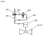
- the second and the third valve as shown in Fig. 3 are operated accordingly, i.e., when the solenoids S of the first and the second solenoid valve 201, 202 are in a resting position, a first flow path 203 is pressurized, which is not in fluid communication with the actuating means 206 for opening the second/third valve 20, 30.
- the second flow path 204 pressurizes said actuating means 206 with gas, which actuating means 206 then closes the second/third valve 20, 30.
- the respective second or third flow path 204, 205 pressurizes the actuating means 206 with said gas, which actuating means 206 then closes the second/third valve 20, 30.
- actuating means 206 then closes the second/third valve 20, 30.
- the method according to the invention particularly achieves the advantageous technical effect according to which the fluid medium (e.g. hydrocarbons) hold-up in the coil 40 can be lowered, thus reducing the risk of a "domino effect" extending the damages to the surrounding.
- nitrogen G is stored at an adequate pressure for injection into the system 1 before the pressure is lower than the nitrogen network.
Landscapes
- Engineering & Computer Science (AREA)
- Mechanical Engineering (AREA)
- General Engineering & Computer Science (AREA)
- Chemical & Material Sciences (AREA)
- Combustion & Propulsion (AREA)
- Production Of Liquid Hydrocarbon Mixture For Refining Petroleum (AREA)
- Feeding, Discharge, Calcimining, Fusing, And Gas-Generation Devices (AREA)
Description
- The invention relates to a method for inertization according to
claim 1. A system for inertization of a vessel is also discussed. - Heat is used in the process industry (from oil and gas to fine chemistry) to promote reactions, separation processes or to handle products. Heat can be transferred directly by burning a fuel in a fluid heater and transferring the energy from the combustion to the product contained in a coil or indirectly by heating a media (e.g. oil, water, or steam) and then transferring the energy to the product via a heat exchanger. Particularly, the present invention is concerned with fluid heaters. Fired heaters are defined on the API Std. 560 4th ed. as equipments where the "heat liberated by the combustion of fuels is transferred to fluids (other than water) contained in vessels, e.g. in the form of tubular coils, within an internally insulated enclosure". Excluding water, the fluid is normally flammable. Then, in case the coil breaks, hot hydrocarbons flow into the firing box of the furnace and start burning. The double action of heat released by the uncontrolled combustion on the leak and the internal pressure of the coil can diffuse the crack generating bigger fluid release that can drive also to an explosion.
- Methods and systems for purging coils while being treated inside a furnace are disclosed in
JP 07173523 JP 07027483 - Actually when such a coil develops a leak (e.g. a rupture) the actions to be taken are the following:
- 1. stop/reduce the fluid medium (e.g. hydrocarbon) inlet to the coil,
- 2. reduce combustion in the furnace,
- 3. reduce the pressure into the system down to the nitrogen network pressure and inject the nitrogen into the coil to displace the liquid out and extinguish the fire
- 4. stop the fuel to the furnace and shut down the furnace.
- The time lag between
steps - Thus, the problem underlying the present invention is to provide for a method and a system, which allow for reduction of said time lag or hold-up.
- This problem is solved by a method having the features of
claim 1. Preferred embodiments are stated in the respective sub claims and are described below. - According to
claim 1 the method according to the invention relates to inertization of a vessel, said vessel being a coil arranged in a furnace, said coil having an inlet and an outlet, wherein said inlet is connected to a first conduit and said outlet is connected to a second conduit, wherein a fluid medium is passed through the coil for heating said fluid medium therein, wherein particularly a fuel is combusted in said furnace for heating of said fluid medium flowing through said coil, the vessel having an inlet and an outlet, wherein said inlet is connected to a first conduit and said outlet is connected to a second conduit for passage of a fluid medium through said vessel via said conduits, the method further comprises the steps of: closing a first valve,e.g. a pneumatical failure close, failure open, or failure lock valve (wherein regarding a failure lock valve the valve does not move in case of air failure), of the first conduit upstream of said inlet for blocking passage of said fluid medium into the vessel, and injecting an inert medium, particularly an inert gas, particularly comprising nitrogen, into the first conduit downstream of said first valve as well as into the second conduit downstream of said outlet for inertization of said vessel, wherein said inert medium is injected into said first and second conduit at a pressure being equal to the pressure of said fluid medium in the vessel or at a pressure that differs from said pressure of the fluid medium in the vessel by less than 2 bar, particularly less than 1 bar, particularly less than 0.5 bar. In other words, the pressure of the inert medium (e.g. inert gas) essentially equals the pressure of the fluid medium, but may be a bit lower or higher.
Preferably, the inert medium (e.g. nitrogen or other inert gas) is injected into the broken vessel (e.g. coil) with a velocity ranging between 2 m/s and 20 m/s depending on the physical state of the heated medium (liquid or gas), on the operating conditions of the system and also on the system hold-up. The aim is to completely displace any liquid entrapped in the elbows without further damaging the vessel. - Preferably, the amount of inert medium (e.g. nitrogen or other inert gas) is enough to purge the vessel about four or five times, i.e., the amount of inert medium or inert gas injected into the vessel is preferably equal to four or five times the vessel volume at the actual conditions (injection pressure and ambient temperature).
- In case of a vessel failure (for instance a rupture with a fluid medium release, particularly hydrocarbons, into the firing box of the furnace), the invention thus advantageously reduces the hold-up of said medium. The inert medium (e.g. nitrogen) injection at said pressure does not need a prior reduction of the operating pressure so that displacement of the residual fluid medium (e.g. hydrocarbons) is possible right from the start leading to a quicker inertization of the environment. Hence, a particular advantage of the present invention is that the reduced hydrocarbons hold-up decreases the risk of a "domino effect" extending damages to the surrounding components. This is particularly achieved by storing said inert medium at an adequate pressure level that allows for injection into the system before the pressure is lower than that of the (e.g. nitrogen) network employed for inertization, particularly.
- According to an embodiment of the method according to the invention inert medium (e.g. inert gas) to be fed into said first conduit is stored in a first pressure tank prior to injection, preferably at said pressure level stated above. Particularly, the first pressure tank is connected to the first conduit via a second valve, which is opened for injecting said inert gas into the first conduit.
- Likewise, according to a further embodiment of the method according to the invention, inert medium (e.g. inert gas) to be injected into said second conduit is stored in a second pressure tank prior to injection, particularly at said pressure level stated above. Preferably, the second pressure tank is connected to the second conduit via a third valve, which is opened for injecting said inert gas into the second conduit.
- Further, in order to prevent back flow of said fluid medium into the coil, the second conduit comprises a check valve downstream of the point where said inert gas is injected into the second conduit.
- Preferably, the first, second, and/or third valve is designed as a pneumatical valve, i.e., a valve which is designed to be actuated pneumatically, e.g. by means of instrument air or nitrogen. While the first valve preferably is a failure close valve which opens upon actuation (the first valve may also be a failure open or failure lock valve), the second and/or third valve preferably is a failure open valve closing upon actuation. In a further embodiment, said check valve and the first valve may be interchanged. In yet another embodiment, said check valve may be substituted by an (e.g. pneumatical) fourth valve (e.g. a failure close, failure open or failure lock valve, see also above).
- Preferably, actuation pressure is provided for these valves by means of two three-way solenoid valves, which are preferably configured such that said (first, second, third and/or fourth) valve is opened/closed or activated (in case of a failure lock valve) when at least one of the solenoids can be electrically activated. Thus, reliability of the first, second and/or third valve is increased since either one of the two solenoids is allowed to fail.
- According to yet a further embodiment of the method according to the invention said second and third valves are opened at the same time.
- According to a further embodiment, the first and eventually the fourth valve, when actuated, are closed together before the second and the third valve are opened.
- According to another embodiment of the method according to the invention said fluid medium is combustible. Preferably, said fluid medium comprises one or several combustible hydrocarbons.
- According to the invention said vessel is a coil that is arranged in a furnace, particularly in a firing box of the latter, in which a fuel is combusted in the presence of an oxidant (e.g. air or oxygen), so that said fluid medium which is passed through the coil is heated.
- According to a further preferred embodiment of the method according to the invention the steps of closing said first valve and injecting said inert medium (e.g. inert gas) into the first and second conduit are conducted when a leak (e.g. a rupture) is detected in said coil. Said leak may for instance be detected by means of a carbon monoxide sensor, which may be for instance arranged in a stack of said furnace through which flue gas generated upon combustion is drawn off the furnace. Further, preferably, the fuel to the system is not completely stopped when a fire is detected, since in case the flammable fluid medium is not burned in the firing box an explosive atmosphere may be created. Preferably, the system is actuated manually, but can also be activated automatically based on the available information, e.g. CO content in the flue gas, furnace operating pressure or other suitable signals.
- According to a further embodiment of the method according to the invention, said inert medium (e.g. inert gas) is injected into the first and second conduit so as to push out said fluid medium out of the coil through said leak (e.g. rupture). Since inert medium is injected into the system on both sides of the coil as described above, said residual fluid medium can be pushed out of the ruptured coil more effectively.
- According thereto, to effectively render said vessel (e.g. coil) inert, a first pressure tank for storing an inert medium (e.g. inert gas) is provided, which first pressure tank is connected to said first conduit via a second valve, as well as a second pressure tank for storing an inert medium (e.g. inert gas), which second pressure tank is connected to said second conduit via a third valve, wherein the system is configured to inject said inert medium, particularly inert gas, particularly comprising nitrogen, out of the pressure tanks into the vessel via the first and second conduit for inertization of the vessel, particularly when a leak of said vessel is detected and/or the system is activated by an operator, particularly so as to push out said fluid medium out of vessel through said leak by means of the injected inert gas.
- According to the invention, said vessel is a tubular coil arranged in a furnace of said system, particularly in a firing box of said furnace, wherein the system is configured for passing said fluid medium through said coil for transferring heat to said fluid medium, wherein particularly the furnace is configured to combust a fuel in said furnace (particularly in said firing box) for heating of said fluid medium flowing through said coil.
- Further, in order to prevent back flow of said fluid medium into the vessel (e.g. coil), the second conduit preferably comprises a check or an automatic ON-OFF fourth valve (see above) downstream of the point where said inert gas flows into the second conduit. The position of the first valve and the check valve may also be interchanged (see above).
- According to a further embodiment according to the invention, the first, the second, the third and/or the fourth valve is preferably designed as a pneumatical valve, which is actuated pneumatically, e.g. by means of instrument air or nitrogen. While the first and eventually the fourth valve are preferably failure close valves which open upon actuation (the first and/or fourth valve may also be a failure open or a failure lock valve), the second and the third valve are preferably failure open valves closing upon actuation. As indicated above, actuation of the system is preferably conducted by an (e.g. plant) operator of the system once a leak of the vessel/coil is detected. The valves will be interlocked in order to open/close the valves in the right sequence.
- Preferably, actuation pressure is provided for these valves by means of two three-way solenoid valves, which are configured such that said first, second third and/or fourth valve is opened/closed or activated when at least one of the solenoids can be activated by means of electric power. Thus, reliability of the first, second and/or third valve is increased since either one of the two solenoids is allowed to fail, respectively.
- Further features and advantages of the invention shall be described by means of detailed descriptions of embodiments with reference to the Figures, wherein
- Fig. 1
- shows a schematical illustration of the method according to the invention and of the system which has been discussed;
- Fig. 2
- shows a failure close valve used as first valve of the system shown in
Fig. 1 ; - Fig. 3
- shows a failure open valve used as second and third valve of the system shown in
Fig. 1 ; - Fig. 4
- shows a modification of the system and method illustrated in
Fig. 1 , wherein the first and the check valve are interchanged; - Fig. 5
- shows a modification of the system and method illustrated in
Fig. 1 , wherein the check valve is interchanged by an (e.g. pneumatical) fourth valve being preferably either a failure close, failure open or failure lock valve. -
Fig. 1 shows in conjunction withFigs. 2 and3 asystem 1 for rendering a vessel in the form of atubular coil 40 inert that is arranged in a firing box of afurnace 2, in which a fuel F is combusted in the presence of an oxidant O like air for instance. The heat produced upon combustion of said fuel F is transferred to a combustible fluid medium M comprising combustible hydrocarbons flowing through saidtubular coil 40 for heating of said fluid medium M. - Said
coil 40 comprises aninlet 41 connected to afirst conduit 22 as well as anoutlet 42 connected to asecond conduit 32 so that fluid medium M can be fed into thecoil 40 via thefirst conduit 22 and drawn of thecoil 40 via thesecond conduit 32. In order to stop or reduce passage of fluid medium M into thecoil 40, thefirst conduit 22 preferably comprises afirst valve 10 for reducing or stopping flow of fluid medium M into thecoil 40. Further, for preventing back flow of fluid medium M into thecoil 40, acheck valve 50 is provided in thesecond conduit 32. - Now, in case of a rupture R of the coil, a part of the fluid medium M is discharged into the
furnace 2 which may lead to an uncontrolled burning of the fluid medium M causing damage to thefurnace 2 and eventually surrounding components. - In order to quickly render the
coil 40 and components connected thereto inert, thesystem 1 thus comprises afirst pressure tank 21 being connected via asecond valve 20 to thefirst conduit 22 downstream of thefirst valve 10 as well as asecond pressure tank 31 being connected to thesecond conduit 32 upstream of saidcheck valve 50. Thepressure tanks second conduit coil 40. This allows for pushing out the fluid medium M through the rupture R of thecoil 40 and for inertization of thecoil 40 as well as components being in fluid connection with thecoil 40 like the first andsecond conduit coil 40 and to push out the residual fluid medium M through the rupture R. - For detecting such a rupture R in the
coil 40, thefurnace 2 may comprise aCO sensor 4 provided in astack 3 of thefurnace 2 via which stack 3 flue gas generated in thefurnace 2 due to combustion of said fuel F is drawn off thefurnace 2. Preferably, saidsensor 4 is designed to detect an increase in CO generation due to combustion of fluid medium M that is discharged through rupture R into thefurnace 2. - Once a rupture R is detected in the
coil 40, an operator may trigger injection of nitrogen G into thecoil 40 manually. Thesystem 1 will then automatically close thefirst valve 10 for blocking passage of fluid medium M into thecoil 40, reduce flow of fuel F and/or oxidant O into thefurnace 2 and open the second andthird valve second conduit coil 40 and pushes out residual fluid medium M through said rupture R thus rendering thecoil 40 inert. - As shown in
Fig, 4 , thefirst valve 10 and thecheck valve 50 may also be interchanged. Further as shown inFig. 5 , instead of acheck valve 50, also a fourth (e.g. pneumatical) valve 10' may be used. The first 10 and the fourth valve 10' can be (e.g. pneumatical) failure close, failure open or failure lock valves. The second and thethird valves - In the embodiment shown in
Fig. 2 , thefirst valve 10 is a pneumatically actuated failure close valve, which is actuated by means of a first and a second solenoid three-way valve valves second solenoid valve first valve 10. In case both solenoids S are electrically actuated, asecond flow path 104 is pressurized with said gas which pressurizes said actuating means 106 which then closes the first valve. In case only one of the solenoids S can be electrically actuated, the respective second orthird flow path first valve 10. Thus, merely one functioning solenoid S is needed to operate thefirst valve 10 successfully. - The second and the third valve as shown in
Fig. 3 are operated accordingly, i.e., when the solenoids S of the first and thesecond solenoid valve first flow path 203 is pressurized, which is not in fluid communication with the actuating means 206 for opening the second/third valve second flow path 204 pressurizes said actuating means 206 with gas, which actuating means 206 then closes the second/third valve third flow path third valve third valve - As a result, the method according to the invention particularly achieves the advantageous technical effect according to which the fluid medium (e.g. hydrocarbons) hold-up in the
coil 40 can be lowered, thus reducing the risk of a "domino effect" extending the damages to the surrounding. In this regard, nitrogen G is stored at an adequate pressure for injection into thesystem 1 before the pressure is lower than the nitrogen network.Reference Numerals 1 System for inertization 2 Furnace 3 Stack 4 Sensor 10 First valve (e.g. failure close, open or lock) 20 Second valve (e.g. failure open) 10' fourth valve (e.g. failure close, open or lock) 21 First pressure tank 22 First conduit 30 Third valve (e.g. failure open) 31 Pressure tank 32 Second conduit 40 Vessel (e.g. coil) 41 Inlet of vessel 42 Outlet of vessel 50 Check valve 101, 201 First solenoid valve 102, 202 Second solenoid valve 103, 203 First flow path 104, 204 Second flow path 105, 205 Third flow path 106, 206 Actuating means F Fuel M Fluid medium (e.g. combustible) O Oxidant R Leak S Solenoid
Claims (13)
- Method for inertization of a vessel, said vessel is a coil arranged in a furnace (2), said vessel (40) having an inlet (41) and an outlet (42), wherein said inlet (41) is connected to a first conduit (22) and said outlet (42) is connected to a second conduit (32), wherein a fluid medium (M) is passed through the coil (40) for heating said fluid medium (40) therein, comprising the steps of:- closing a first valve (10) of the first conduit (22) upstream of said inlet (41) for blocking passage of said fluid (M) medium into the vessel (40),- injecting an inert medium (G) into the first conduit (22) downstream of said first valve (10) as well as into the second conduit (32) downstream of said outlet (42) for inertization of said vessel (40), and- wherein said inert medium (G) is injected into said first and second conduit (22, 32) at a pressure being equal to the pressure of said fluid medium (M) in the vessel (40) or at a pressure that differs from said pressure of the fluid medium (M) in the vessel (40) by less than 2 bar.
- Method according to claim 1, characterized in that inert medium (G) to be injected into said first conduit (22) is stored in a first pressure tank (21) prior to injection, wherein the first pressure tank (21) is connected to the first conduit (22) via a second valve (20), particularly in the form of a pneumatical valve, wherein the second valve (20) is opened for injecting said inert medium (G) into the first conduit (22).
- Method according to one of the preceding claims, characterized in that inert medium (G) to be injected into said second conduit (32) is stored in a second pressure tank (31) prior to injection, wherein the second pressure tank (32) is connected to the second conduit (32) via a third valve (30), particularly in the form of a pneumatical valve, wherein the third valve (30) is opened for injecting said inert medium (G) into the second conduit (32).
- Method according to claims 2 and 3, characterized in that said second and third valves (20, 30) are opened at the same time.
- Method according to one of the claims 2 to 4, characterized in that the first valve (10) is closed before opening of the second valve (20) and/or third valve (30), wherein particularly also a fourth valve (10') of the second conduit (32), which fourth valve (10) is arranged downstream of said outlet (42) and downstream of the point where inert medium (G) is injected into the second conduit (32), is closed before opening of the second valve (20) and/or third valve (30).
- Method according to one of the preceding claims, characterized in that said fluid medium (M) is combustible.
- Method according to one of the preceding claims, characterized in that said fluid medium (M) comprises a hydrocarbon.
- Method according to one of the preceding claims, characterized in that the steps of closing said first valve (10), and particularly said fourth valve (10'), and injecting said inert medium (G) are conducted when a leak (R) is detected in said vessel (40).
- Method according to claim 8, characterized in that said inert medium (G) is injected into the first and second conduit (22, 32) so as to push said fluid medium (M) out of the coil (40) through said leak (R).
- Method according to one of the preceding claims, characterized in that a fuel (F) is combusted in said furnace (2) for heating of said fluid medium (M) flowing through said coil (40).
- Method according to one of the preceding claims, characterized in that, said inert medium (G) is an inert gas, particularly nitrogen.
- Method according to one of the preceding claims, characterized in that, said inert medium (G) is injected into said first and second conduit (22, 32) at a pressure that differs from said pressure of the fluid medium (M) in the vessel (40) by less than 1 bar.
- Method according to one of the preceding claims, characterized in that, said inert medium (G) is injected into said first and second conduit (22, 32) at a pressure that differs from said pressure of the fluid medium (M) in the vessel (40) by less than 0.5 bar.
Priority Applications (6)
| Application Number | Priority Date | Filing Date | Title |
|---|---|---|---|
| PL13004441T PL2848884T3 (en) | 2013-09-12 | 2013-09-12 | Method for inertization of a vessel, particularly in the form of a coil arranged in a furnace |
| ES13004441.5T ES2599810T3 (en) | 2013-09-12 | 2013-09-12 | Method for making a container inert, in particular in the form of a coil arranged in an oven |
| EP13004441.5A EP2848884B1 (en) | 2013-09-12 | 2013-09-12 | Method for inertization of a vessel, particularly in the form of a coil arranged in a furnace |
| PT130044415T PT2848884T (en) | 2013-09-12 | 2013-09-12 | Method for inertization of a vessel, particularly in the form of a coil arranged in a furnace |
| DK13004441.5T DK2848884T3 (en) | 2013-09-12 | 2013-09-12 | Method for inertizing a container, in particular in the form of a coil disposed in an oven |
| HUE13004441A HUE030864T2 (en) | 2013-09-12 | 2013-09-12 | Method for inertization of a vessel, particularly in the form of a coil arranged in a furnace |
Applications Claiming Priority (1)
| Application Number | Priority Date | Filing Date | Title |
|---|---|---|---|
| EP13004441.5A EP2848884B1 (en) | 2013-09-12 | 2013-09-12 | Method for inertization of a vessel, particularly in the form of a coil arranged in a furnace |
Publications (2)
| Publication Number | Publication Date |
|---|---|
| EP2848884A1 EP2848884A1 (en) | 2015-03-18 |
| EP2848884B1 true EP2848884B1 (en) | 2016-08-03 |
Family
ID=49236980
Family Applications (1)
| Application Number | Title | Priority Date | Filing Date |
|---|---|---|---|
| EP13004441.5A Not-in-force EP2848884B1 (en) | 2013-09-12 | 2013-09-12 | Method for inertization of a vessel, particularly in the form of a coil arranged in a furnace |
Country Status (6)
| Country | Link |
|---|---|
| EP (1) | EP2848884B1 (en) |
| DK (1) | DK2848884T3 (en) |
| ES (1) | ES2599810T3 (en) |
| HU (1) | HUE030864T2 (en) |
| PL (1) | PL2848884T3 (en) |
| PT (1) | PT2848884T (en) |
Families Citing this family (1)
| Publication number | Priority date | Publication date | Assignee | Title |
|---|---|---|---|---|
| EP3912688A1 (en) * | 2020-05-19 | 2021-11-24 | L'air Liquide, Société Anonyme Pour L'Étude Et L'exploitation Des Procédés Georges Claude | Secure inerting device |
Citations (2)
| Publication number | Priority date | Publication date | Assignee | Title |
|---|---|---|---|---|
| JPH0727483A (en) * | 1993-07-16 | 1995-01-27 | Chugai Ro Co Ltd | Roller hearth type heat treatment furnace for pipe coil |
| JPH07173523A (en) * | 1993-12-16 | 1995-07-11 | Furukawa Electric Co Ltd:The | Tray for heat treatment of pipe coil |
Family Cites Families (5)
| Publication number | Priority date | Publication date | Assignee | Title |
|---|---|---|---|---|
| RO77766A2 (en) * | 1979-10-12 | 1981-12-25 | Institutul De Cercetari Si Proiectari Pentru Petrol Si Gaze,Ro | METHOD AND DEVICE FOR SUPPLYING OR INTERRUPTING FUEL FEEDING OF AN OIL HEATER |
| US7536274B2 (en) * | 2004-05-28 | 2009-05-19 | Fisher-Rosemount Systems, Inc. | System and method for detecting an abnormal situation associated with a heater |
| US9157682B2 (en) * | 2011-02-10 | 2015-10-13 | Linde Aktiengesellschaft | Furnace atmosphere generator |
| FR2973862B1 (en) * | 2011-04-06 | 2013-03-29 | F M I Process Sa | CREMATION OVEN COMPRISING A COMBUSTION CONTROL DEVICE AND CREMATION SYSTEM COMPRISING SUCH A FURNACE |
| AU2012278907B2 (en) * | 2011-07-01 | 2014-09-11 | Anaeco Limited | Inerting method in digestion |
-
2013
- 2013-09-12 ES ES13004441.5T patent/ES2599810T3/en active Active
- 2013-09-12 PL PL13004441T patent/PL2848884T3/en unknown
- 2013-09-12 PT PT130044415T patent/PT2848884T/en unknown
- 2013-09-12 HU HUE13004441A patent/HUE030864T2/en unknown
- 2013-09-12 DK DK13004441.5T patent/DK2848884T3/en active
- 2013-09-12 EP EP13004441.5A patent/EP2848884B1/en not_active Not-in-force
Patent Citations (2)
| Publication number | Priority date | Publication date | Assignee | Title |
|---|---|---|---|---|
| JPH0727483A (en) * | 1993-07-16 | 1995-01-27 | Chugai Ro Co Ltd | Roller hearth type heat treatment furnace for pipe coil |
| JPH07173523A (en) * | 1993-12-16 | 1995-07-11 | Furukawa Electric Co Ltd:The | Tray for heat treatment of pipe coil |
Also Published As
| Publication number | Publication date |
|---|---|
| ES2599810T3 (en) | 2017-02-03 |
| PT2848884T (en) | 2016-09-13 |
| PL2848884T3 (en) | 2017-08-31 |
| DK2848884T3 (en) | 2016-11-28 |
| EP2848884A1 (en) | 2015-03-18 |
| HUE030864T2 (en) | 2017-06-28 |
Similar Documents
| Publication | Publication Date | Title |
|---|---|---|
| JP2007132349A (en) | Method and apparatus for combustion turbine nitrogen purge system | |
| US10544902B2 (en) | Liquefied natural gas vaporizer for downhole oil or gas applications | |
| CN111396746B (en) | Process and device for thermal venting of valve chamber of liquid-phase ethane pipeline | |
| FR2881209A1 (en) | GAS INCINERATOR INSTALLED ON A LIQUEFIED GAS TRANSPORT VESSEL | |
| JP6310707B2 (en) | Operation method of fuel heating system | |
| CN216273965U (en) | Multi-nozzle pulverized coal gasification device | |
| KR20160016130A (en) | Inert gas supplying ship | |
| EP2848884A1 (en) | Method and System for inertization of a vessel, particularly in the form of a coil arranged in a furnace | |
| Chang et al. | Revisiting of a silane explosion in a photovoltaic fabrication plant | |
| JP2014109399A (en) | Method for detecting leakage of valve and combustion facility | |
| JP5502318B2 (en) | Device for preventing the propagation of the flame front | |
| JP2009203944A (en) | Method and device for supplying gas fuel of binary fuel engine | |
| CN104791843B (en) | Cold-state prefiring gas replacement operation method of full gas fired boiler | |
| US3405690A (en) | Method of and means for operating fired processing equipment | |
| EP2451712B1 (en) | System and method for testing propellant devices | |
| CN102828833B (en) | For running the method for the fuel supply system of heat engine | |
| CN110686233A (en) | CFB boiler primary hot air duct pressure fire explosion-proof device and explosion-proof method | |
| CN214377046U (en) | A miniaturized controllable ignition device for simulating fire training | |
| US3232332A (en) | Fuel burner control arrangement | |
| KR101973039B1 (en) | Inert gas transportation apparatus of liquid cargo for vessel and the operating method of it | |
| CN113853516A (en) | Apparatus, system, and method for maintaining fluid-carrying structures | |
| Booman et al. | Failures in cabin type hydrocarbon heaters due to inadequate fuel control | |
| JP2005308185A (en) | High-pressure gas introducing method | |
| US5426259A (en) | Method for oil-extracting treatment of wastes | |
| RU2791800C1 (en) | Intratubal device start-up control system |
Legal Events
| Date | Code | Title | Description |
|---|---|---|---|
| PUAI | Public reference made under article 153(3) epc to a published international application that has entered the european phase |
Free format text: ORIGINAL CODE: 0009012 |
|
| 17P | Request for examination filed |
Effective date: 20130912 |
|
| AK | Designated contracting states |
Kind code of ref document: A1 Designated state(s): AL AT BE BG CH CY CZ DE DK EE ES FI FR GB GR HR HU IE IS IT LI LT LU LV MC MK MT NL NO PL PT RO RS SE SI SK SM TR |
|
| AX | Request for extension of the european patent |
Extension state: BA ME |
|
| R17P | Request for examination filed (corrected) |
Effective date: 20150402 |
|
| RBV | Designated contracting states (corrected) |
Designated state(s): AL AT BE BG CH CY CZ DE DK EE ES FI FR GB GR HR HU IE IS IT LI LT LU LV MC MK MT NL NO PL PT RO RS SE SI SK SM TR |
|
| 17Q | First examination report despatched |
Effective date: 20150911 |
|
| GRAJ | Information related to disapproval of communication of intention to grant by the applicant or resumption of examination proceedings by the epo deleted |
Free format text: ORIGINAL CODE: EPIDOSDIGR1 |
|
| GRAP | Despatch of communication of intention to grant a patent |
Free format text: ORIGINAL CODE: EPIDOSNIGR1 |
|
| INTG | Intention to grant announced |
Effective date: 20160503 |
|
| RIN1 | Information on inventor provided before grant (corrected) |
Inventor name: GUSBERTI, AMBROGIO |
|
| GRAS | Grant fee paid |
Free format text: ORIGINAL CODE: EPIDOSNIGR3 |
|
| GRAA | (expected) grant |
Free format text: ORIGINAL CODE: 0009210 |
|
| AK | Designated contracting states |
Kind code of ref document: B1 Designated state(s): AL AT BE BG CH CY CZ DE DK EE ES FI FR GB GR HR HU IE IS IT LI LT LU LV MC MK MT NL NO PL PT RO RS SE SI SK SM TR |
|
| REG | Reference to a national code |
Ref country code: GB Ref legal event code: FG4D |
|
| REG | Reference to a national code |
Ref country code: CH Ref legal event code: EP Ref country code: AT Ref legal event code: REF Ref document number: 817608 Country of ref document: AT Kind code of ref document: T Effective date: 20160815 |
|
| REG | Reference to a national code |
Ref country code: FR Ref legal event code: PLFP Year of fee payment: 4 |
|
| REG | Reference to a national code |
Ref country code: IE Ref legal event code: FG4D |
|
| REG | Reference to a national code |
Ref country code: PT Ref legal event code: SC4A Ref document number: 2848884 Country of ref document: PT Date of ref document: 20160913 Kind code of ref document: T Free format text: AVAILABILITY OF NATIONAL TRANSLATION Effective date: 20160907 |
|
| REG | Reference to a national code |
Ref country code: DE Ref legal event code: R096 Ref document number: 602013009985 Country of ref document: DE |
|
| REG | Reference to a national code |
Ref country code: RO Ref legal event code: EPE |
|
| REG | Reference to a national code |
Ref country code: NL Ref legal event code: FP |
|
| REG | Reference to a national code |
Ref country code: SE Ref legal event code: TRGR |
|
| REG | Reference to a national code |
Ref country code: DK Ref legal event code: T3 Effective date: 20161121 |
|
| REG | Reference to a national code |
Ref country code: LT Ref legal event code: MG4D Ref country code: NO Ref legal event code: T2 Effective date: 20160803 |
|
| PG25 | Lapsed in a contracting state [announced via postgrant information from national office to epo] |
Ref country code: HR Free format text: LAPSE BECAUSE OF FAILURE TO SUBMIT A TRANSLATION OF THE DESCRIPTION OR TO PAY THE FEE WITHIN THE PRESCRIBED TIME-LIMIT Effective date: 20160803 Ref country code: IS Free format text: LAPSE BECAUSE OF FAILURE TO SUBMIT A TRANSLATION OF THE DESCRIPTION OR TO PAY THE FEE WITHIN THE PRESCRIBED TIME-LIMIT Effective date: 20161203 Ref country code: RS Free format text: LAPSE BECAUSE OF FAILURE TO SUBMIT A TRANSLATION OF THE DESCRIPTION OR TO PAY THE FEE WITHIN THE PRESCRIBED TIME-LIMIT Effective date: 20160803 Ref country code: LT Free format text: LAPSE BECAUSE OF FAILURE TO SUBMIT A TRANSLATION OF THE DESCRIPTION OR TO PAY THE FEE WITHIN THE PRESCRIBED TIME-LIMIT Effective date: 20160803 |
|
| REG | Reference to a national code |
Ref country code: SK Ref legal event code: T3 Ref document number: E 22365 Country of ref document: SK |
|
| REG | Reference to a national code |
Ref country code: ES Ref legal event code: FG2A Ref document number: 2599810 Country of ref document: ES Kind code of ref document: T3 Effective date: 20170203 |
|
| PG25 | Lapsed in a contracting state [announced via postgrant information from national office to epo] |
Ref country code: LV Free format text: LAPSE BECAUSE OF FAILURE TO SUBMIT A TRANSLATION OF THE DESCRIPTION OR TO PAY THE FEE WITHIN THE PRESCRIBED TIME-LIMIT Effective date: 20160803 |
|
| REG | Reference to a national code |
Ref country code: GR Ref legal event code: EP Ref document number: 20160402713 Country of ref document: GR Effective date: 20170130 |
|
| REG | Reference to a national code |
Ref country code: AT Ref legal event code: UEP Ref document number: 817608 Country of ref document: AT Kind code of ref document: T Effective date: 20160803 |
|
| PG25 | Lapsed in a contracting state [announced via postgrant information from national office to epo] |
Ref country code: EE Free format text: LAPSE BECAUSE OF FAILURE TO SUBMIT A TRANSLATION OF THE DESCRIPTION OR TO PAY THE FEE WITHIN THE PRESCRIBED TIME-LIMIT Effective date: 20160803 |
|
| REG | Reference to a national code |
Ref country code: DE Ref legal event code: R097 Ref document number: 602013009985 Country of ref document: DE |
|
| PG25 | Lapsed in a contracting state [announced via postgrant information from national office to epo] |
Ref country code: SM Free format text: LAPSE BECAUSE OF FAILURE TO SUBMIT A TRANSLATION OF THE DESCRIPTION OR TO PAY THE FEE WITHIN THE PRESCRIBED TIME-LIMIT Effective date: 20160803 Ref country code: BG Free format text: LAPSE BECAUSE OF FAILURE TO SUBMIT A TRANSLATION OF THE DESCRIPTION OR TO PAY THE FEE WITHIN THE PRESCRIBED TIME-LIMIT Effective date: 20161103 |
|
| PLBE | No opposition filed within time limit |
Free format text: ORIGINAL CODE: 0009261 |
|
| STAA | Information on the status of an ep patent application or granted ep patent |
Free format text: STATUS: NO OPPOSITION FILED WITHIN TIME LIMIT |
|
| REG | Reference to a national code |
Ref country code: HU Ref legal event code: AG4A Ref document number: E030864 Country of ref document: HU Ref country code: IE Ref legal event code: MM4A |
|
| PG25 | Lapsed in a contracting state [announced via postgrant information from national office to epo] |
Ref country code: MC Free format text: LAPSE BECAUSE OF FAILURE TO SUBMIT A TRANSLATION OF THE DESCRIPTION OR TO PAY THE FEE WITHIN THE PRESCRIBED TIME-LIMIT Effective date: 20160803 |
|
| 26N | No opposition filed |
Effective date: 20170504 |
|
| PG25 | Lapsed in a contracting state [announced via postgrant information from national office to epo] |
Ref country code: IE Free format text: LAPSE BECAUSE OF NON-PAYMENT OF DUE FEES Effective date: 20160912 |
|
| REG | Reference to a national code |
Ref country code: FR Ref legal event code: PLFP Year of fee payment: 5 |
|
| PG25 | Lapsed in a contracting state [announced via postgrant information from national office to epo] |
Ref country code: LU Free format text: LAPSE BECAUSE OF NON-PAYMENT OF DUE FEES Effective date: 20160912 Ref country code: SI Free format text: LAPSE BECAUSE OF FAILURE TO SUBMIT A TRANSLATION OF THE DESCRIPTION OR TO PAY THE FEE WITHIN THE PRESCRIBED TIME-LIMIT Effective date: 20160803 |
|
| PGFP | Annual fee paid to national office [announced via postgrant information from national office to epo] |
Ref country code: CZ Payment date: 20170811 Year of fee payment: 5 Ref country code: SK Payment date: 20170728 Year of fee payment: 5 Ref country code: NO Payment date: 20170911 Year of fee payment: 5 Ref country code: GR Payment date: 20170810 Year of fee payment: 5 Ref country code: RO Payment date: 20170726 Year of fee payment: 5 Ref country code: GB Payment date: 20170906 Year of fee payment: 5 Ref country code: IT Payment date: 20170925 Year of fee payment: 5 Ref country code: FR Payment date: 20170810 Year of fee payment: 5 Ref country code: DE Payment date: 20170905 Year of fee payment: 5 Ref country code: CH Payment date: 20170912 Year of fee payment: 5 Ref country code: FI Payment date: 20170911 Year of fee payment: 5 |
|
| PGFP | Annual fee paid to national office [announced via postgrant information from national office to epo] |
Ref country code: NL Payment date: 20170915 Year of fee payment: 5 Ref country code: BE Payment date: 20170724 Year of fee payment: 5 Ref country code: TR Payment date: 20170906 Year of fee payment: 5 Ref country code: PL Payment date: 20170710 Year of fee payment: 5 Ref country code: DK Payment date: 20170912 Year of fee payment: 5 Ref country code: PT Payment date: 20170904 Year of fee payment: 5 Ref country code: SE Payment date: 20170912 Year of fee payment: 5 Ref country code: HU Payment date: 20170809 Year of fee payment: 5 |
|
| PGFP | Annual fee paid to national office [announced via postgrant information from national office to epo] |
Ref country code: ES Payment date: 20171002 Year of fee payment: 5 |
|
| PG25 | Lapsed in a contracting state [announced via postgrant information from national office to epo] |
Ref country code: MT Free format text: LAPSE BECAUSE OF NON-PAYMENT OF DUE FEES Effective date: 20160930 Ref country code: CY Free format text: LAPSE BECAUSE OF FAILURE TO SUBMIT A TRANSLATION OF THE DESCRIPTION OR TO PAY THE FEE WITHIN THE PRESCRIBED TIME-LIMIT Effective date: 20160803 Ref country code: MK Free format text: LAPSE BECAUSE OF FAILURE TO SUBMIT A TRANSLATION OF THE DESCRIPTION OR TO PAY THE FEE WITHIN THE PRESCRIBED TIME-LIMIT Effective date: 20160803 |
|
| PG25 | Lapsed in a contracting state [announced via postgrant information from national office to epo] |
Ref country code: AL Free format text: LAPSE BECAUSE OF FAILURE TO SUBMIT A TRANSLATION OF THE DESCRIPTION OR TO PAY THE FEE WITHIN THE PRESCRIBED TIME-LIMIT Effective date: 20160803 |
|
| REG | Reference to a national code |
Ref country code: DE Ref legal event code: R119 Ref document number: 602013009985 Country of ref document: DE |
|
| REG | Reference to a national code |
Ref country code: NO Ref legal event code: MMEP |
|
| PG25 | Lapsed in a contracting state [announced via postgrant information from national office to epo] |
Ref country code: CZ Free format text: LAPSE BECAUSE OF NON-PAYMENT OF DUE FEES Effective date: 20180912 Ref country code: FI Free format text: LAPSE BECAUSE OF NON-PAYMENT OF DUE FEES Effective date: 20180912 Ref country code: RO Free format text: LAPSE BECAUSE OF NON-PAYMENT OF DUE FEES Effective date: 20180912 |
|
| REG | Reference to a national code |
Ref country code: SE Ref legal event code: EUG Ref country code: CH Ref legal event code: PL |
|
| REG | Reference to a national code |
Ref country code: DK Ref legal event code: EBP Effective date: 20180930 |
|
| REG | Reference to a national code |
Ref country code: NL Ref legal event code: MM Effective date: 20181001 |
|
| GBPC | Gb: european patent ceased through non-payment of renewal fee |
Effective date: 20180912 |
|
| PG25 | Lapsed in a contracting state [announced via postgrant information from national office to epo] |
Ref country code: SE Free format text: LAPSE BECAUSE OF NON-PAYMENT OF DUE FEES Effective date: 20180913 Ref country code: PT Free format text: LAPSE BECAUSE OF NON-PAYMENT OF DUE FEES Effective date: 20190312 |
|
| REG | Reference to a national code |
Ref country code: SK Ref legal event code: MM4A Ref document number: E 22365 Country of ref document: SK Effective date: 20180912 |
|
| REG | Reference to a national code |
Ref country code: BE Ref legal event code: FP Effective date: 20161021 Ref country code: BE Ref legal event code: MM Effective date: 20180930 |
|
| PG25 | Lapsed in a contracting state [announced via postgrant information from national office to epo] |
Ref country code: NL Free format text: LAPSE BECAUSE OF NON-PAYMENT OF DUE FEES Effective date: 20181001 |
|
| PG25 | Lapsed in a contracting state [announced via postgrant information from national office to epo] |
Ref country code: DE Free format text: LAPSE BECAUSE OF NON-PAYMENT OF DUE FEES Effective date: 20190402 Ref country code: NO Free format text: LAPSE BECAUSE OF NON-PAYMENT OF DUE FEES Effective date: 20180930 Ref country code: IT Free format text: LAPSE BECAUSE OF NON-PAYMENT OF DUE FEES Effective date: 20180912 |
|
| PG25 | Lapsed in a contracting state [announced via postgrant information from national office to epo] |
Ref country code: SK Free format text: LAPSE BECAUSE OF NON-PAYMENT OF DUE FEES Effective date: 20180912 Ref country code: LI Free format text: LAPSE BECAUSE OF NON-PAYMENT OF DUE FEES Effective date: 20180930 Ref country code: FR Free format text: LAPSE BECAUSE OF NON-PAYMENT OF DUE FEES Effective date: 20180930 Ref country code: BE Free format text: LAPSE BECAUSE OF NON-PAYMENT OF DUE FEES Effective date: 20180930 Ref country code: CH Free format text: LAPSE BECAUSE OF NON-PAYMENT OF DUE FEES Effective date: 20180930 Ref country code: HU Free format text: LAPSE BECAUSE OF NON-PAYMENT OF DUE FEES Effective date: 20180913 Ref country code: GR Free format text: LAPSE BECAUSE OF NON-PAYMENT OF DUE FEES Effective date: 20190402 |
|
| REG | Reference to a national code |
Ref country code: ES Ref legal event code: FD2A Effective date: 20191030 |
|
| PG25 | Lapsed in a contracting state [announced via postgrant information from national office to epo] |
Ref country code: GB Free format text: LAPSE BECAUSE OF NON-PAYMENT OF DUE FEES Effective date: 20180912 Ref country code: DK Free format text: LAPSE BECAUSE OF NON-PAYMENT OF DUE FEES Effective date: 20180930 |
|
| REG | Reference to a national code |
Ref country code: AT Ref legal event code: MM01 Ref document number: 817608 Country of ref document: AT Kind code of ref document: T Effective date: 20180912 |
|
| PG25 | Lapsed in a contracting state [announced via postgrant information from national office to epo] |
Ref country code: AT Free format text: LAPSE BECAUSE OF NON-PAYMENT OF DUE FEES Effective date: 20180912 |
|
| PG25 | Lapsed in a contracting state [announced via postgrant information from national office to epo] |
Ref country code: ES Free format text: LAPSE BECAUSE OF NON-PAYMENT OF DUE FEES Effective date: 20180913 Ref country code: PL Free format text: LAPSE BECAUSE OF NON-PAYMENT OF DUE FEES Effective date: 20180912 |
|
| PG25 | Lapsed in a contracting state [announced via postgrant information from national office to epo] |
Ref country code: TR Free format text: LAPSE BECAUSE OF NON-PAYMENT OF DUE FEES Effective date: 20180912 |