EP2848834B1 - Tubular body for mounting on a shaft or a bore and method for mounting same - Google Patents
Tubular body for mounting on a shaft or a bore and method for mounting same Download PDFInfo
- Publication number
- EP2848834B1 EP2848834B1 EP14177530.4A EP14177530A EP2848834B1 EP 2848834 B1 EP2848834 B1 EP 2848834B1 EP 14177530 A EP14177530 A EP 14177530A EP 2848834 B1 EP2848834 B1 EP 2848834B1
- Authority
- EP
- European Patent Office
- Prior art keywords
- layer
- tubular body
- radially
- radially inner
- inner layer
- Prior art date
- Legal status (The legal status is an assumption and is not a legal conclusion. Google has not performed a legal analysis and makes no representation as to the accuracy of the status listed.)
- Active
Links
- 238000000034 method Methods 0.000 title claims description 23
- 239000000463 material Substances 0.000 claims description 49
- 239000011151 fibre-reinforced plastic Substances 0.000 claims description 25
- 229920002430 Fibre-reinforced plastic Polymers 0.000 claims description 24
- 239000007769 metal material Substances 0.000 claims description 14
- 239000000835 fiber Substances 0.000 claims description 12
- 239000002131 composite material Substances 0.000 claims description 9
- 238000001816 cooling Methods 0.000 claims description 7
- 238000010438 heat treatment Methods 0.000 claims description 5
- 239000000919 ceramic Substances 0.000 claims description 2
- 229920003023 plastic Polymers 0.000 claims description 2
- 239000004033 plastic Substances 0.000 claims description 2
- 230000000694 effects Effects 0.000 claims 2
- 230000008602 contraction Effects 0.000 description 7
- 229910000831 Steel Inorganic materials 0.000 description 5
- 238000005096 rolling process Methods 0.000 description 5
- 239000010959 steel Substances 0.000 description 5
- XEEYBQQBJWHFJM-UHFFFAOYSA-N Iron Chemical compound [Fe] XEEYBQQBJWHFJM-UHFFFAOYSA-N 0.000 description 4
- 229910052751 metal Inorganic materials 0.000 description 4
- 239000002184 metal Substances 0.000 description 4
- 239000004918 carbon fiber reinforced polymer Substances 0.000 description 3
- VYZAMTAEIAYCRO-UHFFFAOYSA-N Chromium Chemical compound [Cr] VYZAMTAEIAYCRO-UHFFFAOYSA-N 0.000 description 2
- RYGMFSIKBFXOCR-UHFFFAOYSA-N Copper Chemical compound [Cu] RYGMFSIKBFXOCR-UHFFFAOYSA-N 0.000 description 2
- 239000000956 alloy Substances 0.000 description 2
- 229910045601 alloy Inorganic materials 0.000 description 2
- 229910052782 aluminium Inorganic materials 0.000 description 2
- XAGFODPZIPBFFR-UHFFFAOYSA-N aluminium Chemical compound [Al] XAGFODPZIPBFFR-UHFFFAOYSA-N 0.000 description 2
- 229920006231 aramid fiber Polymers 0.000 description 2
- 229910010293 ceramic material Inorganic materials 0.000 description 2
- 229910052804 chromium Inorganic materials 0.000 description 2
- 239000011651 chromium Substances 0.000 description 2
- 229910052802 copper Inorganic materials 0.000 description 2
- 239000010949 copper Substances 0.000 description 2
- 239000011152 fibreglass Substances 0.000 description 2
- 229910052742 iron Inorganic materials 0.000 description 2
- 239000011159 matrix material Substances 0.000 description 2
- 239000007787 solid Substances 0.000 description 2
- OKTJSMMVPCPJKN-UHFFFAOYSA-N Carbon Chemical compound [C] OKTJSMMVPCPJKN-UHFFFAOYSA-N 0.000 description 1
- 239000004760 aramid Substances 0.000 description 1
- 229910052799 carbon Inorganic materials 0.000 description 1
- 239000004917 carbon fiber Substances 0.000 description 1
- 238000005553 drilling Methods 0.000 description 1
- 239000005447 environmental material Substances 0.000 description 1
- 239000003365 glass fiber Substances 0.000 description 1
- 238000004519 manufacturing process Methods 0.000 description 1
- 239000012783 reinforcing fiber Substances 0.000 description 1
- 239000011347 resin Substances 0.000 description 1
- 229920005989 resin Polymers 0.000 description 1
- 229920001169 thermoplastic Polymers 0.000 description 1
- 229920001187 thermosetting polymer Polymers 0.000 description 1
- 239000004416 thermosoftening plastic Substances 0.000 description 1
- 238000010792 warming Methods 0.000 description 1
- 238000004804 winding Methods 0.000 description 1
Images

Classifications
-
- F—MECHANICAL ENGINEERING; LIGHTING; HEATING; WEAPONS; BLASTING
- F16—ENGINEERING ELEMENTS AND UNITS; GENERAL MEASURES FOR PRODUCING AND MAINTAINING EFFECTIVE FUNCTIONING OF MACHINES OR INSTALLATIONS; THERMAL INSULATION IN GENERAL
- F16C—SHAFTS; FLEXIBLE SHAFTS; ELEMENTS OR CRANKSHAFT MECHANISMS; ROTARY BODIES OTHER THAN GEARING ELEMENTS; BEARINGS
- F16C35/00—Rigid support of bearing units; Housings, e.g. caps, covers
- F16C35/04—Rigid support of bearing units; Housings, e.g. caps, covers in the case of ball or roller bearings
- F16C35/06—Mounting or dismounting of ball or roller bearings; Fixing them onto shaft or in housing
- F16C35/07—Fixing them on the shaft or housing with interposition of an element
-
- F—MECHANICAL ENGINEERING; LIGHTING; HEATING; WEAPONS; BLASTING
- F16—ENGINEERING ELEMENTS AND UNITS; GENERAL MEASURES FOR PRODUCING AND MAINTAINING EFFECTIVE FUNCTIONING OF MACHINES OR INSTALLATIONS; THERMAL INSULATION IN GENERAL
- F16B—DEVICES FOR FASTENING OR SECURING CONSTRUCTIONAL ELEMENTS OR MACHINE PARTS TOGETHER, e.g. NAILS, BOLTS, CIRCLIPS, CLAMPS, CLIPS OR WEDGES; JOINTS OR JOINTING
- F16B4/00—Shrinkage connections, e.g. assembled with the parts at different temperature; Force fits; Non-releasable friction-grip fastenings
- F16B4/006—Shrinkage connections, e.g. assembled with the parts being at different temperature
-
- F—MECHANICAL ENGINEERING; LIGHTING; HEATING; WEAPONS; BLASTING
- F16—ENGINEERING ELEMENTS AND UNITS; GENERAL MEASURES FOR PRODUCING AND MAINTAINING EFFECTIVE FUNCTIONING OF MACHINES OR INSTALLATIONS; THERMAL INSULATION IN GENERAL
- F16D—COUPLINGS FOR TRANSMITTING ROTATION; CLUTCHES; BRAKES
- F16D1/00—Couplings for rigidly connecting two coaxial shafts or other movable machine elements
- F16D1/06—Couplings for rigidly connecting two coaxial shafts or other movable machine elements for attachment of a member on a shaft or on a shaft-end
- F16D1/08—Couplings for rigidly connecting two coaxial shafts or other movable machine elements for attachment of a member on a shaft or on a shaft-end with clamping hub; with hub and longitudinal key
- F16D1/0852—Couplings for rigidly connecting two coaxial shafts or other movable machine elements for attachment of a member on a shaft or on a shaft-end with clamping hub; with hub and longitudinal key with radial clamping between the mating surfaces of the hub and shaft
- F16D1/0858—Couplings for rigidly connecting two coaxial shafts or other movable machine elements for attachment of a member on a shaft or on a shaft-end with clamping hub; with hub and longitudinal key with radial clamping between the mating surfaces of the hub and shaft due to the elasticity of the hub (including shrink fits)
-
- F—MECHANICAL ENGINEERING; LIGHTING; HEATING; WEAPONS; BLASTING
- F16—ENGINEERING ELEMENTS AND UNITS; GENERAL MEASURES FOR PRODUCING AND MAINTAINING EFFECTIVE FUNCTIONING OF MACHINES OR INSTALLATIONS; THERMAL INSULATION IN GENERAL
- F16C—SHAFTS; FLEXIBLE SHAFTS; ELEMENTS OR CRANKSHAFT MECHANISMS; ROTARY BODIES OTHER THAN GEARING ELEMENTS; BEARINGS
- F16C2202/00—Solid materials defined by their properties
- F16C2202/20—Thermal properties
- F16C2202/22—Coefficient of expansion
-
- F—MECHANICAL ENGINEERING; LIGHTING; HEATING; WEAPONS; BLASTING
- F16—ENGINEERING ELEMENTS AND UNITS; GENERAL MEASURES FOR PRODUCING AND MAINTAINING EFFECTIVE FUNCTIONING OF MACHINES OR INSTALLATIONS; THERMAL INSULATION IN GENERAL
- F16C—SHAFTS; FLEXIBLE SHAFTS; ELEMENTS OR CRANKSHAFT MECHANISMS; ROTARY BODIES OTHER THAN GEARING ELEMENTS; BEARINGS
- F16C2208/00—Plastics; Synthetic resins, e.g. rubbers
- F16C2208/02—Plastics; Synthetic resins, e.g. rubbers comprising fillers, fibres
-
- F—MECHANICAL ENGINEERING; LIGHTING; HEATING; WEAPONS; BLASTING
- F16—ENGINEERING ELEMENTS AND UNITS; GENERAL MEASURES FOR PRODUCING AND MAINTAINING EFFECTIVE FUNCTIONING OF MACHINES OR INSTALLATIONS; THERMAL INSULATION IN GENERAL
- F16C—SHAFTS; FLEXIBLE SHAFTS; ELEMENTS OR CRANKSHAFT MECHANISMS; ROTARY BODIES OTHER THAN GEARING ELEMENTS; BEARINGS
- F16C2208/00—Plastics; Synthetic resins, e.g. rubbers
- F16C2208/80—Thermosetting resins
- F16C2208/82—Composites, i.e. fibre reinforced thermosetting resins
-
- F—MECHANICAL ENGINEERING; LIGHTING; HEATING; WEAPONS; BLASTING
- F16—ENGINEERING ELEMENTS AND UNITS; GENERAL MEASURES FOR PRODUCING AND MAINTAINING EFFECTIVE FUNCTIONING OF MACHINES OR INSTALLATIONS; THERMAL INSULATION IN GENERAL
- F16C—SHAFTS; FLEXIBLE SHAFTS; ELEMENTS OR CRANKSHAFT MECHANISMS; ROTARY BODIES OTHER THAN GEARING ELEMENTS; BEARINGS
- F16C2226/00—Joining parts; Fastening; Assembling or mounting parts
- F16C2226/10—Force connections, e.g. clamping
- F16C2226/14—Force connections, e.g. clamping by shrink fit, i.e. heating and shrinking part to allow assembly
-
- F—MECHANICAL ENGINEERING; LIGHTING; HEATING; WEAPONS; BLASTING
- F16—ENGINEERING ELEMENTS AND UNITS; GENERAL MEASURES FOR PRODUCING AND MAINTAINING EFFECTIVE FUNCTIONING OF MACHINES OR INSTALLATIONS; THERMAL INSULATION IN GENERAL
- F16C—SHAFTS; FLEXIBLE SHAFTS; ELEMENTS OR CRANKSHAFT MECHANISMS; ROTARY BODIES OTHER THAN GEARING ELEMENTS; BEARINGS
- F16C2240/00—Specified values or numerical ranges of parameters; Relations between them
- F16C2240/06—Temperature
-
- F—MECHANICAL ENGINEERING; LIGHTING; HEATING; WEAPONS; BLASTING
- F16—ENGINEERING ELEMENTS AND UNITS; GENERAL MEASURES FOR PRODUCING AND MAINTAINING EFFECTIVE FUNCTIONING OF MACHINES OR INSTALLATIONS; THERMAL INSULATION IN GENERAL
- F16C—SHAFTS; FLEXIBLE SHAFTS; ELEMENTS OR CRANKSHAFT MECHANISMS; ROTARY BODIES OTHER THAN GEARING ELEMENTS; BEARINGS
- F16C35/00—Rigid support of bearing units; Housings, e.g. caps, covers
- F16C35/02—Rigid support of bearing units; Housings, e.g. caps, covers in the case of sliding-contact bearings
Definitions
- Embodiments relate to a tubular body for mounting on a shaft, a tubular body for mounting in a bore and a method for mounting the tubular body according to the independent claims.
- fiber-reinforced plastics have a different temperature behavior than metallic materials.
- components made of fiber-reinforced plastic show, depending on their components, a greatly reduced thermal expansion, for example compared to metallic materials, or even shrinkage when heat is applied.
- FRP components fiber-reinforced plastic
- a direction of expansion of fiber-reinforced materials can differ from a direction of expansion of a metallic material, for example, due to the anisotropic behavior of fiber-reinforced plastics.
- hybrid ring made of a fiber-reinforced plastic (fiber part) and steel.
- the hybrid ring made of fiber-reinforced plastic and steel is often used in such a way that the steel part forms a first part for the career and the fiber part the substructure. Because of the different thermal expansions described, it could be difficult, for example, to mount the ring with an overlap, that is to say a negative play, without a press on a shaft or in a housing or a bore.
- the shaft can be cooled in order to mount the fiber-reinforced plastic ring with an overlap.
- this can be very complex and therefore possibly expensive.
- the ring can, for example, be pressed cold onto the shaft or into the housing at an ambient temperature. Under certain circumstances, this could lead to damage to the ring, the shaft and / or the housing or the bore into which the ring is pressed.
- EP1 068 926 A1 teaches a method that allows a metallic ring to be inserted into an organic matrix composite part either after that part is made or during that manufacture.
- US 5249869 shows a method for mounting a tubular body with a first layer and a second layer on a shaft.
- Embodiments relate to a tubular body for mounting on a shaft.
- the tubular body comprises a first radially inner layer.
- the tubular body comprises a second radially outer layer made of a fiber-reinforced material.
- the first radially inner layer expands more than the second radially outer layer.
- the tubular body has a radially inner layer which expands more when the action of a temperature than the second radially outer layer could, for example, enable the assembly of a ring which consists at least partially of fiber-reinforced plastic or this includes, on a shaft with an overlap without a press.
- the tubular body can be mounted on the shaft with a negative play in a radial direction. Under certain circumstances, this could be made possible because the radially inner layer expands and, if necessary, the radially outer fiber-reinforced layer can also expand.
- a tubular body can be, for example, any component that has a bore.
- a tubular body can be a cylinder from which a second cylinder arranged concentrically to the cylinder has been removed.
- Examples of a tubular body are a ring, a tube, a sleeve, etc.
- the tubular body can have any cross-sectional area. Examples can be: circular washer, a polygonal washer, rectangular washer, oval ring, etc.
- a radially inner layer can be, for example, any component that is arranged on a smaller diameter than the radially outer layer.
- the radially inner layer can be a ring or a hollow cylinder.
- the radially outer layer can be, for example, any component that is arranged on a larger diameter than the radially inner layer.
- the radially outer layer can be designed as a hollow cylinder or ring.
- the radially inner layer and the radially outer layer are arranged concentrically to one another and / or concentrically to the tubular body. This could possibly make it possible for the tubular Body is designed as a rotationally symmetrical component.
- the radially inner layer can, for example, lie directly against the shaft in an assembled state.
- the radially outer layer can lie directly on the radially inner layer, that is to say, for example, not be spaced apart by another layer.
- a temperature under the action of which the radially inner layer expands more than the second radially outer layer is a temperature that is higher than an ambient temperature or a room temperature.
- the temperature may be in a range that has an initial value and an end value.
- an initial value of the range can be 30 ° C, 40 ° C, 50 ° C, 60 ° C, 70 ° C or 80 ° C, 90 ° C
- an end value of the range can be 400 ° C; 250 ° C, 220 ° C, 200 ° C, 190 ° C, 180 ° C, 170 ° C, 160 ° C, 150 ° C, 140 ° C, 130 ° C, 120 ° C, 110 ° C, 100 ° C, 90 ° C or 80 ° C.
- a ratio of a wall thickness of the radially inner layer and a wall thickness of the radially outer layer is greater than or equal to 0.1; 0.2; 0.3; 0.5 or 1.
- the ratio can have a maximum of a value which lies in a range of values with an initial and / or an end value which is 0.2; 0.5; 0.6; 0.7; 0.75; 0.8; 0.9 and / or 1. It could be achieved, for example, that the radially inner layer expands more when the temperature is applied than the radially outer layer.
- the radially inner layer can have a greater wall thickness than the radially outer layer.
- the radially inner layer and the radially outer layer can have the same width in the axial direction.
- the radially inner layer can possibly be made thicker than the radially outer layer.
- the layers can be connected to one another.
- the layers can be connected to one another in a non-positive and / or positive manner.
- the layers can be glued together.
- the layers can be releasably connected to one another. This could make it possible, for example, for the radially inner layer to be removed again after assembly.
- the radially inner layer can have an outer diameter which essentially corresponds to an inner diameter of an inner bore of the radially outer layer. In some cases, this could make it possible for the radially outer layer to be pushed onto an outer circumference of the radially inner layer to form a connection with the radially inner layer.
- an outer diameter of an outer circumference of the radially inner layer can be dimensioned to form an inner bore or an inner diameter of the radially outer layer such that it is a radial one Show play to each other.
- the radial play can, if necessary, be dimensioned such that the radially outer layer and the radially inner layer have a sliding fit to one another, for example at room temperature. This could possibly make it possible for the radially inner layer to be pushed into a hole in the radially outer layer, for example at ambient temperature.
- the radially inner layer comprises a metallic material. It could thus be achieved in a simple manner that the radially inner layer expands more than the radially outer layer.
- the metallic material can be steel. This could make it possible, for example, for the radially inner layer to be able to be produced from an easily machinable, cost-effective material that is chemically compatible with environmental materials or prevents wear.
- metallic materials are iron, chromium, aluminum, copper, and / or alloys which comprise these or other metallic materials.
- the radially inner layer can comprise a material that has a greater coefficient of thermal expansion than the material or a material of the radially outer layer. This could possibly make it possible for the radially inner layer to expand more than the radially outer layer.
- the fiber reinforced material can be any fiber reinforced material.
- the fiber-reinforced material can be a fiber composite plastic (FVK), a carbon fiber reinforced plastic (CFK), a glass fiber reinforced plastic (GFK), an aramid fiber reinforced plastic (AFK), a natural fiber reinforced plastic (NFK) and / or a fiber-ceramic composite (CMC) his.
- FVK fiber composite plastic
- CFRK carbon fiber reinforced plastic
- GFK glass fiber reinforced plastic
- AFK aramid fiber reinforced plastic
- NFK natural fiber reinforced plastic
- CMC fiber-ceramic composite
- Such a hybrid ring could, for example, contain long, almost endless reinforcing fibers such as carbon, glass or aramid fibers, which are produced by a winding process by rotation of the base body are wound around an axis.
- These fibers can optionally be embedded in a thermosetting or thermoplastic base material / matrix, which can be designed as a resin system.
- the fiber-reinforced material can have a fiber that is longer than 1 mm 20 mm, 30 mm, 40, mm 50 mm.
- the radially outer layer has a coefficient of thermal expansion which lies in a range of values with an initial value and an end value.
- the final value can be, for example, between 0.1 ⁇ 10 -5 1 / k or 1.5 ⁇ 10 -5 1 / k.
- the final value can be, for example, 1.5 ⁇ 10 -5 1 / k; 2.0 x 10 -5 1 / k or 2.5 x 10 -5 1 / k. In this way it can be achieved, for example, that the radially outer layer expands less strongly than the radially inner layer when exposed to a temperature.
- the radially inner layer can have a coefficient of thermal expansion which can be in a range of values with an initial value and an end value.
- the initial value may be 0.1 x 10 -5 1 / k; 1.0 x 10 -5 1 / k; 1.2 x 10 -5 1 / k; or 1.3 ⁇ 10 -5 1 / k.
- the final value can be, for example, 1.3 ⁇ 10 -5 1 / k; 1.4 x 10 -5 1 / k; 1.5 x 10 -5 1 / k or 2.5 x 10 -5 1 / k. In this way, it could possibly be achieved that the radially inner layer expands more when the temperature acts than the second radially outer layer.
- the radially outer layer has a transverse contraction number in a range of values.
- the range of values can have an initial value and an end value.
- the end value or the initial value can, for example, each be 0; 0.1; 0.4; 0.6; 0.8; 1.0; 1.2; 1.4; 1.6; 1.8; 2.0; 2.2; 2.4 or 2.5.
- the transverse contraction number also called the Poisson number, is a dimensionless value that describes the deformation of a solid body with approximately the same volume.
- the transverse contraction number can describe the behavior of a solid under the influence of a tensile force or a compressive force.
- the radially inner layer has a transverse contraction number which lies in a range of values between 0.2 and 0.4.
- the transverse contraction number can be 0.3. In some cases it could be achieved that the radially inner layer expands more when exposed to a temperature than the radially outer layer.
- the radially outer layer has a modulus of elasticity which is in a range between 100,000 MPa and 600,000 MPa, for example approximately 210,000 MPa. If necessary, sufficient deformation behavior of the radially outer layer could be made possible during assembly by means of heat. Under certain circumstances, the risk could be minimized that the radially outer layer tears during assembly.
- the radially inner layer has a modulus of elasticity which is in a range between 200,000 MPa and 250,000 MPa, for example approximately 210,000 MPa. For example, it could be achieved that the radially inner layer has sufficient deformability for assembly with heat.
- the tubular body is an inner ring of a bearing. Under certain circumstances, this could make it possible for a so-called fiber composite lightweight bearing to be better assembled.
- the tubular body can have a third, radially outer layer.
- This third radially outer layer can, for example, form a tread.
- the third radially outer layer can be made of a metallic or ceramic material or can be incorporated directly into the material of the radially outer layer.
- the tread could be made very stable.
- a rolling bearing ring or sliding bearing ring made of a fiber composite material and a metal could be provided, in which it could be possible to change the outside or inside diameter by heating or cooling.
- This change could, for example, enable a tubular body made of a fiber-reinforced plastic or, at least as one material, a fiber-reinforced plastic to be mounted on a shaft with an overlap without using a press.
- Some embodiments relate to a tubular body for mounting in a bore.
- the tubular body comprises a first radially outer layer.
- the tubular body comprises a second radially inner layer made of a fiber-reinforced material.
- the first radially outer layer shrinks more when exposed to a temperature than the second radially inner layer. This can make it possible, if necessary, for the annular body to be mounted in a housing or a bore, possibly with an overlap. In this case, a temperature which acts on the body or on the radially outer layer may be lower than an ambient temperature.
- the temperature is in a range of values that has an initial value and an end value.
- the start value or the end value can each be -200 ° C; -196 ° C; -150 ° C; -100 ° C; -78 ° C; -50 ° or 0 ° C.
- the radially outer layer comprises a metallic material. Under certain circumstances, it could easily be caused that the radially outer layer shrinks more when exposed to a temperature than the radially inner layer.
- metallic materials are iron, chromium, aluminum, copper, and / or alloys which comprise these or other metallic materials.
- the annular body is an outer ring of a bearing.
- the annular body can have a third, radially inner layer that forms the tread.
- the outer ring it could be made possible for the outer ring to have a stable running surface.
- the third, radially inner layer can be made of a metallic or ceramic material or can be incorporated directly into the material of the radially outer layer.
- a stable tread could be provided.
- a rolling bearing ring or plain bearing ring, for example an outer ring could be provided from a fiber composite material and a metal, in which it could be possible to change the outer diameter by cooling.
- the tubular body comprises a temperature control device which is designed to heat and / or cool the body so that the layers can be expanded or shrunk. This could possibly simplify the assembly of the body.
- the temperature control device can be a heater or a cooling element.
- Some exemplary embodiments relate to a method for mounting a tubular body on a shaft.
- the body has a first layer.
- the body has a second layer made of a fiber-reinforced material.
- the first layer and the second layer are first arranged with respect to one another such that the first layer lies in a radially inner region of the second layer made of the fiber-reinforced material.
- the tubular body and / or the radially inner layer are heated to a temperature which is higher than an ambient temperature.
- the tubular body is then mounted on a shaft.
- the first layer can be arranged concentrically with the second layer. Additionally or alternatively, the first layer can be arranged in a bore in the second layer.
- a fiber-reinforced ring could be expanded and / or stretched by the radially inner layer so that it can be mounted on a shaft.
- the inner layer could be used as an adapter, with which the press fit can be made with the shaft and / or at the same time the fiber-reinforced ring can be stretched.
- the radially outer layer made of the fiber-reinforced material can have an inner bore that has a diameter that essentially corresponds to an outer diameter of the radially inner layer.
- the two diameters could be dimensioned with respect to one another such that the two components have a play with one another in the radial direction. This play could make it possible for the radially inner layer to be pushed into the radially outer layer, for example by hand, at room temperature, for example at room temperature. This could make it possible, for example, that when the radially inner layer is joined or installed in the radially outer layer, none of the two components is damaged. Then the tubular body, for example, but also mainly the radially inner layer, can be heated. Under certain circumstances, heating the radially inner layer could also lead to heating the radially outer layer. This could be desired or accepted, for example.
- heating the radially inner layer could, for example, cause it to expand in the radial direction.
- a bore (in the axial direction) of the radially inner layer also increases in the radial direction or at least temporarily has a larger diameter.
- an outer circumference of the radially inner layer also expands or enlarges in the radial direction. This could be achieved, for example, by stretching the radially outer layer made of the fiber-reinforced material.
- the radially inner layer could be constricted by the radially outer layer.
- the inner bore of the radially inner layer increases, it could be possible, for example, for the radially inner layer and thus the entire tubular body to be pushed onto a shaft. After the radially inner layer has cooled, the bore or the bore cross section returns to its original size. If necessary, a non-positive connection can be established between the shaft and the inner bore. As a result, the fiber-reinforced ring, if applicable, could be non-positively mounted on the shaft.
- the tubular body is heated, for example, to a temperature that is in a range that has an initial value and an end value.
- an initial value of the range can be 30 ° C, 40 ° C, 50 ° C, 60 ° C, 70 ° C or 80 ° C, 90 ° C, for example an end value of the range 250 ° C, 220 ° C, 200 ° C, 190 ° C, 180 ° C, 170 ° C, 160 ° C, 150 ° C, 140 ° C, 130 ° C, 120 ° C, 110 ° C, 100 ° C, 90 ° C or 80 ° C his.
- Some embodiments relate to a method for assembling a tubular body with a first layer and a second layer made of a fiber-reinforced material into a bore.
- the layers are arranged concentrically to one another, for example, so that the first layer lies radially on the outside and the second layer consists of the fiber-reinforced one Material lies radially inside.
- the radially outer layer is cooled.
- the radially outer layer is cooled to a temperature that is less than an ambient temperature.
- the tubular body is then placed in the bore.
- a tubular body, which comprises a fiber-reinforced material could be mounted in a simple manner, for example without a press, in a bore, for example in a housing.
- Fig. 1 shows a schematic cross-sectional view of a tubular body which is mounted on a shaft.
- a tubular body 1 for mounting on a shaft 2 comprises a first radially inner layer 3 and a second radially outer layer 4 made of a fiber-reinforced material.
- the first radially inner layer 3 expands more than the second radially outer layer 4 when exposed to a temperature.
- an optional third radially outer layer 5 is shown, which can form a tread.
- the radially inner layer can be made of a metallic material.
- the tubular body 1 can be an inner ring for a rolling bearing.
- a ring can be provided, for example, as a tubular body 1, which consists of three parts.
- the tubular body 1 has the third layer 5, which forms the track.
- the tubular body 1 has the radially outer layer 4, made of a fiber-reinforced material. This could make it possible, for example, for the ring to have a low weight.
- the annular body 1 can have the radially inner layer 3, which has a greater thermal expansion than the fiber-reinforced material.
- this third part would expand more than the radially outer layer 4 made of the fiber-reinforced material.
- the radially inner layer could extend the radially outer layer. This could be caused, for example, because a force that the radially inner layer 3 can generate due to the expansion can be greater than a force that the radially outer layer 4 can exert to counter the expansion by the radially inner one Layer 3 to work.
- the fiber-reinforced material could optionally have an elastic modulus that essentially corresponds to an elastic modulus of the material of the radially inner layer 3.
- the radially inner layer 3 could, for example, prevent the fiber-reinforced layer 4 from detaching from the third radially outer layer 5 (raceway part).
- This risk of detachment could exist, for example, if the third radially outer layer 5 consists of a metallic material (metal).
- the third radially outer layer 5, which forms the track could heat up and expand during operation, for example to an operating temperature.
- the fiber-reinforced material of the radially outer layer 4 may not expand as much as the radially outer third layer 5, there could be a risk that the third radially outer layer 5 and the radially outer layer 4 may differ from one another peel off.
- the tubular body 1 comprises another component, namely, for example, the radially inner layer 3, the radially outer layer 4 made of the fiber-reinforced material could again be pressed or pressed against the third radially outer layer 5, which forms the raceway. This could prevent the two layers 4 and 5 from detaching from one another, for example.
- the radially inner layer 3 has an inner diameter b which is smaller than an outer diameter B of the shaft 2.
- the inner diameter b widens due to the fact that the tubular body 1 or the radially inner layer 3 is heated for assembly radially inner layer 3, so that the tubular body 1 or the radially inner layer 3 can be pushed onto the shaft 2.
- the inner diameter b is then larger than the outer diameter of the shaft B.
- a tubular body made of a fiber composite material and a metal for assembly with heat
- the tubular body can also be a two-layer ring in the following to be named.
- the radially inner layer can also be referred to below as the inner ring and the radially outer layer as the outer ring:
- the ratio of Cross section or a wall thickness of the inner ring to a cross section or a wall thickness of the outer ring amount to at least a value of 1 or a higher value.
- a ratio of coverage to diameter is at least 0.0001 or higher.
- a metallic ring is arranged on the inside and a fiber-reinforced ring is arranged on the outside.
- the temperature of the inner ring is increased by approx. 80 ° C.
- the inner ring has steel as the metallic material.
- a coefficient of thermal expansion of the inner ring has a value which is between 1.0 ⁇ 10 -5 1 / k and 1.5 ⁇ 10 -5 1 / k.
- the inner ring has a transverse contraction number or a Poisson number of 0.3.
- the inner ring or its material has a modulus of elasticity of 210,000 MPa.
- the outer ring has a fiber-reinforced plastic, carbon fiber-reinforced plastic or glass fiber-reinforced plastic (FRP, CFRP, GRP).
- FRP carbon fiber-reinforced plastic
- GRP glass fiber-reinforced plastic
- a coefficient of thermal expansion of the outer ring or its material is in a range between 0 1 / k and 2.5 ⁇ 10 -5 1 / k.
- the outer ring has a transverse contraction number or Poisson's number that is between 0 and 2.5.
- An elastic modulus of the outer ring is 210,000 MPa.
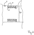
- Fig. 2 shows a schematic cross-sectional view of a tubular body which is mounted in a bore according to an embodiment.
- a tubular body 6 for mounting in a bore 9 comprises a first radially outer layer 7. Furthermore, the tubular body 6 comprises a second radially inner layer 8 made of a fiber-reinforced material. The first The radially outer layer 7 shrinks more than the second radially inner layer 8 when exposed to a temperature.
- tubular body 6 in the embodiment of FIG Fig. 2 have an optional third radially inner layer 10.
- the third layer 10 can, for example, form a running surface of an outer ring of a bearing.
- the radially outer layer 7 can be cooled in order to assemble the tubular body 6. Due to the fact that the radially outer layer 7 shrinks more when cooling than the radially inner layer 8 made of the fiber-reinforced material, the radially inner layer 8 can be compressed by the radially outer layer 7. Since the radially outer layer 7 has a smaller outer diameter d after cooling than an inner diameter D of the bore 9, the tubular body 6 can be introduced into the bore 9. When the tubular body 6 or the radially outer layer 7 has warmed up again to an ambient temperature or a temperature of the bore 9, the tubular body 6 and the bore 9 or the housing of the bore 9 can optionally be a non-positive connection with a Overlap each other.
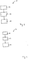
- Fig. 3 shows a schematic representation of a method for mounting a tubular body on a shaft.
- Fig. 3 shown in a method 11 for assembling a tubular body 1 with a first layer 3 and a second layer 4 made of a fiber-reinforced material on a shaft 2, the layers are arranged 12 relative to one another, so that the first layer 3 lies radially on the inside and the second layer 4 from the fiber-reinforced material lies radially on the outside.
- the radially inner layer is heated to a temperature which is higher than an ambient temperature 13.
- the tubular body is then arranged on the shaft 14.
- Fig. 4 shows a schematic representation of a method for assembling a tubular body in a bore.
- a method 15 for assembling a tubular body 6 with a first layer 7 and a second layer 8 made of a fiber-reinforced material in a bore 9 comprises arranging 16 the layers to one another.
- the layers are arranged with respect to one another in such a way that the first layer 7 lies radially on the outside and the second layer 8 made of the fiber-reinforced material lies radially on the inside.
- the radially outer layer 7 is cooled 17.
- the radially outer layer 7 is cooled to a temperature that is less than an ambient temperature.
- the tubular body 6 is then arranged 18 in the bore 18.
- tubular bodies and methods for assembling the tubular bodies can, for example, not only be used or used as a component for rolling bearings or for assembling rolling bearings, as described in the exemplary embodiments.
- the bodies or methods described could also be used as or in other machine parts or for their assembly. Examples include: sleeves, seals, gears, shaft-hub connections, etc.
Landscapes
- Engineering & Computer Science (AREA)
- General Engineering & Computer Science (AREA)
- Mechanical Engineering (AREA)
- Shafts, Cranks, Connecting Bars, And Related Bearings (AREA)
- Rolls And Other Rotary Bodies (AREA)
Description
Ausführungsbeispiele beziehen sich auf einen röhrenförmigen Körper zur Montage auf einer Welle, einen röhrenförmigen Körper zur Montage in einer Bohrung und Verfahren zur Montage des röhrenförmigen Körpers nach den unabhängigen Ansprüchen.Embodiments relate to a tubular body for mounting on a shaft, a tubular body for mounting in a bore and a method for mounting the tubular body according to the independent claims.
Bei der Montage von Bauteilen, die aus unterschiedlichen Materialien bestehen, kann es aus unterschiedlichen Gründen zu Schwierigkeiten kommen. Beispielsweise weisen faserverstärkte Kunststoffe ein anderes Temperaturverhalten auf als metallische Werkstoffe. So zeigen Bauteile aus einem faserverstärkten Kunststoff (FVK-Bauteile) je nach ihren Bestandteilen beispielsweise eine stark verringerte Wärmeausdehnung, beispielsweise gegenüber metallischen Werkstoffen, oder sogar ein Schrumpfen bei einer Wärmezufuhr. Aber nicht nur der Wärmeausdehnungskoeffizient, sondern auch eine Richtung der Ausdehnung von faserverstärkten Werkstoffen kann sich beispielsweise aufgrund des anisotropen Verhaltens von faserverstärkten Kunststoffen von einer Richtung der Ausdehnung eines metallischen Werkstoffs unterscheiden.When assembling components that are made of different materials, difficulties can arise for various reasons. For example, fiber-reinforced plastics have a different temperature behavior than metallic materials. For example, components made of fiber-reinforced plastic (FRP components) show, depending on their components, a greatly reduced thermal expansion, for example compared to metallic materials, or even shrinkage when heat is applied. However, not only the coefficient of thermal expansion, but also a direction of expansion of fiber-reinforced materials can differ from a direction of expansion of a metallic material, for example, due to the anisotropic behavior of fiber-reinforced plastics.
Diese Gründe können beispielsweise dazu führen, dass zur Montage eines Ringes aus einem faserverstärkten Kunststoff (FVK) auf einer Welle dieser nicht einfach erwärmt werden kann, um einen Durchmesser, beispielsweise einen Innendurchmesser, des Ringes zu vergrößern. Ferner kann der Ring aus dem faserverstärkten Kunststoff auch nicht einfach abgekühlt werden, um einen Durchmesser, beispielsweise einen Außendurchmesser zu verkleinern, um eine Montage in einer Bohrung oder einem Gehäuse zu ermöglichen.These reasons can lead, for example, to the fact that for the assembly of a ring made of a fiber-reinforced plastic (FRP) on a shaft, the latter cannot simply be heated in order to enlarge a diameter, for example an inner diameter, of the ring. Furthermore, the ring made of the fiber-reinforced plastic cannot simply be cooled in order to reduce a diameter, for example an outer diameter, in order to enable mounting in a bore or a housing.
Diese Schwierigkeiten können beispielsweise für einen sogenannten Hybridring aus einem faserverstärkten Kunststoff (Faserteil) und Stahl auftreten. Der Hybridring aus faserverstärktem Kunststoff und Stahl wird oft in der Form verwendet, dass der Stahlteil einen ersten Teil für die Laufbahn bildet und das Faserteil den Unterbau dazu. Aufgrund der beschriebenen unterschiedlichen Wärmeausdehnungen könnte es beispielsweise schwierig sein, den Ring mit einer Überdeckung, also einem negativen Spiel, ohne Presse auf eine Welle oder in ein Gehäuse bzw. einer Bohrung zu montieren.These difficulties can occur, for example, for a so-called hybrid ring made of a fiber-reinforced plastic (fiber part) and steel. The hybrid ring made of fiber-reinforced plastic and steel is often used in such a way that the steel part forms a first part for the career and the fiber part the substructure. Because of the different thermal expansions described, it could be difficult, for example, to mount the ring with an overlap, that is to say a negative play, without a press on a shaft or in a housing or a bore.
Bei konventionellen Lösungen kann beispielsweise zur Montage eines faserverstärkten Kunststoffringes auf einer metallischen Welle die Welle abgekühlt werden, um den faserverstärkten Kunststoffring mit einer Überdeckung zu montieren. Dies kann allerdings, je nach Größe der Welle und nach Höhe der Überdeckung sehr aufwendig und damit gegebenenfalls teuer sein.In the case of conventional solutions, for example for mounting a fiber-reinforced plastic ring on a metallic shaft, the shaft can be cooled in order to mount the fiber-reinforced plastic ring with an overlap. However, depending on the size of the shaft and the height of the overlap, this can be very complex and therefore possibly expensive.
Bei alternativen konventionellen Lösungen kann der Ring beispielsweise kalt bzw. bei einer Umgebungstemperatur auf die Welle oder in das Gehäuse eingepresst werden. Dies könnte unter Umständen zu Beschädigungen an dem Ring, an der Welle und/oder dem Gehäuse beziehungsweise der Bohrung, in die der Ring eingepresst wird, führen.In alternative conventional solutions, the ring can, for example, be pressed cold onto the shaft or into the housing at an ambient temperature. Under certain circumstances, this could lead to damage to the ring, the shaft and / or the housing or the bore into which the ring is pressed.
Es besteht daher ein Bedarf daran, ein Bauteil, das einen faserverstärkten Kunststoff umfasst, bereitzustellen, das besser montiert werden kann und ein Verfahren zur Montage eines solchen Bauteils.There is therefore a need to provide a component comprising a fiber-reinforced plastic that is easier to assemble and a method for assembling such a component.
Diesem Bedarf tragen die röhrenförmigen Körper und die Verfahren nach den unabhängigen Ansprüchen Rechnung.The tubular bodies and the methods according to the independent claims meet this need.
Ausführungsbeispiele betreffen einen röhrenförmigen Körper zur Montage auf einer Welle. Der röhrenförmige Körper umfasst eine erste radial innen liegende Schicht. Ferner umfasst der röhrenförmige Körper eine zweite radial außen liegende Schicht aus einem faserverstärkten Material. Die erste radial innen liegende Schicht dehnt sich bei einem Einwirken einer Temperatur stärker aus, als die zweite radial außen liegende Schicht.Embodiments relate to a tubular body for mounting on a shaft. The tubular body comprises a first radially inner layer. Furthermore, the tubular body comprises a second radially outer layer made of a fiber-reinforced material. When a temperature is applied, the first radially inner layer expands more than the second radially outer layer.
Dadurch, dass der röhrenförmige Körper eine radial innen liegende Schicht aufweist, die sich bei einem Einwirken einer Temperatur stärker ausdehnt als die zweite radial außen liegende Schicht, könnte beispielsweise ermöglicht werden, dass die Montage eines Ringes, der zumindest teilweise aus faserverstärktem Kunststoff besteht bzw. diese umfasst, auf einer Welle mit einer Überdeckung ohne eine Presse ermöglicht werden kann. Mit anderen Worten ausgedrückt, kann dadurch beispielsweise erreicht werden, dass der röhrenförmige Körper mit einem negativen Spiel in eine radiale Richtung auf der Welle montiert werden kann. Unter Umständen könnte dies ermöglicht werden, weil sich die radial innen liegende Schicht ausdehnt und dabei ggf. die radial außen liegende faserverstärkte Schicht mit aus-dehnen kann.The fact that the tubular body has a radially inner layer which expands more when the action of a temperature than the second radially outer layer could, for example, enable the assembly of a ring which consists at least partially of fiber-reinforced plastic or this includes, on a shaft with an overlap without a press. In other words, it can be achieved, for example, that the tubular body can be mounted on the shaft with a negative play in a radial direction. Under certain circumstances, this could be made possible because the radially inner layer expands and, if necessary, the radially outer fiber-reinforced layer can also expand.
Ein röhrenförmiger Körper kann beispielsweise jedwedes Bauteil sein, das eine Bohrung aufweist. Beispielsweise kann ein röhrenförmiger Körper ein Zylinder sein, aus dem ein konzentrisch zu dem Zylinder angeordneter zweiter Zylinder entfernt wurde. Beispiele für einen röhrenförmigen Körper sind ein Ring, ein Rohr, eine Manschette, etc. Beispielsweise kann der röhrenförmige Körper jedwede Querschnittsfläche aufweisen. Beispiele können sein: Kreisringscheibe, einen Vieleckringscheiben, Rechteckringscheibe, ovaler Ring, etc.A tubular body can be, for example, any component that has a bore. For example, a tubular body can be a cylinder from which a second cylinder arranged concentrically to the cylinder has been removed. Examples of a tubular body are a ring, a tube, a sleeve, etc. For example, the tubular body can have any cross-sectional area. Examples can be: circular washer, a polygonal washer, rectangular washer, oval ring, etc.
Eine radial innen liegende Schicht kann beispielsweise jedwedes Bauteil sein, das auf einem kleineren Durchmesser angeordnet ist als die radial außen liegende Schicht. Beispielsweise kann die radial innen liegende Schicht ein Ring oder ein Hohlzylinder sein. Analog kann die radial außen liegende Schicht beispielsweise jedwedes Bauteil sein, das auf einem größeren Durchmesser angeordnet ist, als die radial innen liegende Schicht. Beispielsweise kann die radial außen liegende Schicht als Hohlzylinder oder Ring ausgebildet sein. Bei einigen weiteren Ausführungsbeispielen sind die radial innen liegende Schicht und die radial außen liegende Schicht konzentrisch zueinander und/oder konzentrische zu dem röhrenförmigen Körper angeordnet. Dadurch könnte ggf. ermöglicht werden, dass der röhrenförmige Körper als ein rotationssymmetrisches Bauteil ausgebildet ist. Die radial innen liegende Schicht kann beispielweise in einem montierten Zustand direkt an der Welle anliegen. Beispielsweise kann die radial außenliegende Schicht direkt an der radial innenliegenden Schicht anliegen, also beispielsweise nicht durch eine andere Schicht beabstandet sein.A radially inner layer can be, for example, any component that is arranged on a smaller diameter than the radially outer layer. For example, the radially inner layer can be a ring or a hollow cylinder. Analogously, the radially outer layer can be, for example, any component that is arranged on a larger diameter than the radially inner layer. For example, the radially outer layer can be designed as a hollow cylinder or ring. In some further exemplary embodiments, the radially inner layer and the radially outer layer are arranged concentrically to one another and / or concentrically to the tubular body. This could possibly make it possible for the tubular Body is designed as a rotationally symmetrical component. The radially inner layer can, for example, lie directly against the shaft in an assembled state. For example, the radially outer layer can lie directly on the radially inner layer, that is to say, for example, not be spaced apart by another layer.
Eine Temperatur unter deren Einwirken sich die radial innen liegende Schicht stärker ausdehnt als die zweite radial außen liegende Schicht, ist eine Temperatur, die gegenüber einer Umgebungstemperatur oder einer Raumtemperatur erhöht ist. Beispielsweise kann die Temperatur in einem Bereich liegen, der einen Anfangswert und einen Endwert aufweist. Beispielsweise kann ein Anfangswert des Bereichs 30°C, 40°C, 50°C, 60°C, 70°C oder 80°C, 90°C sein, beispielsweise kann ein Endwert des Bereichs 400°C; 250°C, 220°C, 200°C, 190°C, 180°C, 170°C, 160°C, 150°C, 140°C, 130°C, 120°C, 110°C, 100°C, 90°C oder 80°C sein.A temperature under the action of which the radially inner layer expands more than the second radially outer layer is a temperature that is higher than an ambient temperature or a room temperature. For example the temperature may be in a range that has an initial value and an end value. For example, an initial value of the range can be 30 ° C, 40 ° C, 50 ° C, 60 ° C, 70 ° C or 80 ° C, 90 ° C, for example an end value of the range can be 400 ° C; 250 ° C, 220 ° C, 200 ° C, 190 ° C, 180 ° C, 170 ° C, 160 ° C, 150 ° C, 140 ° C, 130 ° C, 120 ° C, 110 ° C, 100 ° C, 90 ° C or 80 ° C.
Bei einigen weiteren Ausführungsbeispielen ist ein Verhältnis aus einer Wandstärke der radial innen liegenden Schicht und einer Wandstärke der radial außen liegenden Schicht größer oder gleich 0,1; 0,2; 0,3; 0,5 oder 1. Beispielsweise kann das Verhältnis maximal einen Wert aufweisen, der in einem Wertebereich mit einem Anfangs und oder einen Endwert liegt, die 0,2; 0,5; 0,6; 0,7; 0,75; 0,8; 0,9 und/oder 1 betragen. Dadurch könnte beispielsweise erreicht werden, dass sich die radial innen liegende Schicht bei einem Einwirken einer Temperatur stärker ausdehnt als die radial außen liegende Schicht. Mit anderen Worten ausgedrückt, kann die radial innen liegende Schicht eine größere Wandstärke als die radial außen liegende Schicht aufweisen. Bei einigen weiteren Ausführungsbeispielen können die radial innen liegende Schicht und die radial außen liegende Schicht in axialer Richtung die gleiche Breite aufweisen. Entsprechend kann ggf. die radial innen liegende Schicht dicker ausgebildet sein, als die radial außen liegende Schicht.In some further exemplary embodiments, a ratio of a wall thickness of the radially inner layer and a wall thickness of the radially outer layer is greater than or equal to 0.1; 0.2; 0.3; 0.5 or 1. For example, the ratio can have a maximum of a value which lies in a range of values with an initial and / or an end value which is 0.2; 0.5; 0.6; 0.7; 0.75; 0.8; 0.9 and / or 1. It could be achieved, for example, that the radially inner layer expands more when the temperature is applied than the radially outer layer. In other words, the radially inner layer can have a greater wall thickness than the radially outer layer. In some further exemplary embodiments, the radially inner layer and the radially outer layer can have the same width in the axial direction. Correspondingly, the radially inner layer can possibly be made thicker than the radially outer layer.
Beispielsweise können die Schichten miteinander verbunden sein. Beispielsweise können die Schichten kraft-und/oder formschlüssig miteinander verbunden sein. Beispielsweise können die Schichten miteinander verklebt sein. Bei weiteren Ausführungsbeispielen können die Schichten lösbar miteinander verbunden sein. Dadurch könnte beispielsweise ermöglicht werden, dass die radial innenliegende Schicht nach der Montage wieder entfernt werden kann.For example, the layers can be connected to one another. For example, the layers can be connected to one another in a non-positive and / or positive manner. For example, the layers can be glued together. In further exemplary embodiments, the layers can be releasably connected to one another. This could make it possible, for example, for the radially inner layer to be removed again after assembly.
Bei einigen weiteren Ausführungsbeispielen kann die radial innen liegende Schicht einen Außendurchmesser aufweisen, der im Wesentlichen einem Innendurchmesser einer Innenbohrung der radial außen liegenden Schicht entspricht. Dadurch könnte in manchen Fällen ermöglicht werden, dass die radial außen liegende Schicht zu einer Verbindung mit der radial innen liegenden Schicht auf einen Außenumfang der radial innen liegenden Schicht geschoben werden kann. Beispielsweise können ein Außendurchmesser eines Außenumfangs der radial innen liegenden Schicht so zu einer Innenbohrung bzw. einem Innendurchmesser der radial außen liegenden Schicht dimensioniert sein, dass diese ein radiales Spiel zueinander aufweisen. Das radiale Spiel kann ggf. so dimensioniert sein, dass die radial außen liegende Schicht und die radial innen liegende Schicht beispielsweise bei Raumtemperatur einen Schiebesitz zueinander aufweisen. Dadurch könnten ggf. ermöglicht werden, dass die radial innen liegende Schicht beispielsweise bei Umgebungstemperatur in eine Bohrung der radial außen liegenden Schicht geschoben werden kann.In some further exemplary embodiments, the radially inner layer can have an outer diameter which essentially corresponds to an inner diameter of an inner bore of the radially outer layer. In some cases, this could make it possible for the radially outer layer to be pushed onto an outer circumference of the radially inner layer to form a connection with the radially inner layer. For example, an outer diameter of an outer circumference of the radially inner layer can be dimensioned to form an inner bore or an inner diameter of the radially outer layer such that it is a radial one Show play to each other. The radial play can, if necessary, be dimensioned such that the radially outer layer and the radially inner layer have a sliding fit to one another, for example at room temperature. This could possibly make it possible for the radially inner layer to be pushed into a hole in the radially outer layer, for example at ambient temperature.
Bei einigen weiteren Ausführungsbeispielen umfasst die radial innen liegende Schicht einen metallischen Werkstoff. So könnte ggf. auf einfache Art und Weise erreicht werden, dass sich die radial innen liegende Schicht stärker ausdehnt als die radial außen liegende Schicht. Beispielsweise kann der metallische Werkstoff ein Stahl sein. Dadurch könnte beispielsweise ermöglicht werden, dass die radial innen liegende Schicht aus einem gut bearbeitbaren, kostengünstigen, mit Umgebungsmaterialien chemisch verträglichen oder verschleißverhindernden Material herstellbar sein kann. Weitere Beispiele für metallische Werkstoffe sind Eisen, Chrom, Aluminium, Kupfer, und/oder Legierungen die diese oder andere metallische Werkstoffe umfassen.In some further exemplary embodiments, the radially inner layer comprises a metallic material. It could thus be achieved in a simple manner that the radially inner layer expands more than the radially outer layer. For example, the metallic material can be steel. This could make it possible, for example, for the radially inner layer to be able to be produced from an easily machinable, cost-effective material that is chemically compatible with environmental materials or prevents wear. Further examples of metallic materials are iron, chromium, aluminum, copper, and / or alloys which comprise these or other metallic materials.
Bei einigen weiteren Ausführungsbeispielen kann die radial innen liegende Schicht einen Werkstoff umfassen, der einen größeren Wärmeausdehnungskoeffizienten aufweist als der Werkstoff oder ein Material der radial außen liegenden Schicht. Dadurch könnte evtl. ermöglicht werden, dass dich die radial innen liegende Schicht stärker ausdehnt als die radial außen liegende Schicht.In some further exemplary embodiments, the radially inner layer can comprise a material that has a greater coefficient of thermal expansion than the material or a material of the radially outer layer. This could possibly make it possible for the radially inner layer to expand more than the radially outer layer.
Bei einigen weiteren Ausführungsbeispielen kann das faserverstärkte Material jedwedes faserverstärkte Material sein. Beispielsweise kann das faserverstärkte Material ein Faserverbundkunststoff (FVK), ein kohlefaserverstärkter Kunststoff (CFK), ein glasfaserverstärkter Kunststoff (GFK), ein aramidfaserverstärkter Kunststoff (AFK), ein naturfaserverstärketer Kunststoff (NFK) und/oder ein Faser-Keramik-Verbund (CMC) sein. Dadurch könnte unter Umständen ermöglicht werden, dass der Körper ein geringes Gewicht aufweist. Dadurch könnte ggf. bei Fahrzeugen die den röhrenförmigen Körper umfassen ein geringere CO2 ein Ausstoß bewirkt werden. Ferner könnte das leichtere Bauteil ggf. ein geringeres Trägheitsmoment aufweisen leichter Beschleunigt werden. Ebenfalls könnte unter Umständen eine Montage oder Demontage des Körpers erleichtert werden. Ein solcher Hybridring könnte beispielsweise lange, beinahe endlose Verstärkungsfasern wie Kohle, Glas oder Aramidfasern beinhalten, die durch ein Wickelverfahren durch Rotation des Grundkörpers um eine Achse aufgewickelt werden. Diese Fasern können ggf. in einem duroplastischen oder thermoplastischen Grundmaterial/Matrix eingebettet sein, das als Harz-System ausgebildet sein kann. Beispielsweise kann das faserverstärkte Material eine Faser aufweisen, die länger als 1 mm 20 mm, 30 mm, 40, mm 50 mm ist.In some other embodiments, the fiber reinforced material can be any fiber reinforced material. For example, the fiber-reinforced material can be a fiber composite plastic (FVK), a carbon fiber reinforced plastic (CFK), a glass fiber reinforced plastic (GFK), an aramid fiber reinforced plastic (AFK), a natural fiber reinforced plastic (NFK) and / or a fiber-ceramic composite (CMC) his. This could possibly make it possible for the body to be light in weight. This could possibly result in a lower CO 2 emission in vehicles which comprise the tubular body. Furthermore, the lighter component could possibly have a lower moment of inertia and be accelerated more easily. Assembly or disassembly of the body could also be facilitated under certain circumstances. Such a hybrid ring could, for example, contain long, almost endless reinforcing fibers such as carbon, glass or aramid fibers, which are produced by a winding process by rotation of the base body are wound around an axis. These fibers can optionally be embedded in a thermosetting or thermoplastic base material / matrix, which can be designed as a resin system. For example, the fiber-reinforced material can have a fiber that is longer than 1 mm 20 mm, 30 mm, 40, mm 50 mm.
Bei einigen weiteren Ausführungsbeispielen weist die radial außen liegende Schicht einen thermischen Ausdehnungskoeffizienten auf, der in einem Wertebereich mit einem Anfangswert und eine Endwert liegt. Der Endwert kann beispielsweise zwischen 0,1 · 10-5 1/k oder 1,5 · 10-5 1/k betragen. Der Endwert kann beispielsweise 1,5 · 10-5 1/k; 2,0 · 10-5 1/k oder 2,5 · 10-5 1/k betragen. Dadurch kann beispielsweise erreicht werden, dass sich die radial außen liegende Schicht bei einem Einwirken einer Temperatur weniger stark ausdehnt als die radial innen liegende Schicht. Bei einigen weiteren Ausführungsbeispielen kann die radial innen liegende Schicht einen thermischen Ausdehnungskoeffizienten aufweisen, der in einem Wertebereich mit einem Anfangswert und einem Endwert liegen kann. Beispielsweise kann der Anfangswert 0,1 · 10-5 1/k; 1,0 · 10-5 1/k; 1,2 · 10-5 1/k; oder 1,3 · 10-5 1/k betragen. Der Endwert kann beispielsweise 1,3 · 10-5 1/k; 1,4 · 10-5 1/k; 1,5 · 10-5 1/k oder 2,5 · 10-5 1/k betragen. So könnte gegebenenfalls erreicht werden, dass sich die radial innen liegende Schicht bei einem Einwirken einer Temperatur stärker ausdehnt als die zweite radial außen liegende Schicht.In some further exemplary embodiments, the radially outer layer has a coefficient of thermal expansion which lies in a range of values with an initial value and an end value. The final value can be, for example, between 0.1 · 10 -5 1 / k or 1.5 · 10 -5 1 / k. The final value can be, for example, 1.5 · 10 -5 1 / k; 2.0 x 10 -5 1 / k or 2.5 x 10 -5 1 / k. In this way it can be achieved, for example, that the radially outer layer expands less strongly than the radially inner layer when exposed to a temperature. In some further exemplary embodiments, the radially inner layer can have a coefficient of thermal expansion which can be in a range of values with an initial value and an end value. For example, the initial value may be 0.1 x 10 -5 1 / k; 1.0 x 10 -5 1 / k; 1.2 x 10 -5 1 / k; or 1.3 · 10 -5 1 / k. The final value can be, for example, 1.3 · 10 -5 1 / k; 1.4 x 10 -5 1 / k; 1.5 x 10 -5 1 / k or 2.5 x 10 -5 1 / k. In this way, it could possibly be achieved that the radially inner layer expands more when the temperature acts than the second radially outer layer.
Bei einigen weiteren Ausdehnungsbeispielen weist die radial außen liegende Schicht eine Querkontraktionszahl in einem Wertebereich auf. Der Wertebereich kann einen Anfangswert und einen Endwert aufweisen. Der Endwert oder der Anfangswert kann beispielsweise jeweils 0; 0,1; 0,4; 0,6; 0,8; 1,0; 1,2; 1,4; 1,6; 1,8; 2,0; 2,2; 2,4 oder 2,5 betragen. Dadurch könnte beispielsweise erreicht werden, dass sich die radial außen liegende Schicht weniger stark ausdehnt als die radial innen liegende Schicht. Bei der Querkontraktionszahl, auch Poisson'sche Zahl genannt, handelt es sich um einen dimensionslosen Wert, der die Deformation eines festen Körpers bei annähernd gleichem Volumen beschreibt. Beispielsweise kann die Querkontraktionszahl das Verhalten eines Festkörpers unter dem Einfluss einer Zugkraft bzw. einer Druckkraft beschreiben.In some further examples of expansion, the radially outer layer has a transverse contraction number in a range of values. The range of values can have an initial value and an end value. The end value or the initial value can, for example, each be 0; 0.1; 0.4; 0.6; 0.8; 1.0; 1.2; 1.4; 1.6; 1.8; 2.0; 2.2; 2.4 or 2.5. In this way it could be achieved, for example, that the radially outer layer expands less than the radially inner layer. The transverse contraction number, also called the Poisson number, is a dimensionless value that describes the deformation of a solid body with approximately the same volume. For example, the transverse contraction number can describe the behavior of a solid under the influence of a tensile force or a compressive force.
Bei einigen weiteren Ausführungsbeispielen weist die radial innen liegende Schicht eine Querkontraktionszahl auf die in einem Wertebereich zwischen 0,2 und 0,4 liegt. Beispielsweise kann die Querkontraktionszahl 0,3 sein. In manchen Fällen könnte so erreicht werden, dass sich die radial innen liegende Schicht bei einem Einwirken einer Temperatur stärker ausdehnt, als die radial außen liegende Schicht.In some further exemplary embodiments, the radially inner layer has a transverse contraction number which lies in a range of values between 0.2 and 0.4. For example the transverse contraction number can be 0.3. In some cases it could be achieved that the radially inner layer expands more when exposed to a temperature than the radially outer layer.
Bei einigen weiteren Ausführungsbeispielen weist die radial außen liegende Schicht einen Elastizitätsmodul auf, der in einem Bereich zwischen 100.000 MPa und 600.000 MPa liegt, beispielsweise bei ca. 210.000 MPa. So könnte ggf. ein ausreichendes Verformungsverhalten der radial außen liegenden Schicht während der Montage mittels Wärme ermöglicht werden. Unter Umständen könnte so ggf. die Gefahr miniert werden, dass die radial außen liegende Schicht bei der Montage reißt.In some further exemplary embodiments, the radially outer layer has a modulus of elasticity which is in a range between 100,000 MPa and 600,000 MPa, for example approximately 210,000 MPa. If necessary, sufficient deformation behavior of the radially outer layer could be made possible during assembly by means of heat. Under certain circumstances, the risk could be minimized that the radially outer layer tears during assembly.
Bei einigen weiteren Ausführungsbeispielen weist die radial innen liegende Schicht einen Elastizitätsmodul auf, der in einem Bereich zwischen 200.000 MPa und 250.000 MPa liegt, beispielsweise bei ca. 210.000 MPa. So kann könnte beispielsweise erreicht werden, dass die radial innen liegende Schicht eine ausreichende Verformungsfähigkeit zur Montage mit Wärme hat.In some further exemplary embodiments, the radially inner layer has a modulus of elasticity which is in a range between 200,000 MPa and 250,000 MPa, for example approximately 210,000 MPa. For example, it could be achieved that the radially inner layer has sufficient deformability for assembly with heat.
Bei einigen weiteren Ausführungsbeispielen ist der röhrenförmige Körper ein Innenring eines Lagers. Unter Umständen könnte dadurch ermöglicht werden, dass ein sogenanntes Faserverbund-Leichtbau-Lager besser montiert werden kann. Beispielsweise kann der röhrenförmige Körper eine dritte, radial außen liegende Schicht aufweisen. Diese dritte radial außen liegende Schicht kann beispielsweise eine Lauffläche ausbilden. Dadurch könnte beispielsweise ermöglicht werden, dass der Innenring eine gleichmäßige Lauffläche aufweist. Beispielsweise kann die dritte radial außen liegende Schicht aus einem metallischen oder keramischen Werkstoff hergestellt sein oder direkt in das Material der radial außen liegende Schicht eingearbeitet sein. So könnte beispielsweise ermöglicht werden, dass die Lauffläche sehr stabil ist. Mit anderen Worten ausgedrückt, könnte in manchen Fällen ein Wälzlagerring oder Gleitlagerring aus einem Faserverbundmaterial und einem Metall bereitgestellt werden, bei dem es möglich sein könnte, den Außen- oder Innendurchmesser durch Erwärmen oder Kühlen zu verändern. Durch diese Veränderung könnte beispielsweise eine Montage eines röhrenförmigen Körpers aus einem faserverstärkten Kunststoff bzw. der zumindest als einen Werkstoff einen faserverstärkten Kunststoff umfasst, auf einer Welle mit einer Überdeckung, ohne Verwendung einer Presse, ermöglicht werden.In some other embodiments, the tubular body is an inner ring of a bearing. Under certain circumstances, this could make it possible for a so-called fiber composite lightweight bearing to be better assembled. For example, the tubular body can have a third, radially outer layer. This third radially outer layer can, for example, form a tread. This could make it possible, for example, for the inner ring to have a uniform running surface. For example, the third radially outer layer can be made of a metallic or ceramic material or can be incorporated directly into the material of the radially outer layer. For example, the tread could be made very stable. In other words, in some cases, a rolling bearing ring or sliding bearing ring made of a fiber composite material and a metal could be provided, in which it could be possible to change the outside or inside diameter by heating or cooling. This change could, for example, enable a tubular body made of a fiber-reinforced plastic or, at least as one material, a fiber-reinforced plastic to be mounted on a shaft with an overlap without using a press.
Einige Ausführungsbeispiele betreffen einen röhrenförmigen Körper zur Montage in einer Bohrung. Der röhrenförmige Körper umfasst eine erste radial außen liegende Schicht. Ferner umfasst der röhrenförmige Körper eine zweite radial innen liegende Schicht aus einem faserverstärkten Material. Die erste radial außen liegende Schicht schrumpft bei einem Einwirken einer Temperatur stärker als die zweite radial innen liegende Schicht. So kann gegebenenfalls ermöglicht werden, dass der ringförmige Körper in einem Gehäuse oder einer Bohrung, ggf. mit einer Überdeckung, montiert werden kann. Dabei kann eine Temperatur, die auf den Körper bzw. die radial außen liegende Schicht einwirkt ggf. geringer als eine Umgebungstemperatur sein.Some embodiments relate to a tubular body for mounting in a bore. The tubular body comprises a first radially outer layer. Furthermore, the tubular body comprises a second radially inner layer made of a fiber-reinforced material. The first radially outer layer shrinks more when exposed to a temperature than the second radially inner layer. This can make it possible, if necessary, for the annular body to be mounted in a housing or a bore, possibly with an overlap. In this case, a temperature which acts on the body or on the radially outer layer may be lower than an ambient temperature.
Beispielsweise liegt die Temperatur in einem Wertebereich der einen Anfangswert und einen Endwerte aufweist. Der Anfangswert oder der Endwert können jeweils -200°C; -196 °C; -150°C; -100°C; -78°C; -50° oder 0°C sein.For example, the temperature is in a range of values that has an initial value and an end value. The start value or the end value can each be -200 ° C; -196 ° C; -150 ° C; -100 ° C; -78 ° C; -50 ° or 0 ° C.
Bei einigen weiteren Ausführungsbeispielen umfasst die radial außen liegende Schicht einen metallischen Werkstoff. So könnte unter Umständen auf einfache Art und Weise bewirkt werden, dass die radial außen liegende Schicht bei einem Einwirken einer Temperatur stärker schrumpft als die radial innen liegende Schicht. Beispiele für metallische Werkstoffe sind Eisen, Chrom, Aluminium, Kupfer, und/oder Legierungen die diese oder andere metallische Werkstoffe umfassen.In some further exemplary embodiments, the radially outer layer comprises a metallic material. Under certain circumstances, it could easily be caused that the radially outer layer shrinks more when exposed to a temperature than the radially inner layer. Examples of metallic materials are iron, chromium, aluminum, copper, and / or alloys which comprise these or other metallic materials.
Bei einigen weiteren Ausführungsbeispielen ist der ringförmige Körper ein Außenring eines Lagers. Beispielsweise kann der ringförmige Körper eine dritte, radial innen liegende Schicht aufweisen, die die Lauffläche ausbildet. So könnte beispielsweise ermöglicht werden, dass der Außenring eine stabile Lauffläche aufweist. Beispielsweise kann die dritte, radial innen liegende Schicht aus einem metallischen oder keramischen Werkstoff hergestellt sein oder direkt in das Material der radial außen liegende Schicht eingearbeitet sein. So könnte beispielsweise eine stabile Lauffläche bereitgestellt werden. Mit anderen Worten ausgedrückt, könnte ein Wälzlagerring oder Gleitlagerring, beispielsweise ein Außenring, bereitgestellt werden aus einem Faserverbundmaterial und einem Metall, bei dem es möglich sein könnte, den Außendurchmesser durch Kühlen zu verändern. Durch diese Veränderung könnte beispielsweise eine Montage eines Ringes aus einen faserverstärkten Kunststoff bzw. der zumindest als einen Werkstoff einen faserverstärkten Kunststoff umfasst in ein Gehäuse oder eine Bohrung mit einer Überdeckung, ohne eine Presse, zu verwenden möglich sein.In some other embodiments, the annular body is an outer ring of a bearing. For example, the annular body can have a third, radially inner layer that forms the tread. For example, it could be made possible for the outer ring to have a stable running surface. For example, the third, radially inner layer can be made of a metallic or ceramic material or can be incorporated directly into the material of the radially outer layer. For example, a stable tread could be provided. In other words, a rolling bearing ring or plain bearing ring, for example an outer ring, could be provided from a fiber composite material and a metal, in which it could be possible to change the outer diameter by cooling. As a result of this change, for example, an assembly of a ring made of a fiber-reinforced plastic or which comprises at least one material as a fiber-reinforced plastic in a housing or a bore with a cover, without using a press.
Bei einigen weiteren Ausführungsbeispielen umfasst der röhrenförmigen Körper eine Temperiereinrichtung, die ausgebildet ist, den Körper zu erwärmen und/oder abzukühlen so dass das Auszudehnen bzw. Schrumpfen der Schichten bewirkt werden kann. Dadurch könnte ggf. die Montage des Körpers vereinfacht werden. Beispielsweise kann die Temperiereinrichtung eine Heizung oder ein Kühlelement sein.In some further exemplary embodiments, the tubular body comprises a temperature control device which is designed to heat and / or cool the body so that the layers can be expanded or shrunk. This could possibly simplify the assembly of the body. For example, the temperature control device can be a heater or a cooling element.
Einige Ausführungsbeispiele betreffen ein Verfahren zur Montage eines röhrenförmigen Körpers auf einer Welle. Der Körper weist eine erste Schicht auf. Ferner weist der Körper eine zweite Schicht aus einem faserverstärkten Material auf. Bei dem Verfahren werden zuerst die erste Schicht und die zweite Schicht so zueinander angeordnet, dass die erste Schicht in einem radial inneren Bereich der zweiten Schicht aus dem faserverstärkten Werkstoff liegt. Der röhrenförmige Körper und/oder die radial innen liegende Schicht werden auf eine Temperatur, die gegenüber einer Umgebungstemperatur erhöht ist, erwärmt. Anschließend wird der röhrenförmige Körper auf einer Welle montiert. Beispielsweise kann die erste Schicht konzentrisch zu der zweiten Schicht angeordnet werden. Ergänzend oder alternativ kann die erste Schicht in einer Bohrung der zweiten Schicht angeordnet werden. Dadurch könnte beispielsweise ermöglicht werden, dass ein faserverstärkter Ring durch die radial innen angeordnete Schicht so aufgeweitet und/oder gedehnt werden kann, dass er auf einer Welle montiert werden kann. Die innen liegende Schicht könnte quasi als ein Adapter, mit dem der Presssitz mit der Welle hergestellt werden kann und/oder gleichzeitig der faserverstärkte Ring gedehnt werden kann, verwendet werden.Some exemplary embodiments relate to a method for mounting a tubular body on a shaft. The body has a first layer. Furthermore, the body has a second layer made of a fiber-reinforced material. In the method, the first layer and the second layer are first arranged with respect to one another such that the first layer lies in a radially inner region of the second layer made of the fiber-reinforced material. The tubular body and / or the radially inner layer are heated to a temperature which is higher than an ambient temperature. The tubular body is then mounted on a shaft. For example, the first layer can be arranged concentrically with the second layer. Additionally or alternatively, the first layer can be arranged in a bore in the second layer. This could make it possible, for example, for a fiber-reinforced ring to be expanded and / or stretched by the radially inner layer so that it can be mounted on a shaft. The inner layer could be used as an adapter, with which the press fit can be made with the shaft and / or at the same time the fiber-reinforced ring can be stretched.
Beispielsweise kann die radial außen liegende Schicht aus dem faserverstärktem Material eine Innenbohrung aufweisen, die einen Durchmesser aufweist, der im Wesentlichen einem Außendurchmesser der radial innen liegenden Schicht entspricht. Beispielsweise könnten die beiden Durchmesser so zueinander dimensioniert sein, dass die beiden Bauteile in radialer Richtung ein Spiel zueinander aufweisen. Durch dieses Spiel könnte ermöglicht werden, dass die radial innen liegende Schicht bei Zimmertemperatur beispielsweise bei Raumtemperatur in die radial außen liegende Schicht, beispielsweise von Hand geschoben werden kann. Dadurch könnte beispielsweise ermöglicht werden, dass beim Fügen bzw. einer Montage der radial innen liegenden Schicht in die radial außen liegende Schicht keines der beiden Bauteile beschädigt wird. Anschließend kann der röhrenförmige Körper beispielsweise aber auch hauptsächlich die radial innen liegende Schicht, erwärmt werden. Unter Umständen könnte einer Erwärmung der radial innen liegenden Schicht auch zu einem Erwärmen der radial außen liegenden Schicht führen. Dies könnte beispielsweise gewünscht sein oder hingenommen werden.For example, the radially outer layer made of the fiber-reinforced material can have an inner bore that has a diameter that essentially corresponds to an outer diameter of the radially inner layer. For example, the two diameters could be dimensioned with respect to one another such that the two components have a play with one another in the radial direction. This play could make it possible for the radially inner layer to be pushed into the radially outer layer, for example by hand, at room temperature, for example at room temperature. This could make it possible, for example, that when the radially inner layer is joined or installed in the radially outer layer, none of the two components is damaged. Then the tubular body, for example, but also mainly the radially inner layer, can be heated. Under certain circumstances, heating the radially inner layer could also lead to heating the radially outer layer. This could be desired or accepted, for example.
Mit anderen Worten ausgedrückt, könnte beispielsweise durch das Erwärmen der radial innen liegenden Schicht bewirkt werden, dass sich diese in radiale Richtung ausdehnt. Das könnte bedeuten, dass sich eine Bohrung (in axialer Richtung) der radial innen liegenden Schicht ebenfalls in radiale Richtung vergrößert bzw. einen zumindest vorübergehend größeren Durchmesser erhält. Ferner könnte ebenfalls bewirkt werden, dass sich auch ein Au-ßenumfang der radial innen liegenden Schicht in radial Richtung ausdehnt bzw. vergrößert. Dadurch könnte bspw. erreicht werden, dass die radial außen liegende Schicht aus dem faserverstärkten Werkstoff gedehnt wird. Ferner könnte in manchen Fällen die radial innen liegende Schicht durch die radial außen liegende Schicht eingeschnürt werden. Dadurch, dass sich die Innenbohrung der radial innen liegenden Schicht vergrößert, könnte beispielsweise ermöglicht werden, dass die radial innen liegende Schicht und damit der ganze röhrenförmige Körper auf eine Welle geschoben werden kann. Nach einem Abkühlen der radial innen liegenden Schicht geht die Bohrung bzw. der Bohrungsquerschnitt wieder auf seine ursprüngliche Größe zurück. So könnt ggf. eine kraftschlüssige Verbindung zwischen der Welle und der inneren Bohrung hergestellt. Dadurch könnte der faserverstärkte ggf. Ring kraftsschlüssig auf der Welle montiert werden.In other words, heating the radially inner layer could, for example, cause it to expand in the radial direction. This could mean that a bore (in the axial direction) of the radially inner layer also increases in the radial direction or at least temporarily has a larger diameter. Furthermore, it could also be caused that an outer circumference of the radially inner layer also expands or enlarges in the radial direction. This could be achieved, for example, by stretching the radially outer layer made of the fiber-reinforced material. Furthermore, in some cases the radially inner layer could be constricted by the radially outer layer. Because the inner bore of the radially inner layer increases, it could be possible, for example, for the radially inner layer and thus the entire tubular body to be pushed onto a shaft. After the radially inner layer has cooled, the bore or the bore cross section returns to its original size. If necessary, a non-positive connection can be established between the shaft and the inner bore. As a result, the fiber-reinforced ring, if applicable, could be non-positively mounted on the shaft.
Bei einigen weiteren Ausführungsbeispielen wird der röhrenförmig Körper beispielsweise auf eine Temperatur erwärmt, die in einem Bereich liegt, der einen Anfangswert und einen Endwert aufweist. Beispielsweise kann ein Anfangswert des Bereichs 30°C, 40°C, 50°C, 60°C, 70°C oder 80°C, 90°C sein, beispielsweise kann ein Endwert des Bereichs 250°C, 220°C, 200°C, 190°C, 180°C, 170°C, 160°C, 150°C, 140°C, 130°C, 120°C, 110°C, 100°C, 90°C oder 80°C sein.In some other embodiments, the tubular body is heated, for example, to a temperature that is in a range that has an initial value and an end value. For example, an initial value of the range can be 30 ° C, 40 ° C, 50 ° C, 60 ° C, 70 ° C or 80 ° C, 90 ° C, for example an end value of the range 250 ° C, 220 ° C, 200 ° C, 190 ° C, 180 ° C, 170 ° C, 160 ° C, 150 ° C, 140 ° C, 130 ° C, 120 ° C, 110 ° C, 100 ° C, 90 ° C or 80 ° C his.
Einige Ausführungsbeispiele betreffen ein Verfahren zur Montage eines röhrenförmigen Körpers mit einer ersten Schicht und einer zweiten Schicht aus einem faserverstärkten Material in eine Bohrung. Dabei werden die Schichten beispielsweise konzentrisch zueinander angeordnet, sodass die erste Schicht radial außen liegt und die zweite Schicht aus dem faserverstärkten Werkstoff radial innen liegt. Anschließend wird die radial außen liegende Schicht abgekühlt. Dabei wird die radial außen liegende Schicht auf eine Temperatur, die kleiner als eine Umgebungstemperatur ist, abgekühlt. Anschließend wird der röhrenförmige Körper in der Bohrung angeordnet. So könnte beispielsweise ein röhrenförmiger Körper, der einen faserverstärkten Werkstoff umfasst, auf einfache Art und Weise, beispielsweise ohne eine Presse in einer Bohrung, beispielsweise eines Gehäuses, montiert werden.Some embodiments relate to a method for assembling a tubular body with a first layer and a second layer made of a fiber-reinforced material into a bore. The layers are arranged concentrically to one another, for example, so that the first layer lies radially on the outside and the second layer consists of the fiber-reinforced one Material lies radially inside. Then the radially outer layer is cooled. The radially outer layer is cooled to a temperature that is less than an ambient temperature. The tubular body is then placed in the bore. For example, a tubular body, which comprises a fiber-reinforced material, could be mounted in a simple manner, for example without a press, in a bore, for example in a housing.
Weitere vorteilhafte Ausgestaltungen werden nachfolgend anhand von in den Zeichnungen dargestellten Ausführungsbeispielen, auf welcher Ausführungsbeispiele jedoch nicht beschränkt sind, näher beschrieben.Further advantageous embodiments are described in more detail below with reference to exemplary embodiments shown in the drawings, to which exemplary embodiments are not limited, however.
So zeigen die Figuren schematisch die nachfolgenden Ansichten:
- Fig. 1
- zeigt eine schematische Querschnittsdarstellung eines röhrenförmigen Körpers, der auf einer Welle montiert ist nach einem Ausführungsbeispiel;
- Fig. 2
- zeigt eine schematische Querschnittsdarstellung eines röhrenförmigen Körpers, der in einer Bohrung montiert ist nach einem Ausführungsbeispiel;
- Fig. 3
- zeigt eine schematische Darstellung eines Verfahrens zur Montage eines röhrenförmigen Körpers auf einer Welle nach einem Ausführungsbeispiel;
- Fig. 4
- zeigt eine schematische Darstellung eines Verfahrens zu Montage eines röhrenförmigen Körpers in einer Bohrung gemäß einem Ausführungsbeispiel.
- Fig. 1
- shows a schematic cross-sectional view of a tubular body which is mounted on a shaft according to an embodiment;
- Fig. 2
- shows a schematic cross-sectional view of a tubular body which is mounted in a bore according to an embodiment;
- Fig. 3
- shows a schematic representation of a method for mounting a tubular body on a shaft according to an embodiment;
- Fig. 4
- shows a schematic representation of a method for assembling a tubular body in a bore according to an embodiment.
Bei der nachfolgenden Beschreibung der beigefügten Darstellungen bezeichnen gleiche Bezugszeichen gleiche oder vergleichbare Komponenten. Ferner werden zusammenfassende Bezugszeichen für Komponenten und Objekte verwendet, die mehrfach in einem Ausführungsbeispiel oder in einer Darstellung auftreten, jedoch hinsichtlich eines oder mehrerer Merkmale gemeinsam beschrieben werden. Komponenten oder Objekte, die mit gleichen oder zusammenfassenden Bezugszeichen beschrieben werden, können hinsichtlich einzelner, mehrerer oder aller Merkmale, beispielsweise ihrer Dimensionierungen, gleich, jedoch gegebenenfalls auch unterschiedlich ausgeführt sein, sofern sich aus der Beschreibung nicht etwas anderes explizit oder implizit ergibt.In the following description of the attached illustrations, the same reference symbols designate the same or comparable components. Furthermore, summarizing reference numerals are used for components and objects which occur several times in an exemplary embodiment or in a representation, but which are described together with regard to one or more features. Components or objects that are described with the same or summarizing reference numerals can be designed in the same way with respect to individual, several or all features, for example their dimensions, but possibly also different, unless the description does not explicitly state otherwise.
Wie in
Ferner ist bei dem Ausführungsbeispiel der
Bei dem Ausführungsbeispiel der
Bei einer Erwärmung des röhrenförmigen Körpers 1 oder einer Erwärmung der radial innen liegenden Schicht 3 würde sich dieser dritte Teil unter Umständen stärker ausdehnen als die radial außen liegende Schicht 4 aus dem faserverstärkten Material. Dabei könnte die radial innen liegende Schicht die radial außen liegende Schicht mit ausdehnen. Dies könnte beispielsweise dadurch bewirkt werden, weil eine Kraft, die die radial innen liegende Schicht 3 durch die Ausdehnung erzeugen kann, größer sein kann als eine Kraft, die die radial außen liegende Schicht 4 aufbringen kann, um entgegen der Ausdehnung durch die radial innen liegende Schicht 3 zu arbeiten.If the tubular body 1 were heated or the radially
Das faserverstärkte Material könnte gegebenenfalls einen Elastizitätsmodul aufweisen, der im Wesentlichen einem Elastizitätsmodul des Materials der radial innen liegenden Schicht 3 entspricht.The fiber-reinforced material could optionally have an elastic modulus that essentially corresponds to an elastic modulus of the material of the radially
Ferner könnte beispielsweise die radial innen liegende Schicht 3 verhindern, dass sich die faserverstärkte Schicht 4 von der dritten radial außen liegenden Schicht 5 (Laufbahn-Teil) ablöst. Diese Gefahr des Ablösens könnte beispielsweise bestehen, wenn die dritte radial außen liegende Schicht 5 aus einem metallischen Werkstoff (Metall) besteht. Beispielsweise könnte sich die dritte radial außen liegende Schicht 5, die die Laufbahn ausbildet, in einem Betrieb, beispielsweise auf eine Betriebstemperatur, erwärmen und sich ausdehnen. Da sich das faserverstärkte Material der radial außen liegenden Schicht 4 jedoch ggf. nicht so stark wie die radial außen liegende dritte Schicht 5 ausdehnen kann, könnte die Gefahr bestehen, dass sich die dritte radial außen liegende Schicht 5 und die radial außen liegende Schicht 4 voneinander ablösen. Weil der röhrenförmige Körper 1 ein weiteres Bauteil, nämlich beispielsweise die radial innen liegende Schicht 3 umfasst, könnte die radial außen liegende Schicht 4 aus dem faserverstärkten Material wieder an die dritte radial außen liegende Schicht 5, die die Laufbahn ausbildet, gedrückt oder gepresst werden. Dadurch könnte beispielsweise ein Ablösen der beiden Schichten 4 und 5 voneinander verhindert werden.Furthermore, the radially
Die radial innen liegende Schicht 3 weist einen Innendurchmesser b auf, der kleiner ausgebildet ist als ein Außendurchmesser B der Welle 2. Dadurch, dass zur Montage der röhrenförmige Körper 1 bzw. die radial innen liegende Schicht 3 erwärmt wird, weitet sich der Innendurchmesser b der radial innen liegenden Schicht 3 auf, so dass der röhrenförmige Körper 1 bzw. die radial innen liegende Schicht 3 auf die Welle 2 geschoben werden kann. Der Innendurchmesser b ist dann größer als der Außendurchmesser der Welle B. Wenn der röhrenförmige Körper 1 bzw. die radial innen liegende Schicht 3 wieder auf die Temperatur der Welle 2 oder eine Umgebungstemperatur abgekühlt ist, können die radial innen liegende Schicht 3 und die Welle 2 ggf. eine kraftschlüssige Verbindung mit einer Überdeckung in einer radialen Richtung zueinander aufweisen.The radially
Im Folgenden wird ein spezielles Ausführungsbeispiel für einen röhrenförmigen Körper (Hybridkörper) aus einem Faserverbundmaterial und einem Metall zur Montage mit Wärme beschrieben. Der röhrenförmige Körper kann im Folgenden auch zweischichtiger Ring genannt werden. Analog können im Folgenden die radial innen liegende Schicht auch als innerer Ring und die radial außen liegende Schicht als äußerer Ring bezeichnet werden:
Für die Montage eines zweischichtigen Ringes gemäß dem Ausführungsbeispiel aus einem inneren metallischen Ring (erste radial innen liegende Schicht) und einem äußeren faserverstärkten Ring (zweite radial außen liegende Schicht) auf einer Welle mit beispielsweise einem festen Presssitz mit mindestens Null-Luft kann das Verhältnis des Querschnitts bzw. einer Wandstärke des inneren Rings zu einem Querschnitt bzw. einer Wandstärke des äußeren Rings mindestens einen Wert von 1 oder einen höheren Wert betragen.In the following, a special exemplary embodiment for a tubular body (hybrid body) made of a fiber composite material and a metal for assembly with heat is described. The tubular body can also be a two-layer ring in the following to be named. Analogously, the radially inner layer can also be referred to below as the inner ring and the radially outer layer as the outer ring:
For the assembly of a two-layer ring according to the exemplary embodiment from an inner metallic ring (first radially inner layer) and an outer fiber-reinforced ring (second radially outer layer) on a shaft with, for example, a firm press fit with at least zero air, the ratio of Cross section or a wall thickness of the inner ring to a cross section or a wall thickness of the outer ring amount to at least a value of 1 or a higher value.
Bei einem festen Presssitz beträgt ein Verhältnis einer Überdeckung zu einem Durchmesser mindestens 0,0001 oder einen höheren Wert.With a tight press fit, a ratio of coverage to diameter is at least 0.0001 or higher.
Mit anderen Worten ausgedrückt, ist nach dem Ausführungsbeispiel ein metallischer Ring innen und ein faserverstärkter Ring außen angeordnet. Die Temperatur des inneren Ringes wird um ca. 80°C erhöht. Ferner weist der innere Ring als metallisches Material Stahl auf. Ein thermischer Ausdehnungskoeffizient des inneren Rings weist einen Wert auf, der zwischen 1,0 · 10-5 1/k und 1,5 · 10-5 1/k liegt. Ferner weist der innere Ring eine Querkontraktionszahl bzw. eine Poisson'sche Zahl von 0,3 auf. Ferner weist der innere Ring bzw. dessen Material einen Elastizitätsmodul von 210.000 MPa auf.In other words, according to the exemplary embodiment, a metallic ring is arranged on the inside and a fiber-reinforced ring is arranged on the outside. The temperature of the inner ring is increased by approx. 80 ° C. Furthermore, the inner ring has steel as the metallic material. A coefficient of thermal expansion of the inner ring has a value which is between 1.0 · 10 -5 1 / k and 1.5 · 10 -5 1 / k. Furthermore, the inner ring has a transverse contraction number or a Poisson number of 0.3. Furthermore, the inner ring or its material has a modulus of elasticity of 210,000 MPa.
Der äußere Ring weist als faserverstärktes Material einen faserverstärkten Kunststoff, kohlefaserverstärkten Kunststoff oder glasfaserverstärkten Kunststoff (FVK, CFK, GFK) auf. Ein thermischer Ausdehnungskoeffizienten des äußeren Ringes bzw. dessen Material liegt in einem Bereich zwischen 0 1/k und 2,5 · 10-5 1/k. Ferner weist der äußere Ring eine Querkontraktionszahl bzw. Poisson'sche Zahl auf, die zwischen 0 und 2,5 liegt. Ein Elastizitätsmodul des äußeren Rings beträgt 210.000 MPa.As a fiber-reinforced material, the outer ring has a fiber-reinforced plastic, carbon fiber-reinforced plastic or glass fiber-reinforced plastic (FRP, CFRP, GRP). A coefficient of thermal expansion of the outer ring or its material is in a range between 0 1 / k and 2.5 · 10 -5 1 / k. Furthermore, the outer ring has a transverse contraction number or Poisson's number that is between 0 and 2.5. An elastic modulus of the outer ring is 210,000 MPa.
Wie in
Ferner kann der röhrenförmige Körper 6 bei dem Ausführungsbeispiel der
Zur Montage des röhrenförmigen Körpers 6 kann die radial außen liegende Schicht 7 abgekühlt werden. Dadurch, dass die radial außen liegende Schicht 7 bei einem Abkühlen stärker schrumpft als die radial innen liegende Schicht 8 aus dem faserverstärkten Material, kann die radial innen liegende Schicht 8 von der radial außen liegenden Schicht 7 zusammengedrückt werden. Da die radial außen liegende Schicht 7 nach dem Abkühlen einen kleineren Außendurchmesser d aufweist als ein Innendurchmesser D der Bohrung 9, kann der röhrenförmige Körper 6 in die Bohrung 9 eingebracht werden. Wenn sich der röhrenförmige Körper 6 bzw. die radial außen liegende Schicht 7 wieder auf eine Umgebungstemperatur oder eine Temperatur der Bohrung 9 erwärmt hat, können der röhrenförmige Körper 6 und die Bohrung 9 bzw. das Gehäuse der Bohrung 9 ggf. eine kraftschlüssige Verbindung mit einer Überdeckung zueinander aufweisen.The radially
Wie in
Wie in
Die vorhergehend beschriebenen röhrenförmigen Körper und Verfahren zur Montage der röhrenförmigen Körper können beispielsweise nicht nur als Bauteil für Wälzlager oder zur Montage von Wälzlagern, wie in den Ausführungsbeispielen beschrieben, eingesetzt oder verwendet werden. Beispielsweise könnten die beschriebenen Körper oder Verfahren auch als oder in anderen Maschinenteilen bzw. zu deren Montage eingesetzt werden. Beispiele hierfür sind: Manschetten, Dichtungen, Zahnräder, Welle-Nabe-Verbindungen, etc.The previously described tubular bodies and methods for assembling the tubular bodies can, for example, not only be used or used as a component for rolling bearings or for assembling rolling bearings, as described in the exemplary embodiments. For example, the bodies or methods described could also be used as or in other machine parts or for their assembly. Examples include: sleeves, seals, gears, shaft-hub connections, etc.
Die in der vorstehenden Beschreibung, den nachfolgenden Ansprüchen und den beigefügten Figuren offenbarten Ausführungsbeispiele sowie deren einzelne Merkmale können sowohl einzeln wie auch in beliebiger Kombination für die Verwirklichung eines Ausführungsbeispiels in ihren verschiedenen Ausgestaltungen von Bedeutung sein und implementiert werden.The exemplary embodiments disclosed in the above description, the subsequent claims and the accompanying figures and their individual features can be of importance and implemented both individually and in any combination for the implementation of an exemplary embodiment in its various configurations.
- 11
- röhrenförmiger Körpertubular body
- 22
- Wellewave
- 33
- radial innen liegende Schichtradially inner layer
- 44
- radial außen liegende Schichtradially outer layer
- 55
- dritte Schichtthird layer
- 66
- röhrenförmiger Körpertubular body
- 77
- radial außen liegende Schichtradially outer layer
- 88th
- radial innen liegende Schichtradially inner layer
- 99
- Bohrungdrilling
- 1010
- dritte Schichtthird layer
- 1111
- Verfahrenmethod
- 1212
- Anordnenarrange
- 1313
- Erwärmungwarming
- 1414
- Anordnenarrange
- 1515
- Verfahrenmethod
- 1616
- Anordnenarrange
- 1717
- Abkühlencooling down
- 1818
- Anordnenarrange
- DD
- Durchmesser BohrungHole diameter
- dd
- Durchmesser erster SchichtFirst layer diameter
- BB
- Durchmesser WelleDiameter shaft
- bb
- Durchmesser InnenbohrungInner bore diameter
Claims (12)
- Tubular body (1) for mounting a shaft (1), with
a first radially inner layer (3) and
a second radially outer layer (4) of a fibre-reinforced material, the first radially inner layer (3) expanding to a greater extent under the effect of a temperature than the second radially outer layer (4),
characterized in that
for arranging (14) the tubular body (1) on the shaft (2), the radially inner layer (3) is heated (13) to a temperature that is increased with respect to an ambient temperature. - Tubular body according to Claim 1, a ratio of a wall thickness of the radially inner layer (3) to a wall thickness of the radially outer layer (4) being greater than or equal to 0.1.
- Tubular body according to Claim 1, the radially inner layer (3) comprising a metallic material and/or the fibre-reinforced material being a fibre composite plastic, a fibre-reinforced material, a carbon-fibre-reinforced plastic, a glass-fibre-reinforced plastic, an aramid-fibre-reinforced plastic, a natural-fibre-reinforced plastic or a fibre-ceramic composite.
- Tubular body according to one of the preceding claims, the radially outer layer (4) having a coefficient of thermal expansion that lies in a range between 0 1/k and 2.5 · 10-5 1/k and/or the radially inner layer (3) having a coefficient of thermal expansion that lies in a range between 1.0 · 10-5 1/k and 1.5 · 10-5 1/k and/or the radially outer layer (4) having a Poisson's ratio of between 0 and 2.5 and/or the radially inner layer (3) having a Poisson's ratio of about 0.3.
- Tubular body according to one of the preceding claims, the tubular body (1) being an inner race of a bearing, with a third, radially outer layer (5), which forms a running surface.
- Tubular body (6) for mounting in a bore (9), with
a first radially outer layer (7) and
a second radially inner layer (8), characterized in that the radially inner layer of a fibre-reinforced material,
the first radially outer layer (7) shrinking to a greater extent under the effect of a temperature than the second radially inner layer (8). - Tubular body according to Claim 6, the tubular body being an outer race of a bearing, which comprises a third, radially inner layer, which forms a running surface.
- Tubular body according to one of the preceding claims, comprising a temperature-control device, which is designed to heat and/or cool the body.
- Method (11) for mounting a tubular body (1) with a first layer (3) and a second layer (4) of a fibre-reinforced material on a shaft (2), comprising:
arranging (12) the layers (3, 4) in relation to one another, so that the first layer (3) lies radially on the inside and the second layer (4) of the fibre-reinforced material lies radially on the outside, characterized in that it also comprises the following steps:heating (13) the radially inner layer (3) to a temperature that is increased with respect to an ambient temperature;arranging (14) the tubular body (1) on the shaft (2). - Method according to Claim 9, the temperature lying in a range between 30°C and 400°C.
- Method (15) for mounting a tubular body (6) with a first layer (7) and a second layer (8) of a fibre-reinforced material in a bore (9), characterized in that it comprises the following steps:arranging (16) the layers (7, 8) in relation to one another, so that the first layer (7) lies radially on the outside and the second layer (8) of the fibre-reinforced material lies radially on the inside;cooling (17) the radially outer layer to a temperature that is less than an ambient temperature; arranging (18) the tubular body (6) in the bore (9).
- Tubular body according to one of Claims 1 to 8, a ratio of a wall thickness of the radially inner layer (3) to a wall thickness of the radially outer layer (4) being less than 1.
Applications Claiming Priority (1)
| Application Number | Priority Date | Filing Date | Title |
|---|---|---|---|
| DE102013215170.5A DE102013215170A1 (en) | 2013-08-01 | 2013-08-01 | Tubular body for mounting on a shaft or in a bore and method of assembly |
Publications (3)
| Publication Number | Publication Date |
|---|---|
| EP2848834A2 EP2848834A2 (en) | 2015-03-18 |
| EP2848834A3 EP2848834A3 (en) | 2015-11-18 |
| EP2848834B1 true EP2848834B1 (en) | 2020-01-22 |
Family
ID=51220406
Family Applications (1)
| Application Number | Title | Priority Date | Filing Date |
|---|---|---|---|
| EP14177530.4A Active EP2848834B1 (en) | 2013-08-01 | 2014-07-17 | Tubular body for mounting on a shaft or a bore and method for mounting same |
Country Status (2)
| Country | Link |
|---|---|
| EP (1) | EP2848834B1 (en) |
| DE (1) | DE102013215170A1 (en) |
Cited By (1)
| Publication number | Priority date | Publication date | Assignee | Title |
|---|---|---|---|---|
| EP4130497A1 (en) * | 2021-08-06 | 2023-02-08 | Rolls-Royce plc | Journal bearing |
Families Citing this family (2)
| Publication number | Priority date | Publication date | Assignee | Title |
|---|---|---|---|---|
| DE102015202140A1 (en) * | 2015-02-06 | 2016-08-11 | Schaeffler Technologies AG & Co. KG | Bearing ring and associated plain bearing or rolling bearing |
| JPWO2021079975A1 (en) * | 2019-10-23 | 2021-04-29 |
Citations (1)
| Publication number | Priority date | Publication date | Assignee | Title |
|---|---|---|---|---|
| EP1078196B1 (en) * | 1998-05-14 | 2002-10-30 | Pipelife Nederland B.V. | Coupling sleeve for high-pressure pipe |
Family Cites Families (11)
| Publication number | Priority date | Publication date | Assignee | Title |
|---|---|---|---|---|
| US2700581A (en) * | 1953-03-13 | 1955-01-25 | Aluminium Francais I | Precision fit for bearings and the like |
| DE2145771A1 (en) * | 1971-09-14 | 1973-03-22 | Messerschmitt Boelkow Blohm | PLASTIC WAREHOUSE |
| DE2400902C2 (en) * | 1974-01-09 | 1982-05-27 | A. Friedr. Flender Gmbh & Co Kg, 4290 Bocholt | Rolling bearing installation |
| US5249869A (en) * | 1991-05-21 | 1993-10-05 | Sundstrand Corporation | Preloaded assembly with thermal compensation |
| AU2247295A (en) * | 1994-04-15 | 1995-11-10 | Dana Corporation | A polymeric based composite bearing |
| US6170990B1 (en) * | 1999-02-03 | 2001-01-09 | General Electric Company | Trunnion bushing |
| FR2796425B1 (en) * | 1999-07-13 | 2001-10-19 | Aerospatiale Matra Ccr | METHOD OF INTRODUCING A METAL RING INTO A PART OF COMPOSITE MATERIAL WITH ORGANIC MATRIX AND PART OBTAINED BY THIS PROCESS |
| DE102006021132B3 (en) * | 2006-05-04 | 2007-11-15 | Saint-Gobain Performance Plastics Pampus Gmbh | Composite material for use in plain bearings |
| GB201020877D0 (en) * | 2010-12-09 | 2011-01-26 | Delphi Technologies Holding | Bearing assembly |
| DE102011005500A1 (en) * | 2011-03-14 | 2012-09-20 | Aktiebolaget Skf | Bearing ring of a sliding or roller bearing |
| WO2012160028A1 (en) * | 2011-05-20 | 2012-11-29 | Aktiebolaget Skf | Lightweight bearing |
-
2013
- 2013-08-01 DE DE102013215170.5A patent/DE102013215170A1/en not_active Ceased
-
2014
- 2014-07-17 EP EP14177530.4A patent/EP2848834B1/en active Active
Patent Citations (1)
| Publication number | Priority date | Publication date | Assignee | Title |
|---|---|---|---|---|
| EP1078196B1 (en) * | 1998-05-14 | 2002-10-30 | Pipelife Nederland B.V. | Coupling sleeve for high-pressure pipe |
Cited By (1)
| Publication number | Priority date | Publication date | Assignee | Title |
|---|---|---|---|---|
| EP4130497A1 (en) * | 2021-08-06 | 2023-02-08 | Rolls-Royce plc | Journal bearing |
Also Published As
| Publication number | Publication date |
|---|---|
| EP2848834A3 (en) | 2015-11-18 |
| DE102013215170A1 (en) | 2015-02-05 |
| EP2848834A2 (en) | 2015-03-18 |
Similar Documents
| Publication | Publication Date | Title |
|---|---|---|
| DE102014104677A1 (en) | Rotor part for attachment to the shaft of a rotating electric motor, rotor with rotor part, and method for producing a rotating electric motor and a rotor | |
| DE102007062056A1 (en) | Rolling bearing with split outer ring with radial fixation | |
| EP2848834B1 (en) | Tubular body for mounting on a shaft or a bore and method for mounting same | |
| EP3368261B1 (en) | Core system, use of the core system in the production of a fiber composite component and method for producing a fiber composite component | |
| DE102019129271B3 (en) | Device and method for assembling a plain bearing | |
| EP2403711B1 (en) | Component and method for the production thereof | |
| DE102015100774A1 (en) | Component, method and apparatus for its production | |
| DE112011102511T5 (en) | Combustion chamber equipped with a tubular element | |
| DE102013224480A1 (en) | Method for producing a bearing arrangement and bearing arrangement | |
| EP2896837B1 (en) | Method for producing a rotor assembly for a vacuum pump and rotor assembly for a vacuum pump | |
| DE102018200309A1 (en) | Rolling bearing assembly and method | |
| DE102010048118A1 (en) | Method for manufacturing hybrid component for motor vehicle, involves providing component having opening and applying prefabricated fiber composite material on component with recess in area of opening | |
| DE102009031625A1 (en) | Roller bearing arrangement for use in motor vehicle wheel hub, has inner ring molded by metallic inner supporting body and/or outer ring molded by metallic outer supporting body for attachment | |
| DE60104574T2 (en) | Method and device for producing a fiber-reinforced part | |
| DE102017211419A1 (en) | Method for producing a fiber-reinforced component for a motor vehicle and fiber-reinforced component | |
| DE102013223197A1 (en) | Bearing ring and bearing with the bearing ring and a method for mounting and dismounting a bearing ring | |
| EP3441156B1 (en) | Methods for producing a matrix for pressure forming of workpieces | |
| DE102008045380A1 (en) | Method for manufacturing plastic sheathed support that is utilized as cam roller in e.g. patient bed, in medicine technology, involves hardening synthetic resin and producing outer contour of support by post-processing of plastic sheath | |
| DE4435856C1 (en) | Compound pipe structure with inner fibre cpd. and outer metal pipes | |
| DE102013215174B4 (en) | Tubular body and connection of a tubular body and a shaft | |
| DE1575550B2 (en) | Method of manufacturing a bearing assembly | |
| EP3564008A1 (en) | Tool and method for manufacturing a hollow component by fibre coiling | |
| DE102015113685B4 (en) | Air control and noise protection device in a two-stream jet engine and method for its assembly | |
| DE102014208923A1 (en) | A method of connecting an engine casing of fiber composite material to a metal terminal | |
| DE102015112173B4 (en) | Method for producing a connecting part for a tubular component made of fiber-reinforced plastic |
Legal Events
| Date | Code | Title | Description |
|---|---|---|---|
| PUAI | Public reference made under article 153(3) epc to a published international application that has entered the european phase |
Free format text: ORIGINAL CODE: 0009012 |
|
| 17P | Request for examination filed |
Effective date: 20140717 |
|
| AK | Designated contracting states |
Kind code of ref document: A2 Designated state(s): AL AT BE BG CH CY CZ DE DK EE ES FI FR GB GR HR HU IE IS IT LI LT LU LV MC MK MT NL NO PL PT RO RS SE SI SK SM TR |
|
| AX | Request for extension of the european patent |
Extension state: BA ME |
|
| PUAL | Search report despatched |
Free format text: ORIGINAL CODE: 0009013 |
|
| AK | Designated contracting states |
Kind code of ref document: A3 Designated state(s): AL AT BE BG CH CY CZ DE DK EE ES FI FR GB GR HR HU IE IS IT LI LT LU LV MC MK MT NL NO PL PT RO RS SE SI SK SM TR |
|
| AX | Request for extension of the european patent |
Extension state: BA ME |
|
| RIC1 | Information provided on ipc code assigned before grant |
Ipc: F16C 35/063 20060101ALI20151012BHEP Ipc: F16C 35/073 20060101ALI20151012BHEP Ipc: F16C 35/067 20060101ALI20151012BHEP Ipc: F16C 35/077 20060101AFI20151012BHEP |
|
| R17P | Request for examination filed (corrected) |
Effective date: 20160518 |
|
| RBV | Designated contracting states (corrected) |
Designated state(s): AL AT BE BG CH CY CZ DE DK EE ES FI FR GB GR HR HU IE IS IT LI LT LU LV MC MK MT NL NO PL PT RO RS SE SI SK SM TR |
|
| STAA | Information on the status of an ep patent application or granted ep patent |
Free format text: STATUS: EXAMINATION IS IN PROGRESS |
|
| 17Q | First examination report despatched |
Effective date: 20180322 |
|
| GRAP | Despatch of communication of intention to grant a patent |
Free format text: ORIGINAL CODE: EPIDOSNIGR1 |
|
| STAA | Information on the status of an ep patent application or granted ep patent |
Free format text: STATUS: GRANT OF PATENT IS INTENDED |
|
| INTG | Intention to grant announced |
Effective date: 20190821 |
|
| GRAS | Grant fee paid |
Free format text: ORIGINAL CODE: EPIDOSNIGR3 |
|
| GRAA | (expected) grant |
Free format text: ORIGINAL CODE: 0009210 |
|
| STAA | Information on the status of an ep patent application or granted ep patent |
Free format text: STATUS: THE PATENT HAS BEEN GRANTED |
|
| AK | Designated contracting states |
Kind code of ref document: B1 Designated state(s): AL AT BE BG CH CY CZ DE DK EE ES FI FR GB GR HR HU IE IS IT LI LT LU LV MC MK MT NL NO PL PT RO RS SE SI SK SM TR |
|
| REG | Reference to a national code |
Ref country code: GB Ref legal event code: FG4D Free format text: NOT ENGLISH |
|
| REG | Reference to a national code |
Ref country code: CH Ref legal event code: EP |
|
| REG | Reference to a national code |
Ref country code: AT Ref legal event code: REF Ref document number: 1227094 Country of ref document: AT Kind code of ref document: T Effective date: 20200215 |
|
| REG | Reference to a national code |
Ref country code: IE Ref legal event code: FG4D Free format text: LANGUAGE OF EP DOCUMENT: GERMAN |
|
| REG | Reference to a national code |
Ref country code: DE Ref legal event code: R096 Ref document number: 502014013512 Country of ref document: DE |
|
| REG | Reference to a national code |
Ref country code: NL Ref legal event code: MP Effective date: 20200122 |
|
| REG | Reference to a national code |
Ref country code: LT Ref legal event code: MG4D |
|
| PG25 | Lapsed in a contracting state [announced via postgrant information from national office to epo] |
Ref country code: NL Free format text: LAPSE BECAUSE OF FAILURE TO SUBMIT A TRANSLATION OF THE DESCRIPTION OR TO PAY THE FEE WITHIN THE PRESCRIBED TIME-LIMIT Effective date: 20200122 Ref country code: PT Free format text: LAPSE BECAUSE OF FAILURE TO SUBMIT A TRANSLATION OF THE DESCRIPTION OR TO PAY THE FEE WITHIN THE PRESCRIBED TIME-LIMIT Effective date: 20200614 Ref country code: NO Free format text: LAPSE BECAUSE OF FAILURE TO SUBMIT A TRANSLATION OF THE DESCRIPTION OR TO PAY THE FEE WITHIN THE PRESCRIBED TIME-LIMIT Effective date: 20200422 Ref country code: RS Free format text: LAPSE BECAUSE OF FAILURE TO SUBMIT A TRANSLATION OF THE DESCRIPTION OR TO PAY THE FEE WITHIN THE PRESCRIBED TIME-LIMIT Effective date: 20200122 Ref country code: FI Free format text: LAPSE BECAUSE OF FAILURE TO SUBMIT A TRANSLATION OF THE DESCRIPTION OR TO PAY THE FEE WITHIN THE PRESCRIBED TIME-LIMIT Effective date: 20200122 |
|
| PG25 | Lapsed in a contracting state [announced via postgrant information from national office to epo] |
Ref country code: BG Free format text: LAPSE BECAUSE OF FAILURE TO SUBMIT A TRANSLATION OF THE DESCRIPTION OR TO PAY THE FEE WITHIN THE PRESCRIBED TIME-LIMIT Effective date: 20200422 Ref country code: LV Free format text: LAPSE BECAUSE OF FAILURE TO SUBMIT A TRANSLATION OF THE DESCRIPTION OR TO PAY THE FEE WITHIN THE PRESCRIBED TIME-LIMIT Effective date: 20200122 Ref country code: SE Free format text: LAPSE BECAUSE OF FAILURE TO SUBMIT A TRANSLATION OF THE DESCRIPTION OR TO PAY THE FEE WITHIN THE PRESCRIBED TIME-LIMIT Effective date: 20200122 Ref country code: IS Free format text: LAPSE BECAUSE OF FAILURE TO SUBMIT A TRANSLATION OF THE DESCRIPTION OR TO PAY THE FEE WITHIN THE PRESCRIBED TIME-LIMIT Effective date: 20200522 Ref country code: GR Free format text: LAPSE BECAUSE OF FAILURE TO SUBMIT A TRANSLATION OF THE DESCRIPTION OR TO PAY THE FEE WITHIN THE PRESCRIBED TIME-LIMIT Effective date: 20200423 Ref country code: HR Free format text: LAPSE BECAUSE OF FAILURE TO SUBMIT A TRANSLATION OF THE DESCRIPTION OR TO PAY THE FEE WITHIN THE PRESCRIBED TIME-LIMIT Effective date: 20200122 |
|
| REG | Reference to a national code |
Ref country code: DE Ref legal event code: R097 Ref document number: 502014013512 Country of ref document: DE |
|
| PG25 | Lapsed in a contracting state [announced via postgrant information from national office to epo] |
Ref country code: DK Free format text: LAPSE BECAUSE OF FAILURE TO SUBMIT A TRANSLATION OF THE DESCRIPTION OR TO PAY THE FEE WITHIN THE PRESCRIBED TIME-LIMIT Effective date: 20200122 Ref country code: SM Free format text: LAPSE BECAUSE OF FAILURE TO SUBMIT A TRANSLATION OF THE DESCRIPTION OR TO PAY THE FEE WITHIN THE PRESCRIBED TIME-LIMIT Effective date: 20200122 Ref country code: EE Free format text: LAPSE BECAUSE OF FAILURE TO SUBMIT A TRANSLATION OF THE DESCRIPTION OR TO PAY THE FEE WITHIN THE PRESCRIBED TIME-LIMIT Effective date: 20200122 Ref country code: CZ Free format text: LAPSE BECAUSE OF FAILURE TO SUBMIT A TRANSLATION OF THE DESCRIPTION OR TO PAY THE FEE WITHIN THE PRESCRIBED TIME-LIMIT Effective date: 20200122 Ref country code: RO Free format text: LAPSE BECAUSE OF FAILURE TO SUBMIT A TRANSLATION OF THE DESCRIPTION OR TO PAY THE FEE WITHIN THE PRESCRIBED TIME-LIMIT Effective date: 20200122 Ref country code: SK Free format text: LAPSE BECAUSE OF FAILURE TO SUBMIT A TRANSLATION OF THE DESCRIPTION OR TO PAY THE FEE WITHIN THE PRESCRIBED TIME-LIMIT Effective date: 20200122 Ref country code: LT Free format text: LAPSE BECAUSE OF FAILURE TO SUBMIT A TRANSLATION OF THE DESCRIPTION OR TO PAY THE FEE WITHIN THE PRESCRIBED TIME-LIMIT Effective date: 20200122 Ref country code: ES Free format text: LAPSE BECAUSE OF FAILURE TO SUBMIT A TRANSLATION OF THE DESCRIPTION OR TO PAY THE FEE WITHIN THE PRESCRIBED TIME-LIMIT Effective date: 20200122 |
|
| PLBE | No opposition filed within time limit |
Free format text: ORIGINAL CODE: 0009261 |
|
| STAA | Information on the status of an ep patent application or granted ep patent |
Free format text: STATUS: NO OPPOSITION FILED WITHIN TIME LIMIT |
|
| 26N | No opposition filed |
Effective date: 20201023 |
|
| PG25 | Lapsed in a contracting state [announced via postgrant information from national office to epo] |
Ref country code: IT Free format text: LAPSE BECAUSE OF FAILURE TO SUBMIT A TRANSLATION OF THE DESCRIPTION OR TO PAY THE FEE WITHIN THE PRESCRIBED TIME-LIMIT Effective date: 20200122 |
|
| PG25 | Lapsed in a contracting state [announced via postgrant information from national office to epo] |
Ref country code: SI Free format text: LAPSE BECAUSE OF FAILURE TO SUBMIT A TRANSLATION OF THE DESCRIPTION OR TO PAY THE FEE WITHIN THE PRESCRIBED TIME-LIMIT Effective date: 20200122 Ref country code: MC Free format text: LAPSE BECAUSE OF FAILURE TO SUBMIT A TRANSLATION OF THE DESCRIPTION OR TO PAY THE FEE WITHIN THE PRESCRIBED TIME-LIMIT Effective date: 20200122 Ref country code: PL Free format text: LAPSE BECAUSE OF FAILURE TO SUBMIT A TRANSLATION OF THE DESCRIPTION OR TO PAY THE FEE WITHIN THE PRESCRIBED TIME-LIMIT Effective date: 20200122 |
|
| REG | Reference to a national code |
Ref country code: CH Ref legal event code: PL |
|
| GBPC | Gb: european patent ceased through non-payment of renewal fee |
Effective date: 20200717 |
|
| REG | Reference to a national code |
Ref country code: BE Ref legal event code: MM Effective date: 20200731 |
|
| PG25 | Lapsed in a contracting state [announced via postgrant information from national office to epo] |
Ref country code: CH Free format text: LAPSE BECAUSE OF NON-PAYMENT OF DUE FEES Effective date: 20200731 Ref country code: GB Free format text: LAPSE BECAUSE OF NON-PAYMENT OF DUE FEES Effective date: 20200717 Ref country code: LI Free format text: LAPSE BECAUSE OF NON-PAYMENT OF DUE FEES Effective date: 20200731 Ref country code: LU Free format text: LAPSE BECAUSE OF NON-PAYMENT OF DUE FEES Effective date: 20200717 Ref country code: FR Free format text: LAPSE BECAUSE OF NON-PAYMENT OF DUE FEES Effective date: 20200731 |
|
| PG25 | Lapsed in a contracting state [announced via postgrant information from national office to epo] |
Ref country code: BE Free format text: LAPSE BECAUSE OF NON-PAYMENT OF DUE FEES Effective date: 20200731 |
|
| PG25 | Lapsed in a contracting state [announced via postgrant information from national office to epo] |
Ref country code: IE Free format text: LAPSE BECAUSE OF NON-PAYMENT OF DUE FEES Effective date: 20200717 |
|
| REG | Reference to a national code |
Ref country code: AT Ref legal event code: MM01 Ref document number: 1227094 Country of ref document: AT Kind code of ref document: T Effective date: 20200717 |
|
| PG25 | Lapsed in a contracting state [announced via postgrant information from national office to epo] |
Ref country code: AT Free format text: LAPSE BECAUSE OF NON-PAYMENT OF DUE FEES Effective date: 20200717 |
|
| PG25 | Lapsed in a contracting state [announced via postgrant information from national office to epo] |
Ref country code: TR Free format text: LAPSE BECAUSE OF FAILURE TO SUBMIT A TRANSLATION OF THE DESCRIPTION OR TO PAY THE FEE WITHIN THE PRESCRIBED TIME-LIMIT Effective date: 20200122 Ref country code: MT Free format text: LAPSE BECAUSE OF FAILURE TO SUBMIT A TRANSLATION OF THE DESCRIPTION OR TO PAY THE FEE WITHIN THE PRESCRIBED TIME-LIMIT Effective date: 20200122 Ref country code: CY Free format text: LAPSE BECAUSE OF FAILURE TO SUBMIT A TRANSLATION OF THE DESCRIPTION OR TO PAY THE FEE WITHIN THE PRESCRIBED TIME-LIMIT Effective date: 20200122 |
|
| PG25 | Lapsed in a contracting state [announced via postgrant information from national office to epo] |
Ref country code: MK Free format text: LAPSE BECAUSE OF FAILURE TO SUBMIT A TRANSLATION OF THE DESCRIPTION OR TO PAY THE FEE WITHIN THE PRESCRIBED TIME-LIMIT Effective date: 20200122 Ref country code: AL Free format text: LAPSE BECAUSE OF FAILURE TO SUBMIT A TRANSLATION OF THE DESCRIPTION OR TO PAY THE FEE WITHIN THE PRESCRIBED TIME-LIMIT Effective date: 20200122 |
|
| P01 | Opt-out of the competence of the unified patent court (upc) registered |
Effective date: 20230513 |
|
| PGFP | Annual fee paid to national office [announced via postgrant information from national office to epo] |
Ref country code: DE Payment date: 20230726 Year of fee payment: 10 |