EP2848723A1 - Washing laundry machine with damper elements - Google Patents
Washing laundry machine with damper elements Download PDFInfo
- Publication number
- EP2848723A1 EP2848723A1 EP20130184843 EP13184843A EP2848723A1 EP 2848723 A1 EP2848723 A1 EP 2848723A1 EP 20130184843 EP20130184843 EP 20130184843 EP 13184843 A EP13184843 A EP 13184843A EP 2848723 A1 EP2848723 A1 EP 2848723A1
- Authority
- EP
- European Patent Office
- Prior art keywords
- pin
- washing machine
- projection
- damper
- shoulders
- Prior art date
- Legal status (The legal status is an assumption and is not a legal conclusion. Google has not performed a legal analysis and makes no representation as to the accuracy of the status listed.)
- Granted
Links
Images


Classifications
-
- D—TEXTILES; PAPER
- D06—TREATMENT OF TEXTILES OR THE LIKE; LAUNDERING; FLEXIBLE MATERIALS NOT OTHERWISE PROVIDED FOR
- D06F—LAUNDERING, DRYING, IRONING, PRESSING OR FOLDING TEXTILE ARTICLES
- D06F37/00—Details specific to washing machines covered by groups D06F21/00 - D06F25/00
- D06F37/20—Mountings, e.g. resilient mountings, for the rotary receptacle, motor, tub or casing; Preventing or damping vibrations
- D06F37/22—Mountings, e.g. resilient mountings, for the rotary receptacle, motor, tub or casing; Preventing or damping vibrations in machines with a receptacle rotating or oscillating about a horizontal axis
-
- F—MECHANICAL ENGINEERING; LIGHTING; HEATING; WEAPONS; BLASTING
- F16—ENGINEERING ELEMENTS AND UNITS; GENERAL MEASURES FOR PRODUCING AND MAINTAINING EFFECTIVE FUNCTIONING OF MACHINES OR INSTALLATIONS; THERMAL INSULATION IN GENERAL
- F16C—SHAFTS; FLEXIBLE SHAFTS; ELEMENTS OR CRANKSHAFT MECHANISMS; ROTARY BODIES OTHER THAN GEARING ELEMENTS; BEARINGS
- F16C11/00—Pivots; Pivotal connections
- F16C11/02—Trunnions; Crank-pins
-
- F—MECHANICAL ENGINEERING; LIGHTING; HEATING; WEAPONS; BLASTING
- F16—ENGINEERING ELEMENTS AND UNITS; GENERAL MEASURES FOR PRODUCING AND MAINTAINING EFFECTIVE FUNCTIONING OF MACHINES OR INSTALLATIONS; THERMAL INSULATION IN GENERAL
- F16C—SHAFTS; FLEXIBLE SHAFTS; ELEMENTS OR CRANKSHAFT MECHANISMS; ROTARY BODIES OTHER THAN GEARING ELEMENTS; BEARINGS
- F16C11/00—Pivots; Pivotal connections
- F16C11/04—Pivotal connections
- F16C11/045—Pivotal connections with at least a pair of arms pivoting relatively to at least one other arm, all arms being mounted on one pin
-
- F—MECHANICAL ENGINEERING; LIGHTING; HEATING; WEAPONS; BLASTING
- F16—ENGINEERING ELEMENTS AND UNITS; GENERAL MEASURES FOR PRODUCING AND MAINTAINING EFFECTIVE FUNCTIONING OF MACHINES OR INSTALLATIONS; THERMAL INSULATION IN GENERAL
- F16C—SHAFTS; FLEXIBLE SHAFTS; ELEMENTS OR CRANKSHAFT MECHANISMS; ROTARY BODIES OTHER THAN GEARING ELEMENTS; BEARINGS
- F16C2340/00—Apparatus for treating textiles
-
- F—MECHANICAL ENGINEERING; LIGHTING; HEATING; WEAPONS; BLASTING
- F16—ENGINEERING ELEMENTS AND UNITS; GENERAL MEASURES FOR PRODUCING AND MAINTAINING EFFECTIVE FUNCTIONING OF MACHINES OR INSTALLATIONS; THERMAL INSULATION IN GENERAL
- F16C—SHAFTS; FLEXIBLE SHAFTS; ELEMENTS OR CRANKSHAFT MECHANISMS; ROTARY BODIES OTHER THAN GEARING ELEMENTS; BEARINGS
- F16C2361/00—Apparatus or articles in engineering in general
- F16C2361/53—Spring-damper, e.g. gas springs
-
- F—MECHANICAL ENGINEERING; LIGHTING; HEATING; WEAPONS; BLASTING
- F16—ENGINEERING ELEMENTS AND UNITS; GENERAL MEASURES FOR PRODUCING AND MAINTAINING EFFECTIVE FUNCTIONING OF MACHINES OR INSTALLATIONS; THERMAL INSULATION IN GENERAL
- F16F—SPRINGS; SHOCK-ABSORBERS; MEANS FOR DAMPING VIBRATION
- F16F9/00—Springs, vibration-dampers, shock-absorbers, or similarly-constructed movement-dampers using a fluid or the equivalent as damping medium
- F16F9/32—Details
- F16F9/54—Arrangements for attachment
Definitions
- the present invention relates to a laundry washing machine comprising a treatment chamber adapted for housing a drum inside which a load to be washed can be placed and at least one damper element supporting the treatment chamber on a supporting structure.
- laundry washing machines include a laundry treatment chamber, inside which a rotating drum, is located.
- the treatment chamber is associated to a supporting structure, typically defined by a frame and/or a casing, adapted to rest on the floor e.g. through feet.
- damper elements In order to dampen the vibrations generated by the load during rotation of the drum and avoid or at least limit their propagation to the casing, damper elements, called also dampers or shock absorbers, are interposed between the supporting structure and the treatment chamber.
- EP 1760183 discloses a drum type washing machine including a water tub installed in a body and four dampers to support the water tub. Damper fixing units are provided on a bottom plate of the body to secure the dampers.
- the fixing unit is formed by a pair of L-shaped fixing pieces, perforated with holes, for fixing an end of the damper by means of a fixing bolt.
- the bolt is formed by a screw and a nut, and the damper is mounted on the bottom plate by first positioning it between the fixing pieces, with a seat of the end of the damper aligned to the holes of the fixing pieces. Then, the screw of the bolt is inserted in the aligned holes and seat, and finally the structure is secured by tightening the nut on the threaded end of the screw.
- a screw-and-nut fixed damper is also discloses in EP 1892326 which is accordingly subjected to the same drawbacks.
- a third connection system is disclosed in US 7373793 , relating to a damper assembly and a washing machine using the same, in which the damper assembly includes a base having a first connecting portion, a damper having a second connecting portion at one end and attenuating a vibration transferred to the base, and a damper pin penetrating the first and second connecting portions to secure them.
- the damper pin has a slip-fit connection with the first and second connecting portions including a detent, which is elastically transformed when the damper pin penetrates through the connecting portions. The detent restores to be locked on a lateral side of the connecting portions after thoroughly penetrating (or passing through) the connecting portions.
- An object of the invention is to provide a laundry washing machine that overcomes the drawbacks of known laundry appliances provided with damper elements for dampening vibrations generated by the load during washing cycles.
- a further object is to provide a laundry washing machine in which the damper elements can be easily assembled.
- a laundry washing machine comprising:
- the pin of the damper fixing assembly can be easily aligned in the respective holes by using a threaded coupling.
- damper fixing assembly of the washing machine according to the invention can be manufactured in an easy and inexpensive way, since the manufacturing of both the pin and the shoulders only requires the provision of respective threaded portions.
- the diameter of the threaded hole of one shoulder and of a respective first threaded portion of the pin is larger than the diameter of the threaded hole of the other shoulder and of a respective second threaded portion of the pin.
- the pin comprises a tapered tip axially extending from one of said threaded portions, thus making the engagement of the pin in the first connecting end and its insertion in the holes smoother.
- the pin comprises a smooth cylindrical portion between said respective threaded portions.
- a seat is defined in the first connecting end, the seat being rotatably coupled with the smooth cylindrical portion.
- the shoulders are formed by arms of an U-shaped bracket connected or connectable to the supporting structure. In this manner it is advantageously possible to provide precisely aligned shoulders as well as a very solid structure to the damper fixing assembly.
- the damper fixing assembly comprises a blocking device for preventing rotation of the pin in an unscrewing direction, thus avoiding squeaks or other noises due to backlashes generated by partial unscrewing of the pin.
- the blocking device comprises a first and a second projection respectively on the pin and on one shoulder of said pair of shoulders and the first and second projection engage each other when the pin is fully screwed on the bracket.
- the blocking device prevents rotation of the pin only when it is fully screwed, therefore advantageously allowing a free rotation thereof during the assembly of the damper fixing assembly.
- the first and/or the second projection comprise a slanted surface facing a respective surface of the other projection and defining a leading edge and a trailing edge of the projection.
- the leading edge is more distant from the other projection than the trailing edge.
- the pin comprises an operating head in which an abutment surface is defined, the abutment surface abutting on one shoulder of said pair of shoulders when the pin is fully screwed on the bracket.
- the first projection projects in a radial direction from the operating key, and the trailing edge projects from the abutment surface towards the shoulder.
- the shoulder comprises a collar onto which the abutment surface abuts, the second projection projecting in radial direction from said collar, thus further improving the sturdiness of the blocking device.
- the first and/or second projection are at least partially elastically deformable and during rotation of the pin the slanted surface of one projection engages the other projection such that the projections are forced apart upon the engagement of the slanted surface with the other projection.
- the threaded holes and the respective threaded portions of the pin have single-start thread forms.
- a laundry washing machine according to the present invention is globally indicated with the reference number 100.
- washing machine is referred both to a “standard” washing machine, adapted only for washing and rinsing the laundry, and to a washer-drier, which is adapted for washing, rinsing, and also for drying the laundry.
- the laundry washing machine 100 comprises an outer casing 101, preferably but not necessarily parallelepiped-shaped, and a treatment chamber 4 housing a drum 40, both shown in Fig. 2 , for receiving the laundry and in general the clothes and garments to be washed and/or dried.
- the drum 40 has the shape of a hollow cylinder and it is rotatably fixed to the casing, so that it can rotate around an axis thereof.
- the rotation axis of the drum 40 is substantially horizontal but it should be appreciated that, as an alternative, the drum can be positioned in the casing 101 in such a position that its rotation axis is vertical or tilted.
- an aperture is defined in the casing, facing the treatment chamber and thus allowing accessing to the drum for loading and unloading the laundry in the machine.
- the washing laundry machine 100 further comprises a door assembly 102, preferably pivotally supported on the casing 101 and displaceable between a closed position, shown in Fig. 1 and in which the aperture is closed or preferably sealed and an open position in which access to the drum is allowed.
- the aperture is defined in a front face of the casing 101, in which are also located a control panel 103 of the machine 100 and a drawer 104 suitable for containing detergents and other additives in washing machines or for collecting water in dryers.
- the device 100 is a front-load device.
- the present invention could also apply to different types of washing laundry machines, such as top-loading ones.
- the washing machine 100 further comprises a supporting structure 1 of the treatment chamber 4.
- the supporting structure 1 comprises feet 12, preferably adjustable and shown in Fig. 7 , onto which the washing machine 100 rests on the floor F.
- the supporting structure 1 comprises a pair of flat shaped plates 10, onto which the feet are fixed.
- plates 10 are parallel each other and also parallel to the axis of rotation of the drum.
- the plates 10 are advantageously connected by means of at least one transverse beam 11.
- the casing is fixed, e.g. by means of screws, clincing or other similar connections, to the plates 10 and/or to the beam 11.
- the washing machine 100 comprises damper elements 3, connecting the treatment chamber 4 to the plates 10 or, more in general, to the supporting structure 1.
- the washing machine 100 comprises three damper elements 3, two fixed to one plate 10 and one fixed to the other plate 10. Accordingly, the treatment chamber 4 is advantageously supported in correspondence of three different points, thus suitably dampening both lateral and vertical vibrations and oscillations.
- the damper elements 3 are tilted with respect to a vertical axis, in order to improve the stability of the treatment chamber 4.
- the damper elements 3 comprise a cylinder inside which a stem can slide.
- a damper media is housed in the cylinder, dampening the movement of the stem.
- Opposed connecting ends 30, 31 of the stem and of the cylinder, respectively, are provided with a seat allowing the connection of the damper element.
- the seat is defined by a through hole, optionally provided with a bushing.
- the washing machine 100 further comprises damper fixing assemblies 2 for fixing, preferably in a rotatable manner, the damper element 3 on the supporting structure 1.
- each damper element 3 is fixed by means of a respective fixing assembly, but it will be appreciated that the present invention could also apply for fixing a single damper element of a washing machine.
- washing machine 100 further comprises a motor assembly 6 for rotating the drum 40.
- the motor assembly is mounted at the bottom of the laundry treating chamber 4 and transmits a rotation movement to the drum 4 by means of a belt 60.
- the washing machine 100 further comprises an upper beam 107, associated to the casing 101, for supporting of the treating chamber 4 by means of resilient elements, e.g. two springs.
- the damper fixing assembly 2 comprises a pair of shoulders 22, 22', preferably formed by arms of an U-shaped bracket 20 connected or connectable to the plates 10.
- the bracket 20 is fixed to the plate 10 both by a shape coupling defined by a connection element, not shown in the Figures, which is/can be engaged on a respective seat in the plates, and by screws, fixing the bracket 20 after it has been positioned.
- the damper fixing assembly 2 further comprises a pin 21 which is/can be engaged in the bracket as will be described in greater detail in the following.
- the shoulders 22, 22' are each provided with a respective threaded hole 220, 220'.
- the axes of the threaded holes 220, 220' are aligned and respective threaded portions 210, 210' of the pin 21 are/can be engaged therein.
- the threaded portions 210, 210' are separated therebetween by a smooth cylindrical portion 212.
- the distance between the threaded portions is substantially the same of the distance between the shoulders 22 and 22'.
- each threaded portions 210 and 210' is engaged in a respective hole.
- the smooth cylindrical portion 212 is/can be associated to the connecting end 30 of the damper element 3.
- the smooth cylindrical portion 212 is/can be coupled to the circular seat defined in the connection end 30, with the bushing interposed therebetween.
- portion 212 is not provided with any thread and its surface has a sufficiently low friction coefficient such that it does not to prevent or excessively impede the rotation of the damper element 3 on the pin 21.
- the female thread of threaded holes 220 and 220' should have the same diameter and the same pitch of the male thread of the respective threaded portion 210, 210' of the pin 21. Since different diameters of a thread can be considered, in the context of the present invention the term diameter of the thread will be used with the meaning of nominal diameter.
- the diameter D of the threaded hole 220 of one shoulder 22 and of a respective first threaded portion 210 of the pin 21 is larger than the diameter d of the threaded hole 220' of the other shoulder 22' and of a respective second threaded portion 210' of the pin 21.
- the diameter of the smooth portion is larger than the diameter d of the small threaded portion 210' and smaller than the diameter D of the large threaded portion 210. This allows an easy assembly of the connecting end 30 on the pin, as well as an easy engagement of the pin 21 on the bracket 20.
- the pin 21 further comprises a tapered tip 211 axially extending from the small threaded portion 210'.
- the pin 21 comprises an operating head 213, e.g. a hexagonal head, which can be therefore operated with a suitable tool.
- an operating head 213 e.g. a hexagonal head, which can be therefore operated with a suitable tool.
- the pin 21 comprises in sequence the operating head 213, the first threaded portion 210, the smooth cylindrical portion 212, the second threaded portion 210' and the tapered tip 211.
- the damper element 3 is/can be fixed to the supporting structure 1 by positioning the connecting end 30 between the shoulders 22 and 22', then inserting the pin 21 in the holes 220 and 220' and finally screwing the pin 21.
- the damper fixing assembly 2 further comprises a blocking device 51, 52 for preventing rotation of the pin 21 in an unscrewing direction.
- the blocking device comprises a first and a second projection 51, 52 respectively on the pin 21 and on the first shoulder 22.
- the first and second projection 51, 52 engage each other when the pin 21 is fully screwed on the bracket 22.
- the first projection 51 advantageously comprises a slanted surface 510 facing a respective surface 520 of the other projection 52.
- the slanted surface 510 defines a leading edge 511 and a trailing edge 512 of the projection. It should be anyhow appreciated that both projections 51, 52 can comprise a respective slanted surface 510, 520.
- the leading edge 511 and the trailing edge 512 are defined such that, when the pin 21 is screwed on the holes 220, 220', the leading edge 511 is more distant from the other projection than the trailing edge 512.
- the first and second projections 51, 52 come closer each other, and the slanted surface engages with the respective surface of the other projection.
- the first and/or second projection 51, 52 are at least partially elastically deformable. In this manner, when the slanted surface 510 engages with the respective surface 520 of the other projection 52 during rotation of said pin 51, the projections 51, 52 are forced apart and the deformability of the projections allows to further screw the pin 21 on the bracket, with the first projection 51 passing over the second projection 52, as shown in Fig, 8B .
- the slanted surface engages with the respective surface of the other projection only when the pin is almost fully screwed on the bracket.
- an abutment surface 214 is defined.
- the pin 21 is screwed on the bracket 20
- the abutment surface 214 approaches the first shoulder 22, until it abuts the shoulder 22 in a fully screwed position.
- the almost fully screwed position is reached by the pin 21 when only a portion of rotation, i.e. less than 360 degrees, is required for the abutment surface 214 to abut against the shoulder.
- the first projection 51 projects in a radial direction from the operating key 213, and the trailing edge 512 projects from the abutment surface 214 towards the shoulder 220.
- the shoulder 22 further comprises a collar 224 onto which the abutment surface 214 abuts when the pin 21 is fully screwed, and the second projection 52 projects in a radial direction from the collar 224.
- the threaded holes 220, 220' and the respective threaded portions 210, 210' have single-start thread forms, so that the pin 21 can be screwed on the bracket 20 only starting from a predetermined angular position. In this manner the position of the projections 51, 52 is univocally determined during rotation of the pin 21.
Landscapes
- Engineering & Computer Science (AREA)
- Textile Engineering (AREA)
- General Engineering & Computer Science (AREA)
- Mechanical Engineering (AREA)
- Main Body Construction Of Washing Machines And Laundry Dryers (AREA)
Abstract
Description
- The present invention relates to a laundry washing machine comprising a treatment chamber adapted for housing a drum inside which a load to be washed can be placed and at least one damper element supporting the treatment chamber on a supporting structure.
- Conventionally, laundry washing machines include a laundry treatment chamber, inside which a rotating drum, is located. The treatment chamber is associated to a supporting structure, typically defined by a frame and/or a casing, adapted to rest on the floor e.g. through feet.
- In order to dampen the vibrations generated by the load during rotation of the drum and avoid or at least limit their propagation to the casing, damper elements, called also dampers or shock absorbers, are interposed between the supporting structure and the treatment chamber.
- For example,
EP 1760183 discloses a drum type washing machine including a water tub installed in a body and four dampers to support the water tub. Damper fixing units are provided on a bottom plate of the body to secure the dampers. The fixing unit is formed by a pair of L-shaped fixing pieces, perforated with holes, for fixing an end of the damper by means of a fixing bolt. - The bolt is formed by a screw and a nut, and the damper is mounted on the bottom plate by first positioning it between the fixing pieces, with a seat of the end of the damper aligned to the holes of the fixing pieces. Then, the screw of the bolt is inserted in the aligned holes and seat, and finally the structure is secured by tightening the nut on the threaded end of the screw.
- This operation could be cumbersome, since it requires that the screw is inserted precisely aligned with the holes and the seat in order to pass through them without excessive efforts. Furthermore, in order to tighten the nut on the screw, both ends of the bolt should be reached, typically by a tool, and this could be somehow complicated.
- A screw-and-nut fixed damper is also discloses in
EP 1892326 which is accordingly subjected to the same drawbacks. - An alternative system for fixing a damper to the supporting structure of a washing machine is described in
EP 1980661 , disclosing a washing machine comprising a shock absorber connected to the body of the machine and the tub inside the body. A sleeve-and-pin connection is used in order to connect the shock absorber with the body and the tub. Both sleeve and pin are formed as hollow bodies and a recess is formed from one end to the other end thereof in order to allow at least limited variations of the diameter of both the pin and the sleeve. A similar solution is also disclosed inEP 2348149 or inWO 2005/085510 . - Also this solution is subjected to some drawbacks since hollow pins, having a recess through their whole length are easily subjected to failures and they require a precise manufacturing in order to provide them, as well as the sleeves, with proper deformability.
- A third connection system is disclosed in
US 7373793 , relating to a damper assembly and a washing machine using the same, in which the damper assembly includes a base having a first connecting portion, a damper having a second connecting portion at one end and attenuating a vibration transferred to the base, and a damper pin penetrating the first and second connecting portions to secure them. The damper pin has a slip-fit connection with the first and second connecting portions including a detent, which is elastically transformed when the damper pin penetrates through the connecting portions. The detent restores to be locked on a lateral side of the connecting portions after thoroughly penetrating (or passing through) the connecting portions. - Also this solution requires a relatively complex manufacturing and cannot guarantee sufficient reliability.
- An object of the invention is to provide a laundry washing machine that overcomes the drawbacks of known laundry appliances provided with damper elements for dampening vibrations generated by the load during washing cycles.
- A further object is to provide a laundry washing machine in which the damper elements can be easily assembled.
- Furthermore, it is also an object of the present invention to provide a laundry washing machine in which the damper elements are fixed with pins that can be easily manufactured and, at the same time, are not particularly subjected to failures.
- According to the invention it is provided a laundry washing machine comprising:
- a treatment chamber comprising a drum for receiving a load to be washed;
- a supporting structure of the treatment chamber;
- at least one damper element connecting the treatment chamber to the supporting structure;
- a damper fixing assembly for rotatably fixing the at least one damper element on the supporting structure, the damper fixing assembly comprising a pair of shoulders and a pin;
- It is to be understood that in the present application the expressions "is/can be" and "are/can be", referred to "engaged" and "positioned", mean that the component to which the expression is referred can be actually "engaged" or "positioned" in a certain way, or it can be simply arranged/made in such a way that it can be "engaged" or "positioned" in such a certain way, being it actually engaged/positioned or not.
- It is to be understood that the in the laundry washing machine according to the invention, the pin of the damper fixing assembly can be easily aligned in the respective holes by using a threaded coupling.
- Also, during assembly of the damper fixing assembly it is required to reach only one end of the pin, thus making this operation very simple.
- Moreover, the damper fixing assembly of the washing machine according to the invention can be manufactured in an easy and inexpensive way, since the manufacturing of both the pin and the shoulders only requires the provision of respective threaded portions.
- According to a preferred embodiment, in the washing machine according to present invention, the diameter of the threaded hole of one shoulder and of a respective first threaded portion of the pin is larger than the diameter of the threaded hole of the other shoulder and of a respective second threaded portion of the pin. This advantageously makes it possible to fix the pin in the respective holes of the shoulders by first inserting the smaller threaded portion in the hole with the larger thread and then further inserting the pin and engaging the corresponding threads of the shoulder and of the pin.
- Preferably, the pin comprises a tapered tip axially extending from one of said threaded portions, thus making the engagement of the pin in the first connecting end and its insertion in the holes smoother.
- According to a preferred embodiment, the pin comprises a smooth cylindrical portion between said respective threaded portions. Preferably, a seat is defined in the first connecting end, the seat being rotatably coupled with the smooth cylindrical portion.
- These features advantageously allow a smooth and precise connection between the pin and the damper element.
- Preferably, the shoulders are formed by arms of an U-shaped bracket connected or connectable to the supporting structure. In this manner it is advantageously possible to provide precisely aligned shoulders as well as a very solid structure to the damper fixing assembly.
- According to a further aspect of the invention, the damper fixing assembly comprises a blocking device for preventing rotation of the pin in an unscrewing direction, thus avoiding squeaks or other noises due to backlashes generated by partial unscrewing of the pin.
- According to a preferred embodiment, the blocking device comprises a first and a second projection respectively on the pin and on one shoulder of said pair of shoulders and the first and second projection engage each other when the pin is fully screwed on the bracket. In this manner, the blocking device prevents rotation of the pin only when it is fully screwed, therefore advantageously allowing a free rotation thereof during the assembly of the damper fixing assembly.
- Preferably, the first and/or the second projection comprise a slanted surface facing a respective surface of the other projection and defining a leading edge and a trailing edge of the projection. The leading edge is more distant from the other projection than the trailing edge. In this manner, since the projections approach each other when the pin is screwed on the shoulders, the slanted surface and the respective surface of the other projection engage only when the pin is unscrewed.
- According to a preferred embodiment, the pin comprises an operating head in which an abutment surface is defined, the abutment surface abutting on one shoulder of said pair of shoulders when the pin is fully screwed on the bracket. The first projection projects in a radial direction from the operating key, and the trailing edge projects from the abutment surface towards the shoulder.
- This advantageously allows a very simple and inexpensive manufacturing of the blocking device.
- Preferably, the shoulder comprises a collar onto which the abutment surface abuts, the second projection projecting in radial direction from said collar, thus further improving the sturdiness of the blocking device.
- According to a further preferred embodiment, the first and/or second projection are at least partially elastically deformable and during rotation of the pin the slanted surface of one projection engages the other projection such that the projections are forced apart upon the engagement of the slanted surface with the other projection.
- In this manner it is advantageously defined a snap connection between the projections, thus providing the operator with a feedback of a correct and full engagement of the pin in the holes.
- Preferably, the threaded holes and the respective threaded portions of the pin have single-start thread forms.
- This advantageously allows controlling the angular position of the pin when it is fully screwed, since the start angular position of the pin is univocally defined by such thread form.
- These and other features and advantages of the invention will be better apparent from the following description of some exemplary and non-limitative embodiments, to be read with reference to the attached drawings, wherein:
-
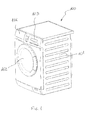
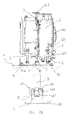
Fig. 1 is a perspective view of a laundry washing machine according to the present invention; -
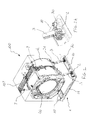
Figs. 2 and 2A are a front perspective view of the laundry washing machine of the present invention and a respective detail thereof in which a casing has been depicted in transparency in order to show internal components of the laundry washing machine; -
Figs. 3 and 3A are a rear perspective view of the laundry washing machine ofFig. 2 and a respective detail thereof; -
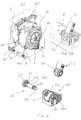
Fig. 4 is an exploded rear perspective view of a damper element and of a damper fixing assembly of the laundry washing machine according to the present invention; -
Fig. 5 is a perspective view of the damper element, of the damper fixing assembly and of a flat plate of a supporting structure of the laundry washing machine according to the present invention; -
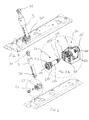
Figs. 6 and 6A are an exploded front perspective view of the damper element, of the damper fixing assembly and of the flat plate ofFig. 5 , and a respective detail thereof; -
Figs. 7 and 7A are a side view of the laundry washing machine of the present invention and a respective detail thereof, in which the casing has been removed in order to show internal components; and -
Figs 8A and8B are perspective views of a pin and of a shoulder of the damper fixing assembly in a partially screwed and in a fully screwed position, respectively. - With reference initially to
Fig. 1 , a laundry washing machine according to the present invention is globally indicated with thereference number 100. - It should be noted that in the context of the present invention with the expression "washing machine" is referred both to a "standard" washing machine, adapted only for washing and rinsing the laundry, and to a washer-drier, which is adapted for washing, rinsing, and also for drying the laundry.
- The
laundry washing machine 100 comprises anouter casing 101, preferably but not necessarily parallelepiped-shaped, and atreatment chamber 4 housing adrum 40, both shown inFig. 2 , for receiving the laundry and in general the clothes and garments to be washed and/or dried. Preferably, thedrum 40 has the shape of a hollow cylinder and it is rotatably fixed to the casing, so that it can rotate around an axis thereof. According to the present embodiment, the rotation axis of thedrum 40 is substantially horizontal but it should be appreciated that, as an alternative, the drum can be positioned in thecasing 101 in such a position that its rotation axis is vertical or tilted. - Always with reference to
Fig. 1 , an aperture is defined in the casing, facing the treatment chamber and thus allowing accessing to the drum for loading and unloading the laundry in the machine. Thewashing laundry machine 100 further comprises adoor assembly 102, preferably pivotally supported on thecasing 101 and displaceable between a closed position, shown inFig. 1 and in which the aperture is closed or preferably sealed and an open position in which access to the drum is allowed. - According to the present embodiment, the aperture is defined in a front face of the
casing 101, in which are also located acontrol panel 103 of themachine 100 and adrawer 104 suitable for containing detergents and other additives in washing machines or for collecting water in dryers. - In other words, the
device 100 according to present embodiment is a front-load device. Nevertheless it will be appreciated that the present invention could also apply to different types of washing laundry machines, such as top-loading ones. - With reference now to
Fig. 2 , thewashing machine 100 according to the present invention further comprises a supporting structure 1 of thetreatment chamber 4. - According to a preferred embodiment, the supporting structure 1 comprises
feet 12, preferably adjustable and shown inFig. 7 , onto which thewashing machine 100 rests on the floor F. - Preferably, the supporting structure 1 comprises a pair of flat shaped
plates 10, onto which the feet are fixed. According to the present embodiment,plates 10 are parallel each other and also parallel to the axis of rotation of the drum. In order to increase the sturdiness of the supporting structure 1, theplates 10 are advantageously connected by means of at least onetransverse beam 11. - Preferably, the casing is fixed, e.g. by means of screws, clincing or other similar connections, to the
plates 10 and/or to thebeam 11. - According to a preferred embodiment, the
washing machine 100 comprisesdamper elements 3, connecting thetreatment chamber 4 to theplates 10 or, more in general, to the supporting structure 1. In the present advantageous embodiment, thewashing machine 100 comprises threedamper elements 3, two fixed to oneplate 10 and one fixed to theother plate 10. Accordingly, thetreatment chamber 4 is advantageously supported in correspondence of three different points, thus suitably dampening both lateral and vertical vibrations and oscillations. - Preferably, the
damper elements 3 are tilted with respect to a vertical axis, in order to improve the stability of thetreatment chamber 4. - According to the present embodiment, the
damper elements 3 comprise a cylinder inside which a stem can slide. A damper media is housed in the cylinder, dampening the movement of the stem. Opposed connecting ends 30, 31 of the stem and of the cylinder, respectively, are provided with a seat allowing the connection of the damper element. Preferably, the seat is defined by a through hole, optionally provided with a bushing. - With reference also to
Fig. 2A , thewashing machine 100 further comprisesdamper fixing assemblies 2 for fixing, preferably in a rotatable manner, thedamper element 3 on the supporting structure 1. In the present embodiment, eachdamper element 3 is fixed by means of a respective fixing assembly, but it will be appreciated that the present invention could also apply for fixing a single damper element of a washing machine. - As shown in
Fig. 3 ,washing machine 100 further comprises a motor assembly 6 for rotating thedrum 40. Preferably, the motor assembly is mounted at the bottom of thelaundry treating chamber 4 and transmits a rotation movement to thedrum 4 by means of abelt 60. - Also according to a preferred embodiment, the
washing machine 100 further comprises anupper beam 107, associated to thecasing 101, for supporting of the treatingchamber 4 by means of resilient elements, e.g. two springs. - With reference now to
Fig. 4 , thedamper fixing assembly 2 comprises a pair ofshoulders 22, 22', preferably formed by arms of anU-shaped bracket 20 connected or connectable to theplates 10. Preferably, thebracket 20 is fixed to theplate 10 both by a shape coupling defined by a connection element, not shown in the Figures, which is/can be engaged on a respective seat in the plates, and by screws, fixing thebracket 20 after it has been positioned. - The
damper fixing assembly 2 further comprises apin 21 which is/can be engaged in the bracket as will be described in greater detail in the following. - As shown in
Figs. 4 and6A , theshoulders 22, 22' are each provided with a respective threadedhole 220, 220'. The axes of the threadedholes 220, 220' are aligned and respective threadedportions 210, 210' of thepin 21 are/can be engaged therein. - Preferably, the threaded
portions 210, 210' are separated therebetween by a smoothcylindrical portion 212. The distance between the threaded portions is substantially the same of the distance between theshoulders 22 and 22'. - In this manner, when the
pin 21 is inserted in both threadedholes 220 and 220', each threadedportions 210 and 210' is engaged in a respective hole. - The smooth
cylindrical portion 212 is/can be associated to the connectingend 30 of thedamper element 3. In the present embodiment, the smoothcylindrical portion 212 is/can be coupled to the circular seat defined in theconnection end 30, with the bushing interposed therebetween. - It should be noted that in the context of the present invention, with the term smooth will be intended that the
portion 212 is not provided with any thread and its surface has a sufficiently low friction coefficient such that it does not to prevent or excessively impede the rotation of thedamper element 3 on thepin 21. - It should be understood that in order to engage each other, the female thread of threaded
holes 220 and 220' should have the same diameter and the same pitch of the male thread of the respective threadedportion 210, 210' of thepin 21. Since different diameters of a thread can be considered, in the context of the present invention the term diameter of the thread will be used with the meaning of nominal diameter. - According to a preferred embodiment, the diameter D of the threaded
hole 220 of oneshoulder 22 and of a respective first threadedportion 210 of thepin 21 is larger than the diameter d of the threaded hole 220' of the other shoulder 22' and of a respective second threaded portion 210' of thepin 21. - Preferably, the diameter of the smooth portion is larger than the diameter d of the small threaded portion 210' and smaller than the diameter D of the large threaded
portion 210. This allows an easy assembly of the connectingend 30 on the pin, as well as an easy engagement of thepin 21 on thebracket 20. - Always according to a preferred embodiment, the
pin 21 further comprises a taperedtip 211 axially extending from the small threaded portion 210'. - Preferably, the
pin 21 comprises an operatinghead 213, e.g. a hexagonal head, which can be therefore operated with a suitable tool. - Therefore, according to the present embodiment, the
pin 21 comprises in sequence the operatinghead 213, the first threadedportion 210, the smoothcylindrical portion 212, the second threaded portion 210' and the taperedtip 211. - Accordingly, the
damper element 3 is/can be fixed to the supporting structure 1 by positioning the connectingend 30 between theshoulders 22 and 22', then inserting thepin 21 in theholes 220 and 220' and finally screwing thepin 21. - According to a preferred embodiment, the
damper fixing assembly 2 further comprises a blockingdevice pin 21 in an unscrewing direction. - With reference in particular to
Figs. 8A and8B , the blocking device comprises a first and asecond projection pin 21 and on thefirst shoulder 22. Preferably, the first andsecond projection pin 21 is fully screwed on thebracket 22. - In order to engage each other, the
first projection 51 advantageously comprises aslanted surface 510 facing arespective surface 520 of theother projection 52. Theslanted surface 510 defines aleading edge 511 and a trailingedge 512 of the projection. It should be anyhow appreciated that bothprojections surface leading edge 511 and the trailingedge 512 are defined such that, when thepin 21 is screwed on theholes 220, 220', theleading edge 511 is more distant from the other projection than the trailingedge 512. When the pin is screwed, the first andsecond projections - According to a preferred embodiment, the first and/or
second projection slanted surface 510 engages with therespective surface 520 of theother projection 52 during rotation of saidpin 51, theprojections pin 21 on the bracket, with thefirst projection 51 passing over thesecond projection 52, as shown inFig, 8B . - Preferably, the slanted surface engages with the respective surface of the other projection only when the pin is almost fully screwed on the bracket. It should be noted that according to the present embodiment, an
abutment surface 214 is defined. When thepin 21 is screwed on thebracket 20, theabutment surface 214 approaches thefirst shoulder 22, until it abuts theshoulder 22 in a fully screwed position. Within the context of the present invention, the almost fully screwed position is reached by thepin 21 when only a portion of rotation, i.e. less than 360 degrees, is required for theabutment surface 214 to abut against the shoulder. - According to a preferred embodiment, the
first projection 51 projects in a radial direction from the operatingkey 213, and the trailingedge 512 projects from theabutment surface 214 towards theshoulder 220. Theshoulder 22 further comprises acollar 224 onto which theabutment surface 214 abuts when thepin 21 is fully screwed, and thesecond projection 52 projects in a radial direction from thecollar 224. - Preferably, the threaded
holes 220, 220' and the respective threadedportions 210, 210' have single-start thread forms, so that thepin 21 can be screwed on thebracket 20 only starting from a predetermined angular position. In this manner the position of theprojections pin 21. - It has thus been shown that the present invention allows all the set objects to be achieved. In particular, the provision of threaded holes in which respective threaded portions of the pin allows a simple and precise assembly of the damper elements.
wherein the shoulders comprise respective threaded holes in which respective threaded portions of the pin are/can be engaged.
Claims (13)
- A washing machine (100) comprising:• a treatment chamber (4) comprising a drum (40) for receiving a load to be washed;• a supporting structure (1) of said treatment chamber (4);• at least one damper element (3) connecting said treatment chamber (4) to said supporting structure (1);• a damper fixing assembly (2) for rotatably fixing said at least one damper element (3) on said supporting structure (1), said damper fixing assembly (2) comprising a pair of shoulders (22, 22') and a pin (21);
wherein said at least one damper element (3) comprises a first connecting end (30) which is/can be rotatably engaged with said pin (21) and which is/can be positioned between said shoulders (22, 22'),
characterized in that
said shoulders (22, 22') comprise respective threaded holes (220, 220') in which respective threaded portions (210, 210') of said pin (21) are/can be engaged. - The washing machine (100) according to claim 1, wherein the diameter (D) of the threaded hole (220) of one shoulder (22) and of a respective first threaded portion (210) of said pin (21) is larger than the diameter (d) of the threaded hole (220') of the other shoulder (22') and of a respective second threaded portion (210') of said pin (21).
- The washing machine (100) according to claim 1 or 2, wherein said pin (21) comprises a tapered tip (211) axially extending from one of said threaded portions (210, 210').
- The washing machine (100) according to any of the preceding claims, wherein said pin (21) comprises a smooth cylindrical portion (212) between said respective threaded portions (210, 210').
- The washing machine (100) according to claim 4, wherein a seat (31) is defined in said first connecting end (30), said seat (31) being rotatably coupled with said smooth cylindrical portion (212).
- The washing machine (100) according to any of the preceding claims, wherein said shoulders (22, 22') are formed by arms of an U-shaped bracket (20) connected or connectable to said supporting structure (1).
- The washing machine (100) according to any of the preceding claims, wherein said damper fixing assembly (2) comprises a blocking device (51, 52) for preventing rotation of said pin (21) in an unscrewing direction.
- The washing machine (100) according to claim 7, wherein said blocking device comprises a first and a second projection (51, 52) respectively on said pin (21) and on one shoulder (22) of said pair of shoulders (22, 22'), said first and second projection (51, \52) engaging each other when said pin (21) is fully screwed on said bracket (22).
- The washing machine (100) according to claim 8, wherein said first and/or said second projection (51, 52) comprise a slanted surface (510, 520) facing a respective surface of the other projection and defining a leading edge (511) and a trailing edge (512) of the projection, said leading edge (511) being more distant from the other projection than said trailing edge (512).
- The washing machine (100) according to claim 8 or 9, wherein said pin (21) comprises an operating head (213) in which an abutment surface (214) is defined, said abutment surface (214) abutting on one shoulder (22) of said pair of shoulders when said pin (21) is fully screwed on said bracket (20), said first projection (51) projecting in a radial direction from said operating head (213), said trailing edge (512) projecting from said abutment surface (214) towards said shoulder (22).
- The washing machine (100) according to claim 10, wherein said shoulder (22) comprises a collar (224) onto which said abutment surface (214) abuts, said second projection (52) projecting in radial direction from said collar (224).
- The washing machine (100) according to any of claims 8 to 11, wherein said first and/or second projection (51, 52) are at least partially elastically deformable and wherein the slanted surface (510, 520) of one projection (51) engages the other projection (52) during rotation of said pin (21) such that said projections (51, 52) are forced apart upon the engagement of said slanted surface (510, 520) with the other projection (52).
- The washing machine (100) according to any of the preceding claims, wherein said threaded holes (220, 220') and said respective threaded portions (210, 210') have single-start thread forms.
Priority Applications (2)
| Application Number | Priority Date | Filing Date | Title |
|---|---|---|---|
| EP13184843.4A EP2848723B1 (en) | 2013-09-17 | 2013-09-17 | Washing laundry machine with damper elements |
| PCT/EP2014/066851 WO2015039801A1 (en) | 2013-09-17 | 2014-08-05 | Washing laundry machine with damper elements |
Applications Claiming Priority (1)
| Application Number | Priority Date | Filing Date | Title |
|---|---|---|---|
| EP13184843.4A EP2848723B1 (en) | 2013-09-17 | 2013-09-17 | Washing laundry machine with damper elements |
Publications (2)
| Publication Number | Publication Date |
|---|---|
| EP2848723A1 true EP2848723A1 (en) | 2015-03-18 |
| EP2848723B1 EP2848723B1 (en) | 2021-02-24 |
Family
ID=49212646
Family Applications (1)
| Application Number | Title | Priority Date | Filing Date |
|---|---|---|---|
| EP13184843.4A Not-in-force EP2848723B1 (en) | 2013-09-17 | 2013-09-17 | Washing laundry machine with damper elements |
Country Status (2)
| Country | Link |
|---|---|
| EP (1) | EP2848723B1 (en) |
| WO (1) | WO2015039801A1 (en) |
Cited By (3)
| Publication number | Priority date | Publication date | Assignee | Title |
|---|---|---|---|---|
| EP3115495A1 (en) * | 2015-07-10 | 2017-01-11 | Vestel Beyaz Esya Sanayi Ve Ticaret A.S. | Washing and/or drying device with a damper |
| CN110387677A (en) * | 2018-04-19 | 2019-10-29 | 青岛海尔智能技术研发有限公司 | Tumbling-box washing machine and its damping device |
| WO2020238466A1 (en) * | 2019-05-27 | 2020-12-03 | 海信(山东)冰箱有限公司 | Washing machine and fastener applied to washing machine |
Families Citing this family (1)
| Publication number | Priority date | Publication date | Assignee | Title |
|---|---|---|---|---|
| US11441594B2 (en) | 2019-08-22 | 2022-09-13 | Haier Us Appliance Solutions, Inc. | Fastening assembly for a thin-walled part of an appliance |
Citations (12)
| Publication number | Priority date | Publication date | Assignee | Title |
|---|---|---|---|---|
| US4472075A (en) * | 1981-07-16 | 1984-09-18 | Tourolle Et Fils | Pivotable connecting device |
| US5114260A (en) * | 1991-05-13 | 1992-05-19 | Hart Judy L | Clevis and screw pin type shackle with pin lock |
| JP2001170389A (en) * | 1999-12-20 | 2001-06-26 | Sharp Corp | Drum type washing machine |
| US20040244436A1 (en) * | 2003-03-26 | 2004-12-09 | Park Gwan Ryong | Damper mounting structure for washing machine |
| WO2005085510A1 (en) | 2004-03-03 | 2005-09-15 | Suspa Holding Gmbh | Coupling device for coupling an oscillation damper to a washing unit and/or a machine frame of a washing machine |
| EP1703010A1 (en) * | 2005-03-17 | 2006-09-20 | MIGLIO EMILIO S.r.l. | Device for coupling the tub supporting arms in linen washing machines and the like |
| US20070044519A1 (en) * | 2005-08-26 | 2007-03-01 | Sung-Ryong Kim | Washing machine having damper-supporter |
| EP1760183A2 (en) | 2005-09-01 | 2007-03-07 | Samsung Electronics Co., Ltd. | Washing and/or Drying Machine Having a Damper Connecting Structure Including a Reinforcing Portion |
| EP1892326A2 (en) | 2006-08-21 | 2008-02-27 | Miele & Cie. KG | Plastic tub for a washing machine with a connection for a vibration damper |
| US7373793B2 (en) | 2004-02-25 | 2008-05-20 | Lg Electronics Inc. | Damper assembly and washing machine using the same |
| EP1980661A1 (en) | 2007-04-12 | 2008-10-15 | Vestel Beyaz Esya Sanayi Ve Ticaret A.S. | Shock absorber sleeve and pin |
| EP2348149A1 (en) | 2010-01-25 | 2011-07-27 | Bonferraro S.p.A. | Pin for mounting the drum dampers of a washing machine |
-
2013
- 2013-09-17 EP EP13184843.4A patent/EP2848723B1/en not_active Not-in-force
-
2014
- 2014-08-05 WO PCT/EP2014/066851 patent/WO2015039801A1/en not_active Ceased
Patent Citations (12)
| Publication number | Priority date | Publication date | Assignee | Title |
|---|---|---|---|---|
| US4472075A (en) * | 1981-07-16 | 1984-09-18 | Tourolle Et Fils | Pivotable connecting device |
| US5114260A (en) * | 1991-05-13 | 1992-05-19 | Hart Judy L | Clevis and screw pin type shackle with pin lock |
| JP2001170389A (en) * | 1999-12-20 | 2001-06-26 | Sharp Corp | Drum type washing machine |
| US20040244436A1 (en) * | 2003-03-26 | 2004-12-09 | Park Gwan Ryong | Damper mounting structure for washing machine |
| US7373793B2 (en) | 2004-02-25 | 2008-05-20 | Lg Electronics Inc. | Damper assembly and washing machine using the same |
| WO2005085510A1 (en) | 2004-03-03 | 2005-09-15 | Suspa Holding Gmbh | Coupling device for coupling an oscillation damper to a washing unit and/or a machine frame of a washing machine |
| EP1703010A1 (en) * | 2005-03-17 | 2006-09-20 | MIGLIO EMILIO S.r.l. | Device for coupling the tub supporting arms in linen washing machines and the like |
| US20070044519A1 (en) * | 2005-08-26 | 2007-03-01 | Sung-Ryong Kim | Washing machine having damper-supporter |
| EP1760183A2 (en) | 2005-09-01 | 2007-03-07 | Samsung Electronics Co., Ltd. | Washing and/or Drying Machine Having a Damper Connecting Structure Including a Reinforcing Portion |
| EP1892326A2 (en) | 2006-08-21 | 2008-02-27 | Miele & Cie. KG | Plastic tub for a washing machine with a connection for a vibration damper |
| EP1980661A1 (en) | 2007-04-12 | 2008-10-15 | Vestel Beyaz Esya Sanayi Ve Ticaret A.S. | Shock absorber sleeve and pin |
| EP2348149A1 (en) | 2010-01-25 | 2011-07-27 | Bonferraro S.p.A. | Pin for mounting the drum dampers of a washing machine |
Cited By (5)
| Publication number | Priority date | Publication date | Assignee | Title |
|---|---|---|---|---|
| EP3115495A1 (en) * | 2015-07-10 | 2017-01-11 | Vestel Beyaz Esya Sanayi Ve Ticaret A.S. | Washing and/or drying device with a damper |
| CN110387677A (en) * | 2018-04-19 | 2019-10-29 | 青岛海尔智能技术研发有限公司 | Tumbling-box washing machine and its damping device |
| CN110387677B (en) * | 2018-04-19 | 2023-04-18 | 青岛海尔智能技术研发有限公司 | Drum type washing machine and damping device thereof |
| WO2020238466A1 (en) * | 2019-05-27 | 2020-12-03 | 海信(山东)冰箱有限公司 | Washing machine and fastener applied to washing machine |
| CN113677845A (en) * | 2019-05-27 | 2021-11-19 | 海信(山东)冰箱有限公司 | Washing machine and fastener applied to the washing machine |
Also Published As
| Publication number | Publication date |
|---|---|
| WO2015039801A1 (en) | 2015-03-26 |
| EP2848723B1 (en) | 2021-02-24 |
Similar Documents
| Publication | Publication Date | Title |
|---|---|---|
| EP2848723B1 (en) | Washing laundry machine with damper elements | |
| EP2886706B1 (en) | Device for fixing a wall-mounted drum type washing machine | |
| US9340916B2 (en) | Laundry treating appliance suspension system | |
| US10023988B2 (en) | Washing machine | |
| KR102218909B1 (en) | Laundry Treating Apparatus | |
| US10988884B2 (en) | Clothes treating apparatus | |
| CN219808129U (en) | Clothes treating apparatus | |
| CN106661804A (en) | Laundry treatment apparatus | |
| GB2512495A (en) | Laundry Treatment apparatus | |
| CN107354696A (en) | Cloth drying utensil with heat pump and corresponding drive device | |
| US20040244436A1 (en) | Damper mounting structure for washing machine | |
| KR102331601B1 (en) | Supporting Unit and Laundry Treating Apparatus having the same | |
| WO2015078519A1 (en) | Capacitor holder | |
| EP2896733B1 (en) | Clothes treating apparatus and method for manufacturing a clothes treating apparatus | |
| RU2675472C1 (en) | Vibration cushioning device, electric household device and method for manufacturing this device | |
| CN207267942U (en) | Device for clothing processing and the draining pump component for device for clothing processing | |
| US20070204659A1 (en) | Damper Pin In Drum Type Washing Machine | |
| WO2017080703A1 (en) | Domestic appliance for treating laundry items, comprising an imbalance compensation device secured by radially elastic clips | |
| KR101962132B1 (en) | Washing Machine | |
| WO2016142120A1 (en) | Domestic appliance for the care of laundry items, comprising an imbalance correcting device fastened by brackets | |
| CN214005156U (en) | A bumper shock absorber and washing machine for washing machine | |
| CN218142866U (en) | Clothes care appliance | |
| KR20210030111A (en) | Laundry treating apparatus | |
| CN110924075A (en) | A fixed subassembly and washing equipment for washing equipment | |
| KR20150074492A (en) | Damper for washing machine and washing machine thereof |
Legal Events
| Date | Code | Title | Description |
|---|---|---|---|
| PUAI | Public reference made under article 153(3) epc to a published international application that has entered the european phase |
Free format text: ORIGINAL CODE: 0009012 |
|
| 17P | Request for examination filed |
Effective date: 20130917 |
|
| AK | Designated contracting states |
Kind code of ref document: A1 Designated state(s): AL AT BE BG CH CY CZ DE DK EE ES FI FR GB GR HR HU IE IS IT LI LT LU LV MC MK MT NL NO PL PT RO RS SE SI SK SM TR |
|
| AX | Request for extension of the european patent |
Extension state: BA ME |
|
| R17P | Request for examination filed (corrected) |
Effective date: 20150918 |
|
| RBV | Designated contracting states (corrected) |
Designated state(s): AL AT BE BG CH CY CZ DE DK EE ES FI FR GB GR HR HU IE IS IT LI LT LU LV MC MK MT NL NO PL PT RO RS SE SI SK SM TR |
|
| GRAP | Despatch of communication of intention to grant a patent |
Free format text: ORIGINAL CODE: EPIDOSNIGR1 |
|
| STAA | Information on the status of an ep patent application or granted ep patent |
Free format text: STATUS: GRANT OF PATENT IS INTENDED |
|
| INTG | Intention to grant announced |
Effective date: 20201008 |
|
| RAP1 | Party data changed (applicant data changed or rights of an application transferred) |
Owner name: ELECTROLUX APPLIANCES AKTIEBOLAG |
|
| GRAS | Grant fee paid |
Free format text: ORIGINAL CODE: EPIDOSNIGR3 |
|
| GRAA | (expected) grant |
Free format text: ORIGINAL CODE: 0009210 |
|
| STAA | Information on the status of an ep patent application or granted ep patent |
Free format text: STATUS: THE PATENT HAS BEEN GRANTED |
|
| AK | Designated contracting states |
Kind code of ref document: B1 Designated state(s): AL AT BE BG CH CY CZ DE DK EE ES FI FR GB GR HR HU IE IS IT LI LT LU LV MC MK MT NL NO PL PT RO RS SE SI SK SM TR |
|
| REG | Reference to a national code |
Ref country code: GB Ref legal event code: FG4D |
|
| REG | Reference to a national code |
Ref country code: CH Ref legal event code: EP |
|
| REG | Reference to a national code |
Ref country code: AT Ref legal event code: REF Ref document number: 1364564 Country of ref document: AT Kind code of ref document: T Effective date: 20210315 |
|
| REG | Reference to a national code |
Ref country code: IE Ref legal event code: FG4D |
|
| REG | Reference to a national code |
Ref country code: DE Ref legal event code: R096 Ref document number: 602013075823 Country of ref document: DE |
|
| REG | Reference to a national code |
Ref country code: LT Ref legal event code: MG9D |
|
| REG | Reference to a national code |
Ref country code: NL Ref legal event code: MP Effective date: 20210224 |
|
| PG25 | Lapsed in a contracting state [announced via postgrant information from national office to epo] |
Ref country code: LT Free format text: LAPSE BECAUSE OF FAILURE TO SUBMIT A TRANSLATION OF THE DESCRIPTION OR TO PAY THE FEE WITHIN THE PRESCRIBED TIME-LIMIT Effective date: 20210224 Ref country code: PT Free format text: LAPSE BECAUSE OF FAILURE TO SUBMIT A TRANSLATION OF THE DESCRIPTION OR TO PAY THE FEE WITHIN THE PRESCRIBED TIME-LIMIT Effective date: 20210624 Ref country code: HR Free format text: LAPSE BECAUSE OF FAILURE TO SUBMIT A TRANSLATION OF THE DESCRIPTION OR TO PAY THE FEE WITHIN THE PRESCRIBED TIME-LIMIT Effective date: 20210224 Ref country code: FI Free format text: LAPSE BECAUSE OF FAILURE TO SUBMIT A TRANSLATION OF THE DESCRIPTION OR TO PAY THE FEE WITHIN THE PRESCRIBED TIME-LIMIT Effective date: 20210224 Ref country code: GR Free format text: LAPSE BECAUSE OF FAILURE TO SUBMIT A TRANSLATION OF THE DESCRIPTION OR TO PAY THE FEE WITHIN THE PRESCRIBED TIME-LIMIT Effective date: 20210525 Ref country code: NO Free format text: LAPSE BECAUSE OF FAILURE TO SUBMIT A TRANSLATION OF THE DESCRIPTION OR TO PAY THE FEE WITHIN THE PRESCRIBED TIME-LIMIT Effective date: 20210524 Ref country code: BG Free format text: LAPSE BECAUSE OF FAILURE TO SUBMIT A TRANSLATION OF THE DESCRIPTION OR TO PAY THE FEE WITHIN THE PRESCRIBED TIME-LIMIT Effective date: 20210524 |
|
| REG | Reference to a national code |
Ref country code: AT Ref legal event code: MK05 Ref document number: 1364564 Country of ref document: AT Kind code of ref document: T Effective date: 20210224 |
|
| PG25 | Lapsed in a contracting state [announced via postgrant information from national office to epo] |
Ref country code: PL Free format text: LAPSE BECAUSE OF FAILURE TO SUBMIT A TRANSLATION OF THE DESCRIPTION OR TO PAY THE FEE WITHIN THE PRESCRIBED TIME-LIMIT Effective date: 20210224 Ref country code: LV Free format text: LAPSE BECAUSE OF FAILURE TO SUBMIT A TRANSLATION OF THE DESCRIPTION OR TO PAY THE FEE WITHIN THE PRESCRIBED TIME-LIMIT Effective date: 20210224 Ref country code: NL Free format text: LAPSE BECAUSE OF FAILURE TO SUBMIT A TRANSLATION OF THE DESCRIPTION OR TO PAY THE FEE WITHIN THE PRESCRIBED TIME-LIMIT Effective date: 20210224 Ref country code: RS Free format text: LAPSE BECAUSE OF FAILURE TO SUBMIT A TRANSLATION OF THE DESCRIPTION OR TO PAY THE FEE WITHIN THE PRESCRIBED TIME-LIMIT Effective date: 20210224 Ref country code: SE Free format text: LAPSE BECAUSE OF FAILURE TO SUBMIT A TRANSLATION OF THE DESCRIPTION OR TO PAY THE FEE WITHIN THE PRESCRIBED TIME-LIMIT Effective date: 20210224 |
|
| PG25 | Lapsed in a contracting state [announced via postgrant information from national office to epo] |
Ref country code: IS Free format text: LAPSE BECAUSE OF FAILURE TO SUBMIT A TRANSLATION OF THE DESCRIPTION OR TO PAY THE FEE WITHIN THE PRESCRIBED TIME-LIMIT Effective date: 20210624 |
|
| PG25 | Lapsed in a contracting state [announced via postgrant information from national office to epo] |
Ref country code: AT Free format text: LAPSE BECAUSE OF FAILURE TO SUBMIT A TRANSLATION OF THE DESCRIPTION OR TO PAY THE FEE WITHIN THE PRESCRIBED TIME-LIMIT Effective date: 20210224 Ref country code: SM Free format text: LAPSE BECAUSE OF FAILURE TO SUBMIT A TRANSLATION OF THE DESCRIPTION OR TO PAY THE FEE WITHIN THE PRESCRIBED TIME-LIMIT Effective date: 20210224 Ref country code: CZ Free format text: LAPSE BECAUSE OF FAILURE TO SUBMIT A TRANSLATION OF THE DESCRIPTION OR TO PAY THE FEE WITHIN THE PRESCRIBED TIME-LIMIT Effective date: 20210224 Ref country code: EE Free format text: LAPSE BECAUSE OF FAILURE TO SUBMIT A TRANSLATION OF THE DESCRIPTION OR TO PAY THE FEE WITHIN THE PRESCRIBED TIME-LIMIT Effective date: 20210224 |
|
| REG | Reference to a national code |
Ref country code: DE Ref legal event code: R097 Ref document number: 602013075823 Country of ref document: DE |
|
| PG25 | Lapsed in a contracting state [announced via postgrant information from national office to epo] |
Ref country code: RO Free format text: LAPSE BECAUSE OF FAILURE TO SUBMIT A TRANSLATION OF THE DESCRIPTION OR TO PAY THE FEE WITHIN THE PRESCRIBED TIME-LIMIT Effective date: 20210224 Ref country code: DK Free format text: LAPSE BECAUSE OF FAILURE TO SUBMIT A TRANSLATION OF THE DESCRIPTION OR TO PAY THE FEE WITHIN THE PRESCRIBED TIME-LIMIT Effective date: 20210224 Ref country code: ES Free format text: LAPSE BECAUSE OF FAILURE TO SUBMIT A TRANSLATION OF THE DESCRIPTION OR TO PAY THE FEE WITHIN THE PRESCRIBED TIME-LIMIT Effective date: 20210224 Ref country code: SK Free format text: LAPSE BECAUSE OF FAILURE TO SUBMIT A TRANSLATION OF THE DESCRIPTION OR TO PAY THE FEE WITHIN THE PRESCRIBED TIME-LIMIT Effective date: 20210224 |
|
| PLBE | No opposition filed within time limit |
Free format text: ORIGINAL CODE: 0009261 |
|
| STAA | Information on the status of an ep patent application or granted ep patent |
Free format text: STATUS: NO OPPOSITION FILED WITHIN TIME LIMIT |
|
| PG25 | Lapsed in a contracting state [announced via postgrant information from national office to epo] |
Ref country code: AL Free format text: LAPSE BECAUSE OF FAILURE TO SUBMIT A TRANSLATION OF THE DESCRIPTION OR TO PAY THE FEE WITHIN THE PRESCRIBED TIME-LIMIT Effective date: 20210224 |
|
| 26N | No opposition filed |
Effective date: 20211125 |
|
| PG25 | Lapsed in a contracting state [announced via postgrant information from national office to epo] |
Ref country code: SI Free format text: LAPSE BECAUSE OF FAILURE TO SUBMIT A TRANSLATION OF THE DESCRIPTION OR TO PAY THE FEE WITHIN THE PRESCRIBED TIME-LIMIT Effective date: 20210224 |
|
| REG | Reference to a national code |
Ref country code: CH Ref legal event code: PL |
|
| REG | Reference to a national code |
Ref country code: BE Ref legal event code: MM Effective date: 20210930 |
|
| GBPC | Gb: european patent ceased through non-payment of renewal fee |
Effective date: 20210917 |
|
| PG25 | Lapsed in a contracting state [announced via postgrant information from national office to epo] |
Ref country code: IS Free format text: LAPSE BECAUSE OF FAILURE TO SUBMIT A TRANSLATION OF THE DESCRIPTION OR TO PAY THE FEE WITHIN THE PRESCRIBED TIME-LIMIT Effective date: 20210624 Ref country code: MC Free format text: LAPSE BECAUSE OF FAILURE TO SUBMIT A TRANSLATION OF THE DESCRIPTION OR TO PAY THE FEE WITHIN THE PRESCRIBED TIME-LIMIT Effective date: 20210224 |
|
| PG25 | Lapsed in a contracting state [announced via postgrant information from national office to epo] |
Ref country code: LU Free format text: LAPSE BECAUSE OF NON-PAYMENT OF DUE FEES Effective date: 20210917 Ref country code: IE Free format text: LAPSE BECAUSE OF NON-PAYMENT OF DUE FEES Effective date: 20210917 Ref country code: GB Free format text: LAPSE BECAUSE OF NON-PAYMENT OF DUE FEES Effective date: 20210917 Ref country code: FR Free format text: LAPSE BECAUSE OF NON-PAYMENT OF DUE FEES Effective date: 20210930 Ref country code: BE Free format text: LAPSE BECAUSE OF NON-PAYMENT OF DUE FEES Effective date: 20210930 |
|
| PG25 | Lapsed in a contracting state [announced via postgrant information from national office to epo] |
Ref country code: LI Free format text: LAPSE BECAUSE OF NON-PAYMENT OF DUE FEES Effective date: 20210930 Ref country code: CH Free format text: LAPSE BECAUSE OF NON-PAYMENT OF DUE FEES Effective date: 20210930 |
|
| PG25 | Lapsed in a contracting state [announced via postgrant information from national office to epo] |
Ref country code: HU Free format text: LAPSE BECAUSE OF FAILURE TO SUBMIT A TRANSLATION OF THE DESCRIPTION OR TO PAY THE FEE WITHIN THE PRESCRIBED TIME-LIMIT; INVALID AB INITIO Effective date: 20130917 |
|
| PG25 | Lapsed in a contracting state [announced via postgrant information from national office to epo] |
Ref country code: CY Free format text: LAPSE BECAUSE OF FAILURE TO SUBMIT A TRANSLATION OF THE DESCRIPTION OR TO PAY THE FEE WITHIN THE PRESCRIBED TIME-LIMIT Effective date: 20210224 |
|
| P01 | Opt-out of the competence of the unified patent court (upc) registered |
Effective date: 20230625 |
|
| PGFP | Annual fee paid to national office [announced via postgrant information from national office to epo] |
Ref country code: IT Payment date: 20230920 Year of fee payment: 11 |
|
| PGFP | Annual fee paid to national office [announced via postgrant information from national office to epo] |
Ref country code: DE Payment date: 20230928 Year of fee payment: 11 |
|
| PG25 | Lapsed in a contracting state [announced via postgrant information from national office to epo] |
Ref country code: MK Free format text: LAPSE BECAUSE OF FAILURE TO SUBMIT A TRANSLATION OF THE DESCRIPTION OR TO PAY THE FEE WITHIN THE PRESCRIBED TIME-LIMIT Effective date: 20210224 |
|
| PG25 | Lapsed in a contracting state [announced via postgrant information from national office to epo] |
Ref country code: TR Free format text: LAPSE BECAUSE OF FAILURE TO SUBMIT A TRANSLATION OF THE DESCRIPTION OR TO PAY THE FEE WITHIN THE PRESCRIBED TIME-LIMIT Effective date: 20210224 |
|
| PG25 | Lapsed in a contracting state [announced via postgrant information from national office to epo] |
Ref country code: MT Free format text: LAPSE BECAUSE OF FAILURE TO SUBMIT A TRANSLATION OF THE DESCRIPTION OR TO PAY THE FEE WITHIN THE PRESCRIBED TIME-LIMIT Effective date: 20210224 |
|
| REG | Reference to a national code |
Ref country code: DE Ref legal event code: R119 Ref document number: 602013075823 Country of ref document: DE |
|
| PG25 | Lapsed in a contracting state [announced via postgrant information from national office to epo] |
Ref country code: DE Free format text: LAPSE BECAUSE OF NON-PAYMENT OF DUE FEES Effective date: 20250401 |
|
| PG25 | Lapsed in a contracting state [announced via postgrant information from national office to epo] |
Ref country code: IT Free format text: LAPSE BECAUSE OF NON-PAYMENT OF DUE FEES Effective date: 20240917 |