EP2848452A2 - Traction converter system - Google Patents
Traction converter system Download PDFInfo
- Publication number
- EP2848452A2 EP2848452A2 EP14177472.9A EP14177472A EP2848452A2 EP 2848452 A2 EP2848452 A2 EP 2848452A2 EP 14177472 A EP14177472 A EP 14177472A EP 2848452 A2 EP2848452 A2 EP 2848452A2
- Authority
- EP
- European Patent Office
- Prior art keywords
- power
- transformer
- charging resistor
- power converter
- converter
- Prior art date
- Legal status (The legal status is an assumption and is not a legal conclusion. Google has not performed a legal analysis and makes no representation as to the accuracy of the status listed.)
- Withdrawn
Links
- 230000001172 regenerating effect Effects 0.000 claims abstract description 29
- 238000005096 rolling process Methods 0.000 claims abstract description 26
- 239000003990 capacitor Substances 0.000 claims abstract description 22
- 238000004804 winding Methods 0.000 claims description 12
- 238000000926 separation method Methods 0.000 claims description 4
- 230000008929 regeneration Effects 0.000 description 3
- 238000011069 regeneration method Methods 0.000 description 3
- 230000000694 effects Effects 0.000 description 2
- 238000000034 method Methods 0.000 description 2
- 230000009467 reduction Effects 0.000 description 2
- 230000001629 suppression Effects 0.000 description 2
- 230000001133 acceleration Effects 0.000 description 1
- 230000009471 action Effects 0.000 description 1
- 230000008859 change Effects 0.000 description 1
- 230000006866 deterioration Effects 0.000 description 1
- 238000005516 engineering process Methods 0.000 description 1
- 230000004907 flux Effects 0.000 description 1
- 230000007274 generation of a signal involved in cell-cell signaling Effects 0.000 description 1
- 230000010354 integration Effects 0.000 description 1
- 230000005415 magnetization Effects 0.000 description 1
- 230000002265 prevention Effects 0.000 description 1
Images



Classifications
-
- B—PERFORMING OPERATIONS; TRANSPORTING
- B60—VEHICLES IN GENERAL
- B60L—PROPULSION OF ELECTRICALLY-PROPELLED VEHICLES; SUPPLYING ELECTRIC POWER FOR AUXILIARY EQUIPMENT OF ELECTRICALLY-PROPELLED VEHICLES; ELECTRODYNAMIC BRAKE SYSTEMS FOR VEHICLES IN GENERAL; MAGNETIC SUSPENSION OR LEVITATION FOR VEHICLES; MONITORING OPERATING VARIABLES OF ELECTRICALLY-PROPELLED VEHICLES; ELECTRIC SAFETY DEVICES FOR ELECTRICALLY-PROPELLED VEHICLES
- B60L50/00—Electric propulsion with power supplied within the vehicle
- B60L50/50—Electric propulsion with power supplied within the vehicle using propulsion power supplied by batteries or fuel cells
-
- B—PERFORMING OPERATIONS; TRANSPORTING
- B60—VEHICLES IN GENERAL
- B60L—PROPULSION OF ELECTRICALLY-PROPELLED VEHICLES; SUPPLYING ELECTRIC POWER FOR AUXILIARY EQUIPMENT OF ELECTRICALLY-PROPELLED VEHICLES; ELECTRODYNAMIC BRAKE SYSTEMS FOR VEHICLES IN GENERAL; MAGNETIC SUSPENSION OR LEVITATION FOR VEHICLES; MONITORING OPERATING VARIABLES OF ELECTRICALLY-PROPELLED VEHICLES; ELECTRIC SAFETY DEVICES FOR ELECTRICALLY-PROPELLED VEHICLES
- B60L9/00—Electric propulsion with power supply external to the vehicle
- B60L9/16—Electric propulsion with power supply external to the vehicle using AC induction motors
- B60L9/18—Electric propulsion with power supply external to the vehicle using AC induction motors fed from DC supply lines
- B60L9/22—Electric propulsion with power supply external to the vehicle using AC induction motors fed from DC supply lines polyphase motors
-
- B—PERFORMING OPERATIONS; TRANSPORTING
- B60—VEHICLES IN GENERAL
- B60L—PROPULSION OF ELECTRICALLY-PROPELLED VEHICLES; SUPPLYING ELECTRIC POWER FOR AUXILIARY EQUIPMENT OF ELECTRICALLY-PROPELLED VEHICLES; ELECTRODYNAMIC BRAKE SYSTEMS FOR VEHICLES IN GENERAL; MAGNETIC SUSPENSION OR LEVITATION FOR VEHICLES; MONITORING OPERATING VARIABLES OF ELECTRICALLY-PROPELLED VEHICLES; ELECTRIC SAFETY DEVICES FOR ELECTRICALLY-PROPELLED VEHICLES
- B60L7/00—Electrodynamic brake systems for vehicles in general
- B60L7/10—Dynamic electric regenerative braking
- B60L7/14—Dynamic electric regenerative braking for vehicles propelled by AC motors
-
- B—PERFORMING OPERATIONS; TRANSPORTING
- B60—VEHICLES IN GENERAL
- B60L—PROPULSION OF ELECTRICALLY-PROPELLED VEHICLES; SUPPLYING ELECTRIC POWER FOR AUXILIARY EQUIPMENT OF ELECTRICALLY-PROPELLED VEHICLES; ELECTRODYNAMIC BRAKE SYSTEMS FOR VEHICLES IN GENERAL; MAGNETIC SUSPENSION OR LEVITATION FOR VEHICLES; MONITORING OPERATING VARIABLES OF ELECTRICALLY-PROPELLED VEHICLES; ELECTRIC SAFETY DEVICES FOR ELECTRICALLY-PROPELLED VEHICLES
- B60L7/00—Electrodynamic brake systems for vehicles in general
- B60L7/22—Dynamic electric resistor braking, combined with dynamic electric regenerative braking
-
- B—PERFORMING OPERATIONS; TRANSPORTING
- B60—VEHICLES IN GENERAL
- B60L—PROPULSION OF ELECTRICALLY-PROPELLED VEHICLES; SUPPLYING ELECTRIC POWER FOR AUXILIARY EQUIPMENT OF ELECTRICALLY-PROPELLED VEHICLES; ELECTRODYNAMIC BRAKE SYSTEMS FOR VEHICLES IN GENERAL; MAGNETIC SUSPENSION OR LEVITATION FOR VEHICLES; MONITORING OPERATING VARIABLES OF ELECTRICALLY-PROPELLED VEHICLES; ELECTRIC SAFETY DEVICES FOR ELECTRICALLY-PROPELLED VEHICLES
- B60L9/00—Electric propulsion with power supply external to the vehicle
- B60L9/16—Electric propulsion with power supply external to the vehicle using AC induction motors
- B60L9/18—Electric propulsion with power supply external to the vehicle using AC induction motors fed from DC supply lines
-
- B—PERFORMING OPERATIONS; TRANSPORTING
- B60—VEHICLES IN GENERAL
- B60L—PROPULSION OF ELECTRICALLY-PROPELLED VEHICLES; SUPPLYING ELECTRIC POWER FOR AUXILIARY EQUIPMENT OF ELECTRICALLY-PROPELLED VEHICLES; ELECTRODYNAMIC BRAKE SYSTEMS FOR VEHICLES IN GENERAL; MAGNETIC SUSPENSION OR LEVITATION FOR VEHICLES; MONITORING OPERATING VARIABLES OF ELECTRICALLY-PROPELLED VEHICLES; ELECTRIC SAFETY DEVICES FOR ELECTRICALLY-PROPELLED VEHICLES
- B60L9/00—Electric propulsion with power supply external to the vehicle
- B60L9/16—Electric propulsion with power supply external to the vehicle using AC induction motors
- B60L9/24—Electric propulsion with power supply external to the vehicle using AC induction motors fed from AC supply lines
-
- B—PERFORMING OPERATIONS; TRANSPORTING
- B60—VEHICLES IN GENERAL
- B60L—PROPULSION OF ELECTRICALLY-PROPELLED VEHICLES; SUPPLYING ELECTRIC POWER FOR AUXILIARY EQUIPMENT OF ELECTRICALLY-PROPELLED VEHICLES; ELECTRODYNAMIC BRAKE SYSTEMS FOR VEHICLES IN GENERAL; MAGNETIC SUSPENSION OR LEVITATION FOR VEHICLES; MONITORING OPERATING VARIABLES OF ELECTRICALLY-PROPELLED VEHICLES; ELECTRIC SAFETY DEVICES FOR ELECTRICALLY-PROPELLED VEHICLES
- B60L9/00—Electric propulsion with power supply external to the vehicle
- B60L9/16—Electric propulsion with power supply external to the vehicle using AC induction motors
- B60L9/24—Electric propulsion with power supply external to the vehicle using AC induction motors fed from AC supply lines
- B60L9/28—Electric propulsion with power supply external to the vehicle using AC induction motors fed from AC supply lines polyphase motors
-
- Y—GENERAL TAGGING OF NEW TECHNOLOGICAL DEVELOPMENTS; GENERAL TAGGING OF CROSS-SECTIONAL TECHNOLOGIES SPANNING OVER SEVERAL SECTIONS OF THE IPC; TECHNICAL SUBJECTS COVERED BY FORMER USPC CROSS-REFERENCE ART COLLECTIONS [XRACs] AND DIGESTS
- Y02—TECHNOLOGIES OR APPLICATIONS FOR MITIGATION OR ADAPTATION AGAINST CLIMATE CHANGE
- Y02T—CLIMATE CHANGE MITIGATION TECHNOLOGIES RELATED TO TRANSPORTATION
- Y02T10/00—Road transport of goods or passengers
- Y02T10/60—Other road transportation technologies with climate change mitigation effect
- Y02T10/70—Energy storage systems for electromobility, e.g. batteries
Definitions
- the present invention relates to a traction converter system and a method of driving a traction converter system for AC rolling stock or AC-DC rolling stock.
- An electric rolling stock traveling in an AC electrified section has a traction converter control system including a first power converter that converts AC power input from a power wire via a transformer into DC power, and a second power converter that converts DC power into three-phase AC power.
- a traction converter control system including a first power converter that converts AC power input from a power wire via a transformer into DC power, and a second power converter that converts DC power into three-phase AC power.
- the rolling stock is decelerated using an air brake.
- the brake shoe of the air brake is worn according to the frequency of use, and there is a problem that, when the frequency of use of the air brake is higher, the brake shoe is getting worn and the replacement cycle of the brake shoe is shorter.
- a brake chopper system that obtains a braking force by consuming power generated in the motor with a resistor called a brake resistor when it is impossible to use the regenerative brake has been designed and put into practical use.
- the frequency of use of the air brake may be reduced.
- Patent Document 1 JP-A-2004-312939 .
- Patent Document 1 an existing device is applied to the chopper device and the reactor and the brake resistor are separately necessary, and the downsizing effect on the device is smaller.
- the invention has been achieved in view of the problems in related art, and an object of the invention is to propose a brake chopper system with reduced additional devices.
- a traction converter system includes a transformer that transforms AC power input from a collector collecting AC power, a first power converter that converts the AC power transformed in the transformer into DC power, a second power converter that converts the DC power into three-phase AC power, a filter capacitor provided between the first and the second power converters, and a charging resistor provided between the first power converter and the transformer and limiting charge current flowing from the transformer into the filter capacitor, wherein the first power converter supplies regenerative power generated in a three-phase AC motor at braking of a rolling stock to the charging resistor and consumes the regenerative power with the charging resistor.
- a reactor and a brake resistor necessary for the brake chopper device in related art is used in common with other devices, and thereby, the number of devices may be reduced and the number of parts of the traction converter system may be reduced.
- reduction in size and weight of the system may be realized and a risk of failure may be reduced and reliability may be improved by the reduction of the number of parts.
- Fig. 1 shows a first example in a traction converter system of the invention.
- a first power converter 1 converts AC power supplied from a pantograph for AC power wire 2 via a switch 3 and a transformer 4 into DC power and supplies the power to a second power converter 9.
- the first power converter 1 includes switching elements 1a to 1d.
- each of the switching elements 1a to 1d includes a transistor such as an IGBT and a diode connected in reverse parallel to the transistor.
- 1a and 1b, 1c and 1d are respectively series-connected, and a series circuit of 1a and 1b and a series circuit of 1c and 1d are parallel-connected.
- an intermediate point between the switching elements 1a and 1b is connected to one side of a secondary-side winding of the transformer and an intermediate point between the switching elements 1c and 1d is connected to the other side of the secondary-side winding of the transformer.
- the switch 3 may be a vacuum circuit breaker that can break a current or an electromagnetic contactor that opens and closes an electric circuit by an action of an electromagnet, or has a configuration in which the vacuum circuit breaker and the electromagnetic contactor are series-connected.
- a brake reactor 14 is connected in parallel to the transformer 4 between the charging resistor 5 and the electromagnetic contactor 6 and the electromagnetic contactor 12, and is opened by an electromagnetic contactor 13 when the brake reactor 14 is not used.
- the electromagnetic contactor 12 is connected between the transformer 4 and the charging resistor 5 and the electromagnetic contactor 6, however, it is only necessary that the electromagnetic contactor 12 is connected between the transformer 4 and the brake reactor 14. That is, the electromagnetic contactor 12 may be provided between the transformer 4 and the switching elements 1c and 1d or provided on both ends of the transformer. Further, the electromagnetic contactor 13 that opens the brake reactor 14 may be provided on either side of the brake reactor 14, or on both ends, not on one end of the brake reactor 14.
- a part between the first power converter 1 and the second power converter 9 is referred to as "DC stage", and a filter circuit 7 that absorbs rectification ripple twice the power wire voltage frequency and a filter capacitor 8 are provided on the DC stage.
- the filter circuit 7 is not necessarily provided.
- the second power converter 9 converts DC supplied from the first power converter 1 into three-phase AC power to drive a three-phase motor 10.
- a controller 11 outputs signals Pc and pi for controlling the first power converter 1 and the second power converter 9.
- the controller 11 closes only the switch 12. Concurrently, a current flows to the filter capacitor 8 via the charging resistor 5, and, even when the filter capacitor 8 is not charged, flow of overcurrent is prevented. Then, when the voltage of the filter capacitor 8 exceeds a predetermined value, the switch 6 is closed.
- the voltage when the switch 6 is closed may be a fixed value or changed according to a secondary voltage of the transformer.
- the controller 11 determines that the regenerative power should not be returned to the power wire and switches the first power converter 1 to a mode of operating the power converter 1 as a brake chopper (hereinafter, referred to as "brake chopper mode").
- brake chopper mode first, the first power converter 1 and the second power converter 9 are stopped, and the electromagnetic contactor 12 and the electromagnetic contactor 6 are opened.
- the switch 3 It is not necessarily to open the switch 3, however, it is desirable to open the switch when the pantograph 2 is in contact with the power wire.
- the switch 3 has a configuration in which the vacuum circuit breaker and the electromagnetic contactor are series connected, only the electromagnetic contactor is opened for suppression of the number of operations of the vacuum circuit breaker. After opening of these devices is confirmed, the electromagnetic contactor 13 is closed and the brake reactor 14 is connected to the main circuit.
- the controller 11 allows the second power converter 9 to perform regenerative operation again, and allows the first power converter 1 to operate as a brake chopper that controls the current flowing in the charging resistor 5 so that the voltage of the filter capacitor 8 may be constant.
- a path 1 through the switching elements 1a and 1d as shown in Fig. 3 and a path 2 through the switching elements 1b and 1c as shown in Fig. 4 are considered, and the current may flow in either path.
- the path may be changed if the number of times when the first power converter 1 is operated as the chopper device reaches a predetermined number, the path may be changed if the time when the first power converter is operated as the chopper device reaches a predetermined time, or the time integrated value of the current flowing in one path may be calculated and the path may be changed if the time integrated value (i.e., total amount of current) reaches a predetermined value.
- the power converter may be temporarily stopped so that the switching element at the high-voltage side and the switching element at the low-voltage side of the same phase may not simultaneously turned on, and then, the current path may be changed.
- Figs. 3 and 4 it is necessary to constantly turn off the switching element not in the path in which the current flows for prevention of short circuit between the high-voltage side and the low-voltage side.
- the control signal of the switching element at the high-voltage side e.g., 1a
- the control signal of the switching element at the low-voltage side e.g., 1b
- Fig. 5 shows an example of a logic for realization of control signal generation of the brake chopper in the configurations in Figs. 3 and 4 .
- control signals of the switching elements 1a to 1d are digital signals with on-command of "1" and off-commend of "0", and additionally, flags indicating the current paths and enabling signals 1aSW to 1dSW with "1" indicating “enable” and "0” indicating “disable” are used.
- flags indicating the current paths and enabling signals 1aSW to 1dSW with "1" indicating “enable” and "0” indicating “disable” are used.
- the case where, in the path 1, the switching element 1a at the high-voltage side is switched, the switching element 1d is in the conduction state, and the switching element 1b and the switching element 1c are constantly off is considered.
- the enabling signal 1dSW for switching of 1d is "0"
- the output is constantly "1”, i.e., on-command
- the control signal is output without change. That is, switching of the switching element 1a is controlled based on the control signal for controlling the conduction ratio of the switching element 1a so that the voltage of the filter capacitor 8 may be constant.
- the conduction ratio of the switching element when the whole break force of the rolling stock is consumed in the charging resistor, it is necessary to control the conduction ratio of the switching element so that the voltage of the filter capacitor 8 may be constant, however, when the break force of the rolling stock is shared by the charging resistor and the air break, the conduction ratio of the switching element is determined according to the amount of breaking borne by the charging resistor.
- the element to be switched may be either element at the high-voltage side or the low-voltage side, and the element to be switched may be alternately changed between the high-voltage side and the low-voltage side at each time when the first power converter 1 is operated as the chopper like the current path.
- the path may be changed if the number of times when the first power converter 1 is operated as the chopper device reaches a predetermined number, the path may be changed if the time when the first power converter is operated as the chopper device reaches a predetermined time, the time integrated value of the current flowing in one path may be calculated and the element to be switched may be changed between the high-voltage side and the low-voltage side if the time integrated value reaches a predetermined value.
- the operation of the first power converter 1 and the second power converter 9 is once stopped and the electromagnetic contactor 13 is opened. Then, after closing and opening of the respective devices that close the switch 3, the electromagnetic contactor 6, and the electromagnetic contactor 12 are confirmed, the normal regenerative operation of returning power from the second power converter 9 to the power wire via the first power converter 1 and the transformer 4 is performed.
- the brake chopper is formed using the first power converter 1, the charging resistor 5, and the brake reactor 14, and thereby, the charging resistor 5 may be used as a resistor that suppresses an excessive charge current to the filter capacitor 8 and a resistor that consumes the regenerative power. Therefore, a smaller brake chopper system than the brake chopper system in related art may be realized.
- driving of one three-phase motor is shown, however, a configuration in which a plurality of three-phase motors are driven may be employed.
- connection of one first power converter to the transformer 4 is shown, however, a configuration in which a plurality of first power converters are connected may be employed and, in this case, it is only necessary that the parallel circuit of the charging resistor and the electromagnetic contactor and the brake reactor are connected with respect to each first power converter.
- Fig. 6 shows a second example in the traction converter system of the invention.
- the example is different from the example 1 in that no brake reactor 14 is connected.
- the brake chopper system is formed using a secondary-side winding of the transformer 4 as a break reactor in place of the brake reactor 14 and the brake reactor 14 and the electromagnetic contactors 12 and 13 are removed from the circuit in Fig. 1 , however, the electromagnetic contactor 12 may be provided.
- the controller 11 determines that the regenerative power should not be returned to the power wire and switches to the brake chopper mode. Then, first, the first power converter 1 and the second power converter 9 are stopped, and the switch 3 and the electromagnetic contactor 6 are opened.
- the switch 3 has a configuration in which the vacuum circuit breaker and the electromagnetic contactor are series-connected, only the electromagnetic contactor is opened for suppression of the number of operations of the vacuum circuit breaker.
- the second power converter 9 is allowed to perform regenerative operation again, and the first power converter 1 is allowed to be operated as a brake chopper that controls the current flowing in the charging resistor 5 so that the voltage of the filter capacitor 8 may be constant.
- the operation as the brake chopper is the same as the operation in the example 1.
- the operation of the first power converter 1 and the second power converter 9 is once stopped and the switch 3 and the electromagnetic contactor 6 are closed. Then, the normal regenerative operation of returning power from the second power converter 9 to the power wire via the first power converter 1 and the transformer 4 is performed. Note that, in the case where the secondary-side winding of the transformer 4 is used as the brake reactor, magnetization may occur in the transformer after use, and accordingly, the first power converter 1 may be controlled to eliminate the magnetic flux accumulated in the transformer 4 before the switch 3 and the electromagnetic contactor 6 are closed.
- the current flowing in the transformer 4 may be time integrated, and the current may flow in the transformer 4 so that the integration result may be zero before the switch 3 and the electromagnetic contactor 6 are closed. That is, the integrated values of the currents flowing in the transformer 4 in the opposite directions may be made nearly equal.
- the brake chopper is formed using the first power converter 1, the transformer 4, and the charging resistor 5, and thereby, the brake reactor 14 and the electromagnetic contactor 13 may be omitted from the example 1 and the brake chopper system may be further downsized.
- driving of one three-phase motor is shown, however, a configuration in which a plurality of three-phase motors are driven may be employed.
- connection of one first power converter to the transformer is shown, however, a configuration in which a plurality of first power converters are connected may be employed and, in this case, it is only necessary that the charging resistor and the electromagnetic contactor are parallel-connected with respect to each first power converter.
- Fig. 7 shows a third example in the traction converter system of the invention.
- the example is different from the example 1 in that an AC-DC rolling stock can travel even in a DC power line section.
- a pantograph for DC power wire 15 is in contact with the power wire when traveling in the DC power wire section, and DC power is supplied from the pantograph 15 to a DC stage part via a high-speed circuit breaker 16 and a filter reactor 19.
- An interrupter 18 and a charging resistor for DC 17 are connected between the high-speed circuit breaker 16 and the filter reactor 19.
- the output side of the filter reactor 19 is connected to an intermediate part of the filter circuit 7, and this is for the reactor forming the filter circuit 7 to have the same function as the filter reactor 19.
- the output side of the filter reactor may be directly connected to the high-voltage side of the DC stage.
- the switch 3 and the electromagnetic contactors 6 and 12 are opened and the electromagnetic contactor 13 is closed.
- the high-speed circuit breaker 16 and the interrupter 18 are opened.
- the pantograph for DC power wire 15 may be used in common with the pantograph for AC power wire 2.
- a switch 20 is provided between the pantograph 2, and the switch 3 and the high-speed circuit breaker 16 as shown in Fig. 8 , and the current path is changed between the AC section and the DC section.
- the switch 20 in the case of traveling in the DC power wire section, the switch 20 is connected to the high-speed circuit breaker 16 side, the switch 3 and the electromagnetic contactors 6 and 12 are opened, and the electromagnetic contactor 13 is closed.
- the switch 20 is connected to the switch 3 side, and the high-speed circuit breaker 16 and the interrupter 18 are opened.
- the switch 20 is connected to the switch 3 side
- the main circuit configuration is the same as that of the example 1, and the same operation as that of the example 1 is performed.
- an operation for preventing flow of overcurrent from the power wire into the filter capacitor 8 using the charging resistor 5 is explained.
- the controller 11 closes only the switch 12. Concurrently, a current flows to the filter capacitor 8 via the charging resistor 5, and, even when the filter capacitor 8 is not charged, flow of overcurrent is prevented. Then, when the voltage of the filter capacitor 8 exceeds a predetermined value, the switch 6 is closed.
- the voltage when the switch 6 is closed may be a fixed value or changed according to a secondary voltage of the transformer.
- the first power converter 1 may constantly operate as a brake chopper device, and the operation as the brake chopper is the same as that of the example 1. Further, even when one of separation of the pantograph, passage in the dead section, and traveling on a line for which returning of power to the power wire is not allowed is sensed during regeneration of the rolling stock, it is not necessary to open the high-speed circuit breaker 16 and the interrupter 18 because they have no effect on the chopper operation of the first power converter 1 without being opened. Note that, in the configuration like the example, the controller 11 may execute light load regenerative operation when rise of the power wire voltage to a predetermined value or more is sensed, and it is preferable to open the high-speed circuit breaker 16 and the interrupter 18.
- the secondary-side winding of the transformer 4 may be used as the brake reactor like the example 2, and Fig. 9 shows a circuit configuration in this case.
- the configuration is the same as that of Fig. 7 except the absence of the electromagnetic contactor 13 and the brake reactor 14.
- a brake chopper mode may be provided, and the second power converter 9 may be allowed to start braking operation and the first power converter 1 may be allowed to be operated as a brake chopper device in the section.
- the brake chopper is formed using the first power converter 1, the transformer 4, and the charging resistor 5, and thereby, addition of devices may be reduced and the brake chopper system may be downsized.
- driving of one three-phase motor is shown, however, a configuration in which a plurality of three-phase motors are driven may be employed.
- connection of one first power converter to the transformer is shown, however, a configuration in which a plurality of first power converters are connected may be employed and, in this case, it is only necessary that the charging resistor and the electromagnetic contactor are parallel-connected with respect to each first power converter.
Landscapes
- Engineering & Computer Science (AREA)
- Power Engineering (AREA)
- Transportation (AREA)
- Mechanical Engineering (AREA)
- Life Sciences & Earth Sciences (AREA)
- Sustainable Development (AREA)
- Sustainable Energy (AREA)
- Electric Propulsion And Braking For Vehicles (AREA)
- Inverter Devices (AREA)
- Power Conversion In General (AREA)
- Rectifiers (AREA)
Abstract
Description
- The present invention relates to a traction converter system and a method of driving a traction converter system for AC rolling stock or AC-DC rolling stock.
- An electric rolling stock traveling in an AC electrified section has a traction converter control system including a first power converter that converts AC power input from a power wire via a transformer into DC power, and a second power converter that converts DC power into three-phase AC power. When the rolling stock travels in the DC section, power from the power wire is input to a DC output unit between the first power converter and the second power converter.
- In the electric rolling stock, at acceleration, three-phase AC power is supplied from the power wire to a motor via the first power converter and the second power converter in the AC section, three-phase AC power is supplied from the power wire to the motor via the second power converter in the DC section, and thereby, the motor is driven. In the electric rolling stock, at deceleration, the three-phase AC power generated in the motor is returned to the power wire via the second power converter, the first power converter, and the transformer in the AC section, the power is returned to the power wire via the second power converter in the DC section, and thereby, a regenerative brake that reuses the generated power is used.
- However, in the case where it is impossible to return power to the power wire when a pantograph is separated from the power wire or when the rolling stock passes through a dead section, where the rolling stock travels on a line for which returning of power to the power wire is not allowed, or where the voltage of the power wire rises to a predetermined value or more, so that it is impossible return power to the power wire, the rolling stock is decelerated using an air brake. In the air brake, the brake shoe of the air brake is worn according to the frequency of use, and there is a problem that, when the frequency of use of the air brake is higher, the brake shoe is getting worn and the replacement cycle of the brake shoe is shorter. Accordingly, a brake chopper system that obtains a braking force by consuming power generated in the motor with a resistor called a brake resistor when it is impossible to use the regenerative brake has been designed and put into practical use. By the brake chopper system, the frequency of use of the air brake may be reduced.
- On the other hand, for the brake chopper system, it is necessary to provide a chopper device, a resistor, and a reactor separately from the first power converter and the second power converter, and there is a problem in mounting that the traction converter system becomes larger.
- In contrast, a method of reducing the devices forming the brake chopper system by using the first power converter as the chopper device is disclosed in Patent Document 1 (
JP-A-2004-312939 - However, in
Patent Document 1, an existing device is applied to the chopper device and the reactor and the brake resistor are separately necessary, and the downsizing effect on the device is smaller. - The invention has been achieved in view of the problems in related art, and an object of the invention is to propose a brake chopper system with reduced additional devices.
- In order to solve the problems, a traction converter system includes a transformer that transforms AC power input from a collector collecting AC power, a first power converter that converts the AC power transformed in the transformer into DC power, a second power converter that converts the DC power into three-phase AC power, a filter capacitor provided between the first and the second power converters, and a charging resistor provided between the first power converter and the transformer and limiting charge current flowing from the transformer into the filter capacitor, wherein the first power converter supplies regenerative power generated in a three-phase AC motor at braking of a rolling stock to the charging resistor and consumes the regenerative power with the charging resistor.
- According to the invention, a reactor and a brake resistor necessary for the brake chopper device in related art is used in common with other devices, and thereby, the number of devices may be reduced and the number of parts of the traction converter system may be reduced. Thus, there are advantages that reduction in size and weight of the system may be realized and a risk of failure may be reduced and reliability may be improved by the reduction of the number of parts.
-
-
Fig. 1 shows a system configuration in example 1. -
Fig. 2 shows another system configuration in example 1. -
Fig. 3 shows acurrent path 1 in example 1, example 2, example 3. -
Fig. 4 shows acurrent path 2 in example 1, example 2, example 3. -
Fig. 5 shows a control logic in example 1, example 2, example 3. -
Fig. 6 shows a system configuration in example 2. -
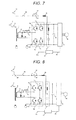
Fig. 7 shows a system configuration in example 3. -
Fig. 8 shows another system configuration in example 3. -
Fig. 9 shows another system configuration in example 3. - As below, a plurality of specific examples will be explained using the drawings.
-
Fig. 1 shows a first example in a traction converter system of the invention. - First, configurations of devices will be explained. A
first power converter 1 converts AC power supplied from a pantograph forAC power wire 2 via a switch 3 and a transformer 4 into DC power and supplies the power to a second power converter 9. Here, thefirst power converter 1 includes switchingelements 1a to 1d. Specifically, each of theswitching elements 1a to 1d includes a transistor such as an IGBT and a diode connected in reverse parallel to the transistor. 1a and 1b, 1c and 1d are respectively series-connected, and a series circuit of 1a and 1b and a series circuit of 1c and 1d are parallel-connected. Further, an intermediate point between theswitching elements switching elements - The switch 3 may be a vacuum circuit breaker that can break a current or an electromagnetic contactor that opens and closes an electric circuit by an action of an electromagnet, or has a configuration in which the vacuum circuit breaker and the electromagnetic contactor are series-connected. A circuit in which a
charging resistor 5 and anelectromagnetic contactor 6 are parallel-connected and anelectromagnetic contactor 12 are series-connected between thefirst power converter 1 and the transformer 4. Abrake reactor 14 is connected in parallel to the transformer 4 between thecharging resistor 5 and theelectromagnetic contactor 6 and theelectromagnetic contactor 12, and is opened by anelectromagnetic contactor 13 when thebrake reactor 14 is not used. - Here, in
Fig. 1 , theelectromagnetic contactor 12 is connected between the transformer 4 and thecharging resistor 5 and theelectromagnetic contactor 6, however, it is only necessary that theelectromagnetic contactor 12 is connected between the transformer 4 and thebrake reactor 14. That is, theelectromagnetic contactor 12 may be provided between the transformer 4 and theswitching elements electromagnetic contactor 13 that opens thebrake reactor 14 may be provided on either side of thebrake reactor 14, or on both ends, not on one end of thebrake reactor 14. - A part between the
first power converter 1 and the second power converter 9 is referred to as "DC stage", and afilter circuit 7 that absorbs rectification ripple twice the power wire voltage frequency and afilter capacitor 8 are provided on the DC stage. Thefilter circuit 7 is not necessarily provided. The second power converter 9 converts DC supplied from thefirst power converter 1 into three-phase AC power to drive a three-phase motor 10. Acontroller 11 outputs signals Pc and pi for controlling thefirst power converter 1 and the second power converter 9. - Next, a specific operation of the traction converter system will be explained.
- First, an operation for preventing flow of overcurrent from the power wire into the
filter capacitor 8 using thecharging resistor 5 is explained. When confirming that the switch 3 has been closed, thecontroller 11 closes only theswitch 12. Concurrently, a current flows to thefilter capacitor 8 via thecharging resistor 5, and, even when thefilter capacitor 8 is not charged, flow of overcurrent is prevented. Then, when the voltage of thefilter capacitor 8 exceeds a predetermined value, theswitch 6 is closed. The voltage when theswitch 6 is closed may be a fixed value or changed according to a secondary voltage of the transformer. - Then, an operation when regenerative power is consumed in the
charging resistor 5 is explained. When sensing one of separation of the pantograph, passage in the dead section, traveling on a line for which returning of power to the power wire is not allowed, and rise of the power wire voltage to a predetermined value or more during regeneration of the rolling stock, thecontroller 11 determines that the regenerative power should not be returned to the power wire and switches thefirst power converter 1 to a mode of operating thepower converter 1 as a brake chopper (hereinafter, referred to as "brake chopper mode"). In the brake chopper mode, first, thefirst power converter 1 and the second power converter 9 are stopped, and theelectromagnetic contactor 12 and theelectromagnetic contactor 6 are opened. It is not necessarily to open the switch 3, however, it is desirable to open the switch when thepantograph 2 is in contact with the power wire. In this regard, when the switch 3 has a configuration in which the vacuum circuit breaker and the electromagnetic contactor are series connected, only the electromagnetic contactor is opened for suppression of the number of operations of the vacuum circuit breaker. After opening of these devices is confirmed, theelectromagnetic contactor 13 is closed and thebrake reactor 14 is connected to the main circuit. - When the
electromagnetic contactor 13 is closed, thecontroller 11 allows the second power converter 9 to perform regenerative operation again, and allows thefirst power converter 1 to operate as a brake chopper that controls the current flowing in thecharging resistor 5 so that the voltage of thefilter capacitor 8 may be constant. - When the
first power converter 1 is operated as the brake chopper, as a path in which a current flows, apath 1 through theswitching elements Fig. 3 and apath 2 through theswitching elements Fig. 4 are considered, and the current may flow in either path. - Here, according to the technology of
Patent Document 1, only a part of the first power converter is applied to the chopper device, and there is a problem that only a part of the switching elements of the first power converter is frequently used and deteriorated and reliability as the whole first power converter is lower. Accordingly, for example, in order to homogenize the degree of deterioration of theswitching elements 1a to 1d forming thefirst power converter 1, thepath 1 and thepath 2 may be alternately exchanged at each time when thefirst power converter 1 is operated as the chopper. In addition, the path may be changed if the number of times when thefirst power converter 1 is operated as the chopper device reaches a predetermined number, the path may be changed if the time when the first power converter is operated as the chopper device reaches a predetermined time, or the time integrated value of the current flowing in one path may be calculated and the path may be changed if the time integrated value (i.e., total amount of current) reaches a predetermined value. When the current path is changed, the power converter may be temporarily stopped so that the switching element at the high-voltage side and the switching element at the low-voltage side of the same phase may not simultaneously turned on, and then, the current path may be changed. - As described above, when the
first power converter 1 is operated in the same manner as the brake chopper in related art, it is necessary to mount a control system that operates on the break chopper in addition to a control system as the typical power converter on thecontroller 11 of thefirst power converter 1. These controls may be changed at the start of the brake chopper mode. - Further, in
Figs. 3 and 4 , it is necessary to constantly turn off the switching element not in the path in which the current flows for prevention of short circuit between the high-voltage side and the low-voltage side. However, depending on the device, only the control signal of the switching element at the high-voltage side (e.g., 1a) may be calculated and the control signal of the switching element at the low-voltage side (e.g., 1b) may be created by inversion of the control signal at the high-voltage side within thecontroller 11. In this case, it is impossible to generate a control signal in the brake chopper mode of operating only the switching element at the high-voltage side or the low-voltage side. Accordingly, processing of determining the element to be switched for each path in which the current flows and constantly turning on or constantly turning off the other elements according to the flow path is added.Fig. 5 shows an example of a logic for realization of control signal generation of the brake chopper in the configurations inFigs. 3 and 4 . - In the logic of
Fig. 5 , the control signals of theswitching elements 1a to 1d are digital signals with on-command of "1" and off-commend of "0", and additionally, flags indicating the current paths and enabling signals 1aSW to 1dSW with "1" indicating "enable" and "0" indicating "disable" are used. For example, the case where, in thepath 1, the switchingelement 1a at the high-voltage side is switched, theswitching element 1d is in the conduction state, and theswitching element 1b and the switchingelement 1c are constantly off is considered. First, the current flows in thepath 1 and the flag of thepath 2 is not on and the output of the control signals of theswitching elements element 1a, the control signal is output without change. That is, switching of theswitching element 1a is controlled based on the control signal for controlling the conduction ratio of theswitching element 1a so that the voltage of thefilter capacitor 8 may be constant. Here, when the whole break force of the rolling stock is consumed in the charging resistor, it is necessary to control the conduction ratio of the switching element so that the voltage of thefilter capacitor 8 may be constant, however, when the break force of the rolling stock is shared by the charging resistor and the air break, the conduction ratio of the switching element is determined according to the amount of breaking borne by the charging resistor. - Note that the element to be switched may be either element at the high-voltage side or the low-voltage side, and the element to be switched may be alternately changed between the high-voltage side and the low-voltage side at each time when the
first power converter 1 is operated as the chopper like the current path. In addition, the path may be changed if the number of times when thefirst power converter 1 is operated as the chopper device reaches a predetermined number, the path may be changed if the time when the first power converter is operated as the chopper device reaches a predetermined time, the time integrated value of the current flowing in one path may be calculated and the element to be switched may be changed between the high-voltage side and the low-voltage side if the time integrated value reaches a predetermined value. - If it becomes possible to return the power to the power wire while the
first power converter 1 is operated as the chopper device, first, the operation of thefirst power converter 1 and the second power converter 9 is once stopped and theelectromagnetic contactor 13 is opened. Then, after closing and opening of the respective devices that close the switch 3, theelectromagnetic contactor 6, and theelectromagnetic contactor 12 are confirmed, the normal regenerative operation of returning power from the second power converter 9 to the power wire via thefirst power converter 1 and the transformer 4 is performed. - As described above, the brake chopper is formed using the
first power converter 1, the chargingresistor 5, and thebrake reactor 14, and thereby, the chargingresistor 5 may be used as a resistor that suppresses an excessive charge current to thefilter capacitor 8 and a resistor that consumes the regenerative power. Therefore, a smaller brake chopper system than the brake chopper system in related art may be realized. InFig. 1 of the example 1, driving of one three-phase motor is shown, however, a configuration in which a plurality of three-phase motors are driven may be employed. Further, connection of one first power converter to the transformer 4 is shown, however, a configuration in which a plurality of first power converters are connected may be employed and, in this case, it is only necessary that the parallel circuit of the charging resistor and the electromagnetic contactor and the brake reactor are connected with respect to each first power converter. -
Fig. 6 shows a second example in the traction converter system of the invention. The example is different from the example 1 in that nobrake reactor 14 is connected. - First, configurations of devices will be explained. The configurations are nearly the same as those in
Fig. 1 , and only the differences will be explained. In the example 2, the brake chopper system is formed using a secondary-side winding of the transformer 4 as a break reactor in place of thebrake reactor 14 and thebrake reactor 14 and theelectromagnetic contactors Fig. 1 , however, theelectromagnetic contactor 12 may be provided. - Next, a specific operation of the traction converter system will be explained. When sensing one of separation of the pantograph, passage in the dead section, traveling on a line for which returning of power to the power wire is not allowed, and rise of the power wire voltage to a predetermined value or more during regeneration of the rolling stock, the
controller 11 determines that the regenerative power should not be returned to the power wire and switches to the brake chopper mode. Then, first, thefirst power converter 1 and the second power converter 9 are stopped, and the switch 3 and theelectromagnetic contactor 6 are opened. In this regard, when the switch 3 has a configuration in which the vacuum circuit breaker and the electromagnetic contactor are series-connected, only the electromagnetic contactor is opened for suppression of the number of operations of the vacuum circuit breaker. After opening of these devices is confirmed, the second power converter 9 is allowed to perform regenerative operation again, and thefirst power converter 1 is allowed to be operated as a brake chopper that controls the current flowing in the chargingresistor 5 so that the voltage of thefilter capacitor 8 may be constant. The operation as the brake chopper is the same as the operation in the example 1. - If it becomes possible to return the power to the power wire while the
first power converter 1 is operated as the chopper device, first, the operation of thefirst power converter 1 and the second power converter 9 is once stopped and the switch 3 and theelectromagnetic contactor 6 are closed. Then, the normal regenerative operation of returning power from the second power converter 9 to the power wire via thefirst power converter 1 and the transformer 4 is performed. Note that, in the case where the secondary-side winding of the transformer 4 is used as the brake reactor, magnetization may occur in the transformer after use, and accordingly, thefirst power converter 1 may be controlled to eliminate the magnetic flux accumulated in the transformer 4 before the switch 3 and theelectromagnetic contactor 6 are closed. For example, supposing that a current flowing in thepath 1 is positive and a current flowing in thepath 2 is negative, the current flowing in the transformer 4 may be time integrated, and the current may flow in the transformer 4 so that the integration result may be zero before the switch 3 and theelectromagnetic contactor 6 are closed. That is, the integrated values of the currents flowing in the transformer 4 in the opposite directions may be made nearly equal. - As described above, the brake chopper is formed using the
first power converter 1, the transformer 4, and the chargingresistor 5, and thereby, thebrake reactor 14 and theelectromagnetic contactor 13 may be omitted from the example 1 and the brake chopper system may be further downsized. InFig. 6 of the example 2, driving of one three-phase motor is shown, however, a configuration in which a plurality of three-phase motors are driven may be employed. Further, connection of one first power converter to the transformer is shown, however, a configuration in which a plurality of first power converters are connected may be employed and, in this case, it is only necessary that the charging resistor and the electromagnetic contactor are parallel-connected with respect to each first power converter. -
Fig. 7 shows a third example in the traction converter system of the invention. The example is different from the example 1 in that an AC-DC rolling stock can travel even in a DC power line section. - First, configurations of devices will be explained. The devices in common with
Fig. 1 may have the same signs and their explanation will be omitted. A pantograph forDC power wire 15 is in contact with the power wire when traveling in the DC power wire section, and DC power is supplied from thepantograph 15 to a DC stage part via a high-speed circuit breaker 16 and afilter reactor 19. - An
interrupter 18 and a charging resistor forDC 17 are connected between the high-speed circuit breaker 16 and thefilter reactor 19. Here, inFig. 7 , the output side of thefilter reactor 19 is connected to an intermediate part of thefilter circuit 7, and this is for the reactor forming thefilter circuit 7 to have the same function as thefilter reactor 19. The output side of the filter reactor may be directly connected to the high-voltage side of the DC stage. In the case of traveling in the DC power wire section, the switch 3 and theelectromagnetic contactors electromagnetic contactor 13 is closed. In the case of traveling in the AC power wire section, the high-speed circuit breaker 16 and theinterrupter 18 are opened. - Further, the pantograph for
DC power wire 15 may be used in common with the pantograph forAC power wire 2. In this case, aswitch 20 is provided between thepantograph 2, and the switch 3 and the high-speed circuit breaker 16 as shown inFig. 8 , and the current path is changed between the AC section and the DC section. In the configuration as shown inFig. 8 , in the case of traveling in the DC power wire section, theswitch 20 is connected to the high-speed circuit breaker 16 side, the switch 3 and theelectromagnetic contactors electromagnetic contactor 13 is closed. In the case of traveling in the AC power wire section, theswitch 20 is connected to the switch 3 side, and the high-speed circuit breaker 16 and theinterrupter 18 are opened. - Next, a specific operation of the traction converter system shown in
Figs. 7 and 8 will be explained. - First, the case of traveling in the AC power wire section is explained. In the case of traveling in the AC power wire section, the high-
speed circuit breaker 16 and theinterrupter 18 are opened (further, in the case ofFig. 8 , theswitch 20 is connected to the switch 3 side), the main circuit configuration is the same as that of the example 1, and the same operation as that of the example 1 is performed. Here, an operation for preventing flow of overcurrent from the power wire into thefilter capacitor 8 using the chargingresistor 5 is explained. After confirming that the switch 3 has been closed, thecontroller 11 closes only theswitch 12. Concurrently, a current flows to thefilter capacitor 8 via the chargingresistor 5, and, even when thefilter capacitor 8 is not charged, flow of overcurrent is prevented. Then, when the voltage of thefilter capacitor 8 exceeds a predetermined value, theswitch 6 is closed. The voltage when theswitch 6 is closed may be a fixed value or changed according to a secondary voltage of the transformer. - Then, the case of traveling in the DC power wire section is explained. In the case of traveling in the DC power wire section, the
first power converter 1 may constantly operate as a brake chopper device, and the operation as the brake chopper is the same as that of the example 1. Further, even when one of separation of the pantograph, passage in the dead section, and traveling on a line for which returning of power to the power wire is not allowed is sensed during regeneration of the rolling stock, it is not necessary to open the high-speed circuit breaker 16 and theinterrupter 18 because they have no effect on the chopper operation of thefirst power converter 1 without being opened. Note that, in the configuration like the example, thecontroller 11 may execute light load regenerative operation when rise of the power wire voltage to a predetermined value or more is sensed, and it is preferable to open the high-speed circuit breaker 16 and theinterrupter 18. - Further, the secondary-side winding of the transformer 4 may be used as the brake reactor like the example 2, and
Fig. 9 shows a circuit configuration in this case. The configuration is the same as that ofFig. 7 except the absence of theelectromagnetic contactor 13 and thebrake reactor 14. - In the case of the DC power wire section, there is a line that is not allowed to deliver regenerative power by the regenerative brake to the power wire on the standard. In the case of traveling on the line, it is impossible to constantly return power to the power wire. Accordingly, a brake chopper mode may be provided, and the second power converter 9 may be allowed to start braking operation and the
first power converter 1 may be allowed to be operated as a brake chopper device in the section. - As described above, the brake chopper is formed using the
first power converter 1, the transformer 4, and the chargingresistor 5, and thereby, addition of devices may be reduced and the brake chopper system may be downsized. InFigs. 7 to 9 of the example 3, driving of one three-phase motor is shown, however, a configuration in which a plurality of three-phase motors are driven may be employed. Further, connection of one first power converter to the transformer is shown, however, a configuration in which a plurality of first power converters are connected may be employed and, in this case, it is only necessary that the charging resistor and the electromagnetic contactor are parallel-connected with respect to each first power converter.
Claims (10)
- A traction converter system comprising:a collector that collects AC power;a transformer that transforms the AC power input from the collector;a first power converter that converts the AC power transformed in the transformer into DC power;a second power converter that converts the DC power supplied from the first power converter into three-phase AC power to drive a three-phase AC motor;a filter capacitor provided between the first power converter and the second power converter with one connected to a high-voltage side and the other connected to a low-voltage side; anda charging resistor provided between the first power converter and the transformer and limiting charge current flowing from the transformer into the filter capacitor,wherein the first power converter supplies regenerative power generated in the three-phase AC motor at braking of a rolling stock to the charging resistor and consumes the regenerative power with the charging resistor.
- The traction converter system according to claim 1, further comprising:a first contactor connected in parallel to the charging resistor;a series circuit connected in parallel to the transformer, to which a brake reactor and a second contactor are series-connected; anda third contactor provided between the series circuit and the transformer,wherein the second contactor is closed and the first and third contactors are opened at braking of the rolling stock, and a regenerative current flows in the charging resistor and the brake reactor.
- The traction converter system according to claim 1, further comprising a first contactor connected in parallel to the charging resistor,
wherein the first contactor is opened at braking of the rolling stock, and a regenerative current flows in the charging resistor and a secondary-side winding of the transformer. - The traction converter system according to any one of claims 1 to 3, wherein the first power converter has four switching elements and an intermediate point of series connection of the first switching element and the second switching element is connected to one side of a secondary-side winding of the transformer and an intermediate point of series connection of the third switching element and the fourth switching element is connected to the other side of the secondary-side winding of the transformer,
the charging resistor is connected between the intermediate point of series connection of the first switching element and the second switching element and the one side of the secondary-side winding of the transformer,
the first power converter has a unit that switches between a first conduction path in which the first and fourth switching elements are conducted and a second conduction path in which the second and third switching elements are conducted when regenerative power is supplied to the charging resistor, and
the conduction path is switched if at least one of the number of operations and an operation time of the first power converter to supply regenerative power to the charging resistor and a total amount of current flowing in the charging resistor exceeds a predetermined value. - The traction converter system according to any one of claims 1 to 3, wherein the first power converter has four switching elements and an intermediate point of series connection of the first switching element and the second switching element is connected to one side of a secondary-side winding of the transformer and an intermediate point of series connection of the third switching element and the fourth switching element is connected to the other side of the secondary-side winding of the transformer,
the charging resistor is connected between the intermediate point of series connection of the first switching element and the second switching element and the one side of the secondary-side winding of the transformer, and
the first power converter adjusts regenerative power supplied to the charging resistor by controlling a conduction ratio of at least one of the plurality of switching elements when the regenerative power is supplied to the charging resistor. - The traction converter system according to claim 5, wherein the first power converter has a unit that switches between a first mode of controlling the conduction ratio by switching the first switching element and a second mode of controlling the conduction ratio by switching the fourth switching element when the regenerative power is supplied to the charging resistor via the first conduction path for conduction of the first and fourth switching elements, and
the mode is switched if at least one of the number of operations and an operation time of supply of regenerative power to the charging resistor and a total amount of current flowing in the charging resistor exceeds a predetermined value in one of the modes. - The traction converter system according to any one of claims 1 to 6, wherein, if sensing one of separation of a pantograph, passage in a dead section, traveling on a line for which returning of power to the power wire is not allowed, and rise of the power wire voltage to a predetermined value or more at braking of the rolling stock, the first power converter supplies regenerative power generated in the three-phase AC motor to the charging resistor and consumes the regenerative power with the charging resistor.
- The traction converter system according to any one of claims 1 to 7, further comprising:a DC power collector that collects DC power; anda second charging resistor provided between a DC unit between the first power converter and the second power converter and the DC power collector and limiting charge current flowing from the DC power collector into the filter capacitor,wherein, while the rolling stock travels in an AC power wire section, AC power is received via the collector and, while the rolling stock travels in a DC power wire section, DC power is received via the DC power collector.
- The traction converter system according to any one of claims 1 to 7, further comprising:a switch that connects the collector to one of a DC unit between the first power converter and the second power converter and the transformer; anda second charging resistor provided between the DC unit and the switch and limiting charge current flowing from the collector into the filter capacitor when the collector and the DC unit are connected by the switch,wherein, while the rolling stock travels in an AC power wire section, the collector and the transformer are connected by the switch and AC power is supplied to the transformer via the collector and, while the rolling stock travels in a DC power wire section, the collector and the DC unit are connected by the switch and DC power is supplied to the DC unit via the collector.
- A rolling stock comprising the traction converter system according to any one of claims 1 to 9.
Applications Claiming Priority (1)
| Application Number | Priority Date | Filing Date | Title |
|---|---|---|---|
| JP2013189989A JP6078442B2 (en) | 2013-09-13 | 2013-09-13 | Railway vehicle drive system |
Publications (2)
| Publication Number | Publication Date |
|---|---|
| EP2848452A2 true EP2848452A2 (en) | 2015-03-18 |
| EP2848452A3 EP2848452A3 (en) | 2015-11-04 |
Family
ID=51178801
Family Applications (1)
| Application Number | Title | Priority Date | Filing Date |
|---|---|---|---|
| EP14177472.9A Withdrawn EP2848452A3 (en) | 2013-09-13 | 2014-07-17 | Traction converter system |
Country Status (4)
| Country | Link |
|---|---|
| EP (1) | EP2848452A3 (en) |
| JP (1) | JP6078442B2 (en) |
| KR (1) | KR101606271B1 (en) |
| CN (1) | CN104467450B (en) |
Cited By (3)
| Publication number | Priority date | Publication date | Assignee | Title |
|---|---|---|---|---|
| CN105501069A (en) * | 2015-12-02 | 2016-04-20 | 唐山轨道客车有限责任公司 | Dual-mode current collection system and method |
| RU179025U1 (en) * | 2017-06-09 | 2018-04-25 | Общество с ограниченной ответственностью "Уральские локомотивы" | AC ELECTRIC CARRIER WITH ASYNCHRONOUS TRACTION MOTORS |
| US11211881B2 (en) | 2018-01-26 | 2021-12-28 | Hitachi, Ltd. | Power conversion device and electric railroad vehicle equipped with power conversion device |
Families Citing this family (1)
| Publication number | Priority date | Publication date | Assignee | Title |
|---|---|---|---|---|
| CN112339619B (en) * | 2021-01-11 | 2021-08-03 | 西南交通大学 | In-phase traction power supply and off-site power generation grid-connected system and control method |
Citations (1)
| Publication number | Priority date | Publication date | Assignee | Title |
|---|---|---|---|---|
| JP2004312939A (en) | 2003-04-09 | 2004-11-04 | Mitsubishi Electric Corp | Electric car control device |
Family Cites Families (9)
| Publication number | Priority date | Publication date | Assignee | Title |
|---|---|---|---|---|
| JPH06233538A (en) * | 1993-01-28 | 1994-08-19 | Mitsubishi Electric Corp | Controller of ac electric car |
| JPH07212909A (en) * | 1994-01-12 | 1995-08-11 | Toshiba Corp | Electric vehicle control device |
| JPH08196001A (en) * | 1995-01-17 | 1996-07-30 | Toyo Electric Mfg Co Ltd | Electric vehicle control device and control method thereof |
| JP3677534B2 (en) * | 1997-11-25 | 2005-08-03 | 株式会社日立製作所 | Electric vehicle control device |
| JP4450469B2 (en) | 2000-02-17 | 2010-04-14 | 西日本旅客鉄道株式会社 | Electric vehicle control device |
| JP2004201409A (en) * | 2002-12-18 | 2004-07-15 | Toyota Motor Corp | Power module |
| WO2007122671A1 (en) * | 2006-04-12 | 2007-11-01 | Mitsubishi Denki Kabushiki Kaisha | Electric car control apparatus |
| JP5690654B2 (en) * | 2011-05-25 | 2015-03-25 | 株式会社日立製作所 | DC power supply |
| WO2013102960A1 (en) * | 2012-01-05 | 2013-07-11 | 株式会社 東芝 | Control device for electric vehicle, and electric vehicle |
-
2013
- 2013-09-13 JP JP2013189989A patent/JP6078442B2/en not_active Expired - Fee Related
-
2014
- 2014-07-17 EP EP14177472.9A patent/EP2848452A3/en not_active Withdrawn
- 2014-07-29 KR KR1020140096361A patent/KR101606271B1/en not_active Expired - Fee Related
- 2014-08-04 CN CN201410379900.1A patent/CN104467450B/en not_active Expired - Fee Related
Patent Citations (1)
| Publication number | Priority date | Publication date | Assignee | Title |
|---|---|---|---|---|
| JP2004312939A (en) | 2003-04-09 | 2004-11-04 | Mitsubishi Electric Corp | Electric car control device |
Cited By (4)
| Publication number | Priority date | Publication date | Assignee | Title |
|---|---|---|---|---|
| CN105501069A (en) * | 2015-12-02 | 2016-04-20 | 唐山轨道客车有限责任公司 | Dual-mode current collection system and method |
| CN105501069B (en) * | 2015-12-02 | 2017-11-28 | 中车唐山机车车辆有限公司 | Double-standard current collecting system and method |
| RU179025U1 (en) * | 2017-06-09 | 2018-04-25 | Общество с ограниченной ответственностью "Уральские локомотивы" | AC ELECTRIC CARRIER WITH ASYNCHRONOUS TRACTION MOTORS |
| US11211881B2 (en) | 2018-01-26 | 2021-12-28 | Hitachi, Ltd. | Power conversion device and electric railroad vehicle equipped with power conversion device |
Also Published As
| Publication number | Publication date |
|---|---|
| JP6078442B2 (en) | 2017-02-08 |
| EP2848452A3 (en) | 2015-11-04 |
| JP2015056993A (en) | 2015-03-23 |
| KR101606271B1 (en) | 2016-03-24 |
| CN104467450A (en) | 2015-03-25 |
| CN104467450B (en) | 2017-04-12 |
| KR20150031169A (en) | 2015-03-23 |
Similar Documents
| Publication | Publication Date | Title |
|---|---|---|
| EP2174411B1 (en) | Electric motor drive | |
| US9868355B2 (en) | Propulsion control apparatus for railroad vehicle | |
| EP3038854B1 (en) | Electric power conversion device, emergency traveling system and railway vehicle | |
| RU2621928C1 (en) | Transport vehicle power supply system | |
| EP2570292A1 (en) | Alternating-current electric vehicle | |
| JP6064657B2 (en) | Rotating electric machine drive | |
| KR102346456B1 (en) | Power Control System for a Battery Driven Elevator | |
| EP2848452A2 (en) | Traction converter system | |
| US20170361716A1 (en) | Power conversion system | |
| CN112564582A (en) | Demagnetization of rotor of separately excited synchronous machine | |
| KR20130037184A (en) | Method and device for braking track-bound vehicles driven by induction motors | |
| JP2013211964A (en) | Driving apparatus of railway vehicle | |
| CN101687605A (en) | Power supply device for a transport system | |
| CN117302275B (en) | Main and auxiliary transmission system of electric locomotive and electric locomotive | |
| JP5038339B2 (en) | Power supply method and AC train power supply system | |
| CN112238792B (en) | Running a rail vehicle through a split in a vehicle external current supply device | |
| CN111746279A (en) | Power Systems | |
| JP6786268B2 (en) | Power storage system | |
| US12341374B2 (en) | Power conversion system | |
| JP2015046992A (en) | Vehicle power supply device | |
| JP2015012728A (en) | Railway vehicle control system and control method | |
| US20150280583A1 (en) | Bidirectional switched mode power supply | |
| CN117429278A (en) | Counter potential suppression system and method for electric locomotive and electric locomotive | |
| JP2008306780A (en) | Railway vehicle drive control device | |
| JP2015095995A (en) | Power converter for vehicle |
Legal Events
| Date | Code | Title | Description |
|---|---|---|---|
| PUAI | Public reference made under article 153(3) epc to a published international application that has entered the european phase |
Free format text: ORIGINAL CODE: 0009012 |
|
| 17P | Request for examination filed |
Effective date: 20140731 |
|
| AK | Designated contracting states |
Kind code of ref document: A2 Designated state(s): AL AT BE BG CH CY CZ DE DK EE ES FI FR GB GR HR HU IE IS IT LI LT LU LV MC MK MT NL NO PL PT RO RS SE SI SK SM TR |
|
| AX | Request for extension of the european patent |
Extension state: BA ME |
|
| PUAL | Search report despatched |
Free format text: ORIGINAL CODE: 0009013 |
|
| AK | Designated contracting states |
Kind code of ref document: A3 Designated state(s): AL AT BE BG CH CY CZ DE DK EE ES FI FR GB GR HR HU IE IS IT LI LT LU LV MC MK MT NL NO PL PT RO RS SE SI SK SM TR |
|
| AX | Request for extension of the european patent |
Extension state: BA ME |
|
| RIC1 | Information provided on ipc code assigned before grant |
Ipc: B60L 9/28 20060101ALI20150930BHEP Ipc: B60L 9/22 20060101AFI20150930BHEP Ipc: B60L 9/24 20060101ALI20150930BHEP |
|
| STAA | Information on the status of an ep patent application or granted ep patent |
Free format text: STATUS: THE APPLICATION HAS BEEN WITHDRAWN |
|
| 18W | Application withdrawn |
Effective date: 20180906 |