EP2848451A1 - Connection system for charging batteries of a vehicle, particularly an electric bus - Google Patents
Connection system for charging batteries of a vehicle, particularly an electric bus Download PDFInfo
- Publication number
- EP2848451A1 EP2848451A1 EP14460057.4A EP14460057A EP2848451A1 EP 2848451 A1 EP2848451 A1 EP 2848451A1 EP 14460057 A EP14460057 A EP 14460057A EP 2848451 A1 EP2848451 A1 EP 2848451A1
- Authority
- EP
- European Patent Office
- Prior art keywords
- pole high
- brushes
- head
- current contact
- contact segment
- Prior art date
- Legal status (The legal status is an assumption and is not a legal conclusion. Google has not performed a legal analysis and makes no representation as to the accuracy of the status listed.)
- Granted
Links
Images

Classifications
-
- B—PERFORMING OPERATIONS; TRANSPORTING
- B60—VEHICLES IN GENERAL
- B60L—PROPULSION OF ELECTRICALLY-PROPELLED VEHICLES; SUPPLYING ELECTRIC POWER FOR AUXILIARY EQUIPMENT OF ELECTRICALLY-PROPELLED VEHICLES; ELECTRODYNAMIC BRAKE SYSTEMS FOR VEHICLES IN GENERAL; MAGNETIC SUSPENSION OR LEVITATION FOR VEHICLES; MONITORING OPERATING VARIABLES OF ELECTRICALLY-PROPELLED VEHICLES; ELECTRIC SAFETY DEVICES FOR ELECTRICALLY-PROPELLED VEHICLES
- B60L53/00—Methods of charging batteries, specially adapted for electric vehicles; Charging stations or on-board charging equipment therefor; Exchange of energy storage elements in electric vehicles
- B60L53/30—Constructional details of charging stations
- B60L53/32—Constructional details of charging stations by charging in short intervals along the itinerary, e.g. during short stops
-
- B—PERFORMING OPERATIONS; TRANSPORTING
- B60—VEHICLES IN GENERAL
- B60L—PROPULSION OF ELECTRICALLY-PROPELLED VEHICLES; SUPPLYING ELECTRIC POWER FOR AUXILIARY EQUIPMENT OF ELECTRICALLY-PROPELLED VEHICLES; ELECTRODYNAMIC BRAKE SYSTEMS FOR VEHICLES IN GENERAL; MAGNETIC SUSPENSION OR LEVITATION FOR VEHICLES; MONITORING OPERATING VARIABLES OF ELECTRICALLY-PROPELLED VEHICLES; ELECTRIC SAFETY DEVICES FOR ELECTRICALLY-PROPELLED VEHICLES
- B60L53/00—Methods of charging batteries, specially adapted for electric vehicles; Charging stations or on-board charging equipment therefor; Exchange of energy storage elements in electric vehicles
- B60L53/30—Constructional details of charging stations
- B60L53/35—Means for automatic or assisted adjustment of the relative position of charging devices and vehicles
-
- B—PERFORMING OPERATIONS; TRANSPORTING
- B60—VEHICLES IN GENERAL
- B60L—PROPULSION OF ELECTRICALLY-PROPELLED VEHICLES; SUPPLYING ELECTRIC POWER FOR AUXILIARY EQUIPMENT OF ELECTRICALLY-PROPELLED VEHICLES; ELECTRODYNAMIC BRAKE SYSTEMS FOR VEHICLES IN GENERAL; MAGNETIC SUSPENSION OR LEVITATION FOR VEHICLES; MONITORING OPERATING VARIABLES OF ELECTRICALLY-PROPELLED VEHICLES; ELECTRIC SAFETY DEVICES FOR ELECTRICALLY-PROPELLED VEHICLES
- B60L2200/00—Type of vehicles
- B60L2200/18—Buses
-
- B—PERFORMING OPERATIONS; TRANSPORTING
- B60—VEHICLES IN GENERAL
- B60L—PROPULSION OF ELECTRICALLY-PROPELLED VEHICLES; SUPPLYING ELECTRIC POWER FOR AUXILIARY EQUIPMENT OF ELECTRICALLY-PROPELLED VEHICLES; ELECTRODYNAMIC BRAKE SYSTEMS FOR VEHICLES IN GENERAL; MAGNETIC SUSPENSION OR LEVITATION FOR VEHICLES; MONITORING OPERATING VARIABLES OF ELECTRICALLY-PROPELLED VEHICLES; ELECTRIC SAFETY DEVICES FOR ELECTRICALLY-PROPELLED VEHICLES
- B60L5/00—Current collectors for power supply lines of electrically-propelled vehicles
- B60L5/36—Current collectors for power supply lines of electrically-propelled vehicles with means for collecting current simultaneously from more than one conductor, e.g. from more than one phase
-
- B—PERFORMING OPERATIONS; TRANSPORTING
- B60—VEHICLES IN GENERAL
- B60M—POWER SUPPLY LINES, AND DEVICES ALONG RAILS, FOR ELECTRICALLY- PROPELLED VEHICLES
- B60M7/00—Power lines or rails specially adapted for electrically-propelled vehicles of special types, e.g. suspension tramway, ropeway, underground railway
- B60M7/003—Power lines or rails specially adapted for electrically-propelled vehicles of special types, e.g. suspension tramway, ropeway, underground railway for vehicles using stored power (e.g. charging stations)
-
- Y—GENERAL TAGGING OF NEW TECHNOLOGICAL DEVELOPMENTS; GENERAL TAGGING OF CROSS-SECTIONAL TECHNOLOGIES SPANNING OVER SEVERAL SECTIONS OF THE IPC; TECHNICAL SUBJECTS COVERED BY FORMER USPC CROSS-REFERENCE ART COLLECTIONS [XRACs] AND DIGESTS
- Y02—TECHNOLOGIES OR APPLICATIONS FOR MITIGATION OR ADAPTATION AGAINST CLIMATE CHANGE
- Y02T—CLIMATE CHANGE MITIGATION TECHNOLOGIES RELATED TO TRANSPORTATION
- Y02T10/00—Road transport of goods or passengers
- Y02T10/60—Other road transportation technologies with climate change mitigation effect
- Y02T10/70—Energy storage systems for electromobility, e.g. batteries
-
- Y—GENERAL TAGGING OF NEW TECHNOLOGICAL DEVELOPMENTS; GENERAL TAGGING OF CROSS-SECTIONAL TECHNOLOGIES SPANNING OVER SEVERAL SECTIONS OF THE IPC; TECHNICAL SUBJECTS COVERED BY FORMER USPC CROSS-REFERENCE ART COLLECTIONS [XRACs] AND DIGESTS
- Y02—TECHNOLOGIES OR APPLICATIONS FOR MITIGATION OR ADAPTATION AGAINST CLIMATE CHANGE
- Y02T—CLIMATE CHANGE MITIGATION TECHNOLOGIES RELATED TO TRANSPORTATION
- Y02T10/00—Road transport of goods or passengers
- Y02T10/60—Other road transportation technologies with climate change mitigation effect
- Y02T10/7072—Electromobility specific charging systems or methods for batteries, ultracapacitors, supercapacitors or double-layer capacitors
-
- Y—GENERAL TAGGING OF NEW TECHNOLOGICAL DEVELOPMENTS; GENERAL TAGGING OF CROSS-SECTIONAL TECHNOLOGIES SPANNING OVER SEVERAL SECTIONS OF THE IPC; TECHNICAL SUBJECTS COVERED BY FORMER USPC CROSS-REFERENCE ART COLLECTIONS [XRACs] AND DIGESTS
- Y02—TECHNOLOGIES OR APPLICATIONS FOR MITIGATION OR ADAPTATION AGAINST CLIMATE CHANGE
- Y02T—CLIMATE CHANGE MITIGATION TECHNOLOGIES RELATED TO TRANSPORTATION
- Y02T90/00—Enabling technologies or technologies with a potential or indirect contribution to GHG emissions mitigation
- Y02T90/10—Technologies relating to charging of electric vehicles
- Y02T90/12—Electric charging stations
-
- Y—GENERAL TAGGING OF NEW TECHNOLOGICAL DEVELOPMENTS; GENERAL TAGGING OF CROSS-SECTIONAL TECHNOLOGIES SPANNING OVER SEVERAL SECTIONS OF THE IPC; TECHNICAL SUBJECTS COVERED BY FORMER USPC CROSS-REFERENCE ART COLLECTIONS [XRACs] AND DIGESTS
- Y02—TECHNOLOGIES OR APPLICATIONS FOR MITIGATION OR ADAPTATION AGAINST CLIMATE CHANGE
- Y02T—CLIMATE CHANGE MITIGATION TECHNOLOGIES RELATED TO TRANSPORTATION
- Y02T90/00—Enabling technologies or technologies with a potential or indirect contribution to GHG emissions mitigation
- Y02T90/10—Technologies relating to charging of electric vehicles
- Y02T90/16—Information or communication technologies improving the operation of electric vehicles
Definitions
- the present invention concerns a design of a connection system for charging batteries of a vehicle, particularly an electric bus.
- Electric vehicles in particular electric buses, are becoming a transportation means which is more and more frequently used in municipal transport services.
- it is necessary to deploy technical means for recharging traction batteries in the vehicles in possibly shortest time. It results in a need for construction of very high power charging stations.
- a charging method is needed which would limit human attendance in the battery charging procedure.
- connection system for charging bus batteries comprising a head equipped with brushes of current carrying contacts and mounted on a pantograph installed on a vehicle roof, and a platform mating with the said head and installed on a structural member located outside the vehicle.
- the platform is equipped with high-current carrying rails and special devices for positioning of the head which mates with it.
- connection systems for charging the batteries of vehicles is that in order to ensure correct connection of high-current contacts in the head with high-current contacts in the platform, either the bus driver has to manoeuvre the vehicle very precisely when approaching the platform, which is rather arduous, or complicated aiming devices must be used which, due to their complexity, are not very reliable and often fail, particularly in adverse weather conditions.
- the purpose of the invention is to provide a design of a connection system allowing the process of accelerated charging electric buses to be performed safely and reliably; moreover this mechanism is, to a maximum possible extent, easy to operate and reduces the need of precise manoeuvring of a bus during approaching the platform, thus improving the ergonomics of work of a city line bus driver.
- connection system for charging batteries of a vehicle particularly an electric bus
- a vehicle particularly an electric bus
- which according to the invention comprises, at least, a head equipped with brushes and mounted on a pantograph or another lifting mechanism installed on a vehicle roof, and further comprises a platform mating with the head, equipped with electric contacts and installed on a structural member located outside the vehicle, is characterised in that the head is connected with the lifting mechanism through a ball-and-socket joint, while the head is of basically prismatic shape and is formed by mechanically connected dielectric holders of a PE contact segment, a positive pole high-current contact segment, a negative pole high-current contact segment, and a communication contact segment, and inside each holder the electrical brushes are mounted slidably on springs.
- a platform is constituted by a body inside which at least one dielectric strip is mounted in parallel to the opposite sides of the body and slidably in the direction perpendicular to these sides of the body. This strip is connected with a driving mechanism mounted in the body. The strip holds a negative pole high-current contact rail, a positive pole high-current contact rail and a communication contact rail.
- the inner surface of the wall which covers the body from above is electrically conductive and is grounded.
- the brushes of the positive pole high-current contact segment, the brushes of the negative pole high-current contact segment and the brush of the communication contact segment are in contact with the surface of the positive pole high-current contact rail; the surface of the negative pole high-current contact rail and the surface of the communication contact rail, respectively.
- each strip is connected with its individual driving mechanism mounted in the body, while in each strip the negative pole high-current contact rail, the positive pole high-current contact rail and the communication contact rail are mounted.
- the opposite surfaces along which the head contacts with the strip surfaces are mutually parallel.
- the opposite surfaces along which the head contacts with the strip deviate from vertical plane.
- Figure 1 presents the general layout of the head and the platform
- Figure 2 presents the schematic diagram of the platform
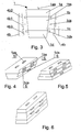
- Figure 3 presents the front view of the head with the platform strips
- Figures 4, 5, and 6 present schematically other exemplary embodiments of the head.
- connection system for charging batteries of a vehicle which, according to one of many possible exemplary embodiments of the invention, is designed for use in an electric bus, includes the head 1 which is mounted through the ball-and-socket joint 2 on the lifting mechanism 3 arranged in the form of the pantograph installed on the vehicle roof D , and the platform 4 mating with said head 1 and installed on the structural member K located outside the vehicle.
- the head 1 is of prismatic shape which, through detachable connections known in the art, is formed by mechanically connected dielectric holders of the PE contact segment 1a , the positive pole high-current contact segment 1b , the negative pole high-current contact segments 1c , and the communication contact segment 1d .
- the electrical brushes 1as , 1bs , 1cs , and 1ds are mounted slidably on springs S .
- the electrical brushes 1as , 1bs , 1cs , and 1ds in their extreme positions protrude from the holder surfaces.
- the brushes 1as of the PE contact segment protrude from the top surface of the head 1
- the brushes 1bs of the positive pole high-current contact segment 1b the brushes 1cs of the negative pole high-current contact segment 1c and the brush 1ds of the communication contact segment 1d protrude from two opposite side surfaces of the head 1 .
- the platform 4 is constituted by the body 4a inside which two dielectric strips 4b are mounted in parallel to the opposite sides of the body 4a and slidably in the direction perpendicular to these sides of the body 4a .
- the negative pole high-current contact rail 4b1 In the strip 4b the negative pole high-current contact rail 4b1 , the positive pole high-current contact rail 4b2 and the communication contact rail 4b3 are mounted.
- Each strip 4b is connected with its individual driving mechanism 4c mounted in the body 1 .
- the inner surface 4pw of the wall which covers the body 4a from above is electrically conductive and constitutes a PE contact.
- the brushes 1bs of the positive pole high-current contact segment 1b , the brushes 1cs of the negative pole high-current contact segment 1c and the brush 1ds of the communication contact segment 1d are in contact with the surface of the positive pole high-current contact rail 4b2 , the surface of the negative pole high-current contact rail 4b1 and the surface of the communication contact rail 4b3 , respectively.
- the opposite surfaces along which the head 1 contacts with the strip 4b are mutually parallel and deviate from vertical plane.
- the head 1 thanks to its being mounted through the ball-and-socket joint 2 , has the number of degrees of freedom required for its correct connection with the platform 4 in natural working conditions of the connection system, like ruts in roadway pavement, kneeling of the bus, and non-ideally parallel positioning of the bus with respect to the axis of the power supplying platform. Sliding movement of the strip 4b in the body 4a is possible thanks to longitudinal bearings that support the ends of the strips 4b .
- the communication contacts 1d and communication contact rails 4b3 are used mostly for checking continuity of the PE circuit in the entire charging system, i.e. the charging device + the bus.
- a post or any other architectural element may be used, provided it meets the technical requirements concerning assembly, possibility to connect a wire bundle, as well as strength properties.
- the dimensions of the platform 4 under which the driver must park the bus ensure full range of bus stopping tolerance.
- the platform 4 has the shape of a rectangle with dimensions of approximately 1000 mm x 2000 mm, which gives the tolerance of a bus stopping point within the range of 200 cm (front - rear) and 80 cm (left - right). It is the advantage that is not featured in other solutions that require the driver to position the vehicle very precisely with respect to power supply contacts.
- the invention allows for stopping the bus in a proper position without the need for using complex optical aiming systems or proximity sensors that can contribute to the increased frequency of failures. Another factor which ensures reliable and safe connection of the pantograph charging system is the shape of the connection system head 1 .
- the charging procedure Upon stopping the bus the charging procedure is activated from the level of the bus control panel or it is activated automatically, and the driver only permits to start the charging process.
- the charging process is completed according to the following steps:
- Communication between the charging device and the bus during the charging process can be realized wirelessly or using wires through the communication contacts that enable connection of the CAN bus in the connection system head 1 and in the platform 4 .
- the charging process can be finished: automatically as soon as the battery has been fully loaded, loaded to the level which can be defined in system settings, intentionally by the driver from the level of the bus control panel by removing the charging enable signal, or, finally, in emergency situations from the level of the bus or of the charger. Both closing and opening of charging contacts takes place in current-free and potential-free conditions.
Landscapes
- Engineering & Computer Science (AREA)
- Power Engineering (AREA)
- Transportation (AREA)
- Mechanical Engineering (AREA)
- Electric Propulsion And Braking For Vehicles (AREA)
- Current-Collector Devices For Electrically Propelled Vehicles (AREA)
- Arrangement Or Mounting Of Propulsion Units For Vehicles (AREA)
Abstract
Description
- The present invention concerns a design of a connection system for charging batteries of a vehicle, particularly an electric bus.
- Electric vehicles, in particular electric buses, are becoming a transportation means which is more and more frequently used in municipal transport services. However, for conversion of city transportation services to electric vehicles it is necessary to deploy technical means for recharging traction batteries in the vehicles in possibly shortest time. It results in a need for construction of very high power charging stations. To ensure operational safety and comfort of such charging stations, a charging method is needed which would limit human attendance in the battery charging procedure.
- From publication
WO2012118422 a connection system for charging bus batteries is known, comprising a head equipped with brushes of current carrying contacts and mounted on a pantograph installed on a vehicle roof, and a platform mating with the said head and installed on a structural member located outside the vehicle. The platform is equipped with high-current carrying rails and special devices for positioning of the head which mates with it. - However, the disadvantage of known solutions of connection systems for charging the batteries of vehicles is that in order to ensure correct connection of high-current contacts in the head with high-current contacts in the platform, either the bus driver has to manoeuvre the vehicle very precisely when approaching the platform, which is rather arduous, or complicated aiming devices must be used which, due to their complexity, are not very reliable and often fail, particularly in adverse weather conditions.
- The purpose of the invention is to provide a design of a connection system allowing the process of accelerated charging electric buses to be performed safely and reliably; moreover this mechanism is, to a maximum possible extent, easy to operate and reduces the need of precise manoeuvring of a bus during approaching the platform, thus improving the ergonomics of work of a city line bus driver.
- The essence of the design of the connection system for charging batteries of a vehicle, particularly an electric bus, which according to the invention comprises, at least, a head equipped with brushes and mounted on a pantograph or another lifting mechanism installed on a vehicle roof, and further comprises a platform mating with the head, equipped with electric contacts and installed on a structural member located outside the vehicle, is characterised in that the head is connected with the lifting mechanism through a ball-and-socket joint, while the head is of basically prismatic shape and is formed by mechanically connected dielectric holders of a PE contact segment, a positive pole high-current contact segment, a negative pole high-current contact segment, and a communication contact segment, and inside each holder the electrical brushes are mounted slidably on springs. The electrical brushes in their extreme positions protrude from the holder surfaces. The brushes of the PE contact segment protrude from the top surface of the head. The brushes of the positive pole high-current contact segment, the brushes of the negative pole high-current contact segment and the brush of the communication contact segment protrude from the same side surface of the head or from two opposite side surfaces of the head. A platform is constituted by a body inside which at least one dielectric strip is mounted in parallel to the opposite sides of the body and slidably in the direction perpendicular to these sides of the body. This strip is connected with a driving mechanism mounted in the body. The strip holds a negative pole high-current contact rail, a positive pole high-current contact rail and a communication contact rail. The inner surface of the wall which covers the body from above is electrically conductive and is grounded. When the strip is in such a position that it is in contact with the side surface of the head, the brushes of the positive pole high-current contact segment, the brushes of the negative pole high-current contact segment and the brush of the communication contact segment are in contact with the surface of the positive pole high-current contact rail; the surface of the negative pole high-current contact rail and the surface of the communication contact rail, respectively. According to another preferable feature of the invention, inside the body two dielectric strips are mounted in parallel to the opposite sides of the body and slidably in the direction perpendicular to these sides; moreover, each strip is connected with its individual driving mechanism mounted in the body, while in each strip the negative pole high-current contact rail, the positive pole high-current contact rail and the communication contact rail are mounted. According to further preferable feature of the invention, the opposite surfaces along which the head contacts with the strip surfaces are mutually parallel. According to another preferable feature of the invention, the opposite surfaces along which the head contacts with the strip deviate from vertical plane.
- The subject of the invention will now be described in more detail, based on an example of one of many possible embodiments, with reference to drawings, where
Figure 1 presents the general layout of the head and the platform,Figure 2 presents the schematic diagram of the platform,Figure 3 presents the front view of the head with the platform strips, andFigures 4, 5, and 6 present schematically other exemplary embodiments of the head. - The design of the connection system for charging batteries of a vehicle, which, according to one of many possible exemplary embodiments of the invention, is designed for use in an electric bus, includes the
head 1 which is mounted through the ball-and-socket joint 2 on thelifting mechanism 3 arranged in the form of the pantograph installed on the vehicle roof D , and theplatform 4 mating with saidhead 1 and installed on the structural member K located outside the vehicle. Thehead 1 is of prismatic shape which, through detachable connections known in the art, is formed by mechanically connected dielectric holders of thePE contact segment 1a, the positive pole high-current contact segment 1b, the negative pole high-current contact segments 1c, and thecommunication contact segment 1d. Inside thedielectric holders 1a the electrical brushes 1as, 1bs , 1cs , and 1ds are mounted slidably on springs S. The electrical brushes 1as, 1bs , 1cs , and 1ds in their extreme positions protrude from the holder surfaces. The brushes 1as of the PE contact segment protrude from the top surface of thehead 1, while the brushes 1bs of the positive pole high-current contact segment 1b, the brushes 1cs of the negative pole high-current contact segment 1c and the brush 1ds of thecommunication contact segment 1d protrude from two opposite side surfaces of thehead 1. Theplatform 4 is constituted by thebody 4a inside which twodielectric strips 4b are mounted in parallel to the opposite sides of thebody 4a and slidably in the direction perpendicular to these sides of thebody 4a. In thestrip 4b the negative pole high-current contact rail 4b1, the positive pole high-current contact rail 4b2 and the communication contact rail 4b3 are mounted. Eachstrip 4b is connected with itsindividual driving mechanism 4c mounted in thebody 1. The inner surface 4pw of the wall which covers thebody 4a from above is electrically conductive and constitutes a PE contact. When thestrip 4b is in such a position that it is in contact with the side surface of thehead 1, the brushes 1bs of the positive pole high-current contact segment 1b, the brushes 1cs of the negative pole high-current contact segment 1c and the brush 1ds of thecommunication contact segment 1d are in contact with the surface of the positive pole high-current contact rail 4b2 , the surface of the negative pole high-current contact rail 4b1 and the surface of the communication contact rail 4b3 , respectively. The opposite surfaces along which thehead 1 contacts with thestrip 4b are mutually parallel and deviate from vertical plane. - The
head 1 , thanks to its being mounted through the ball-and-socket joint 2, has the number of degrees of freedom required for its correct connection with theplatform 4 in natural working conditions of the connection system, like ruts in roadway pavement, kneeling of the bus, and non-ideally parallel positioning of the bus with respect to the axis of the power supplying platform. Sliding movement of thestrip 4b in thebody 4a is possible thanks to longitudinal bearings that support the ends of thestrips 4b. Thecommunication contacts 1d and communication contact rails 4b3 are used mostly for checking continuity of the PE circuit in the entire charging system, i.e. the charging device + the bus. As a structural member K located outside the vehicle, a post or any other architectural element may be used, provided it meets the technical requirements concerning assembly, possibility to connect a wire bundle, as well as strength properties. The dimensions of theplatform 4 under which the driver must park the bus ensure full range of bus stopping tolerance. Theplatform 4 has the shape of a rectangle with dimensions of approximately 1000 mm x 2000 mm, which gives the tolerance of a bus stopping point within the range of 200 cm (front - rear) and 80 cm (left - right). It is the advantage that is not featured in other solutions that require the driver to position the vehicle very precisely with respect to power supply contacts. The invention allows for stopping the bus in a proper position without the need for using complex optical aiming systems or proximity sensors that can contribute to the increased frequency of failures. Another factor which ensures reliable and safe connection of the pantograph charging system is the shape of theconnection system head 1. - Upon stopping the bus the charging procedure is activated from the level of the bus control panel or it is activated automatically, and the driver only permits to start the charging process. The charging process is completed according to the following steps:
- Prior to connecting, the DC charger communicates wirelessly with the electric bus;
- Then the mechanical arm of the pantograph extends the
head 1 towards theplatform 4 situated on an appropriate height; - The PE contacts close first and at that time the surfaces of the brushes 1as of the
PE contacts 1a are pressed against the inner surface 4pw of the wall which covers thebody 4a from above; - Further, upon the action of suitable force exerted by the
driving mechanism 4c, high-current contact rails 4b1 and 4b2 are pressed against the brushes of high-current contacts 1cs and 1bs , and communication contacts 1ds and 4b3 used for checking the continuity of the PE circuit are closed; if there is no continuity in the circuit, the charging process starting procedure is aborted. - Communication between the charging device and the bus during the charging process can be realized wirelessly or using wires through the communication contacts that enable connection of the CAN bus in the
connection system head 1 and in theplatform 4 . The charging process can be finished: automatically as soon as the battery has been fully loaded, loaded to the level which can be defined in system settings, intentionally by the driver from the level of the bus control panel by removing the charging enable signal, or, finally, in emergency situations from the level of the bus or of the charger. Both closing and opening of charging contacts takes place in current-free and potential-free conditions.
Claims (4)
- Design of a connection system for charging batteries of a vehicle, particularly an electric bus, comprising at least a head equipped with brushes and mounted on a lifting mechanism installed on a vehicle roof, further comprising a platform mating with the head, equipped with electric contacts and installed on a structural member located outside the vehicle, characterised in that the head ( 1 ) is connected with the lifting mechanism ( 3 ) through a ball-and-socket joint (2), while the head ( 1 ) of basically prismatic shape is formed by mechanically connected dielectric holders of a PE contact segment ( 1a ), a positive pole high-current contact segment (1b), a negative pole high-current contact segment ( 1c ) and a communication contact segment (1d), inside which respective electrical brushes ( 1as, 1bs, 1cs, and 1ds ) are mounted slidably on springs ( S ), whereas the electrical brushes ( 1as, 1bs, 1cs, and 1ds ) in their extreme positions protrude from the holder surfaces, furthermore the brushes ( 1as ) of the PE contact segment ( 1a ) protrude from the top surface of the head ( 1 ), the brushes ( 1bs ) of the positive pole high-current contact segment ( 1b ), the brushes ( 1cs ) of the negative pole high-current contact segment ( 1c ) and the brushes ( 1ds ) of the communication contact segment ( 1d ) protrude from the same side surface of the head ( 1 ) or from two opposite side surfaces of the head, furthermore the platform ( 3 ) is constituted by a body ( 4a ) inside which at least one dielectric strip ( 4b ) is mounted in parallel to the opposite sides of the body ( 4a ) and slidably in the direction perpendicular to these sides of the body, furthermore the strip ( 4b ) is connected with a driving mechanism ( 4c ) mounted in the body ( 4a ), while the strip ( 4b ) holds a negative pole high-current contact rail ( 4b1 ), a positive pole high-current contact rail ( 4b2 ), and a communication contact rail ( 4b3 ), furthermore the inner surface (4pw) of the wall which covers the body ( 4a ) from above is electrically conductive, and also, when the strip ( 4b ) is in such a position that it is in contact with the side surface of the head 1 , the brushes 1bs of the positive pole high-current contact segment 1b , the brushes 1cs of the negative pole high-current contact segment 1c and the brushes 1ds of the communication contact segment 1d are in contact with the surface of the positive pole high-current contact rail 4b2, the surface of the negative pole high-current contact rail 4b1 and the surface of the communication contact rail 4b3, respectively.
- Design of the connection system for charging batteries according to Claim 1, characterised in that inside the body two dielectric strips ( 4b ) are mounted in parallel to the opposite sides of the body ( 4a ) and slidably in the direction perpendicular to these sides of the body, furthermore each strip ( 4b ) is connected with its individual driving mechanism ( 4c ) mounted in the body ( 4a ), while in each strip ( 4b ) the negative pole high-current contact rail ( 4b1 ), the positive pole high-current contact rail ( 4b2 ) and the communication contact rail ( 4b3 ) are mounted.
- Design of the connection system for charging batteries according to Claim 1 or 2, characterised in that the opposite surfaces along which the head ( 1 ) contacts with the strip ( 4b ) surfaces are mutually parallel.
- Design of the connection system for charging batteries according to Claim 1, or 2, or 3, characterised in that the opposite surfaces along which the head ( 1 ) contacts with the strip ( 4b ) deviate from vertical plane.
Applications Claiming Priority (1)
| Application Number | Priority Date | Filing Date | Title |
|---|---|---|---|
| PL405342A PL224554B1 (en) | 2013-09-15 | 2013-09-15 | Construction of a connection for charging the vehicle accumulators, preferably of electric bus |
Publications (2)
| Publication Number | Publication Date |
|---|---|
| EP2848451A1 true EP2848451A1 (en) | 2015-03-18 |
| EP2848451B1 EP2848451B1 (en) | 2017-10-18 |
Family
ID=51868177
Family Applications (1)
| Application Number | Title | Priority Date | Filing Date |
|---|---|---|---|
| EP14460057.4A Active EP2848451B1 (en) | 2013-09-15 | 2014-09-15 | Connection system for charging batteries of a vehicle, particularly an electric bus |
Country Status (3)
| Country | Link |
|---|---|
| EP (1) | EP2848451B1 (en) |
| ES (1) | ES2653416T3 (en) |
| PL (1) | PL224554B1 (en) |
Cited By (8)
| Publication number | Priority date | Publication date | Assignee | Title |
|---|---|---|---|---|
| CN105416081A (en) * | 2015-12-03 | 2016-03-23 | 康迪电动汽车(长兴)有限公司 | Automatic charging system of electric car |
| CN109050309A (en) * | 2018-08-15 | 2018-12-21 | 江苏万帮德和新能源科技股份有限公司 | A kind of charging bow and charging method |
| CN109080489A (en) * | 2018-08-28 | 2018-12-25 | 江苏万帮德和新能源科技股份有限公司 | Charge mobile mechanism and charging unit |
| CN109677286A (en) * | 2018-12-07 | 2019-04-26 | 北京中车赛德铁道电气科技有限公司 | A kind of position control and adjustment mode of inversion type charging bow |
| WO2019153923A1 (en) * | 2018-02-06 | 2019-08-15 | 比亚迪股份有限公司 | Charging apparatus for railway vehicle, and rail traffic system |
| CN110696628A (en) * | 2019-09-06 | 2020-01-17 | 上海宝冶冶金工程有限公司 | Torpedo tank car electric energy supply system |
| CN111301208A (en) * | 2020-02-28 | 2020-06-19 | 国充充电科技江苏股份有限公司 | Pantograph charging station group charging control system and method |
| CN111867875A (en) * | 2018-03-15 | 2020-10-30 | 申克运输系统有限责任公司 | Fast charging system and method for electrically connecting a vehicle to a charging station |
Families Citing this family (1)
| Publication number | Priority date | Publication date | Assignee | Title |
|---|---|---|---|---|
| PL247361B1 (en) | 2021-09-30 | 2025-06-16 | Ec Eng Spolka Z Ograniczona Odpowiedzialnoscia | Contact head for a current collector adapted for charging electric vehicles, a fast charging system for electric vehicles, and a method for creating an electrically conductive connection between a charging station and the contact head |
Citations (6)
| Publication number | Priority date | Publication date | Assignee | Title |
|---|---|---|---|---|
| JP2006081310A (en) * | 2004-09-09 | 2006-03-23 | Matsushita Electric Works Ltd | Feeder device |
| DE102004048226A1 (en) * | 2004-09-27 | 2006-04-13 | Fraunhofer-Gesellschaft zur Förderung der angewandten Forschung e.V. | Battery charging system, for vehicles such as buses or trams, has contacts arranged in carriageway boundary member and accessed by charging arm system of vehicle |
| CN101580023A (en) * | 2009-06-18 | 2009-11-18 | 上海交通大学 | Single pole rotation type public transportation trolley bus trolley-pole |
| WO2010134763A2 (en) * | 2009-05-22 | 2010-11-25 | 주식회사 레오모터스 | Battery-charging apparatus for an electric vehicle |
| WO2012118422A1 (en) | 2010-11-03 | 2012-09-07 | Boh Westerlund | Conductor system |
| US20130193919A1 (en) * | 2008-07-01 | 2013-08-01 | Proterra Inc. | Methods and Systems for Charging Vehicles |
-
2013
- 2013-09-15 PL PL405342A patent/PL224554B1/en unknown
-
2014
- 2014-09-15 EP EP14460057.4A patent/EP2848451B1/en active Active
- 2014-09-15 ES ES14460057.4T patent/ES2653416T3/en active Active
Patent Citations (6)
| Publication number | Priority date | Publication date | Assignee | Title |
|---|---|---|---|---|
| JP2006081310A (en) * | 2004-09-09 | 2006-03-23 | Matsushita Electric Works Ltd | Feeder device |
| DE102004048226A1 (en) * | 2004-09-27 | 2006-04-13 | Fraunhofer-Gesellschaft zur Förderung der angewandten Forschung e.V. | Battery charging system, for vehicles such as buses or trams, has contacts arranged in carriageway boundary member and accessed by charging arm system of vehicle |
| US20130193919A1 (en) * | 2008-07-01 | 2013-08-01 | Proterra Inc. | Methods and Systems for Charging Vehicles |
| WO2010134763A2 (en) * | 2009-05-22 | 2010-11-25 | 주식회사 레오모터스 | Battery-charging apparatus for an electric vehicle |
| CN101580023A (en) * | 2009-06-18 | 2009-11-18 | 上海交通大学 | Single pole rotation type public transportation trolley bus trolley-pole |
| WO2012118422A1 (en) | 2010-11-03 | 2012-09-07 | Boh Westerlund | Conductor system |
Cited By (10)
| Publication number | Priority date | Publication date | Assignee | Title |
|---|---|---|---|---|
| CN105416081A (en) * | 2015-12-03 | 2016-03-23 | 康迪电动汽车(长兴)有限公司 | Automatic charging system of electric car |
| CN105416081B (en) * | 2015-12-03 | 2017-12-19 | 康迪电动汽车(长兴)有限公司 | A kind of automatic charging system of electric automobile |
| WO2019153923A1 (en) * | 2018-02-06 | 2019-08-15 | 比亚迪股份有限公司 | Charging apparatus for railway vehicle, and rail traffic system |
| CN111867875A (en) * | 2018-03-15 | 2020-10-30 | 申克运输系统有限责任公司 | Fast charging system and method for electrically connecting a vehicle to a charging station |
| CN109050309A (en) * | 2018-08-15 | 2018-12-21 | 江苏万帮德和新能源科技股份有限公司 | A kind of charging bow and charging method |
| CN109080489A (en) * | 2018-08-28 | 2018-12-25 | 江苏万帮德和新能源科技股份有限公司 | Charge mobile mechanism and charging unit |
| CN109677286A (en) * | 2018-12-07 | 2019-04-26 | 北京中车赛德铁道电气科技有限公司 | A kind of position control and adjustment mode of inversion type charging bow |
| CN110696628A (en) * | 2019-09-06 | 2020-01-17 | 上海宝冶冶金工程有限公司 | Torpedo tank car electric energy supply system |
| CN111301208A (en) * | 2020-02-28 | 2020-06-19 | 国充充电科技江苏股份有限公司 | Pantograph charging station group charging control system and method |
| CN111301208B (en) * | 2020-02-28 | 2022-02-08 | 国充充电科技江苏股份有限公司 | Pantograph charging station group charging control system and method |
Also Published As
| Publication number | Publication date |
|---|---|
| PL224554B1 (en) | 2017-01-31 |
| PL405342A1 (en) | 2015-03-16 |
| EP2848451B1 (en) | 2017-10-18 |
| ES2653416T3 (en) | 2018-02-07 |
Similar Documents
| Publication | Publication Date | Title |
|---|---|---|
| EP2848451B1 (en) | Connection system for charging batteries of a vehicle, particularly an electric bus | |
| AU2014246942B2 (en) | Connecting apparatus for connecting an electrically powered vehicle to a charging station | |
| CN107298023B (en) | Vehicle charging connector | |
| EP3256341B1 (en) | Contacting device and rapid charging system | |
| CN104169121B (en) | Current transmission device for charging an electric energy store of a vehicle at an overhead charging station | |
| US9969299B2 (en) | Traffic system and power supply method | |
| US20170210238A1 (en) | Vehicle Charging Station Comprising A Supply-Contact Device Mounted On An Arm | |
| CN105244933B (en) | Externally chargeable vehicle with electric drive and charging station for the vehicle | |
| US20170217324A1 (en) | Vehicle charging station with an articulated arm | |
| CN106536262B (en) | Charging equipment for rechargeable vehicle | |
| US11712969B2 (en) | Current collector device for a vehicle | |
| CN105339203A (en) | Protection arrangement for an electric vehicle | |
| WO2014207540A2 (en) | Overhead changing arrangement for a vehicle | |
| US12384253B2 (en) | Electrical vehicle comprising an energy transfer device | |
| CN113748045A (en) | Interchangeable energy device for electric vehicle | |
| CN114987252A (en) | Aerial crane type automobile mobile charging pile system and working method thereof | |
| EP2981432B1 (en) | Connecting apparatus for connecting an electrically powered vehicle to a charging station |
Legal Events
| Date | Code | Title | Description |
|---|---|---|---|
| PUAI | Public reference made under article 153(3) epc to a published international application that has entered the european phase |
Free format text: ORIGINAL CODE: 0009012 |
|
| 17P | Request for examination filed |
Effective date: 20140915 |
|
| AK | Designated contracting states |
Kind code of ref document: A1 Designated state(s): AL AT BE BG CH CY CZ DE DK EE ES FI FR GB GR HR HU IE IS IT LI LT LU LV MC MK MT NL NO PL PT RO RS SE SI SK SM TR |
|
| AX | Request for extension of the european patent |
Extension state: BA ME |
|
| R17P | Request for examination filed (corrected) |
Effective date: 20150803 |
|
| RBV | Designated contracting states (corrected) |
Designated state(s): AL AT BE BG CH CY CZ DE DK EE ES FI FR GB GR HR HU IE IS IT LI LT LU LV MC MK MT NL NO PL PT RO RS SE SI SK SM TR |
|
| GRAP | Despatch of communication of intention to grant a patent |
Free format text: ORIGINAL CODE: EPIDOSNIGR1 |
|
| INTG | Intention to grant announced |
Effective date: 20170303 |
|
| RIN1 | Information on inventor provided before grant (corrected) |
Inventor name: WOJENSKI, MACIEJ Inventor name: MICHALAK, DARIUSZ, KICIN Inventor name: HOLODOK, ARTUR Inventor name: KUBIK, BARTOSZ Inventor name: SIERSZYNSKI, MICHAL Inventor name: PIKULA, MICHAL |
|
| GRAS | Grant fee paid |
Free format text: ORIGINAL CODE: EPIDOSNIGR3 |
|
| GRAJ | Information related to disapproval of communication of intention to grant by the applicant or resumption of examination proceedings by the epo deleted |
Free format text: ORIGINAL CODE: EPIDOSDIGR1 |
|
| GRAL | Information related to payment of fee for publishing/printing deleted |
Free format text: ORIGINAL CODE: EPIDOSDIGR3 |
|
| RIN1 | Information on inventor provided before grant (corrected) |
Inventor name: HOLODOK, ARTUR Inventor name: WOJENSKI, MACIEJ Inventor name: PIKULA, MICHAL Inventor name: SIERSZYNSKI, MICHAL Inventor name: KUBIK, BARTOSZ Inventor name: MICHALAK, DARIUSZ, |
|
| INTC | Intention to grant announced (deleted) | ||
| GRAR | Information related to intention to grant a patent recorded |
Free format text: ORIGINAL CODE: EPIDOSNIGR71 |
|
| GRAA | (expected) grant |
Free format text: ORIGINAL CODE: 0009210 |
|
| INTG | Intention to grant announced |
Effective date: 20170907 |
|
| AK | Designated contracting states |
Kind code of ref document: B1 Designated state(s): AL AT BE BG CH CY CZ DE DK EE ES FI FR GB GR HR HU IE IS IT LI LT LU LV MC MK MT NL NO PL PT RO RS SE SI SK SM TR |
|
| REG | Reference to a national code |
Ref country code: GB Ref legal event code: FG4D |
|
| REG | Reference to a national code |
Ref country code: CH Ref legal event code: EP |
|
| REG | Reference to a national code |
Ref country code: AT Ref legal event code: REF Ref document number: 937610 Country of ref document: AT Kind code of ref document: T Effective date: 20171115 Ref country code: IE Ref legal event code: FG4D |
|
| RIN2 | Information on inventor provided after grant (corrected) |
Inventor name: HOLODOK, ARTUR Inventor name: PIKULA, MICHAL Inventor name: SIERSZYNSKI, MICHAL Inventor name: MICHALAK, DARIUSZ, Inventor name: KUBIK, BARTOSZ Inventor name: WOJENSKI, MACIEJ |
|
| REG | Reference to a national code |
Ref country code: DE Ref legal event code: R096 Ref document number: 602014015923 Country of ref document: DE |
|
| REG | Reference to a national code |
Ref country code: SE Ref legal event code: TRGR |
|
| RAP2 | Party data changed (patent owner data changed or rights of a patent transferred) |
Owner name: EKOENERGETYKA - POLSKA SP. Z O.O. Owner name: SOLARIS BUS & COACH S.A. |
|
| REG | Reference to a national code |
Ref country code: NL Ref legal event code: FP |
|
| REG | Reference to a national code |
Ref country code: ES Ref legal event code: FG2A Ref document number: 2653416 Country of ref document: ES Kind code of ref document: T3 Effective date: 20180207 |
|
| REG | Reference to a national code |
Ref country code: LT Ref legal event code: MG4D |
|
| REG | Reference to a national code |
Ref country code: AT Ref legal event code: MK05 Ref document number: 937610 Country of ref document: AT Kind code of ref document: T Effective date: 20171018 |
|
| REG | Reference to a national code |
Ref country code: SK Ref legal event code: T3 Ref document number: E 26177 Country of ref document: SK |
|
| PG25 | Lapsed in a contracting state [announced via postgrant information from national office to epo] |
Ref country code: NO Free format text: LAPSE BECAUSE OF FAILURE TO SUBMIT A TRANSLATION OF THE DESCRIPTION OR TO PAY THE FEE WITHIN THE PRESCRIBED TIME-LIMIT Effective date: 20180118 Ref country code: LT Free format text: LAPSE BECAUSE OF FAILURE TO SUBMIT A TRANSLATION OF THE DESCRIPTION OR TO PAY THE FEE WITHIN THE PRESCRIBED TIME-LIMIT Effective date: 20171018 Ref country code: FI Free format text: LAPSE BECAUSE OF FAILURE TO SUBMIT A TRANSLATION OF THE DESCRIPTION OR TO PAY THE FEE WITHIN THE PRESCRIBED TIME-LIMIT Effective date: 20171018 |
|
| PG25 | Lapsed in a contracting state [announced via postgrant information from national office to epo] |
Ref country code: RS Free format text: LAPSE BECAUSE OF FAILURE TO SUBMIT A TRANSLATION OF THE DESCRIPTION OR TO PAY THE FEE WITHIN THE PRESCRIBED TIME-LIMIT Effective date: 20171018 Ref country code: HR Free format text: LAPSE BECAUSE OF FAILURE TO SUBMIT A TRANSLATION OF THE DESCRIPTION OR TO PAY THE FEE WITHIN THE PRESCRIBED TIME-LIMIT Effective date: 20171018 Ref country code: AT Free format text: LAPSE BECAUSE OF FAILURE TO SUBMIT A TRANSLATION OF THE DESCRIPTION OR TO PAY THE FEE WITHIN THE PRESCRIBED TIME-LIMIT Effective date: 20171018 Ref country code: IS Free format text: LAPSE BECAUSE OF FAILURE TO SUBMIT A TRANSLATION OF THE DESCRIPTION OR TO PAY THE FEE WITHIN THE PRESCRIBED TIME-LIMIT Effective date: 20180218 Ref country code: BG Free format text: LAPSE BECAUSE OF FAILURE TO SUBMIT A TRANSLATION OF THE DESCRIPTION OR TO PAY THE FEE WITHIN THE PRESCRIBED TIME-LIMIT Effective date: 20180118 Ref country code: GR Free format text: LAPSE BECAUSE OF FAILURE TO SUBMIT A TRANSLATION OF THE DESCRIPTION OR TO PAY THE FEE WITHIN THE PRESCRIBED TIME-LIMIT Effective date: 20180119 Ref country code: LV Free format text: LAPSE BECAUSE OF FAILURE TO SUBMIT A TRANSLATION OF THE DESCRIPTION OR TO PAY THE FEE WITHIN THE PRESCRIBED TIME-LIMIT Effective date: 20171018 |
|
| REG | Reference to a national code |
Ref country code: DE Ref legal event code: R097 Ref document number: 602014015923 Country of ref document: DE |
|
| REG | Reference to a national code |
Ref country code: FR Ref legal event code: PLFP Year of fee payment: 5 |
|
| PG25 | Lapsed in a contracting state [announced via postgrant information from national office to epo] |
Ref country code: EE Free format text: LAPSE BECAUSE OF FAILURE TO SUBMIT A TRANSLATION OF THE DESCRIPTION OR TO PAY THE FEE WITHIN THE PRESCRIBED TIME-LIMIT Effective date: 20171018 Ref country code: DK Free format text: LAPSE BECAUSE OF FAILURE TO SUBMIT A TRANSLATION OF THE DESCRIPTION OR TO PAY THE FEE WITHIN THE PRESCRIBED TIME-LIMIT Effective date: 20171018 |
|
| PLBE | No opposition filed within time limit |
Free format text: ORIGINAL CODE: 0009261 |
|
| STAA | Information on the status of an ep patent application or granted ep patent |
Free format text: STATUS: NO OPPOSITION FILED WITHIN TIME LIMIT |
|
| PG25 | Lapsed in a contracting state [announced via postgrant information from national office to epo] |
Ref country code: RO Free format text: LAPSE BECAUSE OF FAILURE TO SUBMIT A TRANSLATION OF THE DESCRIPTION OR TO PAY THE FEE WITHIN THE PRESCRIBED TIME-LIMIT Effective date: 20171018 Ref country code: SM Free format text: LAPSE BECAUSE OF FAILURE TO SUBMIT A TRANSLATION OF THE DESCRIPTION OR TO PAY THE FEE WITHIN THE PRESCRIBED TIME-LIMIT Effective date: 20171018 Ref country code: PL Free format text: LAPSE BECAUSE OF FAILURE TO SUBMIT A TRANSLATION OF THE DESCRIPTION OR TO PAY THE FEE WITHIN THE PRESCRIBED TIME-LIMIT Effective date: 20171018 |
|
| 26N | No opposition filed |
Effective date: 20180719 |
|
| PG25 | Lapsed in a contracting state [announced via postgrant information from national office to epo] |
Ref country code: SI Free format text: LAPSE BECAUSE OF FAILURE TO SUBMIT A TRANSLATION OF THE DESCRIPTION OR TO PAY THE FEE WITHIN THE PRESCRIBED TIME-LIMIT Effective date: 20171018 |
|
| PG25 | Lapsed in a contracting state [announced via postgrant information from national office to epo] |
Ref country code: MC Free format text: LAPSE BECAUSE OF FAILURE TO SUBMIT A TRANSLATION OF THE DESCRIPTION OR TO PAY THE FEE WITHIN THE PRESCRIBED TIME-LIMIT Effective date: 20171018 |
|
| REG | Reference to a national code |
Ref country code: CH Ref legal event code: PL |
|
| REG | Reference to a national code |
Ref country code: BE Ref legal event code: MM Effective date: 20180930 |
|
| REG | Reference to a national code |
Ref country code: IE Ref legal event code: MM4A |
|
| PG25 | Lapsed in a contracting state [announced via postgrant information from national office to epo] |
Ref country code: LU Free format text: LAPSE BECAUSE OF NON-PAYMENT OF DUE FEES Effective date: 20180915 |
|
| PG25 | Lapsed in a contracting state [announced via postgrant information from national office to epo] |
Ref country code: IE Free format text: LAPSE BECAUSE OF NON-PAYMENT OF DUE FEES Effective date: 20180915 |
|
| PG25 | Lapsed in a contracting state [announced via postgrant information from national office to epo] |
Ref country code: CH Free format text: LAPSE BECAUSE OF NON-PAYMENT OF DUE FEES Effective date: 20180930 Ref country code: LI Free format text: LAPSE BECAUSE OF NON-PAYMENT OF DUE FEES Effective date: 20180930 Ref country code: BE Free format text: LAPSE BECAUSE OF NON-PAYMENT OF DUE FEES Effective date: 20180930 |
|
| PG25 | Lapsed in a contracting state [announced via postgrant information from national office to epo] |
Ref country code: MT Free format text: LAPSE BECAUSE OF NON-PAYMENT OF DUE FEES Effective date: 20180915 |
|
| PG25 | Lapsed in a contracting state [announced via postgrant information from national office to epo] |
Ref country code: TR Free format text: LAPSE BECAUSE OF FAILURE TO SUBMIT A TRANSLATION OF THE DESCRIPTION OR TO PAY THE FEE WITHIN THE PRESCRIBED TIME-LIMIT Effective date: 20171018 |
|
| PG25 | Lapsed in a contracting state [announced via postgrant information from national office to epo] |
Ref country code: HU Free format text: LAPSE BECAUSE OF FAILURE TO SUBMIT A TRANSLATION OF THE DESCRIPTION OR TO PAY THE FEE WITHIN THE PRESCRIBED TIME-LIMIT; INVALID AB INITIO Effective date: 20140915 Ref country code: PT Free format text: LAPSE BECAUSE OF FAILURE TO SUBMIT A TRANSLATION OF THE DESCRIPTION OR TO PAY THE FEE WITHIN THE PRESCRIBED TIME-LIMIT Effective date: 20171018 |
|
| PG25 | Lapsed in a contracting state [announced via postgrant information from national office to epo] |
Ref country code: CY Free format text: LAPSE BECAUSE OF FAILURE TO SUBMIT A TRANSLATION OF THE DESCRIPTION OR TO PAY THE FEE WITHIN THE PRESCRIBED TIME-LIMIT Effective date: 20171018 Ref country code: MK Free format text: LAPSE BECAUSE OF NON-PAYMENT OF DUE FEES Effective date: 20171018 |
|
| PG25 | Lapsed in a contracting state [announced via postgrant information from national office to epo] |
Ref country code: AL Free format text: LAPSE BECAUSE OF FAILURE TO SUBMIT A TRANSLATION OF THE DESCRIPTION OR TO PAY THE FEE WITHIN THE PRESCRIBED TIME-LIMIT Effective date: 20171018 |
|
| REG | Reference to a national code |
Ref country code: DE Ref legal event code: R081 Ref document number: 602014015923 Country of ref document: DE Owner name: EKOENERGETYKA -POLSKA SPOLKA AKCYJNA, PL Free format text: FORMER OWNERS: EKOENERGETYKA - POLSKA SP. Z O.O., ZIELONA GORA, PL; SOLARIS BUS & COACH S.A., OWINSKA, PL Ref country code: DE Ref legal event code: R081 Ref document number: 602014015923 Country of ref document: DE Owner name: SOLARIS BUS & COACH SP. Z O.O., PL Free format text: FORMER OWNERS: EKOENERGETYKA - POLSKA SP. Z O.O., ZIELONA GORA, PL; SOLARIS BUS & COACH S.A., OWINSKA, PL |
|
| REG | Reference to a national code |
Ref country code: NL Ref legal event code: PD Owner name: SOLARIS BUS & COACH SPOLKA Z OGRANICZONA ODPOWIEDZIALNOSCIA; PL Free format text: DETAILS ASSIGNMENT: CHANGE OF OWNER(S), CHANGE OF LEGAL ENTITY; FORMER OWNER NAME: SOLARIS BUS & COACH S.A. Effective date: 20201218 |
|
| REG | Reference to a national code |
Ref country code: ES Ref legal event code: PC2A Owner name: EKOENERGETYKA - POLSKA SPOLKA AKCYJNA Effective date: 20210121 |
|
| REG | Reference to a national code |
Ref country code: SK Ref legal event code: TC4A Ref document number: E 26177 Country of ref document: SK Owner name: SOLARIS BUS & COACH SPOLKA Z OGRANICZONA ODPOW, PL Effective date: 20210111 Ref country code: SK Ref legal event code: TC4A Ref document number: E 26177 Country of ref document: SK Owner name: EKOENERGETYKA - POLSKA SPOLKA AKCYJNA, ZIELONA, PL Effective date: 20210111 |
|
| PGFP | Annual fee paid to national office [announced via postgrant information from national office to epo] |
Ref country code: DE Payment date: 20240905 Year of fee payment: 11 |
|
| PGFP | Annual fee paid to national office [announced via postgrant information from national office to epo] |
Ref country code: GB Payment date: 20240905 Year of fee payment: 11 |
|
| PGFP | Annual fee paid to national office [announced via postgrant information from national office to epo] |
Ref country code: FR Payment date: 20240823 Year of fee payment: 11 |
|
| PGFP | Annual fee paid to national office [announced via postgrant information from national office to epo] |
Ref country code: NL Payment date: 20240905 Year of fee payment: 11 |
|
| PGFP | Annual fee paid to national office [announced via postgrant information from national office to epo] |
Ref country code: CZ Payment date: 20240905 Year of fee payment: 11 |
|
| PGFP | Annual fee paid to national office [announced via postgrant information from national office to epo] |
Ref country code: SK Payment date: 20240905 Year of fee payment: 11 |
|
| PGFP | Annual fee paid to national office [announced via postgrant information from national office to epo] |
Ref country code: SE Payment date: 20240906 Year of fee payment: 11 Ref country code: IT Payment date: 20240905 Year of fee payment: 11 |
|
| PGFP | Annual fee paid to national office [announced via postgrant information from national office to epo] |
Ref country code: ES Payment date: 20251126 Year of fee payment: 12 |
|
| PG25 | Lapsed in a contracting state [announced via postgrant information from national office to epo] |
Ref country code: CZ Free format text: LAPSE BECAUSE OF NON-PAYMENT OF DUE FEES Effective date: 20250915 |
|
| REG | Reference to a national code |
Ref country code: SK Ref legal event code: MM4A Ref document number: E 26177 Country of ref document: SK Effective date: 20250915 |