EP2848445A1 - Electric vehicle - Google Patents
Electric vehicle Download PDFInfo
- Publication number
- EP2848445A1 EP2848445A1 EP20120876122 EP12876122A EP2848445A1 EP 2848445 A1 EP2848445 A1 EP 2848445A1 EP 20120876122 EP20120876122 EP 20120876122 EP 12876122 A EP12876122 A EP 12876122A EP 2848445 A1 EP2848445 A1 EP 2848445A1
- Authority
- EP
- European Patent Office
- Prior art keywords
- inverter
- drive train
- vehicle
- bracket
- motor
- Prior art date
- Legal status (The legal status is an assumption and is not a legal conclusion. Google has not performed a legal analysis and makes no representation as to the accuracy of the status listed.)
- Granted
Links
Images



Classifications
-
- B—PERFORMING OPERATIONS; TRANSPORTING
- B60—VEHICLES IN GENERAL
- B60K—ARRANGEMENT OR MOUNTING OF PROPULSION UNITS OR OF TRANSMISSIONS IN VEHICLES; ARRANGEMENT OR MOUNTING OF PLURAL DIVERSE PRIME-MOVERS IN VEHICLES; AUXILIARY DRIVES FOR VEHICLES; INSTRUMENTATION OR DASHBOARDS FOR VEHICLES; ARRANGEMENTS IN CONNECTION WITH COOLING, AIR INTAKE, GAS EXHAUST OR FUEL SUPPLY OF PROPULSION UNITS IN VEHICLES
- B60K1/00—Arrangement or mounting of electrical propulsion units
- B60K1/04—Arrangement or mounting of electrical propulsion units of the electric storage means for propulsion
-
- B—PERFORMING OPERATIONS; TRANSPORTING
- B60—VEHICLES IN GENERAL
- B60K—ARRANGEMENT OR MOUNTING OF PROPULSION UNITS OR OF TRANSMISSIONS IN VEHICLES; ARRANGEMENT OR MOUNTING OF PLURAL DIVERSE PRIME-MOVERS IN VEHICLES; AUXILIARY DRIVES FOR VEHICLES; INSTRUMENTATION OR DASHBOARDS FOR VEHICLES; ARRANGEMENTS IN CONNECTION WITH COOLING, AIR INTAKE, GAS EXHAUST OR FUEL SUPPLY OF PROPULSION UNITS IN VEHICLES
- B60K1/00—Arrangement or mounting of electrical propulsion units
-
- B—PERFORMING OPERATIONS; TRANSPORTING
- B60—VEHICLES IN GENERAL
- B60K—ARRANGEMENT OR MOUNTING OF PROPULSION UNITS OR OF TRANSMISSIONS IN VEHICLES; ARRANGEMENT OR MOUNTING OF PLURAL DIVERSE PRIME-MOVERS IN VEHICLES; AUXILIARY DRIVES FOR VEHICLES; INSTRUMENTATION OR DASHBOARDS FOR VEHICLES; ARRANGEMENTS IN CONNECTION WITH COOLING, AIR INTAKE, GAS EXHAUST OR FUEL SUPPLY OF PROPULSION UNITS IN VEHICLES
- B60K6/00—Arrangement or mounting of plural diverse prime-movers for mutual or common propulsion, e.g. hybrid propulsion systems comprising electric motors and internal combustion engines
- B60K6/20—Arrangement or mounting of plural diverse prime-movers for mutual or common propulsion, e.g. hybrid propulsion systems comprising electric motors and internal combustion engines the prime-movers consisting of electric motors and internal combustion engines, e.g. HEVs
- B60K6/22—Arrangement or mounting of plural diverse prime-movers for mutual or common propulsion, e.g. hybrid propulsion systems comprising electric motors and internal combustion engines the prime-movers consisting of electric motors and internal combustion engines, e.g. HEVs characterised by apparatus, components or means specially adapted for HEVs
- B60K6/40—Arrangement or mounting of plural diverse prime-movers for mutual or common propulsion, e.g. hybrid propulsion systems comprising electric motors and internal combustion engines the prime-movers consisting of electric motors and internal combustion engines, e.g. HEVs characterised by apparatus, components or means specially adapted for HEVs characterised by the assembly or relative disposition of components
-
- B—PERFORMING OPERATIONS; TRANSPORTING
- B60—VEHICLES IN GENERAL
- B60L—PROPULSION OF ELECTRICALLY-PROPELLED VEHICLES; SUPPLYING ELECTRIC POWER FOR AUXILIARY EQUIPMENT OF ELECTRICALLY-PROPELLED VEHICLES; ELECTRODYNAMIC BRAKE SYSTEMS FOR VEHICLES IN GENERAL; MAGNETIC SUSPENSION OR LEVITATION FOR VEHICLES; MONITORING OPERATING VARIABLES OF ELECTRICALLY-PROPELLED VEHICLES; ELECTRIC SAFETY DEVICES FOR ELECTRICALLY-PROPELLED VEHICLES
- B60L15/00—Methods, circuits, or devices for controlling the traction-motor speed of electrically-propelled vehicles
- B60L15/20—Methods, circuits, or devices for controlling the traction-motor speed of electrically-propelled vehicles for control of the vehicle or its driving motor to achieve a desired performance, e.g. speed, torque, programmed variation of speed
-
- B—PERFORMING OPERATIONS; TRANSPORTING
- B60—VEHICLES IN GENERAL
- B60L—PROPULSION OF ELECTRICALLY-PROPELLED VEHICLES; SUPPLYING ELECTRIC POWER FOR AUXILIARY EQUIPMENT OF ELECTRICALLY-PROPELLED VEHICLES; ELECTRODYNAMIC BRAKE SYSTEMS FOR VEHICLES IN GENERAL; MAGNETIC SUSPENSION OR LEVITATION FOR VEHICLES; MONITORING OPERATING VARIABLES OF ELECTRICALLY-PROPELLED VEHICLES; ELECTRIC SAFETY DEVICES FOR ELECTRICALLY-PROPELLED VEHICLES
- B60L15/00—Methods, circuits, or devices for controlling the traction-motor speed of electrically-propelled vehicles
- B60L15/20—Methods, circuits, or devices for controlling the traction-motor speed of electrically-propelled vehicles for control of the vehicle or its driving motor to achieve a desired performance, e.g. speed, torque, programmed variation of speed
- B60L15/2009—Methods, circuits, or devices for controlling the traction-motor speed of electrically-propelled vehicles for control of the vehicle or its driving motor to achieve a desired performance, e.g. speed, torque, programmed variation of speed for braking
-
- B—PERFORMING OPERATIONS; TRANSPORTING
- B60—VEHICLES IN GENERAL
- B60L—PROPULSION OF ELECTRICALLY-PROPELLED VEHICLES; SUPPLYING ELECTRIC POWER FOR AUXILIARY EQUIPMENT OF ELECTRICALLY-PROPELLED VEHICLES; ELECTRODYNAMIC BRAKE SYSTEMS FOR VEHICLES IN GENERAL; MAGNETIC SUSPENSION OR LEVITATION FOR VEHICLES; MONITORING OPERATING VARIABLES OF ELECTRICALLY-PROPELLED VEHICLES; ELECTRIC SAFETY DEVICES FOR ELECTRICALLY-PROPELLED VEHICLES
- B60L3/00—Electric devices on electrically-propelled vehicles for safety purposes; Monitoring operating variables, e.g. speed, deceleration or energy consumption
- B60L3/0007—Measures or means for preventing or attenuating collisions
-
- B—PERFORMING OPERATIONS; TRANSPORTING
- B60—VEHICLES IN GENERAL
- B60L—PROPULSION OF ELECTRICALLY-PROPELLED VEHICLES; SUPPLYING ELECTRIC POWER FOR AUXILIARY EQUIPMENT OF ELECTRICALLY-PROPELLED VEHICLES; ELECTRODYNAMIC BRAKE SYSTEMS FOR VEHICLES IN GENERAL; MAGNETIC SUSPENSION OR LEVITATION FOR VEHICLES; MONITORING OPERATING VARIABLES OF ELECTRICALLY-PROPELLED VEHICLES; ELECTRIC SAFETY DEVICES FOR ELECTRICALLY-PROPELLED VEHICLES
- B60L3/00—Electric devices on electrically-propelled vehicles for safety purposes; Monitoring operating variables, e.g. speed, deceleration or energy consumption
- B60L3/0023—Detecting, eliminating, remedying or compensating for drive train abnormalities, e.g. failures within the drive train
- B60L3/003—Detecting, eliminating, remedying or compensating for drive train abnormalities, e.g. failures within the drive train relating to inverters
-
- B—PERFORMING OPERATIONS; TRANSPORTING
- B60—VEHICLES IN GENERAL
- B60L—PROPULSION OF ELECTRICALLY-PROPELLED VEHICLES; SUPPLYING ELECTRIC POWER FOR AUXILIARY EQUIPMENT OF ELECTRICALLY-PROPELLED VEHICLES; ELECTRODYNAMIC BRAKE SYSTEMS FOR VEHICLES IN GENERAL; MAGNETIC SUSPENSION OR LEVITATION FOR VEHICLES; MONITORING OPERATING VARIABLES OF ELECTRICALLY-PROPELLED VEHICLES; ELECTRIC SAFETY DEVICES FOR ELECTRICALLY-PROPELLED VEHICLES
- B60L50/00—Electric propulsion with power supplied within the vehicle
- B60L50/10—Electric propulsion with power supplied within the vehicle using propulsion power supplied by engine-driven generators, e.g. generators driven by combustion engines
- B60L50/16—Electric propulsion with power supplied within the vehicle using propulsion power supplied by engine-driven generators, e.g. generators driven by combustion engines with provision for separate direct mechanical propulsion
-
- B—PERFORMING OPERATIONS; TRANSPORTING
- B60—VEHICLES IN GENERAL
- B60L—PROPULSION OF ELECTRICALLY-PROPELLED VEHICLES; SUPPLYING ELECTRIC POWER FOR AUXILIARY EQUIPMENT OF ELECTRICALLY-PROPELLED VEHICLES; ELECTRODYNAMIC BRAKE SYSTEMS FOR VEHICLES IN GENERAL; MAGNETIC SUSPENSION OR LEVITATION FOR VEHICLES; MONITORING OPERATING VARIABLES OF ELECTRICALLY-PROPELLED VEHICLES; ELECTRIC SAFETY DEVICES FOR ELECTRICALLY-PROPELLED VEHICLES
- B60L50/00—Electric propulsion with power supplied within the vehicle
- B60L50/50—Electric propulsion with power supplied within the vehicle using propulsion power supplied by batteries or fuel cells
- B60L50/51—Electric propulsion with power supplied within the vehicle using propulsion power supplied by batteries or fuel cells characterised by AC-motors
-
- B—PERFORMING OPERATIONS; TRANSPORTING
- B60—VEHICLES IN GENERAL
- B60L—PROPULSION OF ELECTRICALLY-PROPELLED VEHICLES; SUPPLYING ELECTRIC POWER FOR AUXILIARY EQUIPMENT OF ELECTRICALLY-PROPELLED VEHICLES; ELECTRODYNAMIC BRAKE SYSTEMS FOR VEHICLES IN GENERAL; MAGNETIC SUSPENSION OR LEVITATION FOR VEHICLES; MONITORING OPERATING VARIABLES OF ELECTRICALLY-PROPELLED VEHICLES; ELECTRIC SAFETY DEVICES FOR ELECTRICALLY-PROPELLED VEHICLES
- B60L50/00—Electric propulsion with power supplied within the vehicle
- B60L50/50—Electric propulsion with power supplied within the vehicle using propulsion power supplied by batteries or fuel cells
- B60L50/60—Electric propulsion with power supplied within the vehicle using propulsion power supplied by batteries or fuel cells using power supplied by batteries
- B60L50/61—Electric propulsion with power supplied within the vehicle using propulsion power supplied by batteries or fuel cells using power supplied by batteries by batteries charged by engine-driven generators, e.g. series hybrid electric vehicles
-
- B—PERFORMING OPERATIONS; TRANSPORTING
- B60—VEHICLES IN GENERAL
- B60L—PROPULSION OF ELECTRICALLY-PROPELLED VEHICLES; SUPPLYING ELECTRIC POWER FOR AUXILIARY EQUIPMENT OF ELECTRICALLY-PROPELLED VEHICLES; ELECTRODYNAMIC BRAKE SYSTEMS FOR VEHICLES IN GENERAL; MAGNETIC SUSPENSION OR LEVITATION FOR VEHICLES; MONITORING OPERATING VARIABLES OF ELECTRICALLY-PROPELLED VEHICLES; ELECTRIC SAFETY DEVICES FOR ELECTRICALLY-PROPELLED VEHICLES
- B60L50/00—Electric propulsion with power supplied within the vehicle
- B60L50/50—Electric propulsion with power supplied within the vehicle using propulsion power supplied by batteries or fuel cells
- B60L50/60—Electric propulsion with power supplied within the vehicle using propulsion power supplied by batteries or fuel cells using power supplied by batteries
- B60L50/66—Arrangements of batteries
-
- B—PERFORMING OPERATIONS; TRANSPORTING
- B60—VEHICLES IN GENERAL
- B60L—PROPULSION OF ELECTRICALLY-PROPELLED VEHICLES; SUPPLYING ELECTRIC POWER FOR AUXILIARY EQUIPMENT OF ELECTRICALLY-PROPELLED VEHICLES; ELECTRODYNAMIC BRAKE SYSTEMS FOR VEHICLES IN GENERAL; MAGNETIC SUSPENSION OR LEVITATION FOR VEHICLES; MONITORING OPERATING VARIABLES OF ELECTRICALLY-PROPELLED VEHICLES; ELECTRIC SAFETY DEVICES FOR ELECTRICALLY-PROPELLED VEHICLES
- B60L58/00—Methods or circuit arrangements for monitoring or controlling batteries or fuel cells, specially adapted for electric vehicles
- B60L58/10—Methods or circuit arrangements for monitoring or controlling batteries or fuel cells, specially adapted for electric vehicles for monitoring or controlling batteries
- B60L58/18—Methods or circuit arrangements for monitoring or controlling batteries or fuel cells, specially adapted for electric vehicles for monitoring or controlling batteries of two or more battery modules
- B60L58/20—Methods or circuit arrangements for monitoring or controlling batteries or fuel cells, specially adapted for electric vehicles for monitoring or controlling batteries of two or more battery modules having different nominal voltages
-
- B—PERFORMING OPERATIONS; TRANSPORTING
- B60—VEHICLES IN GENERAL
- B60L—PROPULSION OF ELECTRICALLY-PROPELLED VEHICLES; SUPPLYING ELECTRIC POWER FOR AUXILIARY EQUIPMENT OF ELECTRICALLY-PROPELLED VEHICLES; ELECTRODYNAMIC BRAKE SYSTEMS FOR VEHICLES IN GENERAL; MAGNETIC SUSPENSION OR LEVITATION FOR VEHICLES; MONITORING OPERATING VARIABLES OF ELECTRICALLY-PROPELLED VEHICLES; ELECTRIC SAFETY DEVICES FOR ELECTRICALLY-PROPELLED VEHICLES
- B60L7/00—Electrodynamic brake systems for vehicles in general
- B60L7/10—Dynamic electric regenerative braking
- B60L7/14—Dynamic electric regenerative braking for vehicles propelled by AC motors
-
- B—PERFORMING OPERATIONS; TRANSPORTING
- B60—VEHICLES IN GENERAL
- B60K—ARRANGEMENT OR MOUNTING OF PROPULSION UNITS OR OF TRANSMISSIONS IN VEHICLES; ARRANGEMENT OR MOUNTING OF PLURAL DIVERSE PRIME-MOVERS IN VEHICLES; AUXILIARY DRIVES FOR VEHICLES; INSTRUMENTATION OR DASHBOARDS FOR VEHICLES; ARRANGEMENTS IN CONNECTION WITH COOLING, AIR INTAKE, GAS EXHAUST OR FUEL SUPPLY OF PROPULSION UNITS IN VEHICLES
- B60K1/00—Arrangement or mounting of electrical propulsion units
- B60K1/04—Arrangement or mounting of electrical propulsion units of the electric storage means for propulsion
- B60K2001/0405—Arrangement or mounting of electrical propulsion units of the electric storage means for propulsion characterised by their position
- B60K2001/0411—Arrangement in the front part of the vehicle
-
- B—PERFORMING OPERATIONS; TRANSPORTING
- B60—VEHICLES IN GENERAL
- B60L—PROPULSION OF ELECTRICALLY-PROPELLED VEHICLES; SUPPLYING ELECTRIC POWER FOR AUXILIARY EQUIPMENT OF ELECTRICALLY-PROPELLED VEHICLES; ELECTRODYNAMIC BRAKE SYSTEMS FOR VEHICLES IN GENERAL; MAGNETIC SUSPENSION OR LEVITATION FOR VEHICLES; MONITORING OPERATING VARIABLES OF ELECTRICALLY-PROPELLED VEHICLES; ELECTRIC SAFETY DEVICES FOR ELECTRICALLY-PROPELLED VEHICLES
- B60L2210/00—Converter types
- B60L2210/40—DC to AC converters
-
- B—PERFORMING OPERATIONS; TRANSPORTING
- B60—VEHICLES IN GENERAL
- B60L—PROPULSION OF ELECTRICALLY-PROPELLED VEHICLES; SUPPLYING ELECTRIC POWER FOR AUXILIARY EQUIPMENT OF ELECTRICALLY-PROPELLED VEHICLES; ELECTRODYNAMIC BRAKE SYSTEMS FOR VEHICLES IN GENERAL; MAGNETIC SUSPENSION OR LEVITATION FOR VEHICLES; MONITORING OPERATING VARIABLES OF ELECTRICALLY-PROPELLED VEHICLES; ELECTRIC SAFETY DEVICES FOR ELECTRICALLY-PROPELLED VEHICLES
- B60L2240/00—Control parameters of input or output; Target parameters
- B60L2240/40—Drive Train control parameters
- B60L2240/42—Drive Train control parameters related to electric machines
- B60L2240/423—Torque
-
- B—PERFORMING OPERATIONS; TRANSPORTING
- B60—VEHICLES IN GENERAL
- B60L—PROPULSION OF ELECTRICALLY-PROPELLED VEHICLES; SUPPLYING ELECTRIC POWER FOR AUXILIARY EQUIPMENT OF ELECTRICALLY-PROPELLED VEHICLES; ELECTRODYNAMIC BRAKE SYSTEMS FOR VEHICLES IN GENERAL; MAGNETIC SUSPENSION OR LEVITATION FOR VEHICLES; MONITORING OPERATING VARIABLES OF ELECTRICALLY-PROPELLED VEHICLES; ELECTRIC SAFETY DEVICES FOR ELECTRICALLY-PROPELLED VEHICLES
- B60L2240/00—Control parameters of input or output; Target parameters
- B60L2240/40—Drive Train control parameters
- B60L2240/44—Drive Train control parameters related to combustion engines
- B60L2240/443—Torque
-
- B—PERFORMING OPERATIONS; TRANSPORTING
- B60—VEHICLES IN GENERAL
- B60L—PROPULSION OF ELECTRICALLY-PROPELLED VEHICLES; SUPPLYING ELECTRIC POWER FOR AUXILIARY EQUIPMENT OF ELECTRICALLY-PROPELLED VEHICLES; ELECTRODYNAMIC BRAKE SYSTEMS FOR VEHICLES IN GENERAL; MAGNETIC SUSPENSION OR LEVITATION FOR VEHICLES; MONITORING OPERATING VARIABLES OF ELECTRICALLY-PROPELLED VEHICLES; ELECTRIC SAFETY DEVICES FOR ELECTRICALLY-PROPELLED VEHICLES
- B60L2240/00—Control parameters of input or output; Target parameters
- B60L2240/80—Time limits
-
- B—PERFORMING OPERATIONS; TRANSPORTING
- B60—VEHICLES IN GENERAL
- B60Y—INDEXING SCHEME RELATING TO ASPECTS CROSS-CUTTING VEHICLE TECHNOLOGY
- B60Y2306/00—Other features of vehicle sub-units
- B60Y2306/01—Reducing damages in case of crash, e.g. by improving battery protection
-
- B—PERFORMING OPERATIONS; TRANSPORTING
- B60—VEHICLES IN GENERAL
- B60Y—INDEXING SCHEME RELATING TO ASPECTS CROSS-CUTTING VEHICLE TECHNOLOGY
- B60Y2400/00—Special features of vehicle units
- B60Y2400/61—Arrangements of controllers for electric machines, e.g. inverters
-
- Y—GENERAL TAGGING OF NEW TECHNOLOGICAL DEVELOPMENTS; GENERAL TAGGING OF CROSS-SECTIONAL TECHNOLOGIES SPANNING OVER SEVERAL SECTIONS OF THE IPC; TECHNICAL SUBJECTS COVERED BY FORMER USPC CROSS-REFERENCE ART COLLECTIONS [XRACs] AND DIGESTS
- Y02—TECHNOLOGIES OR APPLICATIONS FOR MITIGATION OR ADAPTATION AGAINST CLIMATE CHANGE
- Y02T—CLIMATE CHANGE MITIGATION TECHNOLOGIES RELATED TO TRANSPORTATION
- Y02T10/00—Road transport of goods or passengers
- Y02T10/60—Other road transportation technologies with climate change mitigation effect
- Y02T10/62—Hybrid vehicles
-
- Y—GENERAL TAGGING OF NEW TECHNOLOGICAL DEVELOPMENTS; GENERAL TAGGING OF CROSS-SECTIONAL TECHNOLOGIES SPANNING OVER SEVERAL SECTIONS OF THE IPC; TECHNICAL SUBJECTS COVERED BY FORMER USPC CROSS-REFERENCE ART COLLECTIONS [XRACs] AND DIGESTS
- Y02—TECHNOLOGIES OR APPLICATIONS FOR MITIGATION OR ADAPTATION AGAINST CLIMATE CHANGE
- Y02T—CLIMATE CHANGE MITIGATION TECHNOLOGIES RELATED TO TRANSPORTATION
- Y02T10/00—Road transport of goods or passengers
- Y02T10/60—Other road transportation technologies with climate change mitigation effect
- Y02T10/64—Electric machine technologies in electromobility
-
- Y—GENERAL TAGGING OF NEW TECHNOLOGICAL DEVELOPMENTS; GENERAL TAGGING OF CROSS-SECTIONAL TECHNOLOGIES SPANNING OVER SEVERAL SECTIONS OF THE IPC; TECHNICAL SUBJECTS COVERED BY FORMER USPC CROSS-REFERENCE ART COLLECTIONS [XRACs] AND DIGESTS
- Y02—TECHNOLOGIES OR APPLICATIONS FOR MITIGATION OR ADAPTATION AGAINST CLIMATE CHANGE
- Y02T—CLIMATE CHANGE MITIGATION TECHNOLOGIES RELATED TO TRANSPORTATION
- Y02T10/00—Road transport of goods or passengers
- Y02T10/60—Other road transportation technologies with climate change mitigation effect
- Y02T10/70—Energy storage systems for electromobility, e.g. batteries
-
- Y—GENERAL TAGGING OF NEW TECHNOLOGICAL DEVELOPMENTS; GENERAL TAGGING OF CROSS-SECTIONAL TECHNOLOGIES SPANNING OVER SEVERAL SECTIONS OF THE IPC; TECHNICAL SUBJECTS COVERED BY FORMER USPC CROSS-REFERENCE ART COLLECTIONS [XRACs] AND DIGESTS
- Y02—TECHNOLOGIES OR APPLICATIONS FOR MITIGATION OR ADAPTATION AGAINST CLIMATE CHANGE
- Y02T—CLIMATE CHANGE MITIGATION TECHNOLOGIES RELATED TO TRANSPORTATION
- Y02T10/00—Road transport of goods or passengers
- Y02T10/60—Other road transportation technologies with climate change mitigation effect
- Y02T10/7072—Electromobility specific charging systems or methods for batteries, ultracapacitors, supercapacitors or double-layer capacitors
-
- Y—GENERAL TAGGING OF NEW TECHNOLOGICAL DEVELOPMENTS; GENERAL TAGGING OF CROSS-SECTIONAL TECHNOLOGIES SPANNING OVER SEVERAL SECTIONS OF THE IPC; TECHNICAL SUBJECTS COVERED BY FORMER USPC CROSS-REFERENCE ART COLLECTIONS [XRACs] AND DIGESTS
- Y02—TECHNOLOGIES OR APPLICATIONS FOR MITIGATION OR ADAPTATION AGAINST CLIMATE CHANGE
- Y02T—CLIMATE CHANGE MITIGATION TECHNOLOGIES RELATED TO TRANSPORTATION
- Y02T10/00—Road transport of goods or passengers
- Y02T10/60—Other road transportation technologies with climate change mitigation effect
- Y02T10/72—Electric energy management in electromobility
-
- Y—GENERAL TAGGING OF NEW TECHNOLOGICAL DEVELOPMENTS; GENERAL TAGGING OF CROSS-SECTIONAL TECHNOLOGIES SPANNING OVER SEVERAL SECTIONS OF THE IPC; TECHNICAL SUBJECTS COVERED BY FORMER USPC CROSS-REFERENCE ART COLLECTIONS [XRACs] AND DIGESTS
- Y10—TECHNICAL SUBJECTS COVERED BY FORMER USPC
- Y10S—TECHNICAL SUBJECTS COVERED BY FORMER USPC CROSS-REFERENCE ART COLLECTIONS [XRACs] AND DIGESTS
- Y10S903/00—Hybrid electric vehicles, HEVS
- Y10S903/902—Prime movers comprising electrical and internal combustion motors
- Y10S903/903—Prime movers comprising electrical and internal combustion motors having energy storing means, e.g. battery, capacitor
- Y10S903/951—Assembly or relative location of components
Definitions
- a technology disclosed herein relates to an electric vehicle.
- the electric vehicle herein includes a hybrid vehicle comprising both a motor and an engine and a fuel-cell vehicle.
- An electric vehicle includes a traction motor and an inverter configured to supply electric power to the motor. Since the traction motor has great rated power, a large current flows from the inverter to the motor. Therefore, it is preferable that the inverter be placed near the motor and that a cable (hereinafter referred to as "power cable") which connects the inverter and the motor be short. For example, in order to shorten the power cable, fixing an inverter to rear or top of a motor is proposed in Japanese Patent Application Publication No. 2004-328870 (Patent Literature 1).
- the motor and the inverter are installed in an engine room.
- the engine room In most automobiles, the engine room is located in a front part of a vehicle.
- the engine room in the front part of the vehicle is sometimes called a front compartment.
- the engine room in the front part of the vehicle is hereinafter referred to as "front compartment".
- front compartment There is a risk that a device placed in the front compartment may be damaged when the vehicle crashes. Even when the device is damaged, the vehicle may still be able to run in some cases if there is no breakage in the power cable. Therefore, a structure in which the power cable is protected from breakage is desirable even in the case where the vehicle is in a crash.
- Patent Literature 2 Japanese Patent Application Publication No. 2006-088871 A
- the technology disclosed in Patent Literature 2 is as follows: The inverter is fixed on a side member of a front compartment, and the motor is fixed on a suspension member located below the side member. The side member and the suspension member correspond to a vehicle body frame.
- the side member and the suspension member are both designed to bend toward a lower side of the vehicle when the vehicle crashes. Bending of the side member and the suspension member in the same direction prevents positions of the inverter and the motor relative to each other from changing at a great degree and reduces a possibility of the power cable breakage.
- Patent Literature 2 fixes the inverter and the motor to different members (namely to the side member and to the suspension member). If a deformation of the side member and a deformation of the suspension at the time of the crash are different, there is a risk that the distance between the inverter and the motor may be increased and the power cable is broken. Further, the technology of Patent Literature 2 makes it necessary to separately determine a fixing position of the inverter and a fixing position of the motor. This means low design flexibility.
- the present specification provides a structure in which a power cable is protected from breakage at the time of a crash by a different approach from Patent Literature 2.
- the technology disclosed herein relates to a placement of a drive train in a front compartment of an electric vehicle and of an inverter configured to supply the motor with AC power.
- the drive train is a structure housing a traction motor.
- the technology disclosed herein uses a front bracket and a rear bracket to fix the inverter on a top of the drive train with a gap provided therebetween.
- the front bracket connects a front surface of the inverter with the drive train
- the rear bracket connects a rear surface of the inverter with the drive train.
- the front surface of the inverter corresponds to a frontward side surface of the vehicle
- the rear surface of the inverter corresponds to a rearward side surface of the vehicle.
- a power cable is a cable routed between the inverter and the drive train, and through this cable, electric power is supplied from the inverter to the motor.
- the front and rear brackets deform so that the inverter sinks in the gap while moving backward.
- the deformation of the front and rear brackets buffers the impact while the inverter and the drive train move toward each other. Therefore, in the above structure, the possibility of a power cable breakage is low.
- the front bracket has a wavy shape between a fixing point on a drive train side and a fixing point on an inverter side as seen along a lateral direction of the vehicle.
- the wavy shape of the front bracket makes a movable distance of a forward part of the inverter be longer at the time of receiving impact from the front. This configuration makes it possible to absorb greater amount of the impact.
- Patent Literature 1 discloses a technology of fixing an inverter onto a motor by using a bracket.
- the inverter is fixed to the motor located directly below the center of the inverter. Therefore, there is a high possibility that the bracket breaks and the inverter comes off from the motor when impact is applied thereto from a front of the inverter.
- the bracket breaking and thereby causing the inverter to come off is low.
- the power cable extends from a rear surface of the inverter
- the power cable extends from a front surface of the inverter.
- the power cable extends from the rear surface of the inverter
- the power cable extends from the front surface of the inverter
- FIG. 1 and FIG. 2 show a layout of devices in a front compartment 94 of a hybrid vehicle 100.
- FIG. 1 is a perspective view of the front compartment 94
- FIG. 2 is a plan view of the front compartment 94.
- shapes of the devices in the front compartment 94 are shown in a simplified manner.
- an x axis corresponds to a frontward direction of the vehicle
- a y axis corresponds to a lateral direction of the vehicle
- a z axis corresponds to an upward direction of the vehicle.
- Main devices mounted in the front compartment 94 are an engine 97, a drive train 2, an auxiliary battery 6, a radiator 96, and an inverter 5 configured to supply a motor 3 with AC power.
- a reference sign 92 refers to a relay box
- a reference sign 93 refers to a compressor of an air conditioner.
- the first motor 3, a second motor 4, a transmission, and a differential gear are housed in the drive train 2.
- the first motor 3 and the second motor 4 are configured to drive the wheels.
- the transmission is configured to amplify output torques of the motors and of the engine. Therefore, it should be noted that the motors 3 and 4 are out of immediate sight in FIGS. 1 and 2 .
- the engine 97 and the drive train 2 are fixed to a side frame 95 (side member) configuring a frame of a chassis.
- the radiator 96 is fixed to a front frame 98 (front bumper reinforcement) configuring a part of the frame.
- a body 90 of the vehicle, too, is supported by the side frame 95 and the front frame 98.
- the hybrid vehicle switches between using the engine 97 and using the motor 3 or 4, depending on a situation.
- the hybrid vehicle uses the engine 97 and the two motors 3 and 4 as a driving source simultaneously. Otherwise, at least one of the motors is used as a generator for generating electric power.
- the transmission inside the drive train 2 switches between output from the engine 97 and output from the motor 3 or 4, or combines the outputs and transmits them to the differential gear.
- the transmission may transmit part of driving force of the engine 97 to the motor 3 or 4.
- the motor generates electricity by the driving force of the engine. That is, at least one of the two motors 3 and 4 functions also as a generator.
- the drive train 2 may be called a power train or a transaxle. A detailed structure of the drive train 2 is not described.
- the motor 3 or 4 may convert deceleration energy (regenerated energy) into electric energy when a brake is operated.
- the drive train 2 is a transaxle, commonly known as a multi-shaft type, for use in a hybrid vehicle.
- This drive train 2 contains two motors (or motor generators) and a differential gear. Main shafts of the two motors and a shaft of the differential gear extend in parallel with each other. Further, an upper surface of the drive train 2 leans forward.
- the inverter 5 is fixed to the forward-leaning upper surface.
- the inverter 5 is fixed to the upper surface of the drive train 2 with a gap by a front bracket 12 and a rear bracket 13.
- a connector 21 for cables (power cables) configured to supply the motors with AC power is attached on a lateral side surface in a lateral direction of the inverter 5. Since the hybrid vehicle 100 includes the two three-phase drive motors 3 and 4, six power cables (UVW x two sets) extend from the inverter 5.
- the auxiliary battery 6 is located at a left front of the inverter 5.
- the auxiliary battery 6 supplies low-power devices such as a car audio system and a room lamp with electric power.
- a high-output main battery for the traction motors 3 and 4 is housed under a rear seat or in a rear compartment.
- a corner protector 14 is attached to a left upper corner portion of the inverter 5 that faces the auxiliary battery 6. At the time of a crash, an obstacle may collide with the auxiliary battery 6 and the auxiliary battery 6 may move backward toward the inverter 5. The corner protector 14 protects the inverter 5 from the auxiliary battery 6 at the time of the crash.
- the auxiliary battery 6 is fixed to the side frame 95 by a metal fitting 15 and a rubber belt 31.
- the metal fitting 15 surrounds lateral sides of the auxiliary battery 6 and an upper side of the auxiliary battery 6 and the auxiliary battery 6 is fixed by hanging the rubber belt 31 being stretched from below on a hook 15a which is a tip of the metal fitting 15.
- a protector 12p extends laterally from the front bracket 12 in order to protect the power cables from the hook 15a when the auxiliary battery 6 moves backward at the time of the crash.
- FIG. 3 shows a side view of the drive train 2 and the inverter 5 fixed to a top of the drive train 2.
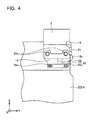
- FIG. 4 shows a front view of the inverter 5 fixed to the top of the drive train 2
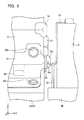
- FIG. 5 shows a rear view of the inverter 5 fixed to the top of the drive train 2.
- FIG. 3 omits to illustrate the protector 12p.
- the drive train 2 is a multi-shaft type in which main shafts 2a and 2b of the two motors 3 and 4 and a shaft 2c of the differential gear extend parallel to each other in the lateral direction of the vehicle. The upper surface of the drive train 2 leans forward.
- the inverter 5 is fixed by the front bracket 12 and the rear bracket 13 to the forward-leaning upper surface.
- the front bracket 12 and the rear bracket 13 are made, for example, of iron.
- the front bracket 12 fixes the front surface of the inverter 5 and the rear bracket 13 fixes the rear surface of the inverter 5.
- the inverter 5, too, is fixed in such a manner as to lean forward.
- the front bracket 12 has two fixing points, one on the right and the other on the left on a drive train side, and is fixed by bolts 25c at these two fixing points, respectively.
- the front bracket 12 also has two more fixing points, one on the right and the other on the left on an inverter side, and is fixed by bolts 25a at these two fixing points, respectively.
- the rear bracket 13 has two fixing points, one on the right and the other on the left on the drive train side, and is fixed by bolts 25d at these two fixing points, respectively.
- the rear bracket 13 also has two more fixing points, one on the right and the other on the left on the inverter side, and is fixed by bolts 25b at these two fixing points, respectively.
- the bolts 25a and the bolts 25b, fixing the inverter 5 extend along a front and rear direction of the vehicle. It should be noted that “faced along a front and rear direction of the vehicle” needs only to mean extending substantially along the front and rear direction of the vehicle. Strictly speaking, the bolts 25a and 25b are screwed into the inverter 5 at a same angle as an angle at which the inverter 5 leans forward.
- the front bracket 12 has a wavy shape between the fixing points on the drive train side and the fixing points on the inverter side as seen along a lateral direction of the vehicle.
- One connector 21 for one side of power cables 22 is attached to a side surface of the inverter 5 in the lateral direction of the vehicle.
- Another connector 23 for the other side of the power cables 22 is attached to the leaning upper surface of the drive train 2.
- the connector 23 is located directly below the inverter 5.
- the power cables 22configured to supply the motors 3 and 4 with electric power extend from the side surface of the inverter in the lateral direction of the vehicle and are connected to the upper surface of the drive train 2.
- a gap G is provided between the upper surface of the drive train 2 and a lower surface of the inverter 5.
- a configuration of the front bracket 12, the rear bracket 13, and the gap G lowers a possibility of any of the power cables 22 breaking when the vehicle crashes.
- a reference sign F in FIG.3 represents impact that is applied to the inverter 5 when the vehicle crashes. When the impact indicated by the reference sign F is applied to a forward part of the inverter 5, the front bracket 12 and the rear bracket 13 fall backward and the inverter 5 sinks in the gap G while moving backward. That is, the inverter 5 moves backward and downward when the inverter 5 receives the impact from the forward part.
- An arrow A in FIG. 3 indicates the movement of the inverter 5.
- Deformations of the front bracket 12 and the rear bracket 13 and the movement of the inverter 5 alleviate the impact. Furthermore, the inverter 5 approaches toward the upper surface of the drive train 2 when the inverter 5 moves in a direction indicated by the arrow A. That is, a distance between the connector 21 and the connector 23 is reduced. Therefore, a risk of a breakage in any of the power cables 22 at the time of the crash is low.
- the front bracket 12 has a wavy shape as seen from the lateral side of the vehicle.
- the wavy portion stretches out to allow the front part of the inverter 5 to move over a longer distance.
- the wavy portion 12a of the front bracket 12 contributes to the alleviation of the impact of the crash.
- FIG. 6 is a front view of a part of the inverter 5 and the auxiliary battery 6.
- the auxiliary battery 6 is fixed to the side member 95 by the metal fitting 15 and the rubber belt 31.
- the metal fitting 15 has a tip bent to configure the hook 15a.
- the auxiliary battery 6 is fixed by the rubber belt 31, which extends from the side member 95, being hung on the hook 15a.
- the protector 12p is located so as to overlap with the hook 15a as seen from the front of the vehicle (also see FIG. 2 ). Further, the hook 15a is located in front of the protector 12p and the power cables 22 are located behind the protector 12p. That is, the protector 12p is located between the hook 15a and the power cables 22 in the front and rear direction of the vehicle.
- an obstacle may collide with the auxiliary battery 6 and the auxiliary battery 6 may move backward. In that case, if there is no protector 12p, there is a risk that the hook 15a might move backward to the power cables 22 to break any of the power cables 22.
- the protector 12p located between the hook 15a and the power cables 22, protects the power cables 22 from the hook 15a.
- the hybrid vehicle 100 of the embodiment has the following features.
- the upper surface of the drive train 2 leans forward.
- the inverter 5 is fixed to the top of the drive train 2 with the gap G by the front bracket 12 and the rear bracket 13.
- the power cables 22 configured to supply the motors 3 and 4 with electric power extend to the upper surface of the drive train 2 from the side surface of the inverter 5 in the lateral direction of the vehicle.
- the inverter 5 is fixed to the upper surface of the drive train 2 in a forward-leaning position.
- the inverter 5 is fixed in the forward-leaning position with the gap G therebelow; therefore, when the forward part of the inverter 5 receives impact, the front bracket 12 and the rear bracket 13 deform and the inverter 5 sinks in the gap G while moving backward.
- the front bracket 12 and the rear bracket 13 permit the inverter 5 to move slightly toward the drive train 2 so that any of the power cables 22 do not break. This alleviates the impact. Furthermore, since the inverter 5 sinks into the gap G, the distance between the inverter 5 and the drive train 2 becomes shorter. The possibility of any of the power cables 22 breaking is therefore low even if the vehicle crashes and an obstacle collides with the front surface of the inverter 5.
- the front bracket 12 has the wavy shape (portion indicated by the reference sign 12a in FIG. 3 ) between the fixing points on the drive train 2 side and the fixing points on the inverter 5 side as seen along the lateral direction of the vehicle.
- the wavy portion 12a stretches. This increases an amount of deformation of the front bracket 12, thus further alleviating the impact.
- the inverter 5 leans forward. Therefore, when an obstacle collides with the front surface of the inverter 5, the inverter 5 is highly likely to move toward the drive train 2. This also contributes to a break proof of any of the power cables 22.
- the front bracket 12 and the front surface of the inverter 5 are fixed to each other by the bolts 25a, and the rear bracket 13 and the rear surface of the inverter 5 are fixed to each other by the bolts 25b.
- the bolts 25a and 25b extend substantially along the front and rear direction of the vehicle. More strictly, the bolts 25a and 25b extend at the same angle as the angle at which the inverter 5 leans. Such a structure reduces a possibility of great shearing force being applied to the bolts when the vehicle crashes. Therefore, a possibility of the bolts 25a and 25b breaking when the vehicle crashes is low. That is, a possibility of the front and rear brackets coming off at the time of the crash is low.
- the power cables 22 configured to supply the motors 3 and 4 with electric power extend from the side surface in the lateral direction of the inverter 5.
- the protector 12p extends from a lateral side of the front bracket 12 into a space between the power cables 22 and the hook 15a at the tip of the metal fitting.
- the protector 12p protects the power cables 22 from being broken by the hook 15a at the tip of the metal fitting. It should be noted that the protector 12p is a part of the front bracket 12.
- the front bracket 12 has a wavy shape at a middle as seen along the lateral direction of the vehicle.
- the wavy portion (a region indicated by the reference sign 12a in FIG. 3 ) allows the inverter 5 to move in a longer distance at the time of impact. This also contributes to a reduction in the impact that is applied to the inverter 5.
- the power cables 22 extend from the side surface of the inverter 5 and are connected to the upper surface of the drive train 2. Such a structure also protects the power cables 22 from braking even in a case where the vehicle crashes and the inverter 5 moves.
- the electric vehicle of the embodiment is a hybrid vehicle including a motor and an engine.
- the technology disclosed herein can also be applied to an electric vehicle including no engine. Further, the technology disclosed herein is also suitably applied to a fuel-cell vehicle. In that case, the main battery corresponds to a fuel cell.
Landscapes
- Engineering & Computer Science (AREA)
- Transportation (AREA)
- Mechanical Engineering (AREA)
- Power Engineering (AREA)
- Life Sciences & Earth Sciences (AREA)
- Sustainable Development (AREA)
- Sustainable Energy (AREA)
- Chemical & Material Sciences (AREA)
- Combustion & Propulsion (AREA)
- Arrangement Or Mounting Of Propulsion Units For Vehicles (AREA)
- Electric Propulsion And Braking For Vehicles (AREA)
Abstract
Description
- A technology disclosed herein relates to an electric vehicle. The electric vehicle herein includes a hybrid vehicle comprising both a motor and an engine and a fuel-cell vehicle.
- An electric vehicle includes a traction motor and an inverter configured to supply electric power to the motor. Since the traction motor has great rated power, a large current flows from the inverter to the motor. Therefore, it is preferable that the inverter be placed near the motor and that a cable (hereinafter referred to as "power cable") which connects the inverter and the motor be short. For example, in order to shorten the power cable, fixing an inverter to rear or top of a motor is proposed in Japanese Patent Application Publication No.
2004-328870 - In order to place an inverter near a motor, the motor and the inverter are installed in an engine room. In most automobiles, the engine room is located in a front part of a vehicle. The engine room in the front part of the vehicle is sometimes called a front compartment. In this specification also, the engine room in the front part of the vehicle is hereinafter referred to as "front compartment". There is a risk that a device placed in the front compartment may be damaged when the vehicle crashes. Even when the device is damaged, the vehicle may still be able to run in some cases if there is no breakage in the power cable. Therefore, a structure in which the power cable is protected from breakage is desirable even in the case where the vehicle is in a crash.
- One of causes of the power cable breakage at the time of a crash is that the motor and/or the inverter moves backward and a distance between the motor and the inverter is increased by an impact of the crash. In this regard, an example of a structure in which the distance between a motor and an inverter is hardly increased at the time of a crash is disclosed in Japanese Patent Application Publication No.
2006-088871 A Patent Literature 2 is as follows: The inverter is fixed on a side member of a front compartment, and the motor is fixed on a suspension member located below the side member. The side member and the suspension member correspond to a vehicle body frame. The side member and the suspension member are both designed to bend toward a lower side of the vehicle when the vehicle crashes. Bending of the side member and the suspension member in the same direction prevents positions of the inverter and the motor relative to each other from changing at a great degree and reduces a possibility of the power cable breakage. - The technology described in
Patent Literature 2 fixes the inverter and the motor to different members (namely to the side member and to the suspension member). If a deformation of the side member and a deformation of the suspension at the time of the crash are different, there is a risk that the distance between the inverter and the motor may be increased and the power cable is broken. Further, the technology ofPatent Literature 2 makes it necessary to separately determine a fixing position of the inverter and a fixing position of the motor. This means low design flexibility. The present specification provides a structure in which a power cable is protected from breakage at the time of a crash by a different approach fromPatent Literature 2. - The technology disclosed herein relates to a placement of a drive train in a front compartment of an electric vehicle and of an inverter configured to supply the motor with AC power. The drive train is a structure housing a traction motor. The technology disclosed herein uses a front bracket and a rear bracket to fix the inverter on a top of the drive train with a gap provided therebetween. The front bracket connects a front surface of the inverter with the drive train, and the rear bracket connects a rear surface of the inverter with the drive train. It should be noted here that the front surface of the inverter corresponds to a frontward side surface of the vehicle, and the rear surface of the inverter corresponds to a rearward side surface of the vehicle. A power cable is a cable routed between the inverter and the drive train, and through this cable, electric power is supplied from the inverter to the motor.
- According to the above structure, when the vehicle crashes with an obstacle and the front surface of the inverter receives the impact, the front and rear brackets deform so that the inverter sinks in the gap while moving backward. The deformation of the front and rear brackets buffers the impact while the inverter and the drive train move toward each other. Therefore, in the above structure, the possibility of a power cable breakage is low.
- As a further improvement to the above structure, it is preferable that the front bracket has a wavy shape between a fixing point on a drive train side and a fixing point on an inverter side as seen along a lateral direction of the vehicle. The wavy shape of the front bracket makes a movable distance of a forward part of the inverter be longer at the time of receiving impact from the front. This configuration makes it possible to absorb greater amount of the impact.
- It should be noted that the above-mentioned Patent Literature 1 discloses a technology of fixing an inverter onto a motor by using a bracket. However, in the technology of Patent Literature 1, the inverter is fixed to the motor located directly below the center of the inverter. Therefore, there is a high possibility that the bracket breaks and the inverter comes off from the motor when impact is applied thereto from a front of the inverter. In the above structure disclosed herein, since the front and rear surfaces of the inverter are fixed by the brackets, the possibility of the bracket breaking and thereby causing the inverter to come off is low. Further, in the structure disclosed in Patent Literature 1, the power cable extends from a rear surface of the inverter, and in the structure disclosed in
Patent Literature 2, the power cable extends from a front surface of the inverter. In a case where the power cable extends from the rear surface of the inverter, there is a risk that the power cable may break by being caught between the inverter and another device when the inverter moves backward at the time of the crash. In a case where the power cable extends from the front surface of the inverter, there is a risk that the power cable may break by being caught between a device in front of the inverter and the inverter at the time of the crash. - Details of the technology disclosed herein and further developments thereof are described in an embodiment of the invention.
-
-
FIG. 1 is a perspective view showing device arrangement in a front compartment of a hybrid vehicle according to an embodiment. -
FIG. 2 is a plan view showing the placement of the devices in the front compartment. -
FIG. 3 is a side view of a drive train and an inverter fixed to a top of the drive train. -
FIG. 4 is a front view of the inverter fixed to the top of the drive train. -
FIG. 5 is a rear view of the inverter fixed to the top of the drive train. -
FIG. 6 is an enlarged front view of a protector and an area therearound. - An electric vehicle of an embodiment is described with reference to the drawings. The electric vehicle of the embodiment is a hybrid vehicle including an engine and a traction motor.
FIG. 1 andFIG. 2 show a layout of devices in afront compartment 94 of ahybrid vehicle 100.FIG. 1 is a perspective view of thefront compartment 94, andFIG. 2 is a plan view of thefront compartment 94. It should be noted that inFIG. 1 andFIG. 2 , shapes of the devices in thefront compartment 94 are shown in a simplified manner. Further, in the drawings, an x axis corresponds to a frontward direction of the vehicle, a y axis corresponds to a lateral direction of the vehicle, and a z axis corresponds to an upward direction of the vehicle. - Main devices mounted in the
front compartment 94 are anengine 97, adrive train 2, anauxiliary battery 6, aradiator 96, and aninverter 5 configured to supply a motor 3 with AC power. Among other devices, areference sign 92 refers to a relay box, and areference sign 93 refers to a compressor of an air conditioner. The first motor 3, a second motor 4, a transmission, and a differential gear are housed in thedrive train 2. The first motor 3 and the second motor 4 are configured to drive the wheels. The transmission is configured to amplify output torques of the motors and of the engine. Therefore, it should be noted that the motors 3 and 4 are out of immediate sight inFIGS. 1 and2 . - The
engine 97 and thedrive train 2 are fixed to a side frame 95 (side member) configuring a frame of a chassis. Theradiator 96 is fixed to a front frame 98 (front bumper reinforcement) configuring a part of the frame. Abody 90 of the vehicle, too, is supported by theside frame 95 and thefront frame 98. - As is well known, the hybrid vehicle switches between using the
engine 97 and using the motor 3 or 4, depending on a situation. In a case where great driving force is required, the hybrid vehicle uses theengine 97 and the two motors 3 and 4 as a driving source simultaneously. Otherwise, at least one of the motors is used as a generator for generating electric power. The transmission inside thedrive train 2 switches between output from theengine 97 and output from the motor 3 or 4, or combines the outputs and transmits them to the differential gear. The transmission may transmit part of driving force of theengine 97 to the motor 3 or 4. In that case, the motor generates electricity by the driving force of the engine. That is, at least one of the two motors 3 and 4 functions also as a generator. Thedrive train 2 may be called a power train or a transaxle. A detailed structure of thedrive train 2 is not described. The motor 3 or 4 may convert deceleration energy (regenerated energy) into electric energy when a brake is operated. - As will be mentioned later, the
drive train 2 is a transaxle, commonly known as a multi-shaft type, for use in a hybrid vehicle. Thisdrive train 2 contains two motors (or motor generators) and a differential gear. Main shafts of the two motors and a shaft of the differential gear extend in parallel with each other. Further, an upper surface of thedrive train 2 leans forward. Theinverter 5 is fixed to the forward-leaning upper surface. Theinverter 5 is fixed to the upper surface of thedrive train 2 with a gap by afront bracket 12 and arear bracket 13. Aconnector 21 for cables (power cables) configured to supply the motors with AC power is attached on a lateral side surface in a lateral direction of theinverter 5. Since thehybrid vehicle 100 includes the two three-phase drive motors 3 and 4, six power cables (UVW x two sets) extend from theinverter 5. - The
auxiliary battery 6 is located at a left front of theinverter 5. Theauxiliary battery 6 supplies low-power devices such as a car audio system and a room lamp with electric power. Although not illustrated, a high-output main battery for the traction motors 3 and 4 is housed under a rear seat or in a rear compartment. - A
corner protector 14 is attached to a left upper corner portion of theinverter 5 that faces theauxiliary battery 6. At the time of a crash, an obstacle may collide with theauxiliary battery 6 and theauxiliary battery 6 may move backward toward theinverter 5. Thecorner protector 14 protects theinverter 5 from theauxiliary battery 6 at the time of the crash. - The
auxiliary battery 6 is fixed to theside frame 95 by ametal fitting 15 and arubber belt 31. Themetal fitting 15 surrounds lateral sides of theauxiliary battery 6 and an upper side of theauxiliary battery 6 and theauxiliary battery 6 is fixed by hanging therubber belt 31 being stretched from below on ahook 15a which is a tip of themetal fitting 15. As will be described in detail later, aprotector 12p extends laterally from thefront bracket 12 in order to protect the power cables from thehook 15a when theauxiliary battery 6 moves backward at the time of the crash. - A structure for fixing the
inverter 5 is described in detail.FIG. 3 shows a side view of thedrive train 2 and theinverter 5 fixed to a top of thedrive train 2.FIG. 4 shows a front view of theinverter 5 fixed to the top of thedrive train 2, andFIG. 5 shows a rear view of theinverter 5 fixed to the top of thedrive train 2. It should be noted that to facilitate understanding,FIG. 3 omits to illustrate theprotector 12p. As mentioned above, thedrive train 2 is a multi-shaft type in whichmain shafts shaft 2c of the differential gear extend parallel to each other in the lateral direction of the vehicle. The upper surface of thedrive train 2 leans forward. Theinverter 5 is fixed by thefront bracket 12 and therear bracket 13 to the forward-leaning upper surface. Thefront bracket 12 and therear bracket 13 are made, for example, of iron. Thefront bracket 12 fixes the front surface of theinverter 5 and therear bracket 13 fixes the rear surface of theinverter 5. Theinverter 5, too, is fixed in such a manner as to lean forward. Thefront bracket 12 has two fixing points, one on the right and the other on the left on a drive train side, and is fixed bybolts 25c at these two fixing points, respectively. Thefront bracket 12 also has two more fixing points, one on the right and the other on the left on an inverter side, and is fixed bybolts 25a at these two fixing points, respectively. Therear bracket 13 has two fixing points, one on the right and the other on the left on the drive train side, and is fixed bybolts 25d at these two fixing points, respectively. Therear bracket 13 also has two more fixing points, one on the right and the other on the left on the inverter side, and is fixed bybolts 25b at these two fixing points, respectively. As indicated by virtual lines inFIG. 3 , thebolts 25a and thebolts 25b, fixing theinverter 5, extend along a front and rear direction of the vehicle. It should be noted that "faced along a front and rear direction of the vehicle" needs only to mean extending substantially along the front and rear direction of the vehicle. Strictly speaking, thebolts inverter 5 at a same angle as an angle at which theinverter 5 leans forward. - As indicated by a
reference sign 12a inFIG. 3 , thefront bracket 12 has a wavy shape between the fixing points on the drive train side and the fixing points on the inverter side as seen along a lateral direction of the vehicle. - One
connector 21 for one side ofpower cables 22 is attached to a side surface of theinverter 5 in the lateral direction of the vehicle. Anotherconnector 23 for the other side of thepower cables 22 is attached to the leaning upper surface of thedrive train 2. Theconnector 23 is located directly below theinverter 5. In other words, the power cables 22configured to supply the motors 3 and 4 with electric power extend from the side surface of the inverter in the lateral direction of the vehicle and are connected to the upper surface of thedrive train 2. - A gap G is provided between the upper surface of the
drive train 2 and a lower surface of theinverter 5. A configuration of thefront bracket 12, therear bracket 13, and the gap G lowers a possibility of any of thepower cables 22 breaking when the vehicle crashes. A reference sign F inFIG.3 represents impact that is applied to theinverter 5 when the vehicle crashes. When the impact indicated by the reference sign F is applied to a forward part of theinverter 5, thefront bracket 12 and therear bracket 13 fall backward and theinverter 5 sinks in the gap G while moving backward. That is, theinverter 5 moves backward and downward when theinverter 5 receives the impact from the forward part. An arrow A inFIG. 3 indicates the movement of theinverter 5. Deformations of thefront bracket 12 and therear bracket 13 and the movement of theinverter 5 alleviate the impact. Furthermore, theinverter 5 approaches toward the upper surface of thedrive train 2 when theinverter 5 moves in a direction indicated by the arrow A. That is, a distance between theconnector 21 and theconnector 23 is reduced. Therefore, a risk of a breakage in any of thepower cables 22 at the time of the crash is low. - Further, as indicated by the
reference sign 12a inFIG. 3 , thefront bracket 12 has a wavy shape as seen from the lateral side of the vehicle. When the vehicle is in the crash, the wavy portion stretches out to allow the front part of theinverter 5 to move over a longer distance. When the moving distance of theinverter 5 becomes longer, it is further possible to alleviate the impact of the crash. Thewavy portion 12a of thefront bracket 12, too, contributes to the alleviation of the impact of the crash. - The
front bracket 12 has theprotector 12p which extends laterally. A function of theprotector 12p is described with reference toFIG. 6. FIG. 6 is a front view of a part of theinverter 5 and theauxiliary battery 6. As mentioned above, theauxiliary battery 6 is fixed to theside member 95 by themetal fitting 15 and therubber belt 31. Themetal fitting 15 has a tip bent to configure thehook 15a. Theauxiliary battery 6 is fixed by therubber belt 31, which extends from theside member 95, being hung on thehook 15a. - As shown especially in
FIG. 6 , theprotector 12p is located so as to overlap with thehook 15a as seen from the front of the vehicle (also seeFIG. 2 ). Further, thehook 15a is located in front of theprotector 12p and thepower cables 22 are located behind theprotector 12p. That is, theprotector 12p is located between thehook 15a and thepower cables 22 in the front and rear direction of the vehicle. When the vehicle rashes, an obstacle may collide with theauxiliary battery 6 and theauxiliary battery 6 may move backward. In that case, if there is noprotector 12p, there is a risk that thehook 15a might move backward to thepower cables 22 to break any of thepower cables 22. Theprotector 12p, located between thehook 15a and thepower cables 22, protects thepower cables 22 from thehook 15a. - The
hybrid vehicle 100 of the embodiment has the following features. The upper surface of thedrive train 2 leans forward. Theinverter 5 is fixed to the top of thedrive train 2 with the gap G by thefront bracket 12 and therear bracket 13. Thepower cables 22 configured to supply the motors 3 and 4 with electric power extend to the upper surface of thedrive train 2 from the side surface of theinverter 5 in the lateral direction of the vehicle. Theinverter 5 is fixed to the upper surface of thedrive train 2 in a forward-leaning position. Theinverter 5 is fixed in the forward-leaning position with the gap G therebelow; therefore, when the forward part of theinverter 5 receives impact, thefront bracket 12 and therear bracket 13 deform and theinverter 5 sinks in the gap G while moving backward. In other words, when thehybrid vehicle 100 crashes, thefront bracket 12 and therear bracket 13 permit theinverter 5 to move slightly toward thedrive train 2 so that any of thepower cables 22 do not break. This alleviates the impact. Furthermore, since theinverter 5 sinks into the gap G, the distance between theinverter 5 and thedrive train 2 becomes shorter. The possibility of any of thepower cables 22 breaking is therefore low even if the vehicle crashes and an obstacle collides with the front surface of theinverter 5. - In the
hybrid vehicle 100, thefront bracket 12 has the wavy shape (portion indicated by thereference sign 12a inFIG. 3 ) between the fixing points on thedrive train 2 side and the fixing points on theinverter 5 side as seen along the lateral direction of the vehicle. When the vehicle is in a crash and an obstacle collides with the front surface of theinverter 5, thewavy portion 12a stretches. This increases an amount of deformation of thefront bracket 12, thus further alleviating the impact. - Further, the
inverter 5 leans forward. Therefore, when an obstacle collides with the front surface of theinverter 5, theinverter 5 is highly likely to move toward thedrive train 2. This also contributes to a break proof of any of thepower cables 22. - The
front bracket 12 and the front surface of theinverter 5 are fixed to each other by thebolts 25a, and therear bracket 13 and the rear surface of theinverter 5 are fixed to each other by thebolts 25b. Thebolts bolts inverter 5 leans. Such a structure reduces a possibility of great shearing force being applied to the bolts when the vehicle crashes. Therefore, a possibility of thebolts - The
power cables 22 configured to supply the motors 3 and 4 with electric power extend from the side surface in the lateral direction of theinverter 5. In order to protect thepower cables 22, theprotector 12p extends from a lateral side of thefront bracket 12 into a space between thepower cables 22 and thehook 15a at the tip of the metal fitting. Theprotector 12p and the tip (hook 15a) of the metal fitting fixing theauxiliary battery 6 overlap as seen from the front of the vehicle (seeFIG. 6 ). If the metal fitting 15 moves backward together with theauxiliary battery 6 when the vehicle crashes, the tip (hook 15a) of the metal fitting may catch any of thepower cables 22 and break any of thepower cables 22. Theprotector 12p protects thepower cables 22 from being broken by thehook 15a at the tip of the metal fitting. It should be noted that theprotector 12p is a part of thefront bracket 12. - The
front bracket 12 has a wavy shape at a middle as seen along the lateral direction of the vehicle. The wavy portion (a region indicated by thereference sign 12a inFIG. 3 ) allows theinverter 5 to move in a longer distance at the time of impact. This also contributes to a reduction in the impact that is applied to theinverter 5. - Further, the
power cables 22 extend from the side surface of theinverter 5 and are connected to the upper surface of thedrive train 2. Such a structure also protects thepower cables 22 from braking even in a case where the vehicle crashes and theinverter 5 moves. - The electric vehicle of the embodiment is a hybrid vehicle including a motor and an engine. The technology disclosed herein can also be applied to an electric vehicle including no engine. Further, the technology disclosed herein is also suitably applied to a fuel-cell vehicle. In that case, the main battery corresponds to a fuel cell.
- Representative, non-limiting examples of the present invention have been described in further detail with reference to the attached drawings. This detailed description is merely intended to teach a person of skill in the art further details for practicing preferred aspects of the present teachings and is not intended to limit the scope of the invention. Furthermore, each of the additional features and teachings disclosed above may be utilized separately or in conjunction with other features and teachings to provide improved electric vehicle.
- Moreover, combinations of features and steps disclosed in the above detail description may not be necessary to practice the invention in the broadest sense, and are instead taught merely to particularly describe representative examples of the invention. Furthermore, various features of the above-described representative examples, as well as the various independent and dependent claims, may be combined in ways that are not specifically and explicitly enumerated in order to provide additional useful embodiments of the present teachings.
- All features disclosed in the description and/or the claims are intended to be disclosed separately and independently from each other for the purpose of original written disclosure, as well as for the purpose of restricting the claimed subject matter, independent of the compositions of the features in the embodiments and/or the claims. In addition, all value ranges or indications of groups of entities are intended to disclose every possible intermediate value or intermediate entity for the purpose of original written disclosure, as well as for the purpose of restricting the claimed subject matter.
- Specific examples of the present invention has been described in detail, however, these are mere exemplary indications and thus do not limit the scope of the claims. The art described in the claims include modifications and variations of the specific examples presented above. Technical features described in the description and the drawings may technically be useful alone or in various combinations, and are not limited to the combinations as originally claimed. Further, the art described in the description and the drawings may concurrently achieve a plurality of aims, and technical significance thereof resides in achieving any one of such aims.
Claims (6)
- An electric vehicle comprising:a drive train provided in a front compartment of the vehicle, the drive train housing a traction motor; andan inverter configured to supply the motor with AC power, wherein:the inverter is fixed on a top of the drive train with a gap by a front bracket and a rear bracket,the front bracket connects a front surface of the inverter with the drive train, andthe rear bracket connects a rear surface of the inverter with the drive train.
- The electric vehicle according to claim 1, wherein the front bracket has a wavy shape between a fixing point on a drive train side and a fixing point on an inverter side as seen along a lateral direction of the vehicle.
- The electric vehicle according to claim 1 or 2, wherein the front bracket and the front surface of the inverter, and the rear bracket and the rear surface of the inverter are fixed by bolts, the bolts extending along a front and rear direction of the vehicle.
- The electric vehicle according to any one of claims 1 to 3, wherein a power cable configured to supply the motor with electric power extends from a side surface in a lateral direction of the inverter.
- The electric vehicle according to claim 4, wherein a protector configured to protect the power cable extends from the front bracket to a front side of the power cable.
- The electric vehicle according to claim 5, further comprising:a battery provided in the front compartment,wherein a tip of a metal fitting, which fixes the battery, and the protector overlap as seen from a front of the vehicle.
Applications Claiming Priority (1)
| Application Number | Priority Date | Filing Date | Title |
|---|---|---|---|
| PCT/JP2012/061735 WO2013168227A1 (en) | 2012-05-08 | 2012-05-08 | Electric vehicle |
Publications (3)
| Publication Number | Publication Date |
|---|---|
| EP2848445A1 true EP2848445A1 (en) | 2015-03-18 |
| EP2848445A4 EP2848445A4 (en) | 2015-06-17 |
| EP2848445B1 EP2848445B1 (en) | 2016-06-22 |
Family
ID=49550312
Family Applications (1)
| Application Number | Title | Priority Date | Filing Date |
|---|---|---|---|
| EP12876122.8A Active EP2848445B1 (en) | 2012-05-08 | 2012-05-08 | Electric vehicle |
Country Status (5)
| Country | Link |
|---|---|
| US (1) | US9205749B2 (en) |
| EP (1) | EP2848445B1 (en) |
| JP (1) | JP5754551B2 (en) |
| CN (1) | CN104284791B (en) |
| WO (1) | WO2013168227A1 (en) |
Families Citing this family (55)
| Publication number | Priority date | Publication date | Assignee | Title |
|---|---|---|---|---|
| DE112011104928B4 (en) * | 2011-02-21 | 2021-12-02 | Suzuki Motor Corporation | Arrangement structure of an air conditioning compressor in a hybrid electric vehicle |
| DE112011105463B4 (en) * | 2011-07-26 | 2017-02-23 | Toyota Jidosha Kabushiki Kaisha | Automobile with vehicle drive engine |
| JP5862502B2 (en) * | 2012-07-27 | 2016-02-16 | アイシン・エィ・ダブリュ株式会社 | Vehicle drive device |
| JP5880724B2 (en) * | 2012-10-05 | 2016-03-09 | 日産自動車株式会社 | Mounting structure for vehicle equipment |
| JP5704142B2 (en) * | 2012-10-09 | 2015-04-22 | トヨタ自動車株式会社 | In-vehicle device protection structure and electric vehicle |
| CA2926291C (en) | 2012-10-19 | 2022-04-05 | Chris FORSBERG | Systems and methods for mounting a fuel system |
| JP5660111B2 (en) | 2012-11-30 | 2015-01-28 | トヨタ自動車株式会社 | Cable routing structure in the motor room of an electric vehicle |
| JP5757283B2 (en) | 2012-12-10 | 2015-07-29 | トヨタ自動車株式会社 | In-vehicle structure of electronic equipment |
| JP5880491B2 (en) * | 2013-07-01 | 2016-03-09 | トヨタ自動車株式会社 | Inverter case |
| JP5920307B2 (en) * | 2013-10-04 | 2016-05-18 | トヨタ自動車株式会社 | Arrangement structure of inverter in fuel cell vehicle |
| JP6102765B2 (en) * | 2014-01-22 | 2017-03-29 | トヨタ自動車株式会社 | Electric vehicle |
| JP6128010B2 (en) * | 2014-02-25 | 2017-05-17 | トヨタ自動車株式会社 | Electric vehicle |
| JP6398305B2 (en) * | 2014-05-14 | 2018-10-03 | 日産自動車株式会社 | Bracket for vehicle |
| JP6222178B2 (en) * | 2015-07-16 | 2017-11-01 | トヨタ自動車株式会社 | Electric vehicle |
| JP6299699B2 (en) * | 2015-07-30 | 2018-03-28 | トヨタ自動車株式会社 | In-vehicle structure of power control unit |
| JP6455388B2 (en) * | 2015-10-09 | 2019-01-23 | トヨタ自動車株式会社 | Electric car |
| US10632857B2 (en) | 2016-08-17 | 2020-04-28 | Shape Corp. | Battery support and protection structure for a vehicle |
| CN110383526A (en) | 2017-01-04 | 2019-10-25 | 形状集团 | Node Modular Vehicle Battery Tray Structure |
| JP6579124B2 (en) * | 2017-02-14 | 2019-09-25 | トヨタ自動車株式会社 | Fuel cell vehicle |
| JP6848626B2 (en) * | 2017-04-05 | 2021-03-24 | トヨタ自動車株式会社 | Vehicle front structure |
| WO2018213383A1 (en) | 2017-05-16 | 2018-11-22 | Shape Corp. | Vehicle battery tray with integrated battery retention and support features |
| US10886513B2 (en) | 2017-05-16 | 2021-01-05 | Shape Corp. | Vehicle battery tray having tub-based integration |
| US10483510B2 (en) | 2017-05-16 | 2019-11-19 | Shape Corp. | Polarized battery tray for a vehicle |
| DE102017119138B4 (en) * | 2017-08-22 | 2022-02-03 | Dr. Ing. H.C. F. Porsche Aktiengesellschaft | Compressor and a storage device for storing the compressor |
| US12347879B2 (en) | 2017-09-13 | 2025-07-01 | Shape Corp. | Vehicle battery tray with tubular peripheral wall |
| CN111108015A (en) | 2017-09-13 | 2020-05-05 | 形状集团 | Vehicle battery tray with tubular peripheral wall |
| JP6582025B2 (en) * | 2017-09-14 | 2019-09-25 | 本田技研工業株式会社 | Battery unit |
| WO2019071013A1 (en) | 2017-10-04 | 2019-04-11 | Shape Corp. | Battery tray floor assembly for electric vehicles |
| JP6885307B2 (en) * | 2017-11-17 | 2021-06-09 | トヨタ自動車株式会社 | In-vehicle structure of power converter |
| JP7006251B2 (en) * | 2017-12-25 | 2022-01-24 | トヨタ自動車株式会社 | In-vehicle structure of electrical equipment |
| EP3759761B1 (en) | 2018-03-01 | 2026-04-08 | Shape Corp. | Cooling system integrated with vehicle battery tray |
| US11688910B2 (en) | 2018-03-15 | 2023-06-27 | Shape Corp. | Vehicle battery tray having tub-based component |
| JP7024589B2 (en) * | 2018-05-10 | 2022-02-24 | トヨタ自動車株式会社 | In-vehicle structure of electrical equipment |
| JP7196455B2 (en) * | 2018-08-10 | 2022-12-27 | トヨタ自動車株式会社 | vehicle front structure |
| CA3110459C (en) | 2018-08-24 | 2024-06-18 | Hexagon Purus North America Holdings Inc. | Battery system for heavy duty vehicles |
| JP7070249B2 (en) * | 2018-08-28 | 2022-05-18 | トヨタ自動車株式会社 | Vehicle power unit structure |
| JP2020035836A (en) * | 2018-08-28 | 2020-03-05 | トヨタ自動車株式会社 | Electrical machine |
| JP7155925B2 (en) * | 2018-11-16 | 2022-10-19 | トヨタ自動車株式会社 | Vehicle drive system |
| DE102018219828B4 (en) * | 2018-11-20 | 2022-03-10 | Ford Global Technologies, Llc | Rotatable mounting of an inverter controller with a gearbox |
| US11040610B2 (en) | 2019-04-19 | 2021-06-22 | Hexagon Purus North America Holdings Inc. | Electric powertrain system for heavy duty vehicles |
| WO2020215023A1 (en) * | 2019-04-19 | 2020-10-22 | Hexagon Purus North America Holdings Inc. | Electric front end accessory devices assembly |
| EP3988358B1 (en) * | 2019-06-19 | 2025-04-16 | NISSAN MOTOR Co., Ltd. | Structure for mounting electronic device module on vehicle |
| JP7247815B2 (en) * | 2019-08-23 | 2023-03-29 | マツダ株式会社 | In-vehicle structure of electrical equipment |
| CA3161967C (en) | 2019-11-26 | 2025-05-13 | Hexagon Purus North America Holdings Inc. | Electric vehicle power distribution and drive control modules |
| WO2021111809A1 (en) * | 2019-12-06 | 2021-06-10 | 三菱自動車工業株式会社 | Vehicle drive unit |
| EP4116174B1 (en) * | 2020-03-04 | 2024-02-21 | NISSAN MOTOR Co., Ltd. | In-vehicle structure for electric unit |
| US12191730B2 (en) * | 2020-03-04 | 2025-01-07 | Nissan Motor Co., Ltd. | In-vehicle structure of inverter |
| JP7283625B2 (en) * | 2020-03-04 | 2023-05-30 | 日産自動車株式会社 | inverter |
| US11926207B2 (en) | 2020-10-09 | 2024-03-12 | Hexagon Purus North America Holdings Inc. | Battery and auxiliary components for vehicle trailer |
| CA3205080A1 (en) | 2020-12-11 | 2022-06-16 | Hexagon Purus North America Holdings Inc. | Trailer hookup breakaway mitigation systems and methods |
| JP7585927B2 (en) * | 2021-03-26 | 2024-11-19 | マツダ株式会社 | Electric vehicle undercarriage |
| CN117120288A (en) * | 2021-03-30 | 2023-11-24 | 三菱自动车工业株式会社 | Vehicle inverter mounting structure |
| JP7715117B2 (en) * | 2022-10-07 | 2025-07-30 | トヨタ自動車株式会社 | vehicle |
| WO2025004150A1 (en) * | 2023-06-26 | 2025-01-02 | 日産自動車株式会社 | Electric vehicle |
| JP2025027751A (en) * | 2023-08-17 | 2025-02-28 | スズキ株式会社 | Support structure for electrical components |
Family Cites Families (33)
| Publication number | Priority date | Publication date | Assignee | Title |
|---|---|---|---|---|
| JP2932133B2 (en) * | 1993-03-19 | 1999-08-09 | トヨタ自動車株式会社 | Auxiliary parts arrangement structure for electric vehicles |
| US5645448A (en) * | 1995-10-16 | 1997-07-08 | Yazaki Corporation | Battery connecting module with fuse mounting |
| US5643693A (en) * | 1995-10-30 | 1997-07-01 | Yazaki Corporation | Battery-mounted power distribution module |
| JP3646536B2 (en) * | 1998-09-25 | 2005-05-11 | 日産自動車株式会社 | Controller-integrated rotating electrical machine |
| JP3533979B2 (en) * | 1999-03-05 | 2004-06-07 | 日産自動車株式会社 | Power head mounting structure for electric vehicles |
| JP3923281B2 (en) * | 2001-06-13 | 2007-05-30 | 本田技研工業株式会社 | Mounting structure for vehicle equipment |
| JP3867060B2 (en) * | 2003-03-28 | 2007-01-10 | 三菱電機株式会社 | Vehicle power supply system |
| JP4523240B2 (en) * | 2003-04-23 | 2010-08-11 | 三菱電機株式会社 | Motor generator for vehicle |
| JP4649849B2 (en) * | 2004-03-02 | 2011-03-16 | トヨタ自動車株式会社 | Storage mechanism mounting structure |
| JP2005262894A (en) * | 2004-03-16 | 2005-09-29 | Toyota Motor Corp | Vehicle with high voltage line |
| JP2006088871A (en) | 2004-09-24 | 2006-04-06 | Nissan Motor Co Ltd | Electric vehicle power unit mounting structure |
| JP4371036B2 (en) * | 2004-10-20 | 2009-11-25 | 日産自動車株式会社 | Hybrid vehicle inverter buffer structure |
| JP4165494B2 (en) | 2004-10-21 | 2008-10-15 | 日産自動車株式会社 | Hybrid vehicle inverter fastening structure |
| JP2007113486A (en) * | 2005-10-20 | 2007-05-10 | Toyota Industries Corp | Vehicular accessary including inverter circuit |
| JP4835192B2 (en) * | 2006-02-20 | 2011-12-14 | アイシン精機株式会社 | Vehicle drive device |
| JP4305456B2 (en) * | 2006-02-23 | 2009-07-29 | トヨタ自動車株式会社 | Electric equipment mounting structure and electric vehicle |
| JP2009051396A (en) * | 2007-08-28 | 2009-03-12 | Toyota Motor Corp | Vehicle drive device mounting structure and vehicle |
| US7886861B2 (en) * | 2007-09-06 | 2011-02-15 | Mitsubishi Jidosha Kogyo Kabushiki Kaisha | Electric vehicle |
| JP5239541B2 (en) | 2008-06-19 | 2013-07-17 | マツダ株式会社 | Hybrid vehicle inverter arrangement structure |
| CN102458897B (en) * | 2009-06-09 | 2013-06-12 | 丰田自动车株式会社 | Fuel cell vehicle |
| JP4985721B2 (en) | 2009-07-17 | 2012-07-25 | 日産自動車株式会社 | Motor room structure |
| JP5360689B2 (en) * | 2009-09-24 | 2013-12-04 | スズキ株式会社 | Vehicle high-voltage cable routing structure |
| JP5446709B2 (en) | 2009-10-16 | 2014-03-19 | スズキ株式会社 | Arrangement structure of compressor for air conditioner in hybrid vehicle |
| US8720627B2 (en) * | 2010-12-20 | 2014-05-13 | Mazda Motor Corporation | Battery arrangement structure of vehicle |
| JP5745877B2 (en) * | 2011-02-03 | 2015-07-08 | トヨタ自動車株式会社 | Vehicle equipment mounting structure |
| DE112011105463B4 (en) * | 2011-07-26 | 2017-02-23 | Toyota Jidosha Kabushiki Kaisha | Automobile with vehicle drive engine |
| JP5821387B2 (en) * | 2011-08-09 | 2015-11-24 | スズキ株式会社 | Vehicle inverter mounting structure |
| CN103796877B (en) * | 2011-09-13 | 2015-10-21 | 丰田自动车株式会社 | The operator guards of mobile unit |
| CN104114396B (en) * | 2012-02-07 | 2016-08-31 | 本田技研工业株式会社 | Fuel-cell vehicle |
| JP5712956B2 (en) | 2012-03-22 | 2015-05-07 | トヨタ自動車株式会社 | Electric vehicle |
| JP5704142B2 (en) * | 2012-10-09 | 2015-04-22 | トヨタ自動車株式会社 | In-vehicle device protection structure and electric vehicle |
| US8813896B2 (en) * | 2013-01-18 | 2014-08-26 | GM Global Technology Operations LLC | Vehicle |
| DE102013110468B4 (en) * | 2013-09-23 | 2024-04-25 | Dr. Ing. H.C. F. Porsche Aktiengesellschaft | Impact element and support frame for a motor vehicle |
-
2012
- 2012-05-08 WO PCT/JP2012/061735 patent/WO2013168227A1/en not_active Ceased
- 2012-05-08 US US14/397,796 patent/US9205749B2/en active Active
- 2012-05-08 EP EP12876122.8A patent/EP2848445B1/en active Active
- 2012-05-08 JP JP2014514277A patent/JP5754551B2/en active Active
- 2012-05-08 CN CN201280073060.5A patent/CN104284791B/en active Active
Also Published As
| Publication number | Publication date |
|---|---|
| US9205749B2 (en) | 2015-12-08 |
| JP5754551B2 (en) | 2015-07-29 |
| CN104284791A (en) | 2015-01-14 |
| EP2848445B1 (en) | 2016-06-22 |
| EP2848445A4 (en) | 2015-06-17 |
| WO2013168227A1 (en) | 2013-11-14 |
| JPWO2013168227A1 (en) | 2015-12-24 |
| CN104284791B (en) | 2016-04-06 |
| US20150107920A1 (en) | 2015-04-23 |
Similar Documents
| Publication | Publication Date | Title |
|---|---|---|
| EP2848445B1 (en) | Electric vehicle | |
| JP5776622B2 (en) | Electric car | |
| US9630501B2 (en) | Vehicle | |
| JP5757283B2 (en) | In-vehicle structure of electronic equipment | |
| US11912133B2 (en) | Vehicle drive unit | |
| EP4092880A1 (en) | Arrangement structure of drive unit and power supply unit in electric vehicle | |
| JP6256368B2 (en) | In-vehicle structure of electronic equipment | |
| JP2018024382A (en) | On-vehicle structure for power control unit | |
| US20190118634A1 (en) | Vehicle | |
| JP6702155B2 (en) | In-vehicle structure of inverter | |
| JP2021079765A (en) | On-vehicle structure of electric power converter | |
| JP2019111837A (en) | Loading structure of power control unit | |
| JP2023136720A (en) | Driving device of electric vehicle | |
| JP2018024384A (en) | In-vehicle structure of power control unit | |
| JP7272133B2 (en) | Vehicle cable mounting structure | |
| JP6950606B2 (en) | Support structure of the power controller that controls the traction motor | |
| JP2017077861A (en) | On-vehicle structure of electric power conversion device | |
| CN121311388A (en) | Wiring harness installation structure |
Legal Events
| Date | Code | Title | Description |
|---|---|---|---|
| PUAI | Public reference made under article 153(3) epc to a published international application that has entered the european phase |
Free format text: ORIGINAL CODE: 0009012 |
|
| 17P | Request for examination filed |
Effective date: 20141205 |
|
| AK | Designated contracting states |
Kind code of ref document: A1 Designated state(s): AL AT BE BG CH CY CZ DE DK EE ES FI FR GB GR HR HU IE IS IT LI LT LU LV MC MK MT NL NO PL PT RO RS SE SI SK SM TR |
|
| AX | Request for extension of the european patent |
Extension state: BA ME |
|
| RA4 | Supplementary search report drawn up and despatched (corrected) |
Effective date: 20150515 |
|
| RIC1 | Information provided on ipc code assigned before grant |
Ipc: B60L 3/04 20060101ALI20150508BHEP Ipc: B60L 11/18 20060101ALI20150508BHEP Ipc: B60K 6/40 20071001ALI20150508BHEP Ipc: B60K 1/00 20060101AFI20150508BHEP |
|
| DAX | Request for extension of the european patent (deleted) | ||
| REG | Reference to a national code |
Ref country code: DE Ref legal event code: R079 Ref document number: 602012019869 Country of ref document: DE Free format text: PREVIOUS MAIN CLASS: B60K0001000000 Ipc: B60K0006400000 |
|
| GRAP | Despatch of communication of intention to grant a patent |
Free format text: ORIGINAL CODE: EPIDOSNIGR1 |
|
| RIC1 | Information provided on ipc code assigned before grant |
Ipc: B60K 6/40 20071001AFI20151016BHEP Ipc: B60K 1/04 20060101ALI20151016BHEP |
|
| INTG | Intention to grant announced |
Effective date: 20151125 |
|
| GRAS | Grant fee paid |
Free format text: ORIGINAL CODE: EPIDOSNIGR3 |
|
| RAP1 | Party data changed (applicant data changed or rights of an application transferred) |
Owner name: TOYOTA JIDOSHA KABUSHIKI KAISHA |
|
| RIN1 | Information on inventor provided before grant (corrected) |
Inventor name: SAKAMOTO YUSUKE |
|
| GRAA | (expected) grant |
Free format text: ORIGINAL CODE: 0009210 |
|
| AK | Designated contracting states |
Kind code of ref document: B1 Designated state(s): AL AT BE BG CH CY CZ DE DK EE ES FI FR GB GR HR HU IE IS IT LI LT LU LV MC MK MT NL NO PL PT RO RS SE SI SK SM TR |
|
| REG | Reference to a national code |
Ref country code: GB Ref legal event code: FG4D |
|
| REG | Reference to a national code |
Ref country code: CH Ref legal event code: EP |
|
| REG | Reference to a national code |
Ref country code: IE Ref legal event code: FG4D |
|
| REG | Reference to a national code |
Ref country code: AT Ref legal event code: REF Ref document number: 807444 Country of ref document: AT Kind code of ref document: T Effective date: 20160715 |
|
| REG | Reference to a national code |
Ref country code: DE Ref legal event code: R096 Ref document number: 602012019869 Country of ref document: DE |
|
| REG | Reference to a national code |
Ref country code: LT Ref legal event code: MG4D |
|
| REG | Reference to a national code |
Ref country code: NL Ref legal event code: MP Effective date: 20160622 |
|
| PG25 | Lapsed in a contracting state [announced via postgrant information from national office to epo] |
Ref country code: FI Free format text: LAPSE BECAUSE OF FAILURE TO SUBMIT A TRANSLATION OF THE DESCRIPTION OR TO PAY THE FEE WITHIN THE PRESCRIBED TIME-LIMIT Effective date: 20160622 Ref country code: NO Free format text: LAPSE BECAUSE OF FAILURE TO SUBMIT A TRANSLATION OF THE DESCRIPTION OR TO PAY THE FEE WITHIN THE PRESCRIBED TIME-LIMIT Effective date: 20160922 Ref country code: LT Free format text: LAPSE BECAUSE OF FAILURE TO SUBMIT A TRANSLATION OF THE DESCRIPTION OR TO PAY THE FEE WITHIN THE PRESCRIBED TIME-LIMIT Effective date: 20160622 |
|
| REG | Reference to a national code |
Ref country code: AT Ref legal event code: MK05 Ref document number: 807444 Country of ref document: AT Kind code of ref document: T Effective date: 20160622 |
|
| PG25 | Lapsed in a contracting state [announced via postgrant information from national office to epo] |
Ref country code: GR Free format text: LAPSE BECAUSE OF FAILURE TO SUBMIT A TRANSLATION OF THE DESCRIPTION OR TO PAY THE FEE WITHIN THE PRESCRIBED TIME-LIMIT Effective date: 20160923 Ref country code: NL Free format text: LAPSE BECAUSE OF FAILURE TO SUBMIT A TRANSLATION OF THE DESCRIPTION OR TO PAY THE FEE WITHIN THE PRESCRIBED TIME-LIMIT Effective date: 20160622 Ref country code: RS Free format text: LAPSE BECAUSE OF FAILURE TO SUBMIT A TRANSLATION OF THE DESCRIPTION OR TO PAY THE FEE WITHIN THE PRESCRIBED TIME-LIMIT Effective date: 20160622 Ref country code: HR Free format text: LAPSE BECAUSE OF FAILURE TO SUBMIT A TRANSLATION OF THE DESCRIPTION OR TO PAY THE FEE WITHIN THE PRESCRIBED TIME-LIMIT Effective date: 20160622 Ref country code: SE Free format text: LAPSE BECAUSE OF FAILURE TO SUBMIT A TRANSLATION OF THE DESCRIPTION OR TO PAY THE FEE WITHIN THE PRESCRIBED TIME-LIMIT Effective date: 20160622 Ref country code: LV Free format text: LAPSE BECAUSE OF FAILURE TO SUBMIT A TRANSLATION OF THE DESCRIPTION OR TO PAY THE FEE WITHIN THE PRESCRIBED TIME-LIMIT Effective date: 20160622 |
|
| PG25 | Lapsed in a contracting state [announced via postgrant information from national office to epo] |
Ref country code: IS Free format text: LAPSE BECAUSE OF FAILURE TO SUBMIT A TRANSLATION OF THE DESCRIPTION OR TO PAY THE FEE WITHIN THE PRESCRIBED TIME-LIMIT Effective date: 20161022 Ref country code: RO Free format text: LAPSE BECAUSE OF FAILURE TO SUBMIT A TRANSLATION OF THE DESCRIPTION OR TO PAY THE FEE WITHIN THE PRESCRIBED TIME-LIMIT Effective date: 20160622 Ref country code: CZ Free format text: LAPSE BECAUSE OF FAILURE TO SUBMIT A TRANSLATION OF THE DESCRIPTION OR TO PAY THE FEE WITHIN THE PRESCRIBED TIME-LIMIT Effective date: 20160622 Ref country code: EE Free format text: LAPSE BECAUSE OF FAILURE TO SUBMIT A TRANSLATION OF THE DESCRIPTION OR TO PAY THE FEE WITHIN THE PRESCRIBED TIME-LIMIT Effective date: 20160622 Ref country code: IT Free format text: LAPSE BECAUSE OF FAILURE TO SUBMIT A TRANSLATION OF THE DESCRIPTION OR TO PAY THE FEE WITHIN THE PRESCRIBED TIME-LIMIT Effective date: 20160622 Ref country code: SK Free format text: LAPSE BECAUSE OF FAILURE TO SUBMIT A TRANSLATION OF THE DESCRIPTION OR TO PAY THE FEE WITHIN THE PRESCRIBED TIME-LIMIT Effective date: 20160622 |
|
| REG | Reference to a national code |
Ref country code: DE Ref legal event code: R084 Ref document number: 602012019869 Country of ref document: DE |
|
| PG25 | Lapsed in a contracting state [announced via postgrant information from national office to epo] |
Ref country code: PT Free format text: LAPSE BECAUSE OF FAILURE TO SUBMIT A TRANSLATION OF THE DESCRIPTION OR TO PAY THE FEE WITHIN THE PRESCRIBED TIME-LIMIT Effective date: 20161024 Ref country code: AT Free format text: LAPSE BECAUSE OF FAILURE TO SUBMIT A TRANSLATION OF THE DESCRIPTION OR TO PAY THE FEE WITHIN THE PRESCRIBED TIME-LIMIT Effective date: 20160622 Ref country code: ES Free format text: LAPSE BECAUSE OF FAILURE TO SUBMIT A TRANSLATION OF THE DESCRIPTION OR TO PAY THE FEE WITHIN THE PRESCRIBED TIME-LIMIT Effective date: 20160622 Ref country code: BE Free format text: LAPSE BECAUSE OF FAILURE TO SUBMIT A TRANSLATION OF THE DESCRIPTION OR TO PAY THE FEE WITHIN THE PRESCRIBED TIME-LIMIT Effective date: 20160622 Ref country code: SM Free format text: LAPSE BECAUSE OF FAILURE TO SUBMIT A TRANSLATION OF THE DESCRIPTION OR TO PAY THE FEE WITHIN THE PRESCRIBED TIME-LIMIT Effective date: 20160622 Ref country code: PL Free format text: LAPSE BECAUSE OF FAILURE TO SUBMIT A TRANSLATION OF THE DESCRIPTION OR TO PAY THE FEE WITHIN THE PRESCRIBED TIME-LIMIT Effective date: 20160622 |
|
| REG | Reference to a national code |
Ref country code: DE Ref legal event code: R097 Ref document number: 602012019869 Country of ref document: DE |
|
| PLBE | No opposition filed within time limit |
Free format text: ORIGINAL CODE: 0009261 |
|
| STAA | Information on the status of an ep patent application or granted ep patent |
Free format text: STATUS: NO OPPOSITION FILED WITHIN TIME LIMIT |
|
| 26N | No opposition filed |
Effective date: 20170323 |
|
| PG25 | Lapsed in a contracting state [announced via postgrant information from national office to epo] |
Ref country code: DK Free format text: LAPSE BECAUSE OF FAILURE TO SUBMIT A TRANSLATION OF THE DESCRIPTION OR TO PAY THE FEE WITHIN THE PRESCRIBED TIME-LIMIT Effective date: 20160622 |
|
| PG25 | Lapsed in a contracting state [announced via postgrant information from national office to epo] |
Ref country code: SI Free format text: LAPSE BECAUSE OF FAILURE TO SUBMIT A TRANSLATION OF THE DESCRIPTION OR TO PAY THE FEE WITHIN THE PRESCRIBED TIME-LIMIT Effective date: 20160622 Ref country code: LU Free format text: LAPSE BECAUSE OF NON-PAYMENT OF DUE FEES Effective date: 20170531 |
|
| REG | Reference to a national code |
Ref country code: CH Ref legal event code: PL |
|
| GBPC | Gb: european patent ceased through non-payment of renewal fee |
Effective date: 20170508 |
|
| PG25 | Lapsed in a contracting state [announced via postgrant information from national office to epo] |
Ref country code: MC Free format text: LAPSE BECAUSE OF FAILURE TO SUBMIT A TRANSLATION OF THE DESCRIPTION OR TO PAY THE FEE WITHIN THE PRESCRIBED TIME-LIMIT Effective date: 20160622 |
|
| REG | Reference to a national code |
Ref country code: IE Ref legal event code: MM4A |
|
| PG25 | Lapsed in a contracting state [announced via postgrant information from national office to epo] |
Ref country code: LI Free format text: LAPSE BECAUSE OF NON-PAYMENT OF DUE FEES Effective date: 20170531 Ref country code: CH Free format text: LAPSE BECAUSE OF NON-PAYMENT OF DUE FEES Effective date: 20170531 |
|
| REG | Reference to a national code |
Ref country code: FR Ref legal event code: ST Effective date: 20180131 |
|
| PG25 | Lapsed in a contracting state [announced via postgrant information from national office to epo] |
Ref country code: LU Free format text: LAPSE BECAUSE OF NON-PAYMENT OF DUE FEES Effective date: 20170508 |
|
| PG25 | Lapsed in a contracting state [announced via postgrant information from national office to epo] |
Ref country code: GB Free format text: LAPSE BECAUSE OF NON-PAYMENT OF DUE FEES Effective date: 20170508 Ref country code: IE Free format text: LAPSE BECAUSE OF NON-PAYMENT OF DUE FEES Effective date: 20170508 |
|
| PG25 | Lapsed in a contracting state [announced via postgrant information from national office to epo] |
Ref country code: FR Free format text: LAPSE BECAUSE OF NON-PAYMENT OF DUE FEES Effective date: 20170531 |
|
| PG25 | Lapsed in a contracting state [announced via postgrant information from national office to epo] |
Ref country code: MT Free format text: LAPSE BECAUSE OF NON-PAYMENT OF DUE FEES Effective date: 20170508 |
|
| PG25 | Lapsed in a contracting state [announced via postgrant information from national office to epo] |
Ref country code: AL Free format text: LAPSE BECAUSE OF FAILURE TO SUBMIT A TRANSLATION OF THE DESCRIPTION OR TO PAY THE FEE WITHIN THE PRESCRIBED TIME-LIMIT Effective date: 20160622 |
|
| RIC2 | Information provided on ipc code assigned after grant |
Ipc: B60K 6/40 20071001AFI20151016BHEP Ipc: B60K 1/04 20190101ALI20151016BHEP |
|
| PG25 | Lapsed in a contracting state [announced via postgrant information from national office to epo] |
Ref country code: HU Free format text: LAPSE BECAUSE OF FAILURE TO SUBMIT A TRANSLATION OF THE DESCRIPTION OR TO PAY THE FEE WITHIN THE PRESCRIBED TIME-LIMIT; INVALID AB INITIO Effective date: 20120508 |
|
| PG25 | Lapsed in a contracting state [announced via postgrant information from national office to epo] |
Ref country code: BG Free format text: LAPSE BECAUSE OF FAILURE TO SUBMIT A TRANSLATION OF THE DESCRIPTION OR TO PAY THE FEE WITHIN THE PRESCRIBED TIME-LIMIT Effective date: 20160622 |
|
| PG25 | Lapsed in a contracting state [announced via postgrant information from national office to epo] |
Ref country code: CY Free format text: LAPSE BECAUSE OF FAILURE TO SUBMIT A TRANSLATION OF THE DESCRIPTION OR TO PAY THE FEE WITHIN THE PRESCRIBED TIME-LIMIT Effective date: 20160622 |
|
| PG25 | Lapsed in a contracting state [announced via postgrant information from national office to epo] |
Ref country code: MK Free format text: LAPSE BECAUSE OF FAILURE TO SUBMIT A TRANSLATION OF THE DESCRIPTION OR TO PAY THE FEE WITHIN THE PRESCRIBED TIME-LIMIT Effective date: 20160622 |
|
| PG25 | Lapsed in a contracting state [announced via postgrant information from national office to epo] |
Ref country code: TR Free format text: LAPSE BECAUSE OF FAILURE TO SUBMIT A TRANSLATION OF THE DESCRIPTION OR TO PAY THE FEE WITHIN THE PRESCRIBED TIME-LIMIT Effective date: 20160622 |
|
| P01 | Opt-out of the competence of the unified patent court (upc) registered |
Effective date: 20230427 |
|
| PGFP | Annual fee paid to national office [announced via postgrant information from national office to epo] |
Ref country code: DE Payment date: 20250311 Year of fee payment: 14 |