EP2848347B1 - Dispositif présentant une configuration variable destiné à l'aiguisement de lames de scie - Google Patents
Dispositif présentant une configuration variable destiné à l'aiguisement de lames de scie Download PDFInfo
- Publication number
- EP2848347B1 EP2848347B1 EP14180920.2A EP14180920A EP2848347B1 EP 2848347 B1 EP2848347 B1 EP 2848347B1 EP 14180920 A EP14180920 A EP 14180920A EP 2848347 B1 EP2848347 B1 EP 2848347B1
- Authority
- EP
- European Patent Office
- Prior art keywords
- bearing
- configuration
- machine base
- module
- bearing module
- Prior art date
- Legal status (The legal status is an assumption and is not a legal conclusion. Google has not performed a legal analysis and makes no representation as to the accuracy of the status listed.)
- Active
Links
- 238000003754 machining Methods 0.000 claims description 12
- 230000003628 erosive effect Effects 0.000 claims description 3
- 230000036346 tooth eruption Effects 0.000 claims description 3
- 238000003860 storage Methods 0.000 description 26
- 230000018109 developmental process Effects 0.000 description 5
- 125000006850 spacer group Chemical group 0.000 description 5
- 238000006073 displacement reaction Methods 0.000 description 3
- 238000003780 insertion Methods 0.000 description 2
- 230000037431 insertion Effects 0.000 description 2
- 239000000758 substrate Substances 0.000 description 2
- 238000005520 cutting process Methods 0.000 description 1
- 238000004519 manufacturing process Methods 0.000 description 1
- 230000002093 peripheral effect Effects 0.000 description 1
Images


Classifications
-
- B—PERFORMING OPERATIONS; TRANSPORTING
- B23—MACHINE TOOLS; METAL-WORKING NOT OTHERWISE PROVIDED FOR
- B23D—PLANING; SLOTTING; SHEARING; BROACHING; SAWING; FILING; SCRAPING; LIKE OPERATIONS FOR WORKING METAL BY REMOVING MATERIAL, NOT OTHERWISE PROVIDED FOR
- B23D63/00—Dressing the tools of sawing machines or sawing devices for use in cutting any kind of material, e.g. in the manufacture of sawing tools
- B23D63/001—Devices for positioning the dressing tool with respect to the saw blade
Definitions
- the invention provides to provide a device with a variably usable storage module, said storage module has at least one bearing point, this bearing optionally depending on the desired machine configuration serves to pivot the bearing module relative to the machine base, or in turn components, in particular the workpiece holder, record which can be pivoted relative to the storage module.
- workpiece receiving device is understood to mean an arrangement with which a workpiece to be machined can be picked up, positioned for machining and fixed.
- the bearing has a bearing eye with a bearing axis, which is provided as a pivot axis for the bearing module in the first configuration of the device and as a pivot axis for the workpiece holder in the second configuration of the device.
- the bearing eye thus defines the bearing axis of the bearing and thus the pivot axis about which either the bearing module relative to the machine base or the additional components are pivoted relative to the bearing module.
- a development of the invention provides that the bearing module has a housing with a housing flange, which is provided for attachment to the machine base in the second configuration of the device according to the invention. As a result, the bearing module can be attached securely to the machine base while achieving an advantageous force flow.
- the processing unit preferably via a single or multi-axis carriage assembly, movably mounted.
- the carriage assembly can be manually operated or automatically controlled.
- a displacement of the processing unit can be made relative to the storage module, for example, via a two-axis cross slide arrangement, a displacement of the processing unit.
- further displacement axes for example a third linear axis or at least one additional rotational axis, may be provided on the processing unit.
- the processing unit comprises at least one rotationally driven machining spindle. This can be coupled with one or more processing tools, such as one or more grinding wheels or eroding wheels.
- the processing unit can also have an erosion wire, a laser unit or other processing tools.
- a development of the invention provides that at least one clamping device can be assigned to the workpiece receiving device with which the tool to be processed can be received and fixed for processing.
- the workpiece receiving device can, for example, have two automatically controllable or manually operable clamping jaws with which the saw blade can be temporarily fixed for machining after positioning in a desired position.
- the workpiece receiving device is assigned to at least one feed device with which the workpiece to be machined, preferably in the case of a circular saw blade with a plurality of cutting teeth, stepwise for processing individual teeth is displaced.
- Such a feed device may, for example, comprise a feed finger which engages a specific saw tooth and thus makes it possible for the saw blade to be rotated stepwise, for example according to the tooth pitch, about an axis of rotation, so that one tooth at a time can be machined with the processing unit.
- the workpiece holder has a carriage device for adapting to different workpiece sizes. Thus, for example, smaller but also larger blades can be processed as needed.
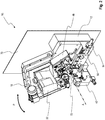
- FIG. 1 an exploded view is shown which serves to illustrate the various configuration options of an embodiment of the device 10 according to the present invention.
- a massive base 12 with which the device in the later explained according to the first configuration according to FIG. 2 supported on a surface, not shown.
- the base 12 can form part of a machine base, which alternatively also of a holding plate 70 (see FIG. 2 ) may be formed alone or in addition to the base 12.
- a holding plate 70 see FIG. 2
- the base 12 has a base bearing eye 16, through the center of which a bearing axis A extends.
- a bearing module 18 in various configurations attachable, which will be discussed in more detail below. This is the central aspect of the present invention.
- the bearing module 18 has a bearing eye 20, which is aligned as it were with the bearing axis A, wherein the bearing axis A passes through the center of the bearing eye 20.
- the storage module 18 will be described in more detail below with reference to the FIGS. 4 to 9 described.
- a processing unit 22 is mounted, which can be variably equipped. So is in the presentation according to FIG. 1 on the processing unit 22, a grinding head 24 attachable, which can be driven either via a drive motor 26 or a drive motor 28 and a drive train 30.
- the processing unit 22 is used in a conventional manner for processing Zahnbrust- or tooth back.
- FIG. 1 a further processing unit 32 is shown, which has two parallel drive spindles 34, 36, to which two opposing grinding wheels or Eoderierusionn can be attached.
- This processing unit 32 can be attached to the storage module 18 as an alternative to the processing unit 22.
- the processing unit 32 serves the per se known flank processing of individual teeth.
- FIG. 1 individual components of a workpiece receiving device, which is formed with alternatively usable clamping devices 42, 43, 44, which can be attached depending on the machine configuration optionally on the storage module 18 by means of a mounting plate 46 or on the spacer 14.
- the clamping devices 42, 43, 44 are each used to clamp a workpiece to be machined (not shown), in the example a circular saw blade (not shown), after positioning in a desired position for processing with the processing unit 22 and 32 respectively.
- the clamping devices 42, 43, 44 can be coupled with a feed device 48.
- the feed device 48 serves to move the workpiece to be machined step by step, for example tooth by tooth, into a processing position, where it is then clamped.
- the feed device 48 can be optionally two alternative pawls 54, 56 assign, which can be coupled depending on the saw blade used with the feed device 48.
- the component 60 is used to adjust the grinding spindle of the grinding head 24. If such adjustment is not required, the component 60 is replaced by a simple cover 58.
- a Einfahrschlitten 52 is further mounted, with which the device 10 can be adjusted to different workpiece sizes, for example, different saw blades of different diameters.
- an insertion carriage 50 is provided, which can be mounted on the spacer 14. It should be noted with regard to the swivel plate 47 that it can be attached pivotably to the bearing eye 20 in the second machine configuration, which will be explained in detail below.
- FIG. 1 On the right side of the base 12 can be seen also a pivoting unit 62, depending on the following in more detail with reference to Figures 2 and 3 explained respective machine configuration for pivoting various machine components is used.
- FIG. 1 An exploded view shows an overview of how with the present invention, as required, a device 10 can be adapted to specific processing requirements. This will now be discussed in detail.
- FIG. 2 shows a first configuration of the device 10 1 according to the invention.
- the base 12 is fixedly connected via a retaining plate 70 with a substrate, not shown.
- the base 12 and the retaining plate 70 form the machine base, so to speak.
- At the base 12 of the spacer 14 is attached. This carries the Einfahrschlitten 50.
- the feed device 48 is attached to the spacer 14. Fixedly coupled to the machine base 12 is also the clamping device 42.
- the storage module 18 with the attached processing unit 22 via the bearing eye 20 (in FIG. 2 concealed) about the bearing axis A according to the double arrow P is pivotable in order to align a grinding wheel 72 of the processing unit 22, for example, relative to a respective cutting tooth to be machined a circular saw blade, not shown.
- the grinding wheel 72 serves, for example, for processing the tooth face or the tooth back of individual teeth and dips into a space between the teeth of the saw blade for processing.
- the processing unit 22 can be displaced relative to the storage module 18 via a concealed slide arrangement. This will be described below with reference to the FIGS. 4 to 9 explained.
- the processing unit 32 (see FIG. 1 ) for machining the tooth flanks.
- the bearing module 18 is pivotable about the bearing axis A. This pivoting is achieved in that the bearing eye 20 is pivotally mounted on the base bearing eye 16 and can be pivoted about the pivoting device 62 in a controlled manner.
- FIG. 3 shows one too FIG. 2 Alternative embodiment of the device 10 2 according to the invention.
- the bearing module 18 is attached via a circumferential housing flange 80 by means of fastening bolts 82 fixed to the support plate 70 of the machine base.
- the pivot unit 62 is provided on the back of the holding plate 70.
- the base 12 is not required in this second configuration of the device according to the invention.
- the storage module 18 is fixedly secured to the retaining tongue 70 of the machine base.
- the storage module 18 is thus - in contrast to the embodiment according to FIG. 2 - not swiveling.
- the processing unit 22 is mounted displaceably on the storage module 18 via a concealed slide arrangement. Alternatively, in turn, the processing unit 32 can be used.
- the clamping unit 43 is also attached to the mounting plate 46.
- FIG. 3 the workpiece to be machined about the bearing axis A pivotable. This is achieved by the fact that in FIG. 1 shown mounting plate 46 and attached thereto components feed device 48, clamping unit 43 and Einfahrschlitten 52 by means of the pivoting unit 62 via the pivot plate 47 about the bearing axis A are pivotable as needed. This is achieved by using the bearing eye 20 as a bearing for the further components bearing pivot plate 47.
- the two machine configurations 10 1 and 10 2 according to FIG. 2 and FIG. 3 So have essentially the same components, but differ in how the storage module 18 is used.
- This may be pivotally mounted on the machine base 12, 70 as in the configuration of FIG. 2 or fixedly attached to the machine base support plate 70 as in the configuration of FIG. 3 ,
- the bearing eye 20 serves as a bearing for the pivoting of the bearing module 18 itself relative to the machine base 12,70 or as a bearing for pivoting the pivot plate 47, which carries the other components Einfahrschlitten 52, feed device 48 and clamping unit 43 pivotable.
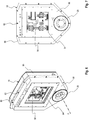
- FIG. 4 shows an arrangement, as in the configuration according to FIG. 3 is used, ie an arrangement in which the bearing eye 20, the components Feed device, clamping unit and retracting carriage of the workpiece holder are rotatable, wherein the bearing module 18 itself is fixed on the bolt 82 on the machine base (not shown).
- the processing unit 22 can be displaced along the axes X, Z via a cross slide arrangement arranged within the bearing module 18 with mutually perpendicular guide rails 90, 92.
- This cross slide arrangement with the guide rails 90, 92 is accessible via a window 94, which is provided in the housing 96 of the bearing module 18.
- a window can be the processing units 22 and 32 attach to the cross slide assembly.
- the housing 96 is formed like a box and terminates rounded down, wherein it receives the bearing eye 20 in a lower substantially triangular area 98.
Landscapes
- Engineering & Computer Science (AREA)
- Mechanical Engineering (AREA)
- Finish Polishing, Edge Sharpening, And Grinding By Specific Grinding Devices (AREA)
- Constituent Portions Of Griding Lathes, Driving, Sensing And Control (AREA)
Claims (11)
- Dispositif (10) à configuration variable destiné à l'aiguisement de lames de scie, comprenant :- une base de machine (12, 70) pour installer le dispositif (10) sur une surface,- un module de support (18) doté d'un point d'appui (20), qui peut être monté sur la base de machine (12, 70),- une unité d'usinage (22, 32) susceptible d'être montée sur la base de machine (12, 70) par l'intermédiaire du module de support (18) et- un dispositif de réception de pièce destiné à recevoir les pièces à usiner,caractérisé en ce que le point d'appui (20) du module de support (18) est conçu pour, au choix,- monter le module de support (18) sur la base de machine (12, 70) de manière pivotante par rapport à la base de machine (12, 70) autour du point d'appui (20) dans une première configuration du dispositif (101), et- recevoir le dispositif de réception de pièce de manière pivotante par rapport au module de support (18) dans une deuxième configuration du dispositif (102), dans laquelle le module de support (18) est rendu solidaire de la base de machine (70).
- Dispositif (10) selon la revendication 1,
caractérisé en ce que le point d'appui comporte un oeil de support (20) ayant un axe de support (A) qui est prévu comme axe de pivotement pour le module de support (18) dans la première configuration du dispositif (101) et comme axe de pivotement (A) pour le dispositif de réception de pièce dans la deuxième configuration du dispositif (102). - Dispositif (10) selon la revendication 1 ou 2,
caractérisé en ce que le module de support (18) comporte un carter (96) avec une bride de carter (80) qui est prévue pour être montée sur la base de machine (70) dans la deuxième configuration du dispositif (10). - Dispositif (10) selon l'une des revendications précédentes,
caractérisé en ce que l'unité d'usinage (22, 32) est montée mobile sur le module de support (18), de préférence par l'intermédiaire d'un ensemble formant chariot multiaxe. - Dispositif (10) selon l'une des revendications précédentes,
caractérisé en ce que l'unité d'usinage (22, 32) comprend au moins une broche d'usinage entraînée en rotation. - Dispositif (10) selon l'une des revendications précédentes,
caractérisé en ce qu'au moins un dispositif de serrage (42, 43, 44) peut être associé au dispositif de réception de pièce, la pièce à usiner pouvant être reçue à l'aide dudit dispositif de serrage. - Dispositif (10) selon l'une des revendications précédentes,
caractérisé en ce qu'au moins un dispositif d'avance (48) peut être associé au dispositif de réception de pièce, la pièce à usiner pouvant être déplacée progressivement à l'aide dudit dispositif d'avance pour l'usinage de dents individuelles, de préférence dans le cas d'une lame de scie circulaire comportant une pluralité de dents de coupe. - Dispositif (10) selon l'une des revendications précédentes,
caractérisé en ce que le dispositif de réception de pièce comporte un dispositif de chariot pour l'adaptation à différentes tailles de pièces. - Dispositif (10) selon l'une des revendications précédentes,
caractérisé en ce que le dispositif de réception de pièce est couplé solidement à la base de machine (12, 70) dans la première configuration du dispositif (101). - Dispositif (10) selon l'une des revendications précédentes,
caractérisé en ce qu'au moins une unité de pivotement (62) est prévue sur la base de machine (12, 70) pour faire pivoter le module de support (18) autour de l'axe de support (A) dans la première configuration du dispositif (101), et pour faire pivoter le dispositif de réception de pièce autour de l'axe de support (A) dans la deuxième configuration du dispositif (102). - Dispositif (10) selon l'une des revendications précédentes,
caractérisé en ce que l'unité d'usinage (22, 32) présente au moins un disque abrasif ou un disque d'érosion.
Priority Applications (1)
| Application Number | Priority Date | Filing Date | Title |
|---|---|---|---|
| PL14180920T PL2848347T3 (pl) | 2013-09-11 | 2014-08-14 | Urządzenie o zmiennej konfiguracji do obróbki ostrzącej brzeszczotów pił |
Applications Claiming Priority (1)
| Application Number | Priority Date | Filing Date | Title |
|---|---|---|---|
| DE102013015177.5A DE102013015177A1 (de) | 2013-09-11 | 2013-09-11 | Vorrichtung mit variabler Konfiguration zum Bearbeiten von Werkstücken, insbesondere zum Schärfbearbeiten von Sägeblättern |
Publications (2)
| Publication Number | Publication Date |
|---|---|
| EP2848347A1 EP2848347A1 (fr) | 2015-03-18 |
| EP2848347B1 true EP2848347B1 (fr) | 2017-11-29 |
Family
ID=51357760
Family Applications (1)
| Application Number | Title | Priority Date | Filing Date |
|---|---|---|---|
| EP14180920.2A Active EP2848347B1 (fr) | 2013-09-11 | 2014-08-14 | Dispositif présentant une configuration variable destiné à l'aiguisement de lames de scie |
Country Status (4)
| Country | Link |
|---|---|
| EP (1) | EP2848347B1 (fr) |
| CN (1) | CN104416230B (fr) |
| DE (1) | DE102013015177A1 (fr) |
| PL (1) | PL2848347T3 (fr) |
Families Citing this family (1)
| Publication number | Priority date | Publication date | Assignee | Title |
|---|---|---|---|---|
| CN106808020A (zh) * | 2015-11-30 | 2017-06-09 | 湖南衡泰机械科技有限公司 | Cnc锯片齿距定位装置 |
Citations (1)
| Publication number | Priority date | Publication date | Assignee | Title |
|---|---|---|---|---|
| DE19743528C1 (de) * | 1997-10-01 | 1999-07-29 | Vollmer Werke Maschf | Meßeinrichtung an einer Maschine zum Bearbeiten von Werkstücken mit Schneidzähnen, insbes. von Sägeblättern |
Family Cites Families (6)
| Publication number | Priority date | Publication date | Assignee | Title |
|---|---|---|---|---|
| US2052600A (en) * | 1933-04-20 | 1936-09-01 | Edward C Boss | Machine construction |
| DE4413483A1 (de) * | 1994-04-19 | 1995-10-26 | Hph Werkzeugschleiftechn Gmbh | Aufsatzgerät für eine Werkzeugschleifmaschine |
| US6178856B1 (en) * | 1995-02-22 | 2001-01-30 | Robert John Caddaye | Lathes |
| US6637302B2 (en) * | 2001-03-22 | 2003-10-28 | Toshiharu Tom Miyano | Machining system and method of machining a workpiece using the machining system |
| CN201231354Y (zh) * | 2008-06-23 | 2009-05-06 | 虞荣江 | 新型电动锯片磨齿机 |
| CN101791725B (zh) * | 2009-12-25 | 2011-09-14 | 长沙哈量凯帅精密机械有限公司 | 弧齿锥齿轮和准双曲面齿轮成形法大轮磨齿机 |
-
2013
- 2013-09-11 DE DE102013015177.5A patent/DE102013015177A1/de not_active Withdrawn
-
2014
- 2014-08-14 PL PL14180920T patent/PL2848347T3/pl unknown
- 2014-08-14 EP EP14180920.2A patent/EP2848347B1/fr active Active
- 2014-09-10 CN CN201410458786.1A patent/CN104416230B/zh active Active
Patent Citations (1)
| Publication number | Priority date | Publication date | Assignee | Title |
|---|---|---|---|---|
| DE19743528C1 (de) * | 1997-10-01 | 1999-07-29 | Vollmer Werke Maschf | Meßeinrichtung an einer Maschine zum Bearbeiten von Werkstücken mit Schneidzähnen, insbes. von Sägeblättern |
Also Published As
| Publication number | Publication date |
|---|---|
| PL2848347T3 (pl) | 2018-03-30 |
| CN104416230A (zh) | 2015-03-18 |
| DE102013015177A1 (de) | 2015-03-12 |
| EP2848347A1 (fr) | 2015-03-18 |
| CN104416230B (zh) | 2018-03-30 |
Similar Documents
| Publication | Publication Date | Title |
|---|---|---|
| EP2161092B1 (fr) | Machine à meuler des roues dentées et procédé de dressage d'un outil de meulage | |
| EP2855082B1 (fr) | Dispositif pour aiguiser des outils à taillants comme, par exemple, des forets, fraises ou similaire | |
| EP1487608B1 (fr) | Nez de broche pour fraiseuse universelle | |
| EP1745877A1 (fr) | Machine de taillage de roues dentées, notamment machine de taillage de roues dentées coniques, avec un dispositif pour la chanfreiner et l' ébavurer des extrémités de dents des roues dentées | |
| DE102015102899B4 (de) | Fräsvorrichtung für die Brillenglasfertigung mit zwei Frässtationen | |
| EP2301712A1 (fr) | Machine-outil et support de pièce à usiner | |
| DE202007002442U1 (de) | Drehbarer angetriebener Servo-Werkzeugsupport | |
| DE102008016497A1 (de) | Bearbeitungskopf | |
| WO2010081712A1 (fr) | Machine d'usinage | |
| DE202018102298U1 (de) | Vorrichtung zum schleifenden Bearbeiten von Zahnrad-Werkstücken | |
| EP1648655A1 (fr) | Support multifonctions comportant deux axes de pivotement paralleles | |
| DE10116994A1 (de) | Werkzeugmaschine | |
| EP3291943B1 (fr) | Machine-outil | |
| EP3288697A1 (fr) | Installation d'usinage pour éléments structuraux d'avions | |
| DE102009004337B3 (de) | Verfahren und Vorrichtung zur spanenden Bearbeitung eines um eine Mittelachse rotierenden Werkstücks | |
| DE2044429C3 (de) | Zusatzeinrichtung für das Bearbeiten von Kugel-Innenflächen auf einer Vertikaldrehmaschine | |
| EP2848347B1 (fr) | Dispositif présentant une configuration variable destiné à l'aiguisement de lames de scie | |
| EP2161099B1 (fr) | Affûteuse | |
| DE102016109036A1 (de) | Werkzeugschwenkaggregat für eine Drehmaschine | |
| DE102006047343B3 (de) | Schleifmaschine | |
| DE102004031584B4 (de) | Schärfmaschine zum Scharfschleifen von Klingen | |
| EP2703119B1 (fr) | Machine de traitement | |
| DE2505397C2 (de) | Vorrichtung zum spanabhebenden Bearbeiten der Zahnenden von Zahnrädern | |
| EP2305418A1 (fr) | Agencement de tête basculante à plusieurs axes pour une machine de traitement | |
| EP2371482A1 (fr) | Machine-outil |
Legal Events
| Date | Code | Title | Description |
|---|---|---|---|
| PUAI | Public reference made under article 153(3) epc to a published international application that has entered the european phase |
Free format text: ORIGINAL CODE: 0009012 |
|
| 17P | Request for examination filed |
Effective date: 20140814 |
|
| AK | Designated contracting states |
Kind code of ref document: A1 Designated state(s): AL AT BE BG CH CY CZ DE DK EE ES FI FR GB GR HR HU IE IS IT LI LT LU LV MC MK MT NL NO PL PT RO RS SE SI SK SM TR |
|
| AX | Request for extension of the european patent |
Extension state: BA ME |
|
| R17P | Request for examination filed (corrected) |
Effective date: 20150727 |
|
| RBV | Designated contracting states (corrected) |
Designated state(s): AL AT BE BG CH CY CZ DE DK EE ES FI FR GB GR HR HU IE IS IT LI LT LU LV MC MK MT NL NO PL PT RO RS SE SI SK SM TR |
|
| STAA | Information on the status of an ep patent application or granted ep patent |
Free format text: STATUS: EXAMINATION IS IN PROGRESS |
|
| 17Q | First examination report despatched |
Effective date: 20161223 |
|
| GRAP | Despatch of communication of intention to grant a patent |
Free format text: ORIGINAL CODE: EPIDOSNIGR1 |
|
| STAA | Information on the status of an ep patent application or granted ep patent |
Free format text: STATUS: GRANT OF PATENT IS INTENDED |
|
| INTG | Intention to grant announced |
Effective date: 20170725 |
|
| GRAS | Grant fee paid |
Free format text: ORIGINAL CODE: EPIDOSNIGR3 |
|
| GRAA | (expected) grant |
Free format text: ORIGINAL CODE: 0009210 |
|
| STAA | Information on the status of an ep patent application or granted ep patent |
Free format text: STATUS: THE PATENT HAS BEEN GRANTED |
|
| AK | Designated contracting states |
Kind code of ref document: B1 Designated state(s): AL AT BE BG CH CY CZ DE DK EE ES FI FR GB GR HR HU IE IS IT LI LT LU LV MC MK MT NL NO PL PT RO RS SE SI SK SM TR |
|
| REG | Reference to a national code |
Ref country code: CH Ref legal event code: EP |
|
| REG | Reference to a national code |
Ref country code: AT Ref legal event code: REF Ref document number: 949938 Country of ref document: AT Kind code of ref document: T Effective date: 20171215 |
|
| REG | Reference to a national code |
Ref country code: IE Ref legal event code: FG4D Free format text: LANGUAGE OF EP DOCUMENT: GERMAN |
|
| REG | Reference to a national code |
Ref country code: DE Ref legal event code: R096 Ref document number: 502014006383 Country of ref document: DE |
|
| REG | Reference to a national code |
Ref country code: NL Ref legal event code: MP Effective date: 20171129 |
|
| REG | Reference to a national code |
Ref country code: LT Ref legal event code: MG4D |
|
| PG25 | Lapsed in a contracting state [announced via postgrant information from national office to epo] |
Ref country code: LT Free format text: LAPSE BECAUSE OF FAILURE TO SUBMIT A TRANSLATION OF THE DESCRIPTION OR TO PAY THE FEE WITHIN THE PRESCRIBED TIME-LIMIT Effective date: 20171129 Ref country code: ES Free format text: LAPSE BECAUSE OF FAILURE TO SUBMIT A TRANSLATION OF THE DESCRIPTION OR TO PAY THE FEE WITHIN THE PRESCRIBED TIME-LIMIT Effective date: 20171129 Ref country code: SE Free format text: LAPSE BECAUSE OF FAILURE TO SUBMIT A TRANSLATION OF THE DESCRIPTION OR TO PAY THE FEE WITHIN THE PRESCRIBED TIME-LIMIT Effective date: 20171129 Ref country code: FI Free format text: LAPSE BECAUSE OF FAILURE TO SUBMIT A TRANSLATION OF THE DESCRIPTION OR TO PAY THE FEE WITHIN THE PRESCRIBED TIME-LIMIT Effective date: 20171129 Ref country code: NO Free format text: LAPSE BECAUSE OF FAILURE TO SUBMIT A TRANSLATION OF THE DESCRIPTION OR TO PAY THE FEE WITHIN THE PRESCRIBED TIME-LIMIT Effective date: 20180228 |
|
| PG25 | Lapsed in a contracting state [announced via postgrant information from national office to epo] |
Ref country code: RS Free format text: LAPSE BECAUSE OF FAILURE TO SUBMIT A TRANSLATION OF THE DESCRIPTION OR TO PAY THE FEE WITHIN THE PRESCRIBED TIME-LIMIT Effective date: 20171129 Ref country code: GR Free format text: LAPSE BECAUSE OF FAILURE TO SUBMIT A TRANSLATION OF THE DESCRIPTION OR TO PAY THE FEE WITHIN THE PRESCRIBED TIME-LIMIT Effective date: 20180301 Ref country code: BG Free format text: LAPSE BECAUSE OF FAILURE TO SUBMIT A TRANSLATION OF THE DESCRIPTION OR TO PAY THE FEE WITHIN THE PRESCRIBED TIME-LIMIT Effective date: 20180228 Ref country code: LV Free format text: LAPSE BECAUSE OF FAILURE TO SUBMIT A TRANSLATION OF THE DESCRIPTION OR TO PAY THE FEE WITHIN THE PRESCRIBED TIME-LIMIT Effective date: 20171129 Ref country code: HR Free format text: LAPSE BECAUSE OF FAILURE TO SUBMIT A TRANSLATION OF THE DESCRIPTION OR TO PAY THE FEE WITHIN THE PRESCRIBED TIME-LIMIT Effective date: 20171129 |
|
| PG25 | Lapsed in a contracting state [announced via postgrant information from national office to epo] |
Ref country code: NL Free format text: LAPSE BECAUSE OF FAILURE TO SUBMIT A TRANSLATION OF THE DESCRIPTION OR TO PAY THE FEE WITHIN THE PRESCRIBED TIME-LIMIT Effective date: 20171129 |
|
| PG25 | Lapsed in a contracting state [announced via postgrant information from national office to epo] |
Ref country code: CY Free format text: LAPSE BECAUSE OF FAILURE TO SUBMIT A TRANSLATION OF THE DESCRIPTION OR TO PAY THE FEE WITHIN THE PRESCRIBED TIME-LIMIT Effective date: 20171129 Ref country code: EE Free format text: LAPSE BECAUSE OF FAILURE TO SUBMIT A TRANSLATION OF THE DESCRIPTION OR TO PAY THE FEE WITHIN THE PRESCRIBED TIME-LIMIT Effective date: 20171129 Ref country code: SK Free format text: LAPSE BECAUSE OF FAILURE TO SUBMIT A TRANSLATION OF THE DESCRIPTION OR TO PAY THE FEE WITHIN THE PRESCRIBED TIME-LIMIT Effective date: 20171129 Ref country code: DK Free format text: LAPSE BECAUSE OF FAILURE TO SUBMIT A TRANSLATION OF THE DESCRIPTION OR TO PAY THE FEE WITHIN THE PRESCRIBED TIME-LIMIT Effective date: 20171129 Ref country code: CZ Free format text: LAPSE BECAUSE OF FAILURE TO SUBMIT A TRANSLATION OF THE DESCRIPTION OR TO PAY THE FEE WITHIN THE PRESCRIBED TIME-LIMIT Effective date: 20171129 |
|
| REG | Reference to a national code |
Ref country code: FR Ref legal event code: PLFP Year of fee payment: 5 |
|
| REG | Reference to a national code |
Ref country code: DE Ref legal event code: R097 Ref document number: 502014006383 Country of ref document: DE |
|
| PG25 | Lapsed in a contracting state [announced via postgrant information from national office to epo] |
Ref country code: SM Free format text: LAPSE BECAUSE OF FAILURE TO SUBMIT A TRANSLATION OF THE DESCRIPTION OR TO PAY THE FEE WITHIN THE PRESCRIBED TIME-LIMIT Effective date: 20171129 Ref country code: IT Free format text: LAPSE BECAUSE OF FAILURE TO SUBMIT A TRANSLATION OF THE DESCRIPTION OR TO PAY THE FEE WITHIN THE PRESCRIBED TIME-LIMIT Effective date: 20171129 Ref country code: RO Free format text: LAPSE BECAUSE OF FAILURE TO SUBMIT A TRANSLATION OF THE DESCRIPTION OR TO PAY THE FEE WITHIN THE PRESCRIBED TIME-LIMIT Effective date: 20171129 |
|
| PG25 | Lapsed in a contracting state [announced via postgrant information from national office to epo] |
Ref country code: MT Free format text: LAPSE BECAUSE OF FAILURE TO SUBMIT A TRANSLATION OF THE DESCRIPTION OR TO PAY THE FEE WITHIN THE PRESCRIBED TIME-LIMIT Effective date: 20171129 |
|
| PLBE | No opposition filed within time limit |
Free format text: ORIGINAL CODE: 0009261 |
|
| STAA | Information on the status of an ep patent application or granted ep patent |
Free format text: STATUS: NO OPPOSITION FILED WITHIN TIME LIMIT |
|
| 26N | No opposition filed |
Effective date: 20180830 |
|
| PG25 | Lapsed in a contracting state [announced via postgrant information from national office to epo] |
Ref country code: SI Free format text: LAPSE BECAUSE OF FAILURE TO SUBMIT A TRANSLATION OF THE DESCRIPTION OR TO PAY THE FEE WITHIN THE PRESCRIBED TIME-LIMIT Effective date: 20171129 |
|
| PG25 | Lapsed in a contracting state [announced via postgrant information from national office to epo] |
Ref country code: MC Free format text: LAPSE BECAUSE OF FAILURE TO SUBMIT A TRANSLATION OF THE DESCRIPTION OR TO PAY THE FEE WITHIN THE PRESCRIBED TIME-LIMIT Effective date: 20171129 |
|
| REG | Reference to a national code |
Ref country code: CH Ref legal event code: PL |
|
| GBPC | Gb: european patent ceased through non-payment of renewal fee |
Effective date: 20180814 |
|
| PG25 | Lapsed in a contracting state [announced via postgrant information from national office to epo] |
Ref country code: LU Free format text: LAPSE BECAUSE OF NON-PAYMENT OF DUE FEES Effective date: 20180814 Ref country code: CH Free format text: LAPSE BECAUSE OF NON-PAYMENT OF DUE FEES Effective date: 20180831 Ref country code: LI Free format text: LAPSE BECAUSE OF NON-PAYMENT OF DUE FEES Effective date: 20180831 |
|
| REG | Reference to a national code |
Ref country code: BE Ref legal event code: MM Effective date: 20180831 |
|
| REG | Reference to a national code |
Ref country code: IE Ref legal event code: MM4A |
|
| PG25 | Lapsed in a contracting state [announced via postgrant information from national office to epo] |
Ref country code: IE Free format text: LAPSE BECAUSE OF NON-PAYMENT OF DUE FEES Effective date: 20180814 |
|
| PG25 | Lapsed in a contracting state [announced via postgrant information from national office to epo] |
Ref country code: BE Free format text: LAPSE BECAUSE OF NON-PAYMENT OF DUE FEES Effective date: 20180831 |
|
| PG25 | Lapsed in a contracting state [announced via postgrant information from national office to epo] |
Ref country code: GB Free format text: LAPSE BECAUSE OF NON-PAYMENT OF DUE FEES Effective date: 20180814 |
|
| PG25 | Lapsed in a contracting state [announced via postgrant information from national office to epo] |
Ref country code: PT Free format text: LAPSE BECAUSE OF FAILURE TO SUBMIT A TRANSLATION OF THE DESCRIPTION OR TO PAY THE FEE WITHIN THE PRESCRIBED TIME-LIMIT Effective date: 20171129 Ref country code: HU Free format text: LAPSE BECAUSE OF FAILURE TO SUBMIT A TRANSLATION OF THE DESCRIPTION OR TO PAY THE FEE WITHIN THE PRESCRIBED TIME-LIMIT; INVALID AB INITIO Effective date: 20140814 |
|
| PG25 | Lapsed in a contracting state [announced via postgrant information from national office to epo] |
Ref country code: MK Free format text: LAPSE BECAUSE OF NON-PAYMENT OF DUE FEES Effective date: 20171129 |
|
| PG25 | Lapsed in a contracting state [announced via postgrant information from national office to epo] |
Ref country code: AL Free format text: LAPSE BECAUSE OF FAILURE TO SUBMIT A TRANSLATION OF THE DESCRIPTION OR TO PAY THE FEE WITHIN THE PRESCRIBED TIME-LIMIT Effective date: 20171129 Ref country code: IS Free format text: LAPSE BECAUSE OF FAILURE TO SUBMIT A TRANSLATION OF THE DESCRIPTION OR TO PAY THE FEE WITHIN THE PRESCRIBED TIME-LIMIT Effective date: 20180329 |
|
| REG | Reference to a national code |
Ref country code: AT Ref legal event code: MM01 Ref document number: 949938 Country of ref document: AT Kind code of ref document: T Effective date: 20190814 |
|
| PG25 | Lapsed in a contracting state [announced via postgrant information from national office to epo] |
Ref country code: AT Free format text: LAPSE BECAUSE OF NON-PAYMENT OF DUE FEES Effective date: 20190814 |
|
| REG | Reference to a national code |
Ref country code: DE Ref legal event code: R082 Ref document number: 502014006383 Country of ref document: DE Representative=s name: THUM, MOETSCH, WEICKERT PATENTANWAELTE PARTG M, DE Ref country code: DE Ref legal event code: R082 Ref document number: 502014006383 Country of ref document: DE Representative=s name: THUM & PARTNER THUM MOETSCH WEICKERT PATENTANW, DE |
|
| P01 | Opt-out of the competence of the unified patent court (upc) registered |
Effective date: 20230523 |
|
| PGFP | Annual fee paid to national office [announced via postgrant information from national office to epo] |
Ref country code: TR Payment date: 20230809 Year of fee payment: 10 |
|
| PGFP | Annual fee paid to national office [announced via postgrant information from national office to epo] |
Ref country code: PL Payment date: 20230804 Year of fee payment: 10 Ref country code: FR Payment date: 20230821 Year of fee payment: 10 Ref country code: DE Payment date: 20230822 Year of fee payment: 10 |