EP2848331B1 - Method for making a reclosable cap - Google Patents
Method for making a reclosable cap Download PDFInfo
- Publication number
- EP2848331B1 EP2848331B1 EP13183964.9A EP13183964A EP2848331B1 EP 2848331 B1 EP2848331 B1 EP 2848331B1 EP 13183964 A EP13183964 A EP 13183964A EP 2848331 B1 EP2848331 B1 EP 2848331B1
- Authority
- EP
- European Patent Office
- Prior art keywords
- reclosable
- cap
- score
- metal
- coating
- Prior art date
- Legal status (The legal status is an assumption and is not a legal conclusion. Google has not performed a legal analysis and makes no representation as to the accuracy of the status listed.)
- Active
Links
- 238000000034 method Methods 0.000 title claims description 36
- 229910052751 metal Inorganic materials 0.000 claims description 66
- 239000002184 metal Substances 0.000 claims description 66
- 238000000576 coating method Methods 0.000 claims description 30
- 239000011248 coating agent Substances 0.000 claims description 28
- 239000004922 lacquer Substances 0.000 claims description 10
- 238000005520 cutting process Methods 0.000 claims description 7
- 238000009740 moulding (composite fabrication) Methods 0.000 claims description 6
- 238000004519 manufacturing process Methods 0.000 description 7
- 239000010410 layer Substances 0.000 description 6
- 239000011247 coating layer Substances 0.000 description 5
- 239000000463 material Substances 0.000 description 5
- 229920000728 polyester Polymers 0.000 description 4
- 239000000203 mixture Substances 0.000 description 3
- 229920003023 plastic Polymers 0.000 description 3
- 239000004033 plastic Substances 0.000 description 3
- 238000003860 storage Methods 0.000 description 3
- NIXOWILDQLNWCW-UHFFFAOYSA-N acrylic acid group Chemical group C(C=C)(=O)O NIXOWILDQLNWCW-UHFFFAOYSA-N 0.000 description 2
- 238000005260 corrosion Methods 0.000 description 2
- 230000007797 corrosion Effects 0.000 description 2
- 230000001419 dependent effect Effects 0.000 description 2
- 238000010586 diagram Methods 0.000 description 2
- 239000000126 substance Substances 0.000 description 2
- 229910000838 Al alloy Inorganic materials 0.000 description 1
- 229910000851 Alloy steel Inorganic materials 0.000 description 1
- 229910000831 Steel Inorganic materials 0.000 description 1
- 229910052782 aluminium Inorganic materials 0.000 description 1
- XAGFODPZIPBFFR-UHFFFAOYSA-N aluminium Chemical compound [Al] XAGFODPZIPBFFR-UHFFFAOYSA-N 0.000 description 1
- 230000015572 biosynthetic process Effects 0.000 description 1
- 150000001875 compounds Chemical class 0.000 description 1
- 239000011521 glass Substances 0.000 description 1
- 239000000976 ink Substances 0.000 description 1
- 239000010814 metallic waste Substances 0.000 description 1
- 239000010959 steel Substances 0.000 description 1
- 239000005028 tinplate Substances 0.000 description 1
Images

Classifications
-
- B—PERFORMING OPERATIONS; TRANSPORTING
- B21—MECHANICAL METAL-WORKING WITHOUT ESSENTIALLY REMOVING MATERIAL; PUNCHING METAL
- B21D—WORKING OR PROCESSING OF SHEET METAL OR METAL TUBES, RODS OR PROFILES WITHOUT ESSENTIALLY REMOVING MATERIAL; PUNCHING METAL
- B21D51/00—Making hollow objects
- B21D51/16—Making hollow objects characterised by the use of the objects
- B21D51/38—Making inlet or outlet arrangements of cans, tins, baths, bottles, or other vessels; Making can ends; Making closures
- B21D51/44—Making closures, e.g. caps
- B21D51/443—Making closures, e.g. caps easily removable closures, e.g. by means of tear strips
-
- B—PERFORMING OPERATIONS; TRANSPORTING
- B21—MECHANICAL METAL-WORKING WITHOUT ESSENTIALLY REMOVING MATERIAL; PUNCHING METAL
- B21D—WORKING OR PROCESSING OF SHEET METAL OR METAL TUBES, RODS OR PROFILES WITHOUT ESSENTIALLY REMOVING MATERIAL; PUNCHING METAL
- B21D51/00—Making hollow objects
- B21D51/16—Making hollow objects characterised by the use of the objects
- B21D51/38—Making inlet or outlet arrangements of cans, tins, baths, bottles, or other vessels; Making can ends; Making closures
- B21D51/44—Making closures, e.g. caps
- B21D51/50—Making screw caps
-
- B—PERFORMING OPERATIONS; TRANSPORTING
- B65—CONVEYING; PACKING; STORING; HANDLING THIN OR FILAMENTARY MATERIAL
- B65D—CONTAINERS FOR STORAGE OR TRANSPORT OF ARTICLES OR MATERIALS, e.g. BAGS, BARRELS, BOTTLES, BOXES, CANS, CARTONS, CRATES, DRUMS, JARS, TANKS, HOPPERS, FORWARDING CONTAINERS; ACCESSORIES, CLOSURES, OR FITTINGS THEREFOR; PACKAGING ELEMENTS; PACKAGES
- B65D5/00—Rigid or semi-rigid containers of polygonal cross-section, e.g. boxes, cartons or trays, formed by folding or erecting one or more blanks made of paper
- B65D5/42—Details of containers or of foldable or erectable container blanks
- B65D5/56—Linings or internal coatings, e.g. pre-formed trays provided with a blow- or thermoformed layer
Definitions
- the present invention relates to a method for making a reclosable cap.
- a reclosable cap such as a reclosable cap reclosable by screwing, also known as a screw cap or twist off cap, is generally used as a closure for a container especially a glass bottle or jar, onto which the reclosable cap is applied, such as by screwing or otherwise.
- the reclosable cap is tightly applied on to the container.
- a subatmospheric pressure such as a vacuum.
- Such atmospheric pressure is generally created when the container is hot filled, subsequently closed off with the reclosable cap, and the content cooled.
- the container Due to the internal subatmospheric pressure, the container is relatively difficult to open and a relatively high force is to be applied by the consumer either manually or using a tool for removing the reclosable cap, such as by screwing off the screw cap.
- DE-A-4240373 discloses a method for making reclosable caps.
- a screw cap may be provided with a score forming a weakened section in the screw cap.
- the score is generally designed such, that by breaking the score manually an open communication is formed with the interior of the container and the vacuum released. Thereby the removal of the screw cap requires less force.
- the formation of the score in the metal reclosable cap requires that after scoring the score is to be coated in order to avoid corrosion and/or metal contact with the content of the container.
- the making of such reclosable cap is difficult, requires specific scoring operations, and is carried out at relatively low production speeds. Such low speed retards the production rate or requires additional parallel scoring operations.
- the present invention has for its object to improve the prior art method for making a reclosable cap, such that this method can be implemented in a standard cap producing process an apparatus, and provides flexibility in the production of various types of reclosable caps, independent of the type and speed of the scoring operation.
- the method according to the invention is based on the insight that by providing the metal part with the score at a location defined by the ultimate position in the reclosable cap, before the metal layer (or metal sheet) is coated the objects of the invention are substantially met and fulfilled. For reasons, that the scored metal layer, or scored metal sheet can be used in the traditional operations and apparatuses for making reclosable caps.
- the method for making the reclosable cap is independent of the ultimate reclosable cap to be made because the presence of the score in a surface does not interfere with the shape and general properties of the reclosable cap, and of the shells.
- the score is formed in the surface of the metal layer forming the outer side of the reclosable cap.
- the score is formed in the surface of the metal layer forming the inner side of the reclosable cap.
- any type of lacquer, coating, and/or printing, or the like may be used for covering the score formed in a metal surface and thereby avoiding exposure of the score. Because such score in the metal surface would be vulnerable to corrosion, and/or make undesired content, in particular food contact.
- lacquers, coatings, and printing are plastics, such as polyester, polyester-organosol systems, epoxyphenolic systems, acrylic systems, and epoxyanhydride systems.
- the lacquer or coating may comprise one or more coating layers, such as two or three coating layers of the same or different composition.
- the metal layer which forms a metal strip is cut into a metal sheet, which sheets are scored and then temporarily stored, such as in the form of a stack.
- the scored metal sheets are taken from the stack and may be fed in a substantially continuous manner into the coating step (ii) of the method.
- the cut and scored metal sheet to be coated in step (ii) originates from a stack of metal sheets.
- the increased flexibility of the method according to the invention allows for the use of a scoring operation which is carried out at a relatively low scoring speed.
- a scoring operation which is carried out at a relatively low scoring speed.
- An example would be a laser scoring operation, a hammer and anvil operation and/or chemical.
- the scoring is carried out at a relatively low speed, and the coating, cutting and forming of the reclosable cap is carried out at high speed.
- This overcomes the use of duplication or multiplication of low speed scoring operations in order to produce scored metal sheets at a speed which is comparable to the speed of the remainder method of making reclosable caps.
- the method may be implemented into a reclosable cap making method and apparatus functioning at any production speed.
- a reclosable cap directly obtained by the method according to the invention, the cap comprising a central panel, a circumferential skirt provided with reclosable means for reclosable attachment to the container or jar, such as a snapping edge or a screw thread, and a score provided in a central panel surface, wherein the score and the central panel surface are provided with a unitary coating, which may comprise one or more, such as two or three coating layers.
- a unitary or continuous coating or lacquer covering the score and the surface in which the score has been formed, shows that this reclosable cap has been produced with the method according to the invention.
- the central panel surface provided with the score forms the inner side of the reclosable cap and the outer side of the reclosable cap comprises a marking for the location of the score. Accordingly, the consumer is guided and alerted to press at a particular location in order to break the score which is not visible from the outside.
- reclosable cap directly obtained by the method according to the invention. But it will be evident that other types of reclosable caps, such as a reclosable by snapping, clamping, or the like. But preferred is a cap reclosable by screwing.
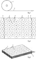
- Figure 1 shows a metal coil 1 which is decoiled providing a metal strip 2.
- the width of the metal strip is dependent on size and number of screw caps to be made and ranging generally from about 30cm to 150cm, such as 80 to 120cm.
- the thickness of the metal strip ranges generally from about 0.10mm to about 0.30mm, preferably from about0.14mm to about 0.25 mm, typically about 0.16 mm).
- the metal for the reclosable cap may be steel, a steel alloy, tin plate, aluminum, aluminum alloy, and mixtures thereof, as well as laminates of metal and a suitable plastic.
- the metal strip 2 is provided with scores 3 at locations defined by the ultimate position in the reclosable cap 15, of which the outer profile is illustrated by phantom circles 4. Rows 5 of scores 3 are at mutually offset locations such as to use maximum material from the metal strip 2 and avoid as much as possible metal waste.
- the metal strip 2 may be cut according to a scroll line 6 following again the offset positions of the rows 5 of scores 3.
- the cut metal sheets 7 provided with the scores 3 are stored in a stack 8. In the method according to the invention these cut and scored metal sheets 7 are introduced into a coating step for providing at least the scored side of the metal sheet with a coating 9.
- a suitable coating or lacquer material may be a plastic, such as polyester, polyester-organosol systems, epoxyphenolic systems, acrylic systems, and epoxyanhydride systems.
- the lacquer or coating may comprise one or more coating layers, such as two or three coating layers of the same or different composition.
- a printing coating may be used also for instance a polyester, conventional inks and top coat polyester, and further also conventional UV system. After coating, lacquering and/or printing, and cutting the metal layer 2, or metal sheet 7 into shells, the screw cap is formed in a traditional manner (not further described).
- FIG. 4 An example of a method for making a screw cap 15 not belonging to the invention is illustrated by the flow sheet of figure 4 .
- a metal strip 2 is fed in a continuous manner to a scoring unit 10, in which, as illustrated in figure 2 , the metal strip 2 is provided with scores 3 at locations defined by the ultimate position in the screw caps 15.
- the scoring operation may be carried out using a number of scoring units, of which the number could be equal to the scores to be provided by one or more rows 5, see figure 2 .
- Each such scoring unit 10 may comprise a laser scoring unit, or a hammer and anvil scoring unit, and/or chemical scoring unit. It is also possible to use a massive pair of rolls provided with projections for imprinting the scores 3 into the metal strip 2.
- the scored metal strip 11 is fed to a lack ring and/or printing unit 12. At least the side of the metal strip 11 provided with the scores 3, is provided with a lacquer or other type of coating. Particularly, when the score 3 is to be present at the inside of the screw cap, the other surface of the scored metal strip is provided with a coating or printing, comprising preferably directions or information for the location for the inside score 3.
- the coated/lacquered and/or printed metal strip 13 is then fed to a unit 14 for cutting shells and forming the screw cap 15.
- a preferred method for making a screw cap 24 according to the invention is illustrated in the flow sheet of figure 5 .
- the metal strip 2 is fed to a unit 16 for cutting the metal strip into metal sheets 17.
- the metal sheet 17 is subsequently carried to a storage unit 18 where the cut metal sheets 17 are stored in stacks 8.
- the metal sheets are fed to a unit 19 for scoring the metal sheets 17.
- the scored metal sheets 7 are transported to a storage unit 20, where the cut and scored metal sheets 7 are stored in stacks. Thereafter, the scored metal sheets 7 are fed to a lacquering/coating/printing unit 21 for providing at least the side provided with the scores 3, with a lacquer or coating. If relevant or preferred, the other side may be provided with a coating and/or printing.
- the scored and at least coated metal sheets 22 are transported to a unit 23 for cutting shells and forming screw cap 24 from the shells.
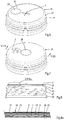
- FIG. 6 shows a screw cap 15 not belonging to the invention.
- the screw cap 15 comprises a central panel 25, a circumferential skirt 26 which is provided at its inner surface with a screw thread 27. In the alternative the thread is formed by the skirt curl 34.
- the central panel is provided with the score 3.
- the central panel is further provided with a vacuum button 28 indicating to the consumer whether a desired vacuum is still present in the closed container.
- FIGs 7 and 8 show a screw cap 24 directly obtained by the method according to the invention.
- the screw cap comprises the central panel 25 and a skirt 26 provided at its inner surface with the screw thread 27.
- the central panel is provided at its center with the vacuum button 28.
- the score 8 is provided in the inner surface of the central panel 25.
- the inner surface 9 is provided with the coating 9. This coating 9 is unitary for the coating of the score 8 and of the entire inner surface 29 of the central panel 25.
- the outer surface 30 of the central panel 25 is provided with a coating 31, and at the ultimate position 32 for the score 8 formed into the inner surface 29 of the central panel 25, with a printing reading "PUSH HERE", see also figure 8a .
- the consumer is directed to the position at the outer surface 30 overlying the score 8 which is to be opened in order to form an open connection in between the interior of the container and the outer atmosphere for release of the vacuum.
- the coating 9 and the coating 31 are such, that when breaking the score 8 also an open connection is formed through the coatings 9 and 31.
- the score generally has a residual material thickness of about 30 ⁇ m to about 70 ⁇ m, such as about 40 ⁇ m to about 60 ⁇ m, typically about 50 ⁇ m.
- the force required for breaking the score is dependent on the residual material thickness and the type of material, and generally is in the order of about 20N to about 70N, such as about 30N to about 60N, such as 40N.
- Other forms suitable are a crescent curved line, closed and open circles, closed and open ovals and the like.
- the reclosable caps directly obtained by the method according to the invention may have a diameter of about 2-30cm, such as 3-30cm and the like.
- the reclosable cap generally has a circular form but also other forms, such as circular forms.
- the reclosable cap may also be provided with a compound at the inner surface and to be connected with the free end of the container opening.
Landscapes
- Engineering & Computer Science (AREA)
- Mechanical Engineering (AREA)
- Closures For Containers (AREA)
Description
- The present invention relates to a method for making a reclosable cap.
- A reclosable cap, such as a reclosable cap reclosable by screwing, also known as a screw cap or twist off cap, is generally used as a closure for a container especially a glass bottle or jar, onto which the reclosable cap is applied, such as by screwing or otherwise. The reclosable cap is tightly applied on to the container. In the interior of the container resides a subatmospheric pressure, such as a vacuum. Such atmospheric pressure is generally created when the container is hot filled, subsequently closed off with the reclosable cap, and the content cooled.
- Due to the internal subatmospheric pressure, the container is relatively difficult to open and a relatively high force is to be applied by the consumer either manually or using a tool for removing the reclosable cap, such as by screwing off the screw cap.
-
DE-A-4240373 discloses a method for making reclosable caps. In the prior art, it is disclosed that a screw cap may be provided with a score forming a weakened section in the screw cap. The score is generally designed such, that by breaking the score manually an open communication is formed with the interior of the container and the vacuum released. Thereby the removal of the screw cap requires less force. - The formation of the score in the metal reclosable cap requires that after scoring the score is to be coated in order to avoid corrosion and/or metal contact with the content of the container. The making of such reclosable cap is difficult, requires specific scoring operations, and is carried out at relatively low production speeds. Such low speed retards the production rate or requires additional parallel scoring operations.
- The present invention has for its object to improve the prior art method for making a reclosable cap, such that this method can be implemented in a standard cap producing process an apparatus, and provides flexibility in the production of various types of reclosable caps, independent of the type and speed of the scoring operation.
- These objects of a method for making a reclosable cap according to the invention are met by providing a method for making a reclosable cap according to
claim 1. - The method according to the invention is based on the insight that by providing the metal part with the score at a location defined by the ultimate position in the reclosable cap, before the metal layer (or metal sheet) is coated the objects of the invention are substantially met and fulfilled. For reasons, that the scored metal layer, or scored metal sheet can be used in the traditional operations and apparatuses for making reclosable caps.
- As indicated above, the method for making the reclosable cap is independent of the ultimate reclosable cap to be made because the presence of the score in a surface does not interfere with the shape and general properties of the reclosable cap, and of the shells. According to a preferred embodiment, the score is formed in the surface of the metal layer forming the outer side of the reclosable cap. On the other hand, according to another preferred embodiment the score is formed in the surface of the metal layer forming the inner side of the reclosable cap. When the score has been made in a surface which ultimately forms the inner side of the reclosable cap, it is not possible for the consumer to monitor the location of the inside score, and does not know where to apply a force for breaking the score. It is therefore preferred, that the non-scored outer surface is provided with a marking for the identification of the location of the inside score.
- Traditionally, any type of lacquer, coating, and/or printing, or the like, may be used for covering the score formed in a metal surface and thereby avoiding exposure of the score. Because such score in the metal surface would be vulnerable to corrosion, and/or make undesired content, in particular food contact. Examples of lacquers, coatings, and printing that could be used, are plastics, such as polyester, polyester-organosol systems, epoxyphenolic systems, acrylic systems, and epoxyanhydride systems. The lacquer or coating may comprise one or more coating layers, such as two or three coating layers of the same or different composition.
- In a first procedure the metal layer which forms a metal strip is cut into a metal sheet, which sheets are scored and then temporarily stored, such as in the form of a stack. Subsequently, in a second procedure, the scored metal sheets are taken from the stack and may be fed in a substantially continuous manner into the coating step (ii) of the method. This provides for flexibility in the production process, particularly for different production rates for on the one hand the scoring and on the other hand the coating step and forming step. Accordingly, according to the invention, the cut and scored metal sheet to be coated in step (ii) originates from a stack of metal sheets.
- The increased flexibility of the method according to the invention allows for the use of a scoring operation which is carried out at a relatively low scoring speed. An example would be a laser scoring operation, a hammer and anvil operation and/or chemical. Accordingly, according to the invention, the scoring is carried out at a relatively low speed, and the coating, cutting and forming of the reclosable cap is carried out at high speed. This overcomes the use of duplication or multiplication of low speed scoring operations in order to produce scored metal sheets at a speed which is comparable to the speed of the remainder method of making reclosable caps. Thus, the method may be implemented into a reclosable cap making method and apparatus functioning at any production speed.
- Another aspect relates to a reclosable cap directly obtained by the method according to the invention, the cap comprising a central panel, a circumferential skirt provided with reclosable means for reclosable attachment to the container or jar, such as a snapping edge or a screw thread, and a score provided in a central panel surface, wherein the score and the central panel surface are provided with a unitary coating, which may comprise one or more, such as two or three coating layers. The presence of a unitary or continuous coating or lacquer covering the score and the surface in which the score has been formed, shows that this reclosable cap has been produced with the method according to the invention. Preferably the central panel surface provided with the score forms the inner side of the reclosable cap and the outer side of the reclosable cap comprises a marking for the location of the score. Accordingly, the consumer is guided and alerted to press at a particular location in order to break the score which is not visible from the outside.
- Mentioned and another characteristic features of the method according to the invention will become apparent from the description from various embodiments of the method according to the invention which are given for illustrative purposes without the intention to restrict the invention thereto. For the description reference is made to the various drawings wherein:
-
Figure 1 shows a metal coil decoiled for providing a metal strip; -
Figure 2 shows the scored metal strip at locations defined by the ultimate position for the score in a screw cap; -
Figure 3 shows a perspective view of a stack of scored metal sheets; -
Figures 4 shows a flow diagram of an examples of a method for making a reclosable cap andfigure 5 shows a flow diagram of an example of a method for making a reclosable cap according to the invention; -
Figures 6 and 7 show perspective views of embodiments of a reclosable cap directly obtained by the method according to the invention; -
Figure 8 is a cross section over the line VIII-VIII infigure 7 ; and -
Figure 8a a droplet magnification of droplet Villa infigure 8 . - The invention will be further illustrated in the description by reference to a reclosable cap directly obtained by the method according to the invention. But it will be evident that other types of reclosable caps, such as a reclosable by snapping, clamping, or the like. But preferred is a cap reclosable by screwing.
-
Figure 1 shows ametal coil 1 which is decoiled providing ametal strip 2. The width of the metal strip is dependent on size and number of screw caps to be made and ranging generally from about 30cm to 150cm, such as 80 to 120cm. The thickness of the metal strip ranges generally from about 0.10mm to about 0.30mm, preferably from about0.14mm to about 0.25 mm, typically about 0.16 mm). The metal for the reclosable cap may be steel, a steel alloy, tin plate, aluminum, aluminum alloy, and mixtures thereof, as well as laminates of metal and a suitable plastic. - Turning to
figure 2 , themetal strip 2 is provided withscores 3 at locations defined by the ultimate position in thereclosable cap 15, of which the outer profile is illustrated byphantom circles 4.Rows 5 ofscores 3 are at mutually offset locations such as to use maximum material from themetal strip 2 and avoid as much as possible metal waste. Themetal strip 2 may be cut according to ascroll line 6 following again the offset positions of therows 5 ofscores 3. Thecut metal sheets 7 provided with thescores 3 are stored in astack 8. In the method according to the invention these cut and scoredmetal sheets 7 are introduced into a coating step for providing at least the scored side of the metal sheet with acoating 9. A suitable coating or lacquer material may be a plastic, such as polyester, polyester-organosol systems, epoxyphenolic systems, acrylic systems, and epoxyanhydride systems. The lacquer or coating may comprise one or more coating layers, such as two or three coating layers of the same or different composition. For a printing coating may be used also for instance a polyester, conventional inks and top coat polyester, and further also conventional UV system. After coating, lacquering and/or printing, and cutting themetal layer 2, ormetal sheet 7 into shells, the screw cap is formed in a traditional manner (not further described). - An example of a method for making a
screw cap 15 not belonging to the invention is illustrated by the flow sheet offigure 4 . Ametal strip 2 is fed in a continuous manner to ascoring unit 10, in which, as illustrated infigure 2 , themetal strip 2 is provided withscores 3 at locations defined by the ultimate position in thescrew caps 15. The scoring operation may be carried out using a number of scoring units, of which the number could be equal to the scores to be provided by one ormore rows 5, seefigure 2 . Eachsuch scoring unit 10 may comprise a laser scoring unit, or a hammer and anvil scoring unit, and/or chemical scoring unit. It is also possible to use a massive pair of rolls provided with projections for imprinting thescores 3 into themetal strip 2. The scoredmetal strip 11 is fed to a lack ring and/orprinting unit 12. At least the side of themetal strip 11 provided with thescores 3, is provided with a lacquer or other type of coating. Particularly, when thescore 3 is to be present at the inside of the screw cap, the other surface of the scored metal strip is provided with a coating or printing, comprising preferably directions or information for the location for theinside score 3. The coated/lacquered and/or printedmetal strip 13 is then fed to aunit 14 for cutting shells and forming thescrew cap 15. - A preferred method for making a
screw cap 24 according to the invention is illustrated in the flow sheet offigure 5 . Themetal strip 2 is fed to aunit 16 for cutting the metal strip intometal sheets 17. Themetal sheet 17 is subsequently carried to astorage unit 18 where thecut metal sheets 17 are stored instacks 8. After storage, the metal sheets are fed to aunit 19 for scoring themetal sheets 17. The scoredmetal sheets 7 are transported to astorage unit 20, where the cut and scoredmetal sheets 7 are stored in stacks. Thereafter, the scoredmetal sheets 7 are fed to a lacquering/coating/printing unit 21 for providing at least the side provided with thescores 3, with a lacquer or coating. If relevant or preferred, the other side may be provided with a coating and/or printing. The scored and at leastcoated metal sheets 22 are transported to aunit 23 for cutting shells and formingscrew cap 24 from the shells. -
Figure 6 shows ascrew cap 15 not belonging to the invention. Thescrew cap 15 comprises acentral panel 25, acircumferential skirt 26 which is provided at its inner surface with ascrew thread 27. In the alternative the thread is formed by the skirt curl 34. The central panel is provided with thescore 3. The central panel is further provided with avacuum button 28 indicating to the consumer whether a desired vacuum is still present in the closed container. -
Figures 7 and 8 show ascrew cap 24 directly obtained by the method according to the invention. The screw cap comprises thecentral panel 25 and askirt 26 provided at its inner surface with thescrew thread 27. The central panel is provided at its center with thevacuum button 28. Thescore 8 is provided in the inner surface of thecentral panel 25. Theinner surface 9 is provided with thecoating 9. Thiscoating 9 is unitary for the coating of thescore 8 and of the entireinner surface 29 of thecentral panel 25. Theouter surface 30 of thecentral panel 25 is provided with acoating 31, and at theultimate position 32 for thescore 8 formed into theinner surface 29 of thecentral panel 25, with a printing reading "PUSH HERE", see alsofigure 8a . Accordingly, the consumer is directed to the position at theouter surface 30 overlying thescore 8 which is to be opened in order to form an open connection in between the interior of the container and the outer atmosphere for release of the vacuum. Obviously, thecoating 9 and thecoating 31 are such, that when breaking thescore 8 also an open connection is formed through thecoatings - Although the scores have been described in the form of crossed lines, it will be apparent that any form of score is suitable for use within the ambit according to the invention, as long as by the application of some manual force by the consumer the score will be broken and an open communication with the interior of the container formed for vacuum release. The score generally has a residual material thickness of about 30µm to about 70µm, such as about 40µm to about 60µm, typically about 50µm. The force required for breaking the score is dependent on the residual material thickness and the type of material, and generally is in the order of about 20N to about 70N, such as about 30N to about 60N, such as 40N. Other forms suitable are a crescent curved line, closed and open circles, closed and open ovals and the like.
- The reclosable caps directly obtained by the method according to the invention may have a diameter of about 2-30cm, such as 3-30cm and the like. The reclosable cap generally has a circular form but also other forms, such as circular forms.
- If required for a proper air tight closing of the reclosable cap on the container, the reclosable cap may also be provided with a compound at the inner surface and to be connected with the free end of the container opening.
Claims (7)
- Method for making a reclosable cap (24), such as a reclosable cap reclosable by screwing, comprising the steps of:i) providing a metal layer with a plurality of scores (3) at locations defined by an ultimate position in the reclosable caps (24) to be formed out of the metal layer;ii) providing the scored metal layer (7) on at least the scored side with a coating (9);iii) cutting shells from the scored metal layer, which shells include a score; andiv) forming a reclosable cap (24) from the shell, with the score at the ultimate position,characterized in that the scoring is carried out by low speed scoring , and the coating, cutting and forming of the reclosable (24) cap is carried out at high speed, and that the metal layer comprises a metal sheet (17) cut from a metal strip (2) forming the metal layer and stored on a stack (8), and the cut and scored metal sheet (7) to be coated in step (ii) originates from the stack (8) of metal sheets.
- Method as claimed in claim 1, wherein the score (3) is formed in the surface of the metal layer forming the outer side of the reclosable cap (24).
- Method as claimed by claim 1, wherein the score (3) is formed in the surface of the metal layer forming the inner side of the reclosable cap (24).
- Method as claimed in claim 3, wherein the non-scored outer surface is provided with a marking for the location of the inward score.
- Method as claimed in claims 1-4, wherein the coating (9) is a lacquer or print.
- Method as claimed in claims 1-5, wherein the low speed scoring is laser scoring.
- Method as claimed in claims 1-6, wherein the reclosable cap (24) is provided with external lacquer or coloured coating or printing.
Priority Applications (5)
| Application Number | Priority Date | Filing Date | Title |
|---|---|---|---|
| DK13183964.9T DK2848331T3 (en) | 2013-09-11 | 2013-09-11 | PROCEDURE FOR MAKING A LOCKABLE COVER |
| PL13183964T PL2848331T3 (en) | 2013-09-11 | 2013-09-11 | Method for making a reclosable cap |
| EP13183964.9A EP2848331B1 (en) | 2013-09-11 | 2013-09-11 | Method for making a reclosable cap |
| ES13183964T ES2904605T3 (en) | 2013-09-11 | 2013-09-11 | Method for making a resealable lid |
| HUE13183964A HUE057654T2 (en) | 2013-09-11 | 2013-09-11 | Method for making a reclosable cap |
Applications Claiming Priority (1)
| Application Number | Priority Date | Filing Date | Title |
|---|---|---|---|
| EP13183964.9A EP2848331B1 (en) | 2013-09-11 | 2013-09-11 | Method for making a reclosable cap |
Publications (2)
| Publication Number | Publication Date |
|---|---|
| EP2848331A1 EP2848331A1 (en) | 2015-03-18 |
| EP2848331B1 true EP2848331B1 (en) | 2021-12-22 |
Family
ID=49162015
Family Applications (1)
| Application Number | Title | Priority Date | Filing Date |
|---|---|---|---|
| EP13183964.9A Active EP2848331B1 (en) | 2013-09-11 | 2013-09-11 | Method for making a reclosable cap |
Country Status (5)
| Country | Link |
|---|---|
| EP (1) | EP2848331B1 (en) |
| DK (1) | DK2848331T3 (en) |
| ES (1) | ES2904605T3 (en) |
| HU (1) | HUE057654T2 (en) |
| PL (1) | PL2848331T3 (en) |
Family Cites Families (4)
| Publication number | Priority date | Publication date | Assignee | Title |
|---|---|---|---|---|
| US3410436A (en) * | 1966-09-23 | 1968-11-12 | Anchor Hocking Glass Corp | Closure cap with venting means |
| DE2010631C3 (en) * | 1970-03-06 | 1975-10-16 | Rasselstein Ag, 5450 Neuwied | Process for the production of tear-off lids from sheet metal |
| DE4240373A1 (en) * | 1992-12-01 | 1994-06-09 | Basf Lacke & Farben | Process for the production of tear-open covers and tear-open covers produced according to this process |
| NL2006323C2 (en) * | 2011-03-01 | 2012-09-05 | E & E Holding B V | METHOD FOR MANUFACTURING A SCREW COVER AND A SCREW COVER FOR SHUTTING A CANNED POT. |
-
2013
- 2013-09-11 ES ES13183964T patent/ES2904605T3/en active Active
- 2013-09-11 PL PL13183964T patent/PL2848331T3/en unknown
- 2013-09-11 HU HUE13183964A patent/HUE057654T2/en unknown
- 2013-09-11 DK DK13183964.9T patent/DK2848331T3/en active
- 2013-09-11 EP EP13183964.9A patent/EP2848331B1/en active Active
Also Published As
| Publication number | Publication date |
|---|---|
| EP2848331A1 (en) | 2015-03-18 |
| PL2848331T3 (en) | 2022-03-07 |
| ES2904605T3 (en) | 2022-04-05 |
| HUE057654T2 (en) | 2022-05-28 |
| DK2848331T3 (en) | 2022-01-17 |
Similar Documents
| Publication | Publication Date | Title |
|---|---|---|
| US10081484B2 (en) | Easy opening reclose systems for cigarette packaging | |
| WO2006111177A1 (en) | Film packaging having tamper-evident means | |
| US20160122068A1 (en) | Beverage container | |
| JP6896455B2 (en) | Resin-coated bottle-shaped cans, their manufacturing methods, and resin-coated metal plates | |
| TW202330954A (en) | Food or beverage can lid | |
| CN101708525A (en) | Aluminum two-sheet zip-top can and aluminum material thinning method thereof | |
| EP2416903B1 (en) | Method of manufacturing a metal vessel | |
| EP2848331B1 (en) | Method for making a reclosable cap | |
| CN201553353U (en) | Aluminium-made two-piece pop can with capacity of 500ml | |
| CN201553354U (en) | Aluminium-made two-piece pop can with capacity of 500ml | |
| US3397661A (en) | Closure with protective coating and method of manufacture thereof | |
| US20110056949A1 (en) | Package consisting of a container and a lid | |
| JP4514119B2 (en) | Metal can for wine canning | |
| EP3862289A1 (en) | Mono-web package with tamper-evident tear strip and resealable flap portion | |
| CA2723794C (en) | A lidding system and lids for plastic or metal containers | |
| EP1304217B1 (en) | Production process of seminanufactured bright tapes | |
| JP2004026306A (en) | Opening curl section of metal can | |
| US20150266645A1 (en) | Re-sealable lid films and labels and systems and methods for producing the same | |
| JP4793895B2 (en) | Seamless can having white appearance and method for producing the same | |
| CN108883855B (en) | Packaging container and method for disassembling same | |
| JP4775988B2 (en) | Resin-coated seamless can and method for producing the same | |
| JP2004025233A (en) | Production method of metal cap | |
| JP7243089B2 (en) | Easy-open paper container | |
| JP7027980B2 (en) | Laminated tube container with large uneven pattern and fine uneven pattern | |
| JP2002337866A (en) | Steel can with excellent printed appearance and method for manufacturing the same |
Legal Events
| Date | Code | Title | Description |
|---|---|---|---|
| PUAI | Public reference made under article 153(3) epc to a published international application that has entered the european phase |
Free format text: ORIGINAL CODE: 0009012 |
|
| 17P | Request for examination filed |
Effective date: 20130911 |
|
| AK | Designated contracting states |
Kind code of ref document: A1 Designated state(s): AL AT BE BG CH CY CZ DE DK EE ES FI FR GB GR HR HU IE IS IT LI LT LU LV MC MK MT NL NO PL PT RO RS SE SI SK SM TR |
|
| AX | Request for extension of the european patent |
Extension state: BA ME |
|
| R17P | Request for examination filed (corrected) |
Effective date: 20151215 |
|
| RBV | Designated contracting states (corrected) |
Designated state(s): AL AT BE BG CH CY CZ DE DK EE ES FI FR GB GR HR HU IE IS IT LI LT LU LV MC MK MT NL NO PL PT RO RS SE SI SK SM TR |
|
| STAA | Information on the status of an ep patent application or granted ep patent |
Free format text: STATUS: EXAMINATION IS IN PROGRESS |
|
| 17Q | First examination report despatched |
Effective date: 20190808 |
|
| STAA | Information on the status of an ep patent application or granted ep patent |
Free format text: STATUS: EXAMINATION IS IN PROGRESS |
|
| GRAP | Despatch of communication of intention to grant a patent |
Free format text: ORIGINAL CODE: EPIDOSNIGR1 |
|
| STAA | Information on the status of an ep patent application or granted ep patent |
Free format text: STATUS: GRANT OF PATENT IS INTENDED |
|
| INTG | Intention to grant announced |
Effective date: 20210208 |
|
| GRAJ | Information related to disapproval of communication of intention to grant by the applicant or resumption of examination proceedings by the epo deleted |
Free format text: ORIGINAL CODE: EPIDOSDIGR1 |
|
| STAA | Information on the status of an ep patent application or granted ep patent |
Free format text: STATUS: EXAMINATION IS IN PROGRESS |
|
| GRAP | Despatch of communication of intention to grant a patent |
Free format text: ORIGINAL CODE: EPIDOSNIGR1 |
|
| STAA | Information on the status of an ep patent application or granted ep patent |
Free format text: STATUS: GRANT OF PATENT IS INTENDED |
|
| INTC | Intention to grant announced (deleted) | ||
| INTG | Intention to grant announced |
Effective date: 20210714 |
|
| GRAS | Grant fee paid |
Free format text: ORIGINAL CODE: EPIDOSNIGR3 |
|
| GRAA | (expected) grant |
Free format text: ORIGINAL CODE: 0009210 |
|
| STAA | Information on the status of an ep patent application or granted ep patent |
Free format text: STATUS: THE PATENT HAS BEEN GRANTED |
|
| AK | Designated contracting states |
Kind code of ref document: B1 Designated state(s): AL AT BE BG CH CY CZ DE DK EE ES FI FR GB GR HR HU IE IS IT LI LT LU LV MC MK MT NL NO PL PT RO RS SE SI SK SM TR |
|
| REG | Reference to a national code |
Ref country code: GB Ref legal event code: FG4D |
|
| REG | Reference to a national code |
Ref country code: CH Ref legal event code: EP |
|
| REG | Reference to a national code |
Ref country code: DE Ref legal event code: R096 Ref document number: 602013080475 Country of ref document: DE |
|
| REG | Reference to a national code |
Ref country code: AT Ref legal event code: REF Ref document number: 1456744 Country of ref document: AT Kind code of ref document: T Effective date: 20220115 |
|
| REG | Reference to a national code |
Ref country code: DK Ref legal event code: T3 Effective date: 20220111 |
|
| REG | Reference to a national code |
Ref country code: IE Ref legal event code: FG4D |
|
| REG | Reference to a national code |
Ref country code: NL Ref legal event code: FP |
|
| REG | Reference to a national code |
Ref country code: ES Ref legal event code: FG2A Ref document number: 2904605 Country of ref document: ES Kind code of ref document: T3 Effective date: 20220405 |
|
| REG | Reference to a national code |
Ref country code: LT Ref legal event code: MG9D |
|
| PG25 | Lapsed in a contracting state [announced via postgrant information from national office to epo] |
Ref country code: RS Free format text: LAPSE BECAUSE OF FAILURE TO SUBMIT A TRANSLATION OF THE DESCRIPTION OR TO PAY THE FEE WITHIN THE PRESCRIBED TIME-LIMIT Effective date: 20211222 Ref country code: LT Free format text: LAPSE BECAUSE OF FAILURE TO SUBMIT A TRANSLATION OF THE DESCRIPTION OR TO PAY THE FEE WITHIN THE PRESCRIBED TIME-LIMIT Effective date: 20211222 Ref country code: FI Free format text: LAPSE BECAUSE OF FAILURE TO SUBMIT A TRANSLATION OF THE DESCRIPTION OR TO PAY THE FEE WITHIN THE PRESCRIBED TIME-LIMIT Effective date: 20211222 Ref country code: BG Free format text: LAPSE BECAUSE OF FAILURE TO SUBMIT A TRANSLATION OF THE DESCRIPTION OR TO PAY THE FEE WITHIN THE PRESCRIBED TIME-LIMIT Effective date: 20220322 |
|
| REG | Reference to a national code |
Ref country code: AT Ref legal event code: MK05 Ref document number: 1456744 Country of ref document: AT Kind code of ref document: T Effective date: 20211222 |
|
| REG | Reference to a national code |
Ref country code: HU Ref legal event code: AG4A Ref document number: E057654 Country of ref document: HU |
|
| PG25 | Lapsed in a contracting state [announced via postgrant information from national office to epo] |
Ref country code: SE Free format text: LAPSE BECAUSE OF FAILURE TO SUBMIT A TRANSLATION OF THE DESCRIPTION OR TO PAY THE FEE WITHIN THE PRESCRIBED TIME-LIMIT Effective date: 20211222 Ref country code: NO Free format text: LAPSE BECAUSE OF FAILURE TO SUBMIT A TRANSLATION OF THE DESCRIPTION OR TO PAY THE FEE WITHIN THE PRESCRIBED TIME-LIMIT Effective date: 20220322 Ref country code: LV Free format text: LAPSE BECAUSE OF FAILURE TO SUBMIT A TRANSLATION OF THE DESCRIPTION OR TO PAY THE FEE WITHIN THE PRESCRIBED TIME-LIMIT Effective date: 20211222 Ref country code: HR Free format text: LAPSE BECAUSE OF FAILURE TO SUBMIT A TRANSLATION OF THE DESCRIPTION OR TO PAY THE FEE WITHIN THE PRESCRIBED TIME-LIMIT Effective date: 20211222 Ref country code: GR Free format text: LAPSE BECAUSE OF FAILURE TO SUBMIT A TRANSLATION OF THE DESCRIPTION OR TO PAY THE FEE WITHIN THE PRESCRIBED TIME-LIMIT Effective date: 20220323 |
|
| PG25 | Lapsed in a contracting state [announced via postgrant information from national office to epo] |
Ref country code: SM Free format text: LAPSE BECAUSE OF FAILURE TO SUBMIT A TRANSLATION OF THE DESCRIPTION OR TO PAY THE FEE WITHIN THE PRESCRIBED TIME-LIMIT Effective date: 20211222 Ref country code: SK Free format text: LAPSE BECAUSE OF FAILURE TO SUBMIT A TRANSLATION OF THE DESCRIPTION OR TO PAY THE FEE WITHIN THE PRESCRIBED TIME-LIMIT Effective date: 20211222 Ref country code: PT Free format text: LAPSE BECAUSE OF FAILURE TO SUBMIT A TRANSLATION OF THE DESCRIPTION OR TO PAY THE FEE WITHIN THE PRESCRIBED TIME-LIMIT Effective date: 20220422 Ref country code: EE Free format text: LAPSE BECAUSE OF FAILURE TO SUBMIT A TRANSLATION OF THE DESCRIPTION OR TO PAY THE FEE WITHIN THE PRESCRIBED TIME-LIMIT Effective date: 20211222 |
|
| PG25 | Lapsed in a contracting state [announced via postgrant information from national office to epo] |
Ref country code: AT Free format text: LAPSE BECAUSE OF FAILURE TO SUBMIT A TRANSLATION OF THE DESCRIPTION OR TO PAY THE FEE WITHIN THE PRESCRIBED TIME-LIMIT Effective date: 20211222 |
|
| REG | Reference to a national code |
Ref country code: DE Ref legal event code: R097 Ref document number: 602013080475 Country of ref document: DE |
|
| PG25 | Lapsed in a contracting state [announced via postgrant information from national office to epo] |
Ref country code: IS Free format text: LAPSE BECAUSE OF FAILURE TO SUBMIT A TRANSLATION OF THE DESCRIPTION OR TO PAY THE FEE WITHIN THE PRESCRIBED TIME-LIMIT Effective date: 20220422 |
|
| PLBE | No opposition filed within time limit |
Free format text: ORIGINAL CODE: 0009261 |
|
| STAA | Information on the status of an ep patent application or granted ep patent |
Free format text: STATUS: NO OPPOSITION FILED WITHIN TIME LIMIT |
|
| PG25 | Lapsed in a contracting state [announced via postgrant information from national office to epo] |
Ref country code: AL Free format text: LAPSE BECAUSE OF FAILURE TO SUBMIT A TRANSLATION OF THE DESCRIPTION OR TO PAY THE FEE WITHIN THE PRESCRIBED TIME-LIMIT Effective date: 20211222 |
|
| PGFP | Annual fee paid to national office [announced via postgrant information from national office to epo] |
Ref country code: RO Payment date: 20220906 Year of fee payment: 10 Ref country code: NL Payment date: 20220926 Year of fee payment: 10 Ref country code: GB Payment date: 20220927 Year of fee payment: 10 Ref country code: DK Payment date: 20220928 Year of fee payment: 10 Ref country code: DE Payment date: 20220928 Year of fee payment: 10 Ref country code: CZ Payment date: 20220831 Year of fee payment: 10 |
|
| 26N | No opposition filed |
Effective date: 20220923 |
|
| PGFP | Annual fee paid to national office [announced via postgrant information from national office to epo] |
Ref country code: PL Payment date: 20220902 Year of fee payment: 10 Ref country code: HU Payment date: 20220910 Year of fee payment: 10 Ref country code: FR Payment date: 20220926 Year of fee payment: 10 |
|
| PGFP | Annual fee paid to national office [announced via postgrant information from national office to epo] |
Ref country code: ES Payment date: 20221003 Year of fee payment: 10 |
|
| PG25 | Lapsed in a contracting state [announced via postgrant information from national office to epo] |
Ref country code: SI Free format text: LAPSE BECAUSE OF FAILURE TO SUBMIT A TRANSLATION OF THE DESCRIPTION OR TO PAY THE FEE WITHIN THE PRESCRIBED TIME-LIMIT Effective date: 20211222 |
|
| PG25 | Lapsed in a contracting state [announced via postgrant information from national office to epo] |
Ref country code: MC Free format text: LAPSE BECAUSE OF FAILURE TO SUBMIT A TRANSLATION OF THE DESCRIPTION OR TO PAY THE FEE WITHIN THE PRESCRIBED TIME-LIMIT Effective date: 20211222 |
|
| REG | Reference to a national code |
Ref country code: CH Ref legal event code: PL |
|
| REG | Reference to a national code |
Ref country code: BE Ref legal event code: MM Effective date: 20220930 |
|
| PG25 | Lapsed in a contracting state [announced via postgrant information from national office to epo] |
Ref country code: LU Free format text: LAPSE BECAUSE OF NON-PAYMENT OF DUE FEES Effective date: 20220911 |
|
| PG25 | Lapsed in a contracting state [announced via postgrant information from national office to epo] |
Ref country code: LI Free format text: LAPSE BECAUSE OF NON-PAYMENT OF DUE FEES Effective date: 20220930 Ref country code: IE Free format text: LAPSE BECAUSE OF NON-PAYMENT OF DUE FEES Effective date: 20220911 Ref country code: CH Free format text: LAPSE BECAUSE OF NON-PAYMENT OF DUE FEES Effective date: 20220930 |
|
| P01 | Opt-out of the competence of the unified patent court (upc) registered |
Effective date: 20230719 |
|
| PG25 | Lapsed in a contracting state [announced via postgrant information from national office to epo] |
Ref country code: BE Free format text: LAPSE BECAUSE OF NON-PAYMENT OF DUE FEES Effective date: 20220930 |
|
| REG | Reference to a national code |
Ref country code: DE Ref legal event code: R119 Ref document number: 602013080475 Country of ref document: DE |
|
| REG | Reference to a national code |
Ref country code: DK Ref legal event code: EBP Effective date: 20230930 |
|
| PG25 | Lapsed in a contracting state [announced via postgrant information from national office to epo] |
Ref country code: RO Free format text: LAPSE BECAUSE OF NON-PAYMENT OF DUE FEES Effective date: 20230911 Ref country code: CZ Free format text: LAPSE BECAUSE OF NON-PAYMENT OF DUE FEES Effective date: 20230911 Ref country code: CY Free format text: LAPSE BECAUSE OF FAILURE TO SUBMIT A TRANSLATION OF THE DESCRIPTION OR TO PAY THE FEE WITHIN THE PRESCRIBED TIME-LIMIT Effective date: 20211222 |
|
| REG | Reference to a national code |
Ref country code: NL Ref legal event code: MM Effective date: 20231001 |
|
| GBPC | Gb: european patent ceased through non-payment of renewal fee |
Effective date: 20230911 |
|
| PG25 | Lapsed in a contracting state [announced via postgrant information from national office to epo] |
Ref country code: MK Free format text: LAPSE BECAUSE OF FAILURE TO SUBMIT A TRANSLATION OF THE DESCRIPTION OR TO PAY THE FEE WITHIN THE PRESCRIBED TIME-LIMIT Effective date: 20211222 |
|
| PGFP | Annual fee paid to national office [announced via postgrant information from national office to epo] |
Ref country code: IT Payment date: 20220926 Year of fee payment: 10 |
|
| PG25 | Lapsed in a contracting state [announced via postgrant information from national office to epo] |
Ref country code: NL Free format text: LAPSE BECAUSE OF NON-PAYMENT OF DUE FEES Effective date: 20231001 |
|
| PG25 | Lapsed in a contracting state [announced via postgrant information from national office to epo] |
Ref country code: TR Free format text: LAPSE BECAUSE OF FAILURE TO SUBMIT A TRANSLATION OF THE DESCRIPTION OR TO PAY THE FEE WITHIN THE PRESCRIBED TIME-LIMIT Effective date: 20211222 Ref country code: NL Free format text: LAPSE BECAUSE OF NON-PAYMENT OF DUE FEES Effective date: 20231001 |
|
| PG25 | Lapsed in a contracting state [announced via postgrant information from national office to epo] |
Ref country code: GB Free format text: LAPSE BECAUSE OF NON-PAYMENT OF DUE FEES Effective date: 20230911 |
|
| PG25 | Lapsed in a contracting state [announced via postgrant information from national office to epo] |
Ref country code: GB Free format text: LAPSE BECAUSE OF NON-PAYMENT OF DUE FEES Effective date: 20230911 Ref country code: FR Free format text: LAPSE BECAUSE OF NON-PAYMENT OF DUE FEES Effective date: 20230930 Ref country code: DE Free format text: LAPSE BECAUSE OF NON-PAYMENT OF DUE FEES Effective date: 20240403 |
|
| PG25 | Lapsed in a contracting state [announced via postgrant information from national office to epo] |
Ref country code: HU Free format text: LAPSE BECAUSE OF NON-PAYMENT OF DUE FEES Effective date: 20230912 |
|
| PG25 | Lapsed in a contracting state [announced via postgrant information from national office to epo] |
Ref country code: MT Free format text: LAPSE BECAUSE OF FAILURE TO SUBMIT A TRANSLATION OF THE DESCRIPTION OR TO PAY THE FEE WITHIN THE PRESCRIBED TIME-LIMIT Effective date: 20211222 |