EP2848309B1 - Träger für kapillaren - Google Patents
Träger für kapillaren Download PDFInfo
- Publication number
- EP2848309B1 EP2848309B1 EP13184379.9A EP13184379A EP2848309B1 EP 2848309 B1 EP2848309 B1 EP 2848309B1 EP 13184379 A EP13184379 A EP 13184379A EP 2848309 B1 EP2848309 B1 EP 2848309B1
- Authority
- EP
- European Patent Office
- Prior art keywords
- capillaries
- array
- carrier
- filling
- capillary
- Prior art date
- Legal status (The legal status is an assumption and is not a legal conclusion. Google has not performed a legal analysis and makes no representation as to the accuracy of the status listed.)
- Active
Links
Images





Classifications
-
- G—PHYSICS
- G01—MEASURING; TESTING
- G01N—INVESTIGATING OR ANALYSING MATERIALS BY DETERMINING THEIR CHEMICAL OR PHYSICAL PROPERTIES
- G01N21/00—Investigating or analysing materials by the use of optical means, i.e. using sub-millimetre waves, infrared, visible or ultraviolet light
- G01N21/01—Arrangements or apparatus for facilitating the optical investigation
- G01N21/03—Cuvette constructions
-
- B—PERFORMING OPERATIONS; TRANSPORTING
- B01—PHYSICAL OR CHEMICAL PROCESSES OR APPARATUS IN GENERAL
- B01L—CHEMICAL OR PHYSICAL LABORATORY APPARATUS FOR GENERAL USE
- B01L9/00—Supporting devices; Holding devices
- B01L9/06—Test-tube stands; Test-tube holders
- B01L9/065—Test-tube stands; Test-tube holders specially adapted for capillary tubes
-
- G—PHYSICS
- G01—MEASURING; TESTING
- G01N—INVESTIGATING OR ANALYSING MATERIALS BY DETERMINING THEIR CHEMICAL OR PHYSICAL PROPERTIES
- G01N21/00—Investigating or analysing materials by the use of optical means, i.e. using sub-millimetre waves, infrared, visible or ultraviolet light
- G01N21/01—Arrangements or apparatus for facilitating the optical investigation
- G01N21/11—Filling or emptying of cuvettes
-
- G—PHYSICS
- G01—MEASURING; TESTING
- G01N—INVESTIGATING OR ANALYSING MATERIALS BY DETERMINING THEIR CHEMICAL OR PHYSICAL PROPERTIES
- G01N21/00—Investigating or analysing materials by the use of optical means, i.e. using sub-millimetre waves, infrared, visible or ultraviolet light
- G01N21/01—Arrangements or apparatus for facilitating the optical investigation
- G01N21/13—Moving of cuvettes or solid samples to or from the investigating station
-
- G—PHYSICS
- G01—MEASURING; TESTING
- G01N—INVESTIGATING OR ANALYSING MATERIALS BY DETERMINING THEIR CHEMICAL OR PHYSICAL PROPERTIES
- G01N21/00—Investigating or analysing materials by the use of optical means, i.e. using sub-millimetre waves, infrared, visible or ultraviolet light
- G01N21/62—Systems in which the material investigated is excited whereby it emits light or causes a change in wavelength of the incident light
- G01N21/71—Systems in which the material investigated is excited whereby it emits light or causes a change in wavelength of the incident light thermally excited
-
- B—PERFORMING OPERATIONS; TRANSPORTING
- B01—PHYSICAL OR CHEMICAL PROCESSES OR APPARATUS IN GENERAL
- B01L—CHEMICAL OR PHYSICAL LABORATORY APPARATUS FOR GENERAL USE
- B01L2300/00—Additional constructional details
- B01L2300/08—Geometry, shape and general structure
- B01L2300/0832—Geometry, shape and general structure cylindrical, tube shaped
- B01L2300/0838—Capillaries
-
- B—PERFORMING OPERATIONS; TRANSPORTING
- B01—PHYSICAL OR CHEMICAL PROCESSES OR APPARATUS IN GENERAL
- B01L—CHEMICAL OR PHYSICAL LABORATORY APPARATUS FOR GENERAL USE
- B01L2400/00—Moving or stopping fluids
- B01L2400/04—Moving fluids with specific forces or mechanical means
- B01L2400/0403—Moving fluids with specific forces or mechanical means specific forces
- B01L2400/0406—Moving fluids with specific forces or mechanical means specific forces capillary forces
-
- B—PERFORMING OPERATIONS; TRANSPORTING
- B01—PHYSICAL OR CHEMICAL PROCESSES OR APPARATUS IN GENERAL
- B01L—CHEMICAL OR PHYSICAL LABORATORY APPARATUS FOR GENERAL USE
- B01L7/00—Heating or cooling apparatus; Heat insulating devices
-
- G—PHYSICS
- G01—MEASURING; TESTING
- G01N—INVESTIGATING OR ANALYSING MATERIALS BY DETERMINING THEIR CHEMICAL OR PHYSICAL PROPERTIES
- G01N2201/00—Features of devices classified in G01N21/00
- G01N2201/02—Mechanical
-
- G—PHYSICS
- G01—MEASURING; TESTING
- G01N—INVESTIGATING OR ANALYSING MATERIALS BY DETERMINING THEIR CHEMICAL OR PHYSICAL PROPERTIES
- G01N2201/00—Features of devices classified in G01N21/00
- G01N2201/04—Batch operation; multisample devices
Definitions
- the invention generally relates to a carrier for capillaries.
- the invention relates to a carrier for a plurality of capillaries with which a simultaneous filling of several capillaries from a microtiter plate is made possible.
- the present invention also relates to a device and a method for filling, transporting and measuring liquids with volumes in the microliter range.
- magnetic beads are used in the liquids. These substances or “magnetic beads” cannot be used with the magnetic capillaries because they are there from the magnetic fields, e.g. are negatively influenced by the magnetic fields that hold the magnetic capillaries or by the magnetic material on the capillary itself.
- Magnetic capillaries cannot be used in applications such as NMR (nuclear magnetic resonance), which also work with magnetic fields.
- a micro-cuvette array Optim 1000, from ForteBio is known, in which 16 micro-cuvettes are arranged in recesses in a carrier and manually individually or by means of a Multichannel pipette to be filled.
- the array must be tightly sealed after filling the microcuvettes and is then fed to an analysis device.
- the filling of these microcuvettes can only be done laboriously by hand.
- the filling of the microcuvettes is difficult to understand or check and the microcuvettes are so short that the evaporation of the liquid is a very big problem, which means that a complex seal is necessary.
- EP1695762 A2 discloses a carrier with capillaries, consist of a compact structure which has a connecting web and a series of pyramidal structures, each of which carries a capillary.
- WO03066667 A2 discloses another flexible support with capillaries arranged in parallel.
- the device according to the invention is preferably intended to hold a number of capillaries which are used, for example, for optical microscale thermophoresis measurements, preferably in devices from NanoTemper Technologies GmbH.
- the plurality of capillaries are preferably arranged in one plane and mechanically attached to the support, the distance between adjacent capillaries preferably being 2.25 mm or an integral multiple thereof. At least a first free end of each capillary projects beyond the carrier in such a way that these free ends of the capillaries can be inserted simultaneously into cavities in a microtiter plate.
- the carrier on which the capillaries are attached should not be completely opaque to light, since an optical measurement perpendicular to the longitudinal axis of the capillary could then be made more difficult.
- the carrier should have a light-permeable area along the longitudinal axis of each capillary, also referred to below as the measuring area or measuring window or measuring recess.
- the support in the measuring area can have a reflective and / or absorbing area or a reflecting and / or absorbing material, preferably this area or this material has a low auto-fluorescence, preferably no auto-fluorescence.
- 24 capillaries are mechanically attached to a carrier according to the invention.
- the capillaries have a center-to-center distance of 4.5 mm. This distance corresponds to the grid of the cavities in the Industry standard for 384 microtiter plates (multiwell plate; 24 x 16 cavities in 4.5 mm center-to-center distance).
- a carrier according to the invention with 24 capillaries thus corresponds to a "row” (numbering 1 to 24, "landscape” orientation) of this 384 microtiter plate (see, for example, http://de.wikipedia.org/wiki / Microtiter plate).
- microtiter plates are mostly made of plastic (usually polystyrenes, sometimes also polyvinyl chloride), and for very special applications also made of glass. They contain many wells that are isolated from one another (wells) in rows and columns. The exact dimensions (length ⁇ width ⁇ height) are 127.76 mm ⁇ 85.48 mm ⁇ 14.35 mm according to the ANSI standard recommended by the Society for Biomolecular Screening (SBS).
- the bowls are available in different shapes: F-bottom (flat bottom), C-bottom (flat bottom with minimally rounded corners), V-bottom (tapered bottom) and U-bottom (U-shaped recess).
- Standardization has so far been carried out, for example, by the Society for Biomolecular Sciences as ANSI standards (ANSI / SBS 1-2004, ANSI / SBS 2-2004, ANSI / SBS 3-2004, ANSI / SBS 4-2004).
- the distances between microtiter plates are also defined in these standards.
- this standard specifies the spacing between adjacent columns and rows for 96, 384 and 1536 microtiter plates. With 96-well microtiter plates, the distance between two rows or two columns is 9mm; with 384 microtiter plates, the distance between two rows or two columns is 4.5 mm; and with 1536 microtiter plates, the distance between two rows or two columns is 2.25 mm.
- the carrier with the 24 capillaries is immersed in the 384 plate, the 24 capillaries being able to soak up on their own within a few seconds due to the capillary forces.
- the carrier with the filled capillaries can then be placed in / on a holder (hereinafter also referred to as a tray) which can accommodate several carriers.
- a tray can preferably hold up to four of the carriers according to the invention.
- the tray is then pushed into an appropriate measuring device, e.g. from NanoTemper®.
- the carrier is easier to handle than individual capillaries, protects the capillaries from mechanical damage and soiling, for example fingerprints from the their autofluorescence can interfere with the optical measurements, which significantly increases the process reliability.
- the carrier prevents the confusion and / or interchanging of individual capillaries and, by means of a preferably unique identification, enables a preferably unambiguous subsequent verification / documentation / assignment of samples to be examined to capillaries and carriers, which is advantageous for diagnostic and analytical applications such as drug research or drug formulation.
- the present invention also relates to the tray, which serves as a storage or storage box for receiving at least one, preferably two, three, four or even more carriers according to the invention.
- the carrier according to the invention and the tray according to the invention thus lead to a massive reduction in the course of actions.
- the carrier with 24 capillaries described by way of example can preferably not only be used for 384 microtiter plates, but is also compatible, for example, for 96 microtiter plates (9 mm grid); in this case e.g. 2 capillaries (together) one cavity of the microtiter plate.
- the carrier according to the invention is preferably not only usable manually by a person for (filling) filling and / or measuring, but preferably also automatically, e.g. can be handled by pipetting robots.
- the carrier according to the invention is preferably clearly identified, for example in order to clearly assign measurement data to samples. For example, labeling using DataMatrix Code, RFiD, etc. with a "unique ID", which enables traceability of the measurements, for example for quality control and / or diagnostic applications.
- the present invention also relates to a filling station.
- the capillaries of a carrier according to the invention can preferably be filled simply and safely. Since not all users work with microtiter plates, an alternative or additional filling of the capillaries is preferably also possible.
- the capillaries can be filled using a single-channel and / or multi-channel pipette, preferably manually. Manual filling is preferably carried out from above. For smaller test series or preliminary tests, partial areas of the carrier can also be filled, ie not all capillaries of the carrier are filled.
- the capillaries preferably fill by themselves, i.e. only by capillary forces when the capillaries are immersed in a liquid.
- no pumps or other active elements are required to fill the capillaries.
- additional devices or elements for filling the capillaries can be used alternatively or additionally.
- the capillaries of the carrier according to the invention can also be filled using a pipette (see, for example, the discussion above with respect to the filling station).
- the capillaries preferably meet at least one of the following criteria.
- the capillaries should have a small inner diameter (ID).
- ID inner diameter
- the capillary forces depend on the inner radius / diameter of the capillary.
- the height of the liquid within the capillaries also depends on the surface tension and the density of the liquid.
- different inner radii / inner diameters can be preferred for liquids with different densities.
- the liquid will be an aqueous solution.
- Preferred inner diameters are, for example, in the range from 0.01 mm to 1.0 mm, more preferably in the range from 0.1 mm to 0.5 mm.
- the capillary forces must draw in the liquid column against gravitation. If, for example, there is a detergent or another substance in the solution / liquid that reduces the capillary forces / surface forces, the capillary forces can be too weak if the longitudinal axis of the capillary is oriented parallel to gravity. For process reliability, it can therefore be advantageous to fill the capillaries from above, so that gravitation acts in the direction of the capillary forces and thus even supports them. It can also be advantageous to use the "inclined plane" effect.
- the longitudinal axis of the capillary can be tilted or inclined relative to gravity by a certain angle, preferably 45 °, 60 ° and / or 90 ° (see for example discussion with regard to the Filling station).
- Both the capillaries and the microtiter plate are preferably tilted, so that the capillary axes are preferably still oriented perpendicular to the plane of the plate bottom of the microtiter plate. If only the capillaries are tilted, it can happen that the capillaries are at an angle in the cavities of the microtiter plate at large tilt angles, which creates the risk that the capillaries break off because they hit the walls of the cavities in the microtiter plate.
- microtiter plates in the cavities of which the capillaries are immersed, are preferably also tilted accordingly against the horizontal.
- the measurement window / the measurement range of the capillary - i.e. the area of the capillary in which the optical measurement is carried out - is filled with the liquid to be measured.
- the measuring range is close to the free capillary end, i.e. is close to the capillary end to be filled.
- the capillaries In order to enable the capillaries to be filled via one end, preferably by means of capillary forces, the capillaries should have a further opening from which the air can escape (otherwise simple filling is not possible).
- the further opening is preferably the second end of the capillary.
- the second ends of the capillaries are aligned with the aid of a stop, so that the first front ends preferably lie in one plane and preferably on a straight line.
- This stop is preferably designed in such a way that venting is possible at the second end.
- the stop preferably allows the capillaries to be positioned without sealing the second ends. This is achieved, for example, by a draft and / or step.
- the carrier according to the invention or the capillaries of the carrier are preferably not sealed after filling, ie the liquid in the capillaries can possibly evaporate / evaporate. Therefore, the measurement window according to the invention is preferably so far from the positions at which the evaporation / evaporation of the liquid can take place that the measurement is not negatively influenced by this possible evaporation / evaporation (which can induce liquid flows).
- the geometry of the capillaries according to the invention is preferably advantageous in that the capillaries do not have to be sealed and a reliable measurement is nevertheless possible.
- the capillaries according to the invention are preferably between 20 mm and 50 mm long.
- the carrier according to the invention has a stop ("stopper"), i.e. an element that prevents the outside of the measuring window from being wetted / contaminated by the liquid to be filled.
- the 'stopper' is preferably multifunctional, as described below, and can also be used to fasten the capillaries to the support.
- an "adhesive dome" a mechanical / geometric structure that allows the defined bonding of the capillaries to the carrier material and, for example, additionally prevents the adhesive from running, acts as a "wetting stop”.
- the depth of immersion of the capillaries in the liquid is suitable to ensure adequate and / or uniform filling of the capillary.
- the carrier according to the invention is preferably designed such that a part or area of the capillaries protrudes far enough to be able to dip deep enough into the microtiter plates.
- To a uniform immersion depth To reach all capillaries of a carrier in the corresponding cavities of a multi-well plate, it is also preferred that the first free ends of the capillaries to be filled lie on a line, preferably a straight line.
- An advantage of the carrier according to the invention is the low material consumption of the liquid to be analyzed in the capillaries. However, if you had to use 100 ⁇ l per well / cavity to fill the capillaries, or if you had to fill them completely ("to the edge"), the material consumption would increase significantly. According to the invention, it should preferably be ensured that the capillary can be easily filled, that is to say in particular that it can be immersed deeply in a microtiter plate. It is also preferred that the liquid rises from the microtiter plate to beyond the measurement window of the capillaries. Therefore, shorter capillaries are preferred or a measurement window near the filling end is preferred.
- Microtiter plates usually have a total height of 14.4mm.
- the depth of the well from the top edge is 11.5mm, for example.
- the depth of the wells is up to 20mm.
- the inner diameter of the well is 3.8mm, which results in a volume of 150 ⁇ l.
- the 384 low-volume, high-bottom plates have corrugation depths of approx.5.5mm from the upper edge (however, this varies from manufacturer to manufacturer).
- the immersed capillaries reliably absorb enough liquid by means of capillary forces even if, for example, there is only 20 .mu.l volume in the cavity, for example the DeepWell 384er (11.5 mm well depth, 150 .mu.l maximum volume).
- the capillaries are therefore preferably attached to the carrier in such a way that they can immerse to the bottom of the well / cavity.
- the device is preferably designed in such a way that the capillaries can dip 5 mm to 20 mm deep into the well, preferably 10 mm to 12 mm deep, preferably up to 11 mm deep.
- the capillaries must not break off when immersed in the microtiter plate. This can preferably be prevented in that regions of the microtiter plate and / or the base of the microtiter plate abut edges / regions of the carrier before a capillary can abut the microtiter plate or the bottom of a corresponding cavity
- the measurement window / the measurement range of the capillaries and the corresponding measurement range of the carrier should preferably be wide enough so that as little "autofluorescence" of the carrier material as possible is measured even with a fluorescence measurement with optics with a very high numerical aperture (NA). It is therefore advantageous to choose a carrier material with low autofluorescence.
- UV measurements e.g.
- the carrier preferably has a recess / hole / slot in the area of the measurement window / measurement area of the capillaries.
- the carrier according to the invention can be produced, for example, with a maximum of 4, 6, 8, 12, 16, 24, 48 or 96 capillaries.
- the maximum equipability of the carriers according to the invention is preferably within a range within the above limits, for example between 4 and 96 or between 12 and 48 capillaries.
- the invention is not restricted to these numbers mentioned above. It is also possible according to the invention to provide the carrier in such a way that it can hold more or fewer capillaries.
- the carrier could only be equipped with 12 capillaries.
- the carrier according to the invention can, for example, also be equipped with different capillaries, for example with capillaries of different inner diameters or different lengths or different materials and / or different inner coatings / modifications.
- the carrier can be equipped with capillaries with an inside diameter of 0.5 mm and 0.2 mm, for example in an alternating order (for example 0.5 mm in odd positions, 0.2 mm in even positions).
- a carrier according to the invention can be equipped with 24 different capillaries, for example for the purpose of determining the optimal type of capillary for a specific application.
- the carrier should have a well-defined and preferably uniform spacing between adjacent capillaries.
- the distance between adjacent capillaries is preferably measured as a center-to-center distance and should preferably be an integer multiple of approximately 2.25 mm, preferably approximately 2.25 mm or approximately 4.5 mm or approximately 9 mm between the capillaries.
- the distance between adjacent capillaries preferably the center-to-center distance, lies within a certain diameter, starting from an integer multiple of 2.25 mm. This diameter is preferably 0.7 mm for 96 and 384 microtiter plates and 0.5 mm for 1536 microtiter plates.
- the distance between adjacent capillaries is preferably selected such that they harmonize with the grid of the cavities of a microtiter plate or essentially coincide therewith.
- the capillaries are preferably completely transparent or translucent. According to the invention, however, it is sufficient if the capillaries are optically transparent at least in the area of a measuring window. According to the invention, one speaks of transparent or when a large part of light is transmitted in the wavelength range from 200 nm to 2000 nm. This can ensure, for example, that fluorescence measurements can be carried out or IR light (for example from an IR laser) can be coupled into the liquid within the capillaries.
- the capillaries are preferably made of glass, for example made of borosilicate glass and / or quartz glass.
- the capillaries preferably have an inside diameter in the range of 0.01mm to 1.0mm, preferably in the range 0.1mm to 0.5mm.
- the capillaries preferably have a length of 5 mm to 50 mm, preferably of 10 mm to 40 mm and preferably of about 32 mm.
- the capillaries preferably have an outer diameter of 0.05 mm to 2 mm, preferably 0.2 mm to 1 mm, preferably 0.2 mm to 0.65 mm.
- the inner sides / inner walls of individual or all capillaries can be chemically, physically or structurally modified.
- this modification can be used to specifically change or control hydrophobic and / or hydrophilic properties and / or the capillary forces.
- the surface tension and / or the adhesion of biomolecules and / or solutions can be changed or controlled.
- the inner walls of the tubular structure can also be covalently and / or non-covalently and / or by adsorption, with polymers, with silanes, biomolecules, amino acids, antibodies, proteins, nucleotides, oligonucleotides, DNA, RNA, PNA, LNA, Peptides, antigens, polysucrose, PEG, dextran, polyacrylic acid, antifouling agents, nanoparticles, L-lysine, poly-L-lysine, aptamers, dendrimers, cells, lipids, and the like can be modified.
- modification or “change” also includes the process of immobilization.
- the modifications or changes can also be spatially different, for example the changes can follow a pattern or gradient.
- the capillaries are mechanically fastened to the carrier, for example glued on and / or clamped or clamped.
- Alternative or additional Embodiments for fastening the capillaries are: hot stamping, insertion (capillaries are inserted into the carrier) and fixation by means of a hold-down device.
- the capillaries can also be injected into the carrier (also cast in during injection molding).
- the mechanical fixation of the capillaries on the carrier facilitates handling, in particular automated handling.
- the mechanical fixation provides an inexpensive and secure connection between the capillaries and the carrier, which is advantageous in terms of process reliability. For example, it is unlikely to lose or damage a capillary during handling.
- the material of the capillaries and / or of the carrier preferably has a low autofluorescence, preferably at least in the partial area of the capillary in which measurements are carried out optically (measurement window).
- the carrier has a high thermal conductivity. (Temperature control of the capillaries via contact with the carrier material). According to further embodiments, however, it can also be preferred that the carrier is made of a material with a lower thermal conductivity, for example the temperature of the capillaries can be carried out here via an air cushion.
- the carrier has surfaces and / or structures for gripping and / or moving by a robot.
- the carrier can have bevels on at least one side, preferably on two (opposite) sides, which can be gripped by a corresponding fit (form fit) in a robot gripper.
- the carrier preferably has surfaces (gripping surfaces) which facilitate manual / manual handling.
- several carriers can be coupled to one another one above the other, similar to "assembling Lego® blocks”.
- several carriers can also be coupled to one another next to one another.
- the carrier can preferably not only serve to securely fix the capillaries at a desired distance from one another, but can also preferably perform a protective function for the capillaries.
- the carrier can have a (foldable) frame that can be attached in front of or above the capillaries.
- the carrier according to the invention can also be provided with a transport lock.
- the individual capillaries or groups of capillaries can be individually labeled, preferably with a numbering from 1 to 16, from 1 to 24, from A-P or from A-X.
- the individual carriers are coded, for example electronically and / or optically coded.
- a data matrix code and / or RFID Preferably with a data matrix code and / or RFID.
- the carrier can also have a surface for labeling (e.g. classic details such as batch number or shelf life, but also markings by hand for notes). To differentiate between individual carriers, they can also be designed in different colors. An assignment to a company is also possible by applying a company logo in / on the carrier.
- a carrier is combined from different modules, e.g. a carrier with 24 capillaries can be created by combining three carriers with 8 capillaries each to form a single carrier.
- the carrier can be made of high-temperature-resistant plastic, which has the advantage that the carrier can also be measured at extremely low and / or high temperatures (e.g. melting curve measurement).
- Special materials for example high-strength plastics, can also prevent the wearer from twisting.
- Shaping elements can also ensure precise positioning within the intended measuring device (e.g. anti-rotation device).
- the carrier is produced by means of an injection molding process.
- Other exemplary manufacturing processes are embossing, punching, cutting, milling, printing and / or sintering.
- the capillaries can be made of glass and / or a polymer and / or at least one of the elements made of borosilicate glass, borosilicate 3.3 glass (for example Duran glass), quartz glass such as Suprasil, Infrasil, synthetically produced quartz glass, soda lime glass, Bk-7-, ASTM Type 1 Class A glass, ASTM Type 1 Class B glass.
- the polymers can contain: PTFE, PMMA, Zeonor TM, Zeonex TM, Teflon AF, PC, PE, PET, PPS, PVDF, PFA, FEP and / or acrylic glass.
- At least one area of the capillaries is transparent to light of the wavelength from 200 nm to 1000 nm, preferably from 250 nm to 900 nm.
- this at least one segment is also transparent to light of the following wavelength ranges: from 940nm to 1040nm (preferably 980nm +/- 10nm), from 1150nm to 1210nm, from 1280nm to 1600nm (preferably 1450nm +/- 20nm and / or 1480nm +/- 20nm and / or 1550nm +/- 20nm), from 1900nm to 2000nm (preferably 1930nm +/- 20nm).
- the transparent region (s) can also extend over the entire tubular structure. In other words, the capillary can be transparent.
- the light transmittance of the segment allows luminescence / fluorescence / phosphorescence measurements and / or optical examination / measurements (for example interference, polarization, absorption, dichroism, ellipsometry, anisotropy, Raman, microscopy, dark field, light scattering, FRET) and / or manipulations to be carried out the solution / liquid and / or gas (fluid) in the cavity of the tubular structure.
- the light transmittance can also allow fluorescence measurements to be carried out. According to a preferred embodiment, it also enables the heating of fluids in the tubular structure by means of electromagnetic radiation, for example light (preferably an infrared (IR) laser), preferably the heating of water and / or organic solvents.
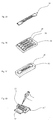
- FIG. 1B schematically shows an exemplary embodiment of a carrier 20 according to the invention in a plan view.
- 24 capillaries 1 are attached to the carrier at a uniform distance of approximately 4.5 mm in a common plane, the common plane here being parallel to or in the plane of the paper.
- the carrier essentially has two, preferably approximately parallel, fastening struts 21, 22.
- each capillary 1 is fastened to both fastening struts, ie each capillary is fastened to the carrier at least at two points 9, 10 which are in conflict with one another, as a result of which secure fastening is achieved becomes.
- the two fastening struts 21, 22 are preferably spaced apart from one another.
- the measurement gap / the measurement window 2 which enables light to be transmitted through the individual capillaries perpendicular to the common plane, is preferably located between the two fastening struts.
- the measuring gap / the measuring window 2 allows optical measurements, for example fluorescence measurements, preferably microsale thermophoresis measurements to be carried out.
- grip areas 3 serve on the one hand for gripping the carrier by a user and also firmly connect the two fastening struts to one another.
- the grip areas 3 can also be shaped or have appropriate devices so that automated gripping of the carrier is made possible or facilitated.
- reference number 4 provides a device or guide for automated gripping or guiding.
- the grip areas 3 also preferably have a labeling area 5, on which information can be applied by hand or by machine.
- the carrier is designed such that the capillaries from one side (in Figure 1B the right side, in Figure 1A the side facing the viewer) can be filled. These Side is also called the 'front' side.
- the opposite side of the carrier in Figure 1B the left side or in Figure 1A the invisible side facing away from the viewer) is also referred to as the "back" or “back” side.
- Appropriate terms are used in relation to the capillaries arranged in the carrier.
- the two ends of a capillary 1 are referred to below as the first free or front end 11 (right end in Figure 1B ) and as the second or rear end 12 (left end in Figure 1B ) designated.
- the first front ends preferably protrude approximately 11 mm above the carrier, more precisely from the front (right) fastening strut 22 of the carrier, so that these ends can simultaneously be inserted into cavities of a microtiter plate in such a way that filling of the capillaries is made possible (see for example Fig. 5-2a ).
- a common (front) line A (see Figure 1B ), whereby it can be achieved that the capillaries can be inserted equally far into the cavities of a microtiter plate.
- Line A is preferably parallel to a virtual connecting line between the upper front end of handle 3 and the lower front end of handle 3.
- Line A preferably lies on this virtual connecting line.
- the handle 3 in particular the front section or the front end of the handle 3 (right in Figure 1B ) serve as a stop, thereby ensuring, for example, that the front ends 11 of the capillaries 1 are immersed in a desired or predetermined immersion depth in the cavities of a microtiter plate, ie the handle 3 can function as a stop to prevent the front ends 11 the capillaries 1 against the bottom of the wells of a microtiter plate and thus not be damaged.
- the distance between the front ends 11 of the capillaries and the line A is 2mm.
- the front (right) fastening strut 22 of the carrier 20 can also serve as such a stop.
- the carrier preferably has a (rear) stop 13 against which the rear ends 12 of the capillaries can be aligned.
- the stop 13 is preferably provided on a third strut 23, which is provided, preferably approximately parallel to the struts 21, 22, further preferably in the region of the back of the carrier. Capillaries of the same length can thus be aligned on the stop 13, which preferably runs parallel to the fastening struts. It can thus advantageously be achieved that the first front ends 11 of the capillaries 1 lie on a common straight line (parallel to the dashed line A in Figure 1B ).
- a gap 6 is formed between the stop 13 or the rear strut 23 and the (left) rear fastening strut 21.
- This tempering gap 6 enables individual or joint tempering of the capillaries with the aid of, for example, tempered air (heated or cooled) which is passed through the tempering gap 6.
- a heat-conducting material can also be present in the temperature-regulating gap 6, which is temperature-controlled via temperature-regulating elements in the measuring device and is thermally conductively connected to the capillaries.
- the area between the web 22 and the capillary end 11 can also be used for the temperature control of the capillaries.
- the area between the webs 21 and 22 can also be used, for example, for the temperature control of the capillaries.
- the capillaries 1 In order to enable the capillaries 1 to be filled at the front end 11, there is preferably no fluid-tight contact between the stop 13 and the rear end 12 of the capillaries.
- a ventilation gap 7 As a result of which the air present in the capillaries can escape when the capillaries are filled.
- This gap can be achieved, for example, by providing a bevel 14 and / or step 15. This is exemplified in the schematic details of the Figures 1C and 1D shown.
- the venting gap can also be designed such that it consists of a narrow air gap between the stop 13 and the rear capillary end 12, for example the stop does not have to be oblique in this case.
- Each capillary 1 has its own inscription 8 on the stop, here on the strut 23 forming the stop.
- Figure 2 shows a perspective view of a corresponding carrier.
- Figure 2B shows the detail of a grip area 3 with a device or guide for automated gripping or guiding.
- This is preferably wedge-shaped here and has two surfaces 4a, 4b tapering toward one another, ie pointing away from the carrier.
- the device 4 preferably has front and / or rear stops 4c and 4d. These preferably run obliquely or inclined towards one another (wedge-shaped), in particular from the outside in the direction inwards or in the direction of the capillaries.
- An inner stop 4e that is to say arranged from the outside in the direction of the carrier or the capillaries, can also be provided.
- Two stops 4c, 4d and / or 4e are preferably provided, which are preferably arranged essentially symmetrically with respect to the wedge-shaped design of the surfaces 4a, 4b.
- Figure 2C shows a sectional view AA of a detail of the guide device 4 according to FIG Figure 2A .
- the carrier is preferably designed to be stackable.
- the carriers can lie on top of one another or be stacked without the capillaries being damaged or soiled. This can be made possible, for example, by a suitable 'thickening' of the carrier, for example in the area of the grip areas 3.
- stack elements are preferably provided (not shown) which, in addition to the sufficient spacing, allow positioning, for example.
- the carriers are designed such that the spacings of the corresponding capillaries 1 of two adjacent carriers in the stacked state, as described at the beginning, is approximately 4.5 mm or another multiple of 2.25 mm.
- the capillaries of the stacked carriers can preferably be immersed and filled at the same time.
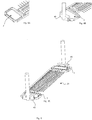
- FIGs 7A and 7B show a perspective view of an alternative embodiment of the carrier and a corresponding detail.
- This has a stop 13 'in the form of a recess or pocket, which can also be used in the other embodiments.
- the remaining features then correspond to those described in relation to the other embodiments.
- the capillaries 1 abut a rear stop, for example, as described above and, for example, in relation to FIG 1C and 1D explained or there is for example a narrow air gap between the capillary end 12 and stop 13 '.
- the capillaries 1 are additionally located in a pocket or recess, a pocket being preferably provided for each capillary.
- This embodiment preferably allows, in addition to the advantages already mentioned above, that not only air can escape from the capillary but that any additionally escaping liquid is collected and can preferably be drawn back into the capillary. This preferably prevents the emerging liquid from running from one capillary into neighboring capillaries. In this way, undesired 'cleaning' of the capillaries can preferably be made more difficult or even prevented.
- Figure 3A shows a further schematic perspective view of the carrier of FIG Figures 1 or 2A.
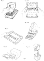
- Figure 3B is shown by way of example how several, here four, carriers 20 according to the invention are arranged in a tray 30 according to the invention.
- Figure 3C shows a further tray 30 'according to the invention, which is designed to receive a single carrier 20.
- the tray 30 or 30 ' is designed to receive one or more carriers 20.
- the tray preferably has one or more recesses and / or further mechanical means, such as, for example, projections or clamping devices. These are matched to the geometry of the carrier and preferably allow safe, non-slip positioning of the carrier (s) on the tray.
- Fig. 3D shows a filling station 30 'according to the invention with a carrier 20 according to the invention.
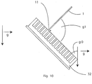
- the filling station 30 is preferably designed or aligned in order to achieve an inclined positioning of the carrier 20, for example at 45 ° to the horizontal. This can make manual filling easier, for example The preferred advantages of such tilting of the carrier 20 and / or the capillaries with respect to the gravitational force are discussed further below with respect to FIG Fig. 10 described in more detail.
- the filling station 30 ′′ is preferably designed to receive a multi-animal plate 32 and to arrange it in relation to the carrier. In this way, manual filling of the capillaries can be simplified.
- FIGS. 4A to 4D show examples of the mechanical attachment of individual capillaries 1 to the carrier according to the invention, but without being limited thereto.
- the Figure 4A on the left a capillary 1, which is attached to the carrier with the aid of a two-part clip.
- the two-part clip has two L-shaped elements 41, 42 which protrude substantially from the carrier and which fix the capillary 1 to the carrier.
- At least one of the elements 41, 42 is so flexible that the capillary can be pressed into the space 43 between the L-shaped elements, that is to say that at least one of the L-shaped elements 41, 42 flexibly deflects laterally outwards when the Capillary is pressed into the space and preferably springs back again when the capillary is in the space 43.
- This can preferably be supported by the provision of a bevel 44 on at least one of the elements 41, 42.
- Figure 4B shows a further embodiment of the invention for attaching the capillary 1 on the carrier by means of adhesive.
- a recess 44 or groove 44 is preferably formed in the carrier, which is used to hold adhesive 45 and / or the capillary 1.
- the depth of the recess is smaller than the diameter of the capillary, so that the stuck capillary protrudes above the carrier (upwards).
- Figure 4C shows a further embodiment according to the invention for fastening the capillary 1 on the carrier by means of embossing or hot stamping.
- at least one element 46 is preferably provided, which is plastically deformed after a capillary 1 has been placed or inserted, so that it fixes the capillary. This can preferably be done by means of a corresponding tool, for example a stamp 406, which can also be designed as a hot stamp.
- the fastening part 48 is preferably designed as an element separate from the carrier 10 and has an essentially angular or L-shaped shape. A U-shape or other geometries are also possible, for example.
- the carrier or web is provided with a corresponding receiving element, here an opening 49.
- the fastening part 48 can be attached to the receiving element 49 by positive and / or non-positive connection.
- the shape of the fastening part makes it possible to at least partially encompass an inserted or placed capillary and thus to fix it to the carrier.
- the fastening means are preferably designed in such a way that, if necessary together with the web, they essentially enclose the individual capillaries along their circumference.
- a barrier can preferably be formed which prevents liquid that has reached the outside of the capillaries from entering the measuring region when the capillaries are filled.
- the barrier can be mechanical (almost completely enclosing) and / or physical (only a small gap or free space so that, for example due to the surface tension, no liquid penetrates within the usage times, for example up to 5 days).
- Figure 5 shows preferred process steps for filling carriers according to the invention and the use of carriers and trays according to the invention.
- a multiwell plate filled with sample liquid As is also known in the prior art, this is preferably done by a filling robot.
- the capillaries arranged in the carrier according to the invention are filled. This is done, for example, by simultaneously immersing all capillaries of at least one support in wells or depressions in the microtiter plate according to step 5-2a.
- a stacked arrangement of several carriers, as described above, enables the capillaries of several carriers to be filled simultaneously.
- the carrier is advantageously designed and / or dimensioned such that positioning of the carrier and thus the capillaries relative to the microtiter plate is facilitated, for example by predetermined stops, for example the grip areas 3, on the microtiter plate.
- An adapter or a filling aid can preferably also be provided in Figure 5-2a shown schematically, which supports and facilitates immersion and filling of the capillaries.
- the carrier according to the invention thus allows a semi-automatic, simultaneous filling of a large number of capillaries, for example 24 capillaries.
- the filling aid or filling aid preferably prevents damage to the capillaries.
- the filling aid is preferably designed such that the capillaries and the microtiter plate are preferably aligned at a specific angle relative to the direction of gravitation in order to support the filling of the capillaries.
- the tilting of the microtiter plate 32 and the capillaries 1 with respect to the gravitational force is illustrated, for example, in FIG Fig. 10 .
- the microtitre plate and / or the capillary are preferably oriented at angles of approximately 0 °, approximately 30 °, approximately 45 °, approximately 60 ° approximately 90 ° or approximately 180 ° with respect to the gravitational force g.
- This alignment / tilting is preferably carried out by the filling aid in such a way that the longitudinal axis of the capillaries is essentially perpendicular (see angle g1) on the bottom plane / base area of the microtiter plate.
- the microtiter plate is aligned by the filling aid so that its base / bottom surface is aligned at an angle of 30 ° to the direction of gravity (see angle g0); in this case, the capillaries / capillary carriers are preferably aligned by the filling aid so that they unite Form an angle of 60 ° to the direction of gravity.
- the microtiter plate 32 and capillaries 1 are preferably aligned with one another by the filling aid in such a way that the capillaries are prevented from breaking off when immersed in the microtiter plate.
- the microtiter plate is preferably aligned with respect to the capillaries in such a way that the longitudinal axis of the capillaries are aligned parallel to the walls of the cavities in the microtiter plate. This inclination relative to the direction of gravitation preferably facilitates the filling of the capillaries, since the capillary forces do not have to work against the full gravitational forces when inclined ("inclined plane" principle).
- the inclination of the microtiter plates and the capillaries can depend on the liquid to be drawn in; for example, in the case of liquids with a large number of detergents, the microtiter plate can be oriented at a larger angle relative to the direction of gravity in order to prevent the liquids from escaping from the cavities.
- the bottom plane / base area of the microtiter plate can be oriented at an angle of 0 ° relative to gravitation or, for example, also at an angle of 180 ° to gravitation (microtiter plate is upside down) in order to fill the capillaries with very viscous liquids or liquids to ensure low capillary forces occur
- the capillaries can be filled by pipetting, for example in connection with Figure 3D or 5-2b describe.
- the carrier according to the invention proves to be particularly advantageous here because it ensures safe filling, in particular by suitable ones Alignment and arrangement of the capillaries enables.
- the simultaneous filling of a large number of capillaries is advantageously made possible here.
- the carrier according to the invention allows the capillaries to be filled automatically.
- the carrier or carriers are placed or positioned on a tray according to the invention. Then the tray with the carrier (s) is placed in an analyzer, step 5-4. Depending on the design of the analyzer, the carriers can also be inserted directly, i.e. without a tray. However, the use of a tray proves to be advantageous, particularly with regard to handling and process reliability.
- the tray is removed from the analysis device, possibly stored temporarily, for example for later comparison measurements, and then emptied, step 5-5.
- the tray can then be reused.
- the carriers are preferably disposed of.
- FIG 6B schematically shows an exemplary embodiment of a carrier 20 'according to the invention in a plan view, Figure 6A in the side view.
- the carrier 20 ' essentially corresponds to that in connection with FIG Figures 1 and 2nd described. Therefore, only the differences will be dealt with below, wherein different features between the embodiments can preferably also be provided in the respective other embodiment.
- the pocket-shaped stop 13 'according to the embodiment according to Figures 6 and 7 as already described above, also in the embodiment according to Figures 1 and 2nd be provided.
- the features described below, individually or in combination can also be provided in the other embodiments or can be replaced or supplemented by the features provided in other embodiments.
- the carrier according to Fig. 6 preferably has at least one opening or opening or depression 25. As shown, preferably two.
- the openings 25 are preferably elongated and extend approximately parallel to the capillaries 1.
- the openings 25 are preferably arranged between the grip area 3 and the capillaries 1. They can be delimited by the grip area 3, the webs 21, 22, and / or 23 and, if appropriate, a further delimitation web 27 which is essentially transverse to the webs 21, 22, and / or 23 extends and is preferably arranged between the opening 25 and the capillaries 1.
- the breakthrough preferably allows the exact positioning and alignment of the carrier, for example in the case of semi-automatic or automatic filling and / or when arranging on a tray according to the invention.
- Exactly matched domes reach into these openings, which means that the wearer can be positioned or aligned exactly.
- Such domes or projections can be provided on a filling aid, a tray and / or a gripper of a robot / handling device.
- the openings allow a guide element, for example a cylindrical bolt (not shown), to engage therein. This means that the array can only be moved around the area or along the free opening (see arrow in Figure 6B ).
- a guide element can be provided on a filling aid and / or a gripper of a robot / handling device.
- the openings thus advantageously allow guidance and / or positioning in the longitudinal direction of the capillaries arranged on the carrier and / or in the transverse direction of the capillaries in their arrangement plane.
- the opening is preferably not designed as a continuous opening but as a depression.
- the capillaries can also be permitted.
- at least 1, 2 or 4 openings 25 can be provided. If more than two openings formed as recesses are provided, two openings can be arranged on opposite sides of a grip area 3. In this way, advantageous, multidimensional guidance and / or positioning can be achieved.
- the carriers according to the invention preferably have devices / gripping surfaces 4 which allow the carrier to be handled automatically, for example with pipetting robots or other automatic devices / grippers. This means that the entire filling process can be fully automated.
- a preferred embodiment of the guiding or gripping devices 4 has already been described above.
- Devices 4 of this type particularly facilitate gripping by means of a handling device, for example. They are preferably arranged on opposite outer sides of the carrier, preferably on long sides (sides extending transversely to the longitudinal axis) of the outwardly facing side of the grip areas 3.
- the person skilled in the art will be familiar with the fact that other positions are also possible.
- the gripping devices are shaped in this way or in particular allow the array to be positioned securely and centered in a gripper.
- the wedge-shaped surfaces 4a, 4b, 4c, 4d can support automatic alignment or automatic centering in the horizontal and vertical axes. Even if the array is not packed tightly, it cannot easily fall out of the grippers (tolerance allowance).
- the gripping devices also allow the carrier to be gripped from a stack of carriers, from a package, from a surface or from a device. It is only necessary here that there is enough space on the narrow sides for the grippers to be able to engage the gripping devices.
- the gripping devices are preferably designed so that they can be gripped with a combined gripper that can carry out various handling steps.
- Figure 8 shows an example of a corresponding gripper of a robot or handling system, which is designed with a geometry corresponding to the gripping device and is in engagement with it.
- the gripper preferably has surfaces corresponding to the surfaces 4a, 4b, 4c, 4d and 4e, which can be brought into engagement with them, in particular in order to enable safe gripping and safe positioning and handling.
- Figure 8 a schematic perspective example of automated handling branches, whereby Figure 8A one end of a carrier with a grip area 3 shows and Figure 8B this end with a gripper of a handling system, which is in engagement with the gripping device 4 of the grip area 3.
- Figure 8C shows a complete view of the carrier with grippers engaged.
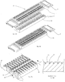
- FIG. 9A shows an example of a temperature control device for temperature control of the capillaries 1 of a carrier 20.
- the perspective view shows the carrier before the temperature control separately from the temperature control device.
- the temperature control device has a temperature control body 50 with temperature control ribs 55 spaced apart from one another. Recesses 51 are formed between the temperature control ribs and serve to receive the capillaries 1 (see 9B, 9C and 9D).
- Figure 9B shows a carrier 20 which lies on the temperature control body such that at least one, preferably more, of the temperature control ribs 55 lie between the capillaries.
- the capillaries are located in the corresponding cutouts 51.
- the temperature control device preferably has at least one row with temperature ribs, preferably two rows of temperature ribs, as in FIGS Figures 9A to 9C shown.
- the first row of temperature-control ribs 55 is preferably designed such that they are arranged between the capillaries 1 in front of the front web 22 (front fastening strut) of the carrier 20 when the carrier is placed in the temperature-control device for temperature control.
- a second row of temperature-regulating ribs 55 is designed such that it lies between the capillaries 1 and behind the central web 21 (central fastening strut), preferably between the web 21 and the third strut 23, when the carrier is for tempering in the temperature control device is placed.
- the temperature-control ribs preferably lie in the temperature-control region 6 of the carrier during the temperature control, a carrier preferably having two temperature-control regions, which preferably enable individual or joint temperature control of one or more capillaries.
- a first temperature control region 6 of the carrier is preferably formed between one of the two webs 21, 22 and the rear web 23 and / or between one of the two webs 21, 22 and the free end (11).
- the capillaries are preferably heated / cooled / tempered by a temperature-controlled air cushion between the temperature-control ribs and the cover (not shown).
- the cover is preferably designed such that it completely covers the carrier and the capillaries and preferably has an opening in the area of the measuring area 2.
- a sequence in which a handling device is integrated can be represented as follows, the individual steps being optional: 0.
- the packaging is opened by the gripper. 1. Removing an array from the packaging / magazine 2. Transporting the array to a filling position 3. Filling the array 4. Transporting the filled array to a tray / measuring device 5. Placing (and positioning) on the tray / in the measuring device 6 After the measuring process: remove the array / tray from the measuring device and transport it to a storage container (eg garbage box or intermediate storage).
- a storage container eg garbage box or intermediate storage
- the invention also includes the exact or exact terms, features, numerical values or ranges, etc., if above or below these terms, features, numerical values or ranges in connection with terms such as e.g. “approximately, approximately, um, essentially, generally, at least, at least” etc. (ie “approximately 3” should also include “3” or “substantially radial” should also include “radial”).
- the expression “or” also means “and / or”.
Landscapes
- Health & Medical Sciences (AREA)
- Chemical & Material Sciences (AREA)
- General Health & Medical Sciences (AREA)
- General Physics & Mathematics (AREA)
- Physics & Mathematics (AREA)
- Life Sciences & Earth Sciences (AREA)
- Analytical Chemistry (AREA)
- Biochemistry (AREA)
- Pathology (AREA)
- Immunology (AREA)
- Chemical Kinetics & Catalysis (AREA)
- Clinical Laboratory Science (AREA)
- Nuclear Medicine, Radiotherapy & Molecular Imaging (AREA)
- Optical Measuring Cells (AREA)
- Automatic Analysis And Handling Materials Therefor (AREA)
- Investigating, Analyzing Materials By Fluorescence Or Luminescence (AREA)
Priority Applications (7)
| Application Number | Priority Date | Filing Date | Title |
|---|---|---|---|
| DK13184379.9T DK2848309T3 (da) | 2013-09-13 | 2013-09-13 | Bærer til kapillarrør |
| EP13184379.9A EP2848309B1 (de) | 2013-09-13 | 2013-09-13 | Träger für kapillaren |
| ES14184674T ES2780362T3 (es) | 2013-09-13 | 2014-09-12 | Soporte para capilares |
| PL14184674T PL2848310T3 (pl) | 2013-09-13 | 2014-09-12 | Uchwyt dla kapilar |
| US14/484,640 US10488326B2 (en) | 2013-09-13 | 2014-09-12 | Capillary array |
| EP14184674.1A EP2848310B1 (de) | 2013-09-13 | 2014-09-12 | Träger für Kapillaren |
| DK14184674.1T DK2848310T3 (da) | 2013-09-13 | 2014-09-12 | Bærer til kapillarrør |
Applications Claiming Priority (1)
| Application Number | Priority Date | Filing Date | Title |
|---|---|---|---|
| EP13184379.9A EP2848309B1 (de) | 2013-09-13 | 2013-09-13 | Träger für kapillaren |
Publications (2)
| Publication Number | Publication Date |
|---|---|
| EP2848309A1 EP2848309A1 (de) | 2015-03-18 |
| EP2848309B1 true EP2848309B1 (de) | 2020-06-10 |
Family
ID=49162057
Family Applications (2)
| Application Number | Title | Priority Date | Filing Date |
|---|---|---|---|
| EP13184379.9A Active EP2848309B1 (de) | 2013-09-13 | 2013-09-13 | Träger für kapillaren |
| EP14184674.1A Active EP2848310B1 (de) | 2013-09-13 | 2014-09-12 | Träger für Kapillaren |
Family Applications After (1)
| Application Number | Title | Priority Date | Filing Date |
|---|---|---|---|
| EP14184674.1A Active EP2848310B1 (de) | 2013-09-13 | 2014-09-12 | Träger für Kapillaren |
Country Status (5)
| Country | Link |
|---|---|
| US (1) | US10488326B2 (pl) |
| EP (2) | EP2848309B1 (pl) |
| DK (2) | DK2848309T3 (pl) |
| ES (1) | ES2780362T3 (pl) |
| PL (1) | PL2848310T3 (pl) |
Families Citing this family (5)
| Publication number | Priority date | Publication date | Assignee | Title |
|---|---|---|---|---|
| DE102014018535A1 (de) * | 2014-12-12 | 2016-06-16 | Nanotemper Technologies Gmbh | System und Verfahren für ein abdichtungsfreies Temperieren von Kapillaren |
| EP3150988B1 (de) * | 2015-10-01 | 2021-01-27 | NanoTemper Technologies GmbH | System und verfahren für die optische messung der stabilität und der aggregation von partikeln |
| CN110160835A (zh) * | 2019-05-24 | 2019-08-23 | 深圳市前海微升科学股份有限公司 | 一种定量微量取样和传输的方法及其装置 |
| CN112295628A (zh) * | 2019-08-01 | 2021-02-02 | 利多(香港)有限公司 | 试剂的保存方法 |
| DE102021122449A1 (de) | 2021-08-31 | 2023-03-02 | Alfred-Wegener-Institut, Helmholtz-Zentrum für Polar- und Meeresforschung, Stiftung des öffentlichen Rechts | Halter für ein Kapillarröhrchen und Sammelvorrichtung für mehrere Halter |
Family Cites Families (11)
| Publication number | Priority date | Publication date | Assignee | Title |
|---|---|---|---|---|
| US4090920A (en) * | 1976-02-19 | 1978-05-23 | Fisher Scientific Company | Disposable antibiotic susceptability test package |
| WO2001021310A2 (en) * | 1999-09-21 | 2001-03-29 | Genome Therapeutics Corporation | Device for rapid dna sample processing with integrated liquid handling, thermocycling, and purification |
| AU2003217369A1 (en) * | 2002-02-08 | 2003-09-02 | Amersham Biosciences (Sv) Corporation | Method and apparatus for performing submicroliter reactions with nucleic acids or proteins |
| US20030165409A1 (en) * | 2002-03-04 | 2003-09-04 | Polymicro Technologies, Llc | Device and method for manipulating or dispensing multiple filaments |
| DE10251722A1 (de) * | 2002-11-06 | 2004-05-27 | Fraunhofer-Gesellschaft zur Förderung der angewandten Forschung e.V. | Träger für eine Probenkammer, insbesondere zur Kryokonservierung biologischer Proben |
| US20050186122A1 (en) * | 2004-02-20 | 2005-08-25 | Mercer James D. | Molded container |
| GB2422658A (en) * | 2005-01-31 | 2006-08-02 | Titude Ltd 4 | A method of flushing gas into an out of a sealable enclosure |
| EP1695762A3 (en) * | 2005-02-02 | 2007-03-28 | Agilent Technologies, Inc. | Common carrier for loading capillary vessels |
| WO2010033604A2 (en) * | 2008-09-18 | 2010-03-25 | X-Bar Diagnostic System, Inc. | Fully automated portable dna detection system |
| EP2572787B1 (en) | 2011-09-23 | 2020-05-27 | Nano Temper Technologies GmbH | Capillary for detecting properties of chemical and/or biological fluids |
| DE102011054998B4 (de) * | 2011-11-02 | 2013-06-27 | BAM Bundesanstalt für Materialforschung und -prüfung | Aufbewahrungs- und Transportbox für Glaskapillaren mit Probenmaterial |
-
2013
- 2013-09-13 DK DK13184379.9T patent/DK2848309T3/da active
- 2013-09-13 EP EP13184379.9A patent/EP2848309B1/de active Active
-
2014
- 2014-09-12 EP EP14184674.1A patent/EP2848310B1/de active Active
- 2014-09-12 DK DK14184674.1T patent/DK2848310T3/da active
- 2014-09-12 PL PL14184674T patent/PL2848310T3/pl unknown
- 2014-09-12 US US14/484,640 patent/US10488326B2/en active Active
- 2014-09-12 ES ES14184674T patent/ES2780362T3/es active Active
Non-Patent Citations (1)
| Title |
|---|
| 96 ET AL: "Corning Life Sciences Microplate Dimensions for Corning 96 Well Microplates", 360 10.67 6.86 / 4.57 127, 13 March 2009 (2009-03-13), pages 85 - 85, XP055328708, Retrieved from the Internet <URL:http://www.level.com.tw/html/ezcatfiles/vipweb20/img/img/20297/MD_Microplate_Dimension_Sheets_96_Well.pdf> [retrieved on 20161213] * |
Also Published As
| Publication number | Publication date |
|---|---|
| DK2848310T3 (da) | 2020-03-23 |
| DK2848309T3 (da) | 2020-09-07 |
| EP2848310A1 (de) | 2015-03-18 |
| EP2848310B1 (de) | 2020-01-15 |
| EP2848309A1 (de) | 2015-03-18 |
| PL2848310T3 (pl) | 2020-06-29 |
| US20150137005A1 (en) | 2015-05-21 |
| US10488326B2 (en) | 2019-11-26 |
| ES2780362T3 (es) | 2020-08-25 |
Similar Documents
| Publication | Publication Date | Title |
|---|---|---|
| EP2848310B1 (de) | Träger für Kapillaren | |
| DE19941905C2 (de) | Probenkammer zur Flüssigkeitsbehandlung biologischer Proben | |
| EP2257783B1 (de) | Küvette und verfahren zur optischen untersuchung kleiner flüssigkeitsmengen | |
| EP1353753B1 (de) | Haltevorrichtung | |
| DE19948087B4 (de) | Verfahren zur Herstellung eines Reaktionssubstrats | |
| EP0648536A1 (de) | Mehrgefässanordnung zur Instrumental-Analyse | |
| DE19933458A1 (de) | Einrichtung zum Handhaben von Flüssigkeitsproben, System zum Handhaben von Flüssigkeitsproben und Verfahren zum Herstellen der Einrichtung | |
| AT500523A1 (de) | Vorrichtung zur proteinkristallisation | |
| EP2599548B1 (de) | Probenträger zum Positionieren einer organischen, biologischen und/oder medizinischen Probe | |
| EP2169383A1 (de) | Körper für Durchflussküvetten und deren Verwendung | |
| WO2011036289A1 (de) | Flachkörper nach art einer chip-karte zur biochemischen analyse und verfahren zu dessen verwendung | |
| EP2656918B1 (de) | Kit | |
| EP4091715A1 (de) | Teststreifenanordnung mit behältern | |
| DE60005023T2 (de) | Analysevorrichtung mit einem biochip | |
| DE4016617A1 (de) | Objekttraeger fuer nasse oder feuchte praeparate, z. b. blut | |
| EP1815910A2 (en) | Disposable vessels or tips having ultra-thin areas therein, and methods for manufacture of same | |
| WO2006024392A2 (de) | Aufnahmeeinheit für biologische objekte sowie verfahren und vorrichtung zur verarbeitung in der aufnahmeeinheit aufgenommener biologischer objekte | |
| DE10117723A1 (de) | Probenträger, insbesondere für biochemische Reaktionen | |
| DE102018131123A1 (de) | Deckel für eine Mikrotiterplatte | |
| DE202022103803U1 (de) | Mikroplatten-Adapter | |
| DE10058690C1 (de) | Objektträgersystem für die Labordiagnostik und Mikroskopie | |
| EP4714546A1 (de) | Vorrichtung zur aufnahme von proben-gefässen und kit umfassend eine vorrichtung zur aufnahme von proben-gefässen | |
| AT500167B1 (de) | Reaktionsgefäss | |
| WO2003106032A1 (de) | Hybridisierungskammer | |
| DE10318219A1 (de) | Handhabungs- und Schutzgehäuse für einen Biochip, insbesondere für einen mikrofluidischen Reaktionsträger |
Legal Events
| Date | Code | Title | Description |
|---|---|---|---|
| PUAI | Public reference made under article 153(3) epc to a published international application that has entered the european phase |
Free format text: ORIGINAL CODE: 0009012 |
|
| 17P | Request for examination filed |
Effective date: 20130913 |
|
| AK | Designated contracting states |
Kind code of ref document: A1 Designated state(s): AL AT BE BG CH CY CZ DE DK EE ES FI FR GB GR HR HU IE IS IT LI LT LU LV MC MK MT NL NO PL PT RO RS SE SI SK SM TR |
|
| AX | Request for extension of the european patent |
Extension state: BA ME |
|
| R17P | Request for examination filed (corrected) |
Effective date: 20150918 |
|
| RBV | Designated contracting states (corrected) |
Designated state(s): AL AT BE BG CH CY CZ DE DK EE ES FI FR GB GR HR HU IE IS IT LI LT LU LV MC MK MT NL NO PL PT RO RS SE SI SK SM TR |
|
| STAA | Information on the status of an ep patent application or granted ep patent |
Free format text: STATUS: EXAMINATION IS IN PROGRESS |
|
| 17Q | First examination report despatched |
Effective date: 20161220 |
|
| GRAP | Despatch of communication of intention to grant a patent |
Free format text: ORIGINAL CODE: EPIDOSNIGR1 |
|
| STAA | Information on the status of an ep patent application or granted ep patent |
Free format text: STATUS: GRANT OF PATENT IS INTENDED |
|
| INTG | Intention to grant announced |
Effective date: 20200102 |
|
| GRAS | Grant fee paid |
Free format text: ORIGINAL CODE: EPIDOSNIGR3 |
|
| GRAA | (expected) grant |
Free format text: ORIGINAL CODE: 0009210 |
|
| STAA | Information on the status of an ep patent application or granted ep patent |
Free format text: STATUS: THE PATENT HAS BEEN GRANTED |
|
| AK | Designated contracting states |
Kind code of ref document: B1 Designated state(s): AL AT BE BG CH CY CZ DE DK EE ES FI FR GB GR HR HU IE IS IT LI LT LU LV MC MK MT NL NO PL PT RO RS SE SI SK SM TR |
|
| REG | Reference to a national code |
Ref country code: GB Ref legal event code: FG4D Free format text: NOT ENGLISH |
|
| REG | Reference to a national code |
Ref country code: CH Ref legal event code: EP Ref country code: AT Ref legal event code: REF Ref document number: 1278776 Country of ref document: AT Kind code of ref document: T Effective date: 20200615 |
|
| REG | Reference to a national code |
Ref country code: DE Ref legal event code: R096 Ref document number: 502013014782 Country of ref document: DE |
|
| REG | Reference to a national code |
Ref country code: IE Ref legal event code: FG4D Free format text: LANGUAGE OF EP DOCUMENT: GERMAN |
|
| REG | Reference to a national code |
Ref country code: NL Ref legal event code: FP |
|
| REG | Reference to a national code |
Ref country code: DK Ref legal event code: T3 Effective date: 20200902 |
|
| REG | Reference to a national code |
Ref country code: SE Ref legal event code: TRGR |
|
| REG | Reference to a national code |
Ref country code: CH Ref legal event code: NV Representative=s name: VOSSIUS AND PARTNER PATENTANWAELTE RECHTSANWAE, CH |
|
| REG | Reference to a national code |
Ref country code: LT Ref legal event code: MG4D |
|
| PG25 | Lapsed in a contracting state [announced via postgrant information from national office to epo] |
Ref country code: FI Free format text: LAPSE BECAUSE OF FAILURE TO SUBMIT A TRANSLATION OF THE DESCRIPTION OR TO PAY THE FEE WITHIN THE PRESCRIBED TIME-LIMIT Effective date: 20200610 Ref country code: LT Free format text: LAPSE BECAUSE OF FAILURE TO SUBMIT A TRANSLATION OF THE DESCRIPTION OR TO PAY THE FEE WITHIN THE PRESCRIBED TIME-LIMIT Effective date: 20200610 Ref country code: NO Free format text: LAPSE BECAUSE OF FAILURE TO SUBMIT A TRANSLATION OF THE DESCRIPTION OR TO PAY THE FEE WITHIN THE PRESCRIBED TIME-LIMIT Effective date: 20200910 Ref country code: GR Free format text: LAPSE BECAUSE OF FAILURE TO SUBMIT A TRANSLATION OF THE DESCRIPTION OR TO PAY THE FEE WITHIN THE PRESCRIBED TIME-LIMIT Effective date: 20200911 |
|
| PG25 | Lapsed in a contracting state [announced via postgrant information from national office to epo] |
Ref country code: RS Free format text: LAPSE BECAUSE OF FAILURE TO SUBMIT A TRANSLATION OF THE DESCRIPTION OR TO PAY THE FEE WITHIN THE PRESCRIBED TIME-LIMIT Effective date: 20200610 Ref country code: BG Free format text: LAPSE BECAUSE OF FAILURE TO SUBMIT A TRANSLATION OF THE DESCRIPTION OR TO PAY THE FEE WITHIN THE PRESCRIBED TIME-LIMIT Effective date: 20200910 Ref country code: LV Free format text: LAPSE BECAUSE OF FAILURE TO SUBMIT A TRANSLATION OF THE DESCRIPTION OR TO PAY THE FEE WITHIN THE PRESCRIBED TIME-LIMIT Effective date: 20200610 Ref country code: HR Free format text: LAPSE BECAUSE OF FAILURE TO SUBMIT A TRANSLATION OF THE DESCRIPTION OR TO PAY THE FEE WITHIN THE PRESCRIBED TIME-LIMIT Effective date: 20200610 |
|
| PG25 | Lapsed in a contracting state [announced via postgrant information from national office to epo] |
Ref country code: AL Free format text: LAPSE BECAUSE OF FAILURE TO SUBMIT A TRANSLATION OF THE DESCRIPTION OR TO PAY THE FEE WITHIN THE PRESCRIBED TIME-LIMIT Effective date: 20200610 |
|
| PG25 | Lapsed in a contracting state [announced via postgrant information from national office to epo] |
Ref country code: EE Free format text: LAPSE BECAUSE OF FAILURE TO SUBMIT A TRANSLATION OF THE DESCRIPTION OR TO PAY THE FEE WITHIN THE PRESCRIBED TIME-LIMIT Effective date: 20200610 Ref country code: SM Free format text: LAPSE BECAUSE OF FAILURE TO SUBMIT A TRANSLATION OF THE DESCRIPTION OR TO PAY THE FEE WITHIN THE PRESCRIBED TIME-LIMIT Effective date: 20200610 Ref country code: RO Free format text: LAPSE BECAUSE OF FAILURE TO SUBMIT A TRANSLATION OF THE DESCRIPTION OR TO PAY THE FEE WITHIN THE PRESCRIBED TIME-LIMIT Effective date: 20200610 Ref country code: CZ Free format text: LAPSE BECAUSE OF FAILURE TO SUBMIT A TRANSLATION OF THE DESCRIPTION OR TO PAY THE FEE WITHIN THE PRESCRIBED TIME-LIMIT Effective date: 20200610 Ref country code: ES Free format text: LAPSE BECAUSE OF FAILURE TO SUBMIT A TRANSLATION OF THE DESCRIPTION OR TO PAY THE FEE WITHIN THE PRESCRIBED TIME-LIMIT Effective date: 20200610 Ref country code: PT Free format text: LAPSE BECAUSE OF FAILURE TO SUBMIT A TRANSLATION OF THE DESCRIPTION OR TO PAY THE FEE WITHIN THE PRESCRIBED TIME-LIMIT Effective date: 20201012 |
|
| PG25 | Lapsed in a contracting state [announced via postgrant information from national office to epo] |
Ref country code: PL Free format text: LAPSE BECAUSE OF FAILURE TO SUBMIT A TRANSLATION OF THE DESCRIPTION OR TO PAY THE FEE WITHIN THE PRESCRIBED TIME-LIMIT Effective date: 20200610 Ref country code: SK Free format text: LAPSE BECAUSE OF FAILURE TO SUBMIT A TRANSLATION OF THE DESCRIPTION OR TO PAY THE FEE WITHIN THE PRESCRIBED TIME-LIMIT Effective date: 20200610 Ref country code: IS Free format text: LAPSE BECAUSE OF FAILURE TO SUBMIT A TRANSLATION OF THE DESCRIPTION OR TO PAY THE FEE WITHIN THE PRESCRIBED TIME-LIMIT Effective date: 20201010 |
|
| REG | Reference to a national code |
Ref country code: DE Ref legal event code: R097 Ref document number: 502013014782 Country of ref document: DE |
|
| PLBE | No opposition filed within time limit |
Free format text: ORIGINAL CODE: 0009261 |
|
| STAA | Information on the status of an ep patent application or granted ep patent |
Free format text: STATUS: NO OPPOSITION FILED WITHIN TIME LIMIT |
|
| PG25 | Lapsed in a contracting state [announced via postgrant information from national office to epo] |
Ref country code: MC Free format text: LAPSE BECAUSE OF FAILURE TO SUBMIT A TRANSLATION OF THE DESCRIPTION OR TO PAY THE FEE WITHIN THE PRESCRIBED TIME-LIMIT Effective date: 20200610 |
|
| 26N | No opposition filed |
Effective date: 20210311 |
|
| PG25 | Lapsed in a contracting state [announced via postgrant information from national office to epo] |
Ref country code: SI Free format text: LAPSE BECAUSE OF FAILURE TO SUBMIT A TRANSLATION OF THE DESCRIPTION OR TO PAY THE FEE WITHIN THE PRESCRIBED TIME-LIMIT Effective date: 20200610 |
|
| PG25 | Lapsed in a contracting state [announced via postgrant information from national office to epo] |
Ref country code: LU Free format text: LAPSE BECAUSE OF NON-PAYMENT OF DUE FEES Effective date: 20200913 |
|
| PG25 | Lapsed in a contracting state [announced via postgrant information from national office to epo] |
Ref country code: IE Free format text: LAPSE BECAUSE OF NON-PAYMENT OF DUE FEES Effective date: 20200913 |
|
| PG25 | Lapsed in a contracting state [announced via postgrant information from national office to epo] |
Ref country code: TR Free format text: LAPSE BECAUSE OF FAILURE TO SUBMIT A TRANSLATION OF THE DESCRIPTION OR TO PAY THE FEE WITHIN THE PRESCRIBED TIME-LIMIT Effective date: 20200610 Ref country code: MT Free format text: LAPSE BECAUSE OF FAILURE TO SUBMIT A TRANSLATION OF THE DESCRIPTION OR TO PAY THE FEE WITHIN THE PRESCRIBED TIME-LIMIT Effective date: 20200610 Ref country code: CY Free format text: LAPSE BECAUSE OF FAILURE TO SUBMIT A TRANSLATION OF THE DESCRIPTION OR TO PAY THE FEE WITHIN THE PRESCRIBED TIME-LIMIT Effective date: 20200610 |
|
| PG25 | Lapsed in a contracting state [announced via postgrant information from national office to epo] |
Ref country code: MK Free format text: LAPSE BECAUSE OF FAILURE TO SUBMIT A TRANSLATION OF THE DESCRIPTION OR TO PAY THE FEE WITHIN THE PRESCRIBED TIME-LIMIT Effective date: 20200610 |
|
| PGFP | Annual fee paid to national office [announced via postgrant information from national office to epo] |
Ref country code: DK Payment date: 20240918 Year of fee payment: 12 |
|
| PGFP | Annual fee paid to national office [announced via postgrant information from national office to epo] |
Ref country code: GB Payment date: 20240925 Year of fee payment: 12 |
|
| PGFP | Annual fee paid to national office [announced via postgrant information from national office to epo] |
Ref country code: BE Payment date: 20240911 Year of fee payment: 12 |
|
| PGFP | Annual fee paid to national office [announced via postgrant information from national office to epo] |
Ref country code: FR Payment date: 20240909 Year of fee payment: 12 |
|
| PGFP | Annual fee paid to national office [announced via postgrant information from national office to epo] |
Ref country code: NL Payment date: 20240911 Year of fee payment: 12 |
|
| PGFP | Annual fee paid to national office [announced via postgrant information from national office to epo] |
Ref country code: AT Payment date: 20240904 Year of fee payment: 12 |
|
| PGFP | Annual fee paid to national office [announced via postgrant information from national office to epo] |
Ref country code: IT Payment date: 20240916 Year of fee payment: 12 Ref country code: SE Payment date: 20240913 Year of fee payment: 12 |
|
| PGFP | Annual fee paid to national office [announced via postgrant information from national office to epo] |
Ref country code: DE Payment date: 20240930 Year of fee payment: 12 |
|
| PGFP | Annual fee paid to national office [announced via postgrant information from national office to epo] |
Ref country code: CH Payment date: 20241001 Year of fee payment: 12 |
|
| REG | Reference to a national code |
Ref country code: DK Ref legal event code: EBP Effective date: 20250930 |
|
| REG | Reference to a national code |
Ref country code: CH Ref legal event code: H13 Free format text: ST27 STATUS EVENT CODE: U-0-0-H10-H13 (AS PROVIDED BY THE NATIONAL OFFICE) Effective date: 20260504 |
|
| REG | Reference to a national code |
Ref country code: NL Ref legal event code: MM Effective date: 20251001 |