EP2848098B1 - Exchangeable cathode interface for a plasma spray gun and method of making a plasma spray gun with the same - Google Patents
Exchangeable cathode interface for a plasma spray gun and method of making a plasma spray gun with the same Download PDFInfo
- Publication number
- EP2848098B1 EP2848098B1 EP13787759.3A EP13787759A EP2848098B1 EP 2848098 B1 EP2848098 B1 EP 2848098B1 EP 13787759 A EP13787759 A EP 13787759A EP 2848098 B1 EP2848098 B1 EP 2848098B1
- Authority
- EP
- European Patent Office
- Prior art keywords
- interface
- cathode
- connecting section
- interchangeable
- annular
- Prior art date
- Legal status (The legal status is an assumption and is not a legal conclusion. Google has not performed a legal analysis and makes no representation as to the accuracy of the status listed.)
- Active
Links
- 239000007921 spray Substances 0.000 title claims description 15
- 238000004519 manufacturing process Methods 0.000 title claims description 3
- 230000008878 coupling Effects 0.000 claims description 17
- 238000010168 coupling process Methods 0.000 claims description 17
- 238000005859 coupling reaction Methods 0.000 claims description 17
- 239000012809 cooling fluid Substances 0.000 claims description 11
- 238000001816 cooling Methods 0.000 claims description 10
- 238000007789 sealing Methods 0.000 claims description 8
- 238000010891 electric arc Methods 0.000 claims description 5
- 238000000576 coating method Methods 0.000 description 7
- 239000000463 material Substances 0.000 description 6
- 238000000034 method Methods 0.000 description 5
- 238000005507 spraying Methods 0.000 description 5
- 239000011248 coating agent Substances 0.000 description 4
- 230000008569 process Effects 0.000 description 4
- 230000008901 benefit Effects 0.000 description 3
- 230000006872 improvement Effects 0.000 description 3
- 238000007750 plasma spraying Methods 0.000 description 3
- XLYOFNOQVPJJNP-UHFFFAOYSA-N water Substances O XLYOFNOQVPJJNP-UHFFFAOYSA-N 0.000 description 3
- 230000009286 beneficial effect Effects 0.000 description 1
- 239000002826 coolant Substances 0.000 description 1
- 230000007797 corrosion Effects 0.000 description 1
- 238000005260 corrosion Methods 0.000 description 1
- 230000007812 deficiency Effects 0.000 description 1
- 230000001419 dependent effect Effects 0.000 description 1
- 238000009434 installation Methods 0.000 description 1
- 230000013011 mating Effects 0.000 description 1
- 238000013021 overheating Methods 0.000 description 1
- 239000002245 particle Substances 0.000 description 1
- 239000000843 powder Substances 0.000 description 1
- 239000012254 powdered material Substances 0.000 description 1
- 238000007751 thermal spraying Methods 0.000 description 1
Images


Classifications
-
- H—ELECTRICITY
- H05—ELECTRIC TECHNIQUES NOT OTHERWISE PROVIDED FOR
- H05H—PLASMA TECHNIQUE; PRODUCTION OF ACCELERATED ELECTRICALLY-CHARGED PARTICLES OR OF NEUTRONS; PRODUCTION OR ACCELERATION OF NEUTRAL MOLECULAR OR ATOMIC BEAMS
- H05H1/00—Generating plasma; Handling plasma
- H05H1/24—Generating plasma
- H05H1/26—Plasma torches
- H05H1/32—Plasma torches using an arc
- H05H1/34—Details, e.g. electrodes, nozzles
- H05H1/3436—Hollow cathodes with internal coolant flow
-
- H—ELECTRICITY
- H01—ELECTRIC ELEMENTS
- H01J—ELECTRIC DISCHARGE TUBES OR DISCHARGE LAMPS
- H01J37/00—Discharge tubes with provision for introducing objects or material to be exposed to the discharge, e.g. for the purpose of examination or processing thereof
- H01J37/32—Gas-filled discharge tubes
- H01J37/32431—Constructional details of the reactor
- H01J37/32532—Electrodes
- H01J37/32605—Removable or replaceable electrodes or electrode systems
-
- H—ELECTRICITY
- H01—ELECTRIC ELEMENTS
- H01J—ELECTRIC DISCHARGE TUBES OR DISCHARGE LAMPS
- H01J9/00—Apparatus or processes specially adapted for the manufacture, installation, removal, maintenance of electric discharge tubes, discharge lamps, or parts thereof; Recovery of material from discharge tubes or lamps
- H01J9/02—Manufacture of electrodes or electrode systems
- H01J9/18—Assembling together the component parts of electrode systems
-
- H—ELECTRICITY
- H05—ELECTRIC TECHNIQUES NOT OTHERWISE PROVIDED FOR
- H05H—PLASMA TECHNIQUE; PRODUCTION OF ACCELERATED ELECTRICALLY-CHARGED PARTICLES OR OF NEUTRONS; PRODUCTION OR ACCELERATION OF NEUTRAL MOLECULAR OR ATOMIC BEAMS
- H05H1/00—Generating plasma; Handling plasma
- H05H1/24—Generating plasma
- H05H1/26—Plasma torches
- H05H1/32—Plasma torches using an arc
- H05H1/34—Details, e.g. electrodes, nozzles
- H05H1/3452—Supplementary electrodes between cathode and anode, e.g. cascade
-
- H—ELECTRICITY
- H05—ELECTRIC TECHNIQUES NOT OTHERWISE PROVIDED FOR
- H05H—PLASMA TECHNIQUE; PRODUCTION OF ACCELERATED ELECTRICALLY-CHARGED PARTICLES OR OF NEUTRONS; PRODUCTION OR ACCELERATION OF NEUTRAL MOLECULAR OR ATOMIC BEAMS
- H05H1/00—Generating plasma; Handling plasma
- H05H1/24—Generating plasma
- H05H1/26—Plasma torches
- H05H1/32—Plasma torches using an arc
- H05H1/42—Plasma torches using an arc with provisions for introducing materials into the plasma, e.g. powder, liquid
Definitions
- the present invention relates generally to equipment for the thermal spraying of powdered materials. More specifically, the present invention relates to a cathode interface for use with a thermal spray plasma gun.
- thermal spray coatings have been used to protect various types of components. Coatings may provide various benefits such as to resist wear, retard corrosion, control clearances, salvage worn components, resist high temperatures and/or enhance electrical properties. These benefits can differ based on the coating material type and how those materials are applied.
- One group of spray coatings to which the subject matter of the present invention pertains in particular are those applied via the plasma spray process. This process has been used to apply many different types of coatings in numerous industries.
- the plasma gun has been used as a process tool in the spray coatings industry due to the wide range of parameters that are achievable with this basic tool.
- a key element of any plasma gun is the cathode geometry. Variations in cathode geometry can allow a plasma gun to provide coating properties at a different temperatures and velocities from the same base equipment. During repeat use, cathode exhibit wear which leads to replacement of the part. Thus a single plasma gun typically required replacement of the cathode. Prior art configurations were such that replacement of the cathode was difficult and took a long time, leading to long down times when the part needed to be replaced.
- Plasma spray guns must perform several different functions in order to achieve a successful coating process. Those functions include proper alignment of the cathode as well as cooling of the gun cathode during the spray process to prevent overheating. Accordingly proper flow of coolant sealing around the cathode area and adequate sealing of the cooling path is needed. An electrical connection between the cathode and the plasma gun is also required to serve as the return path for the plasma arc current flow. Precise orientation of mechanical location, electrical connections and water chamber seals must be achieved to obtain the desired gun operation and gun characteristics.
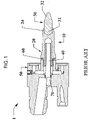
- Figs. 1 and 2 show one example of a known plasma gun 1 (only the certain main portions of the gun are shown for purposes of illustration) that has a replaceable cathode 10.
- the cathode 10 has a mounting portion 20 and a tip 30 from whose front end 32 a plasma arc discharges in a continuous manner during plasma spraying.
- the tip 30 typically has a rear portion 31 that is fixed to and extends into a receiving zone 24 of the mounting portion 20.
- the mounting portion 20 includes a main internal space 21 which is sized and configured to receive therein cooling fluid and accommodates therein a front portion of a cooling tube 40. Cooling fluid passes through the tube 40 via a main cooling passage 70 of the plasma gun 1.
- the mounting portion 20 also includes an external thread 22 which threads into comparable internal threads of the component 50 and functions to axially mechanically fix and electrically connect the cathode 10 to a main internal component 50 of the plasma gun 1.
- an external thread 22 which threads into comparable internal threads of the component 50 and functions to axially mechanically fix and electrically connect the cathode 10 to a main internal component 50 of the plasma gun 1.
- a seal or O-ring 60 is typically provided in an area of an annular connecting interface 23. Owing to its position in the interface 23, the O-ring 60 is subjected to relatively high temperatures. Additionally, its location in the interface 23 is not ideal from the standpoint of providing maximum electrical conductivity between the cathode 10 and the component 50. As such, providing a standardized interface which would offer significant improvement over known connecting interfaces between these components should take these considerations into account.
- WO2010/037380 A2 discloses an interchangeable electrode interface comprising a cathode for increasing the service life of the cathode, especially of the the emission insert provided in said cathode.
- the present invention provides a standard interface that takes into account one or more of the noted deficiencies and provides an interface that is better or improved from a mechanical location and orientation standpoint, provides for an improved electrical connection, and also improves sealing integrity and life. Such an arrangement can be used for a variety of plasma forming electrodes. The flexibility of the connecting interface is believed to offer a marked improvement over known designs.
- the interface arrangement in accordance with the invention can ideally serve as a common mechanical interface for mating an interchangeable cathode to a thermal spray plasma gun body.
- water flow may be carried between the gun body, through the cathode, and back out to a return water flow channel.
- the interface provides sufficient capability to passing an electrical current of up to about 800 amps at up to about 300 volts between gun body (or components thereof) and the cathode. The actual power through the interface will, of course, vary depending upon the specific materials to be sprayed with the gun and the desired coating characteristics.
- a first aspect of the invention provides an interchangeable electrode interface for a thermal spray plasma gun according to claim 1.
- the interchangeable electrode interface of the present invention comprises an interchangeable electrode which is a cathode electrode.
- the interchangeable electrode comprises a mounting portion, a first connecting section provided with an external thread, a first coupling surface and a tip having a front end for generation a continuous plasma arc discharge.
- the interchangeable electrode interface of the present invention further comprises a component arrangeable in the plasma gun, wherein said component comprises a second connecting section provided with an internal thread and a second annular coupling surface.
- the first and second annular coupling surfaces electrically and mechanically contact one another and, in a preferred embodiment, in an installed condition, form a main electrical interface without any non-metallic or non-electrically conductive seal interposed therein.
- the annular seal of the interchangeable electrode interface of the present invention is, in a preferred embodiment, an O-ring.
- the annular seal is arranged in an outer circumferential groove of an outer surface of the interchangeable electrode, or in an inner circumferential groove of an inner surface of the component.
- the seal is arranged to provide sealing between the inner surface of the component and the outer surface of the interchangeable electrode.
- the first aspect of the present invention is characterised in that the annular seal is located axially in front of the first and second annular coupling surfaces and the first and second annular coupling surfaces are located axially in front of the first and the second connecting section with reference to a center longitudinal axis of the interchangeable electrode extending in a direction from the first connecting section towards the front end.
- the interchangeable cathode electrode is a cathode electrode having an internal cooling space, and the seal is for preventing a cooling fluid from escaping the internal cooling space.
- first and second annular coupling surfaces are arranged generally perpendicular to a center longitudinal axis of the interchangeable electrode.
- the second aspect of the invention provides for a method of making a plasma spray gun according to claim 5.
- FIGS. 3 and 4 show one non-limiting example of a plasma gun 100 (only the certain main portions of the gun are shown for purposes of illustration) that has an interchangeable and replaceable cathode 110 in accordance with the invention.
- the cathode 110 is mechanically and electrically connected to a main portion 150 of the plasma gun 100 via an interface but which lacks any seal, i.e., the interface lacks any non-metallic or non-electrically conductive seal as will be described in detail below. Instead, a seal 160 is axially spaced from this interface.
- the cathode 110 has a mounting portion 120 and a tip 130 from whose front end 132 a plasma arc discharges in a continuous manner during plasma spraying.
- the tip 130 has a rear portion 131 that is fixed to and extends into a receiving zone 124 of the mounting portion 120.
- the mounting portion 120 includes a main internal space 121 which is sized and configured to receive therein cooling fluid and accommodates therein a front portion of a cooling tube 140. Cooling fluid passes through the tube 140 via a main cooling passage 170 of the plasma gun 100.
- the mounting portion 120 also includes an external thread 122 which threads into comparable internal threads 151 of the component 150 and functions to axially mechanically fix and electrically connect the cathode 110 to a main internal component 150 of the plasma gun 100.
- a seal or O-ring 160 at a location other than an area of an annular connecting interface formed between the interface coupling surface 123 of the cathode 110 and the interface coupling surface 152 of the internal component 150.
- the O-ring 160 is spaced from the interface 123/152 and is instead arranged in a generally circumferential groove 125.
- the groove 125 can be arranged on the cathode 110 as an outer circumferential groove as shown in FIGS. 3 and 4 or alternatively as an inner circumferential groove arranged on the internal component 150. Owing to its position spaced from the interface 123/152, the O-ring 160 is not subjected to relatively high temperatures as in the prior art. Additionally, its location spaced from the interface is more ideal from the standpoint of providing maximum electrical conductivity between the cathode 110 and the component 150. This is because surfaces of the interface which were previously spaced apart (see FIGS. 1 and 2 ) and which served to define a space for receiving therein an O-ring or seal can now be brought into electrical contact with one another. As a result of the configuration shown in FIGS. 3 and 4 , a standardized interface is provided which offers significant improvement over known connecting interfaces between the components 110 and 150.
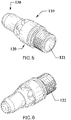
- an exemplary cathode 110 has a generally cylindrical mounting portion 120 and a generally cylindrical tip 130 from whose front end 132 a plasma arc discharges in a continuous manner during plasma spraying.
- the mounting portion 120 includes a generally cylindrical main internal space 121 which is sized and configured to receive therein cooling fluid and accommodates therein a front portion of a cooling tube 140 (see FIG. 4 ).
- the mounting portion 120 also includes an external thread 122 arranged on a rear end of the portion 120 as well as hex-shaped portion arranged adjacent the tip 130.
- the hex-shaped portion is sized and configured so that an operator can remove the cathode 110 using a suitable tool such as a wrench or socket wrench, and, in this way, unthread the external threads 122 from the internal threads 151 of the internal component 150 during cathode 110 removal.
- the same hex-shaped portion allows an operator to install the cathode 110 using a suitable tool such as a wrench or socket wrench, and, in this way, thread the external threads 122 into the internal threads of the internal component 150 during cathode 110 installation.
- a groove 125 can be arranged on the cathode 110 as an outer circumferential groove and this groove 125 is axially spaced from an interface coupling surface 123 of the cathode 110.
- the threaded connecting sections 122 and 151 can be of any type and are not limited to, for example, machine threads. Moreover, either the thread 122 or thread 151 need not be completely circumferential and can be in the form of intermittent threads. Non-limiting examples include 5/8 - 18 UNF thread.
- the interface 123/152 need not be limited to that shown in FIGS. 3 and 4 and can additionally also function as a stop for the threading on of the cathode 110.
- the O-ring 160 can be of any type, i.e., generally circular, square or rectangular in cross-section, and preferably functions to provide sealing for the cooling fluid circuit.
- the materials for certain components such as components 150, 120 and 130 can be the same as those used for comparable component utilized in conventional plasma guns such as that shown in FIGS. 1 and 2 .
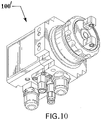
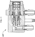
- FIGS. 9-11 show one non-limiting plasma gun 100' that can utilize the interchangeable interface shown in FIGS. 3 and 4 .
- a Sulzer Metco SinplexPro-90 Plasma Gun is provided with an interchangeable cathode (see FIG. 11 ) utilizing the interchangeable interface of the type exemplified in FIGS. 3 and 4 .
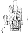
- FIGS. 12-14 show another non-limiting plasma gun 100" that can utilize the interchangeable interface shown in FIGS. 3 and 4 .
- a Sulzer Metco SinplexPro-180 Plasma Gun is provided with an interchangeable cathode (see FIG. 14 ) utilizing the interchangeable interface of the type exemplified in FIGS. 3 and 4 .
Description
- The present specification is based on and claims the benefit of
U.S. provisional application No. 61/645,272 filed on May 10, 2012 - The present invention relates generally to equipment for the thermal spraying of powdered materials. More specifically, the present invention relates to a cathode interface for use with a thermal spray plasma gun.
- A variety of thermal spray coatings have been used to protect various types of components. Coatings may provide various benefits such as to resist wear, retard corrosion, control clearances, salvage worn components, resist high temperatures and/or enhance electrical properties. These benefits can differ based on the coating material type and how those materials are applied. One group of spray coatings to which the subject matter of the present invention pertains in particular are those applied via the plasma spray process. This process has been used to apply many different types of coatings in numerous industries.
- Each material coating specification requires a specific range of velocity and temperature transferred to the powder particle to achieve the required material properties on the part. Improved consistency and efficiency in the delivery of thermal spray coatings remains an industry-wide goal.
- The plasma gun has been used as a process tool in the spray coatings industry due to the wide range of parameters that are achievable with this basic tool. A key element of any plasma gun is the cathode geometry. Variations in cathode geometry can allow a plasma gun to provide coating properties at a different temperatures and velocities from the same base equipment. During repeat use, cathode exhibit wear which leads to replacement of the part. Thus a single plasma gun typically required replacement of the cathode. Prior art configurations were such that replacement of the cathode was difficult and took a long time, leading to long down times when the part needed to be replaced.
- However, there are a number of factors that can prove challenging in replacing the a plasma gun cathode. Plasma spray guns must perform several different functions in order to achieve a successful coating process. Those functions include proper alignment of the cathode as well as cooling of the gun cathode during the spray process to prevent overheating. Accordingly proper flow of coolant sealing around the cathode area and adequate sealing of the cooling path is needed. An electrical connection between the cathode and the plasma gun is also required to serve as the return path for the plasma arc current flow. Precise orientation of mechanical location, electrical connections and water chamber seals must be achieved to obtain the desired gun operation and gun characteristics.
-
Figs. 1 and2 show one example of a known plasma gun 1 (only the certain main portions of the gun are shown for purposes of illustration) that has areplaceable cathode 10. As can be readily seen, thecathode 10 has amounting portion 20 and atip 30 from whose front end 32 a plasma arc discharges in a continuous manner during plasma spraying. Thetip 30 typically has arear portion 31 that is fixed to and extends into areceiving zone 24 of themounting portion 20. Themounting portion 20 includes a maininternal space 21 which is sized and configured to receive therein cooling fluid and accommodates therein a front portion of acooling tube 40. Cooling fluid passes through thetube 40 via amain cooling passage 70 of theplasma gun 1. Themounting portion 20 also includes anexternal thread 22 which threads into comparable internal threads of thecomponent 50 and functions to axially mechanically fix and electrically connect thecathode 10 to a maininternal component 50 of theplasma gun 1. However, to provide sealing between thecathode 10 and thecomponent 50 to among other things, prevent cooling fluid (typically pressurized) from escaping from thespace 21, a seal or O-ring 60 is typically provided in an area of anannular connecting interface 23. Owing to its position in theinterface 23, the O-ring 60 is subjected to relatively high temperatures. Additionally, its location in theinterface 23 is not ideal from the standpoint of providing maximum electrical conductivity between thecathode 10 and thecomponent 50. As such, providing a standardized interface which would offer significant improvement over known connecting interfaces between these components should take these considerations into account. - Utilizing a standard interface in a plasma gun has been utilized in areas such as the nozzle interface.
US 7,759,599 to HAWLEY et al. , for example, describes one such arrangement, the disclosure of which is hereby expressly incorporated by reference thereto in its entirety. However, providing a standard interface for a cathode of a plasma gun has unique challenges which are not addressed by this document. Moreover,US 6 320 156 B1 discloses replacement of consumable parts, such as the electrode, nozzle, or the like, in a plasma torch, in particular an electrode, insulating guide and a nozzle are fit together installed in a retainer cap. -
WO2010/037380 A2 discloses an interchangeable electrode interface comprising a cathode for increasing the service life of the cathode, especially of the the emission insert provided in said cathode. - A standard interface for each cathode that would assure proper orientation of all plasma gun components with each interchangeable cathode, while minimizing the risk of human error would be beneficial to the spray coating industry. Optimal orientation could extend the range of performance for a single thermal spray plasma gun. Thus, there remains a need in the art for a standard cathode interface for a thermal spray plasma gun that provides an optimal, efficient and repeatable cathode connection for a wide range of cathode geometries.
- The present invention provides a standard interface that takes into account one or more of the noted deficiencies and provides an interface that is better or improved from a mechanical location and orientation standpoint, provides for an improved electrical connection, and also improves sealing integrity and life. Such an arrangement can be used for a variety of plasma forming electrodes. The flexibility of the connecting interface is believed to offer a marked improvement over known designs.
- The interface arrangement in accordance with the invention can ideally serve as a common mechanical interface for mating an interchangeable cathode to a thermal spray plasma gun body. In the assembled configuration, water flow may be carried between the gun body, through the cathode, and back out to a return water flow channel. Also, the interface provides sufficient capability to passing an electrical current of up to about 800 amps at up to about 300 volts between gun body (or components thereof) and the cathode. The actual power through the interface will, of course, vary depending upon the specific materials to be sprayed with the gun and the desired coating characteristics.
- Accordingly, a first aspect of the invention provides an interchangeable electrode interface for a thermal spray plasma gun according to
claim 1. - Preferred embodiments of the first aspect of the invention are defined in the dependent claims.
- The interchangeable electrode interface of the present invention comprises an interchangeable electrode which is a cathode electrode.
- The interchangeable electrode comprises a mounting portion, a first connecting section provided with an external thread, a first coupling surface and a tip having a front end for generation a continuous plasma arc discharge.
- The interchangeable electrode interface of the present invention further comprises a component arrangeable in the plasma gun, wherein said component comprises a second connecting section provided with an internal thread and a second annular coupling surface.
- In the present invention, the first and second annular coupling surfaces electrically and mechanically contact one another and, in a preferred embodiment, in an installed condition, form a main electrical interface without any non-metallic or non-electrically conductive seal interposed therein.
- The annular seal of the interchangeable electrode interface of the present invention is, in a preferred embodiment, an O-ring.
- In the present invention, the annular seal is arranged in an outer circumferential groove of an outer surface of the interchangeable electrode, or in an inner circumferential groove of an inner surface of the component. The seal is arranged to provide sealing between the inner surface of the component and the outer surface of the interchangeable electrode.
- The first aspect of the present invention is characterised in that the annular seal is located axially in front of the first and second annular coupling surfaces and the first and second annular coupling surfaces are located axially in front of the first and the second connecting section with reference to a center longitudinal axis of the interchangeable electrode extending in a direction from the first connecting section towards the front end.
- The interchangeable cathode electrode is a cathode electrode having an internal cooling space, and the seal is for preventing a cooling fluid from escaping the internal cooling space.
- In a preferred embodiment, the first and second annular coupling surfaces are arranged generally perpendicular to a center longitudinal axis of the interchangeable electrode.
- The second aspect of the invention provides for a method of making a plasma spray gun according to claim 5.
- Further embodiments of the second aspect of the invention provides for a method of replacing an interchangeable electrode of a plasma spray gun comprising removing a used interchangeable electrode from the plasma spray gun and installing a new interchangeable electrode having the interchangeable interface in accordance with the the embodiments of the first aspect of the invention.
- Additional features of the invention will be set forth in the figures and any description which follows, and in part will be obvious from the description, or may be learned by practice of the invention. The features of the invention may be realized and obtained by way of the features, instrumentalities and/or feature combinations particularly pointed out hereafter without departing from the scope of the invention as defined in the appended claims.
- The present invention is further described in the detailed description which follows, in reference to the noted drawings by way of a non-limiting example embodiment of the present invention, and wherein:
-
FIG. 1 shows a cross-section view of an internal section of a prior art plasma gun; -
FIG. 2 shows an enlarged portion ofFIG. 1 ; -
FIG. 3 shows a cross-section view of an internal section of a plasma gun utilizing an interchangeable electrode interface in accordance with one non-limiting embodiment of the invention; -
FIG. 4 shows an enlarged portion ofFIG. 3 ; -
FIGS. 5 and 6 show front and back side perspective views of a cathode for use with the present invention; -
FIGS. 7 and 8 shows side and rear end view of the cathode shown inFIGS. 5 and 6 ; -
FIGS. 9 and10 show front and back side perspective views of an exemplary plasma gun utilizing an interchangeable electrode interface in accordance with one non-limiting embodiment of the invention; -
FIG. 11 shows a side cross-section view of the plasma gun shown inFIGS. 9 and10 ; -
FIGS. 12 and13 show front and back side perspective views of another exemplary plasma gun utilizing an interchangeable electrode interface in accordance with one non-limiting embodiment of the invention; and -
FIG. 14 shows a side cross-section view of the plasma gun shown inFIGS. 12 and13 . - The particulars shown herein are by way of example and for purposes of illustrative discussion of the embodiments of the present invention only and are presented in the cause of providing what is believed to be the most useful and readily understood description of the principles and conceptual aspects of the present invention. In this regard, no attempt is made to show structural details of the present invention in more detail than is necessary for the fundamental understanding of the present invention, the description taken with the drawings making apparent to those skilled in the art how the several forms of the present invention may be embodied in practice.
-
FIGS. 3 and4 show one non-limiting example of a plasma gun 100 (only the certain main portions of the gun are shown for purposes of illustration) that has an interchangeable andreplaceable cathode 110 in accordance with the invention. As can be readily seen when compared to the knownarrangement 10/50 shown inFIGS. 1 and2 , thecathode 110 is mechanically and electrically connected to amain portion 150 of theplasma gun 100 via an interface but which lacks any seal, i.e., the interface lacks any non-metallic or non-electrically conductive seal as will be described in detail below. Instead, aseal 160 is axially spaced from this interface. - Thus, in the embodiment of
FIGS. 3 and4 , thecathode 110 has a mountingportion 120 and atip 130 from whose front end 132 a plasma arc discharges in a continuous manner during plasma spraying. Thetip 130 has arear portion 131 that is fixed to and extends into a receivingzone 124 of the mountingportion 120. The mountingportion 120 includes a maininternal space 121 which is sized and configured to receive therein cooling fluid and accommodates therein a front portion of acooling tube 140. Cooling fluid passes through thetube 140 via amain cooling passage 170 of theplasma gun 100. The mountingportion 120 also includes anexternal thread 122 which threads into comparableinternal threads 151 of thecomponent 150 and functions to axially mechanically fix and electrically connect thecathode 110 to a maininternal component 150 of theplasma gun 100. However, to provide sealing between thecathode 110 and thecomponent 150 to among other things, prevent cooling fluid (typically pressurized) from escaping from thespace 121, a seal or O-ring 160 at a location other than an area of an annular connecting interface formed between theinterface coupling surface 123 of thecathode 110 and theinterface coupling surface 152 of theinternal component 150. In the embodiment ofFIGS. 3 and4 , the O-ring 160 is spaced from theinterface 123/152 and is instead arranged in a generallycircumferential groove 125. Thegroove 125 can be arranged on thecathode 110 as an outer circumferential groove as shown inFIGS. 3 and4 or alternatively as an inner circumferential groove arranged on theinternal component 150. Owing to its position spaced from theinterface 123/152, the O-ring 160 is not subjected to relatively high temperatures as in the prior art. Additionally, its location spaced from the interface is more ideal from the standpoint of providing maximum electrical conductivity between thecathode 110 and thecomponent 150. This is because surfaces of the interface which were previously spaced apart (seeFIGS. 1 and2 ) and which served to define a space for receiving therein an O-ring or seal can now be brought into electrical contact with one another. As a result of the configuration shown inFIGS. 3 and4 , a standardized interface is provided which offers significant improvement over known connecting interfaces between thecomponents - Referring now to
FIGS. 5-8 , it can be seen that anexemplary cathode 110 has a generally cylindrical mountingportion 120 and a generallycylindrical tip 130 from whose front end 132 a plasma arc discharges in a continuous manner during plasma spraying. The mountingportion 120 includes a generally cylindrical maininternal space 121 which is sized and configured to receive therein cooling fluid and accommodates therein a front portion of a cooling tube 140 (seeFIG. 4 ). The mountingportion 120 also includes anexternal thread 122 arranged on a rear end of theportion 120 as well as hex-shaped portion arranged adjacent thetip 130. The hex-shaped portion is sized and configured so that an operator can remove thecathode 110 using a suitable tool such as a wrench or socket wrench, and, in this way, unthread theexternal threads 122 from theinternal threads 151 of theinternal component 150 duringcathode 110 removal. The same hex-shaped portion allows an operator to install thecathode 110 using a suitable tool such as a wrench or socket wrench, and, in this way, thread theexternal threads 122 into the internal threads of theinternal component 150 duringcathode 110 installation. As can be seen inFIG. 7 , agroove 125 can be arranged on thecathode 110 as an outer circumferential groove and thisgroove 125 is axially spaced from aninterface coupling surface 123 of thecathode 110. - In embodiments, the threaded connecting
sections thread 122 orthread 151 need not be completely circumferential and can be in the form of intermittent threads. Non-limiting examples include 5/8 - 18 UNF thread. Theinterface 123/152 need not be limited to that shown inFIGS. 3 and4 and can additionally also function as a stop for the threading on of thecathode 110. In embodiments, the O-ring 160 can be of any type, i.e., generally circular, square or rectangular in cross-section, and preferably functions to provide sealing for the cooling fluid circuit. The materials for certain components such ascomponents FIGS. 1 and2 . -
FIGS. 9-11 show onenon-limiting plasma gun 100' that can utilize the interchangeable interface shown inFIGS. 3 and4 . Here, a Sulzer Metco SinplexPro-90 Plasma Gun is provided with an interchangeable cathode (seeFIG. 11 ) utilizing the interchangeable interface of the type exemplified inFIGS. 3 and4 . -
FIGS. 12-14 show anothernon-limiting plasma gun 100" that can utilize the interchangeable interface shown inFIGS. 3 and4 . Here, a Sulzer Metco SinplexPro-180 Plasma Gun is provided with an interchangeable cathode (seeFIG. 14 ) utilizing the interchangeable interface of the type exemplified inFIGS. 3 and4 . - It is noted that the foregoing examples have been provided merely for the purpose of explanation and are in no way to be construed as limiting of the present invention, which is limited as defined by the appended claims.
Claims (5)
- An interchangeable electrode interface for a thermal spray plasma gun (100), comprising:an interchangeable electrode (110) comprising a mounting portion (120) having an internal space (121) sized and configured for receiving a cooling fluid therein and for accommodating therein a front portion of a cooling tube (140), a receiving zone (124),a first connecting section (122), and a first annular coupling surface (123), wherein the interchangeable electrode (110) is a cathode (110) further comprising a tip (130) having a front end (132) for generating a continuous plasma arc discharge and having a rear portion (131) fixed to and extending into the receiving zone (124);a component (150) arrangeable in the plasma gun (100), the component comprising a second connecting section (151) and a second annular coupling surface (152); andan annular seal (160) for preventing the cooling fluid from escaping the internal space (121) and being spaced from the first and second annular coupling surfaces,wherein the first connecting section (122) comprises an external thread (122) and the second connecting section (151) comprises an internal thread (151),wherein the first (123) and second (152) annular coupling surfaces are in electrical and mechanical contact with one another, and the first connecting section (122) is removably connectable to the second connecting section (151),wherein the annular seal (160) is arranged to provide sealing between an inner circumferential surface of the component (150) and an outer circumferential surface of the cathode (110); andthe annular seal (160) is arranged in an outer circumferential groove (125) on the outer circumferential surface; or the annular seal (160) is arranged in an inner circumferential groove on the inner circumferential surface;characterized in that the annular seal (160) is located axially in front of the first (123) and second (152) annular coupling surfaces and the first (123) and second (152) annular coupling surfaces are located axially in front of the first (122) and the second connecting section (151) with reference to a center longitudinal axis of the interchangeable electrode (110) extending in a direction from the first connecting section (122) towards the front end (132).
- The electrode interface of claim 1, wherein, in an installed condition, the first and second annular coupling surfaces form a main electrical interface without any non-metallic or non-electrically conductive seal interposed therein.
- The electrode interface of claim 1, wherein the annular seal is an O-ring (160).
- The electrode interface of claim 1, wherein the first (123) and second (152) annular coupling surfaces being arranged generally perpendicular to a center longitudinal axis of the interchangeable electrode (120).
- A method of making a thermal spray plasma gun (100) comprising:
installing, in the plasma gun (100), the interchangeable interface in accordance with anyone of claims 1-4.
Applications Claiming Priority (2)
| Application Number | Priority Date | Filing Date | Title |
|---|---|---|---|
| US201261645272P | 2012-05-10 | 2012-05-10 | |
| PCT/US2013/039847 WO2013169710A1 (en) | 2012-05-10 | 2013-05-07 | Cathode interface for a plasma gun and method of making and using the same |
Publications (3)
| Publication Number | Publication Date |
|---|---|
| EP2848098A1 EP2848098A1 (en) | 2015-03-18 |
| EP2848098A4 EP2848098A4 (en) | 2015-12-09 |
| EP2848098B1 true EP2848098B1 (en) | 2022-07-06 |
Family
ID=49551203
Family Applications (1)
| Application Number | Title | Priority Date | Filing Date |
|---|---|---|---|
| EP13787759.3A Active EP2848098B1 (en) | 2012-05-10 | 2013-05-07 | Exchangeable cathode interface for a plasma spray gun and method of making a plasma spray gun with the same |
Country Status (6)
| Country | Link |
|---|---|
| US (1) | US9142390B2 (en) |
| EP (1) | EP2848098B1 (en) |
| JP (1) | JP6205409B2 (en) |
| AU (1) | AU2013259743B2 (en) |
| CA (1) | CA2867600C (en) |
| WO (1) | WO2013169710A1 (en) |
Families Citing this family (4)
| Publication number | Priority date | Publication date | Assignee | Title |
|---|---|---|---|---|
| RU2594413C2 (en) | 2012-01-27 | 2016-08-20 | ЗУЛЬЦЕР МЕТКО (ЮЭс), ИНК. | Gun for thermal spraying with removable nozzle tip and method for its production and use |
| US9398679B2 (en) * | 2014-05-19 | 2016-07-19 | Lincoln Global, Inc. | Air cooled plasma torch and components thereof |
| CN115066984A (en) * | 2020-03-06 | 2022-09-16 | 普莱克斯S.T.技术有限公司 | Modified cathode assembly and holder assembly for plasma arc torch |
| FR3132408A1 (en) * | 2022-01-31 | 2023-08-04 | Akryvia | PLASMA CUTTING TORCH WITH INDIRECT CONSUMABLE COOLING |
Citations (4)
| Publication number | Priority date | Publication date | Assignee | Title |
|---|---|---|---|---|
| US4780591A (en) * | 1986-06-13 | 1988-10-25 | The Perkin-Elmer Corporation | Plasma gun with adjustable cathode |
| US6232574B1 (en) * | 2000-01-13 | 2001-05-15 | The Esab Group, Inc. | Method and apparatus for improving plasma ARC consumable life |
| US20040262270A1 (en) * | 2003-06-26 | 2004-12-30 | Hardwick Steven F. | Apparatus for proper alignment of components in a plasma arc torch |
| WO2010037380A2 (en) * | 2008-12-18 | 2010-04-08 | Kjellberg Finsterwalde Plasma Und Maschinen Gmbh | Electrode for a plasma burner |
Family Cites Families (10)
| Publication number | Priority date | Publication date | Assignee | Title |
|---|---|---|---|---|
| JPS60186047U (en) * | 1984-05-21 | 1985-12-10 | 昭和電工株式会社 | plasma spray gun |
| US4688722A (en) * | 1984-09-04 | 1987-08-25 | The Perkin-Elmer Corporation | Nozzle assembly for plasma spray gun |
| US5298835A (en) | 1988-07-21 | 1994-03-29 | Electro-Plasma, Inc. | Modular segmented cathode plasma generator |
| CA2002497A1 (en) * | 1988-12-28 | 1990-06-28 | Anthony J. Rotolico | High velocity powder thermal spray method for spraying non-meltable materials |
| JP3010879B2 (en) * | 1992-02-25 | 2000-02-21 | 松下電器産業株式会社 | Plasma torch |
| JPH07282994A (en) * | 1994-04-05 | 1995-10-27 | Nippon Steel Corp | Plasma torch sealing structure |
| JP3554221B2 (en) * | 1999-05-10 | 2004-08-18 | 株式会社小松製作所 | Plasma torch and electrodes of plasma torch |
| US6320156B1 (en) * | 1999-05-10 | 2001-11-20 | Komatsu Ltd. | Plasma processing device, plasma torch and method for replacing components of same |
| US6559407B2 (en) * | 2001-04-05 | 2003-05-06 | Ford Global Technologies, Inc. | Cathode assembly for an electric arc spray apparatus |
| US7759599B2 (en) | 2005-04-29 | 2010-07-20 | Sulzer Metco (Us), Inc. | Interchangeable plasma nozzle interface |
-
2013
- 2013-05-07 JP JP2015511597A patent/JP6205409B2/en active Active
- 2013-05-07 CA CA2867600A patent/CA2867600C/en active Active
- 2013-05-07 EP EP13787759.3A patent/EP2848098B1/en active Active
- 2013-05-07 US US14/128,265 patent/US9142390B2/en active Active
- 2013-05-07 WO PCT/US2013/039847 patent/WO2013169710A1/en active Application Filing
- 2013-05-07 AU AU2013259743A patent/AU2013259743B2/en not_active Ceased
Patent Citations (4)
| Publication number | Priority date | Publication date | Assignee | Title |
|---|---|---|---|---|
| US4780591A (en) * | 1986-06-13 | 1988-10-25 | The Perkin-Elmer Corporation | Plasma gun with adjustable cathode |
| US6232574B1 (en) * | 2000-01-13 | 2001-05-15 | The Esab Group, Inc. | Method and apparatus for improving plasma ARC consumable life |
| US20040262270A1 (en) * | 2003-06-26 | 2004-12-30 | Hardwick Steven F. | Apparatus for proper alignment of components in a plasma arc torch |
| WO2010037380A2 (en) * | 2008-12-18 | 2010-04-08 | Kjellberg Finsterwalde Plasma Und Maschinen Gmbh | Electrode for a plasma burner |
Also Published As
| Publication number | Publication date |
|---|---|
| CA2867600A1 (en) | 2013-11-14 |
| AU2013259743B2 (en) | 2015-07-16 |
| CA2867600C (en) | 2020-06-30 |
| JP6205409B2 (en) | 2017-09-27 |
| US9142390B2 (en) | 2015-09-22 |
| US20140167597A1 (en) | 2014-06-19 |
| JP2015524021A (en) | 2015-08-20 |
| WO2013169710A1 (en) | 2013-11-14 |
| EP2848098A1 (en) | 2015-03-18 |
| AU2013259743A1 (en) | 2014-11-13 |
| EP2848098A4 (en) | 2015-12-09 |
Similar Documents
| Publication | Publication Date | Title |
|---|---|---|
| EP1875785B1 (en) | Interchangeable plasma nozzle interface | |
| US6989505B2 (en) | Plasma arc torch consumables cartridge | |
| CA2826791C (en) | Plasma cutting tip with advanced cooling passageways | |
| EP2848098B1 (en) | Exchangeable cathode interface for a plasma spray gun and method of making a plasma spray gun with the same | |
| US7071443B2 (en) | Plasma arc torch | |
| US7126080B1 (en) | Plasma gas distributor with integral metering and flow passageways | |
| US6559407B2 (en) | Cathode assembly for an electric arc spray apparatus | |
| US10917961B2 (en) | High temperature isolating insert for plasma cutting torch | |
| CN113475165A (en) | Electrode for plasma gun |
Legal Events
| Date | Code | Title | Description |
|---|---|---|---|
| PUAI | Public reference made under article 153(3) epc to a published international application that has entered the european phase |
Free format text: ORIGINAL CODE: 0009012 |
|
| 17P | Request for examination filed |
Effective date: 20141210 |
|
| AK | Designated contracting states |
Kind code of ref document: A1 Designated state(s): AL AT BE BG CH CY CZ DE DK EE ES FI FR GB GR HR HU IE IS IT LI LT LU LV MC MK MT NL NO PL PT RO RS SE SI SK SM TR |
|
| AX | Request for extension of the european patent |
Extension state: BA ME |
|
| DAX | Request for extension of the european patent (deleted) | ||
| RIN1 | Information on inventor provided before grant (corrected) |
Inventor name: SAVILL, ROBERT F. Inventor name: HAWLEY, DAVE Inventor name: MOLZ, RONALD J. |
|
| RA4 | Supplementary search report drawn up and despatched (corrected) |
Effective date: 20151111 |
|
| RIC1 | Information provided on ipc code assigned before grant |
Ipc: H01J 9/18 20060101ALI20151105BHEP Ipc: H05H 1/42 20060101ALI20151105BHEP Ipc: H01J 37/32 20060101ALI20151105BHEP Ipc: H05H 1/34 20060101AFI20151105BHEP |
|
| STAA | Information on the status of an ep patent application or granted ep patent |
Free format text: STATUS: EXAMINATION IS IN PROGRESS |
|
| 17Q | First examination report despatched |
Effective date: 20191023 |
|
| RAP1 | Party data changed (applicant data changed or rights of an application transferred) |
Owner name: OERLIKON METCO (US) INC. |
|
| STAA | Information on the status of an ep patent application or granted ep patent |
Free format text: STATUS: EXAMINATION IS IN PROGRESS |
|
| STAA | Information on the status of an ep patent application or granted ep patent |
Free format text: STATUS: EXAMINATION IS IN PROGRESS |
|
| RIC1 | Information provided on ipc code assigned before grant |
Ipc: H05H 1/34 20060101AFI20211117BHEP |
|
| GRAP | Despatch of communication of intention to grant a patent |
Free format text: ORIGINAL CODE: EPIDOSNIGR1 |
|
| STAA | Information on the status of an ep patent application or granted ep patent |
Free format text: STATUS: GRANT OF PATENT IS INTENDED |
|
| INTG | Intention to grant announced |
Effective date: 20220110 |
|
| GRAS | Grant fee paid |
Free format text: ORIGINAL CODE: EPIDOSNIGR3 |
|
| GRAA | (expected) grant |
Free format text: ORIGINAL CODE: 0009210 |
|
| STAA | Information on the status of an ep patent application or granted ep patent |
Free format text: STATUS: THE PATENT HAS BEEN GRANTED |
|
| AK | Designated contracting states |
Kind code of ref document: B1 Designated state(s): AL AT BE BG CH CY CZ DE DK EE ES FI FR GB GR HR HU IE IS IT LI LT LU LV MC MK MT NL NO PL PT RO RS SE SI SK SM TR |
|
| REG | Reference to a national code |
Ref country code: GB Ref legal event code: FG4D |
|
| REG | Reference to a national code |
Ref country code: AT Ref legal event code: REF Ref document number: 1503800 Country of ref document: AT Kind code of ref document: T Effective date: 20220715 Ref country code: CH Ref legal event code: EP |
|
| REG | Reference to a national code |
Ref country code: DE Ref legal event code: R096 Ref document number: 602013082013 Country of ref document: DE |
|
| REG | Reference to a national code |
Ref country code: IE Ref legal event code: FG4D |
|
| REG | Reference to a national code |
Ref country code: NL Ref legal event code: FP |
|
| REG | Reference to a national code |
Ref country code: LT Ref legal event code: MG9D |
|
| PG25 | Lapsed in a contracting state [announced via postgrant information from national office to epo] |
Ref country code: SE Free format text: LAPSE BECAUSE OF FAILURE TO SUBMIT A TRANSLATION OF THE DESCRIPTION OR TO PAY THE FEE WITHIN THE PRESCRIBED TIME-LIMIT Effective date: 20220706 Ref country code: RS Free format text: LAPSE BECAUSE OF FAILURE TO SUBMIT A TRANSLATION OF THE DESCRIPTION OR TO PAY THE FEE WITHIN THE PRESCRIBED TIME-LIMIT Effective date: 20220706 Ref country code: PT Free format text: LAPSE BECAUSE OF FAILURE TO SUBMIT A TRANSLATION OF THE DESCRIPTION OR TO PAY THE FEE WITHIN THE PRESCRIBED TIME-LIMIT Effective date: 20221107 Ref country code: NO Free format text: LAPSE BECAUSE OF FAILURE TO SUBMIT A TRANSLATION OF THE DESCRIPTION OR TO PAY THE FEE WITHIN THE PRESCRIBED TIME-LIMIT Effective date: 20221006 Ref country code: LV Free format text: LAPSE BECAUSE OF FAILURE TO SUBMIT A TRANSLATION OF THE DESCRIPTION OR TO PAY THE FEE WITHIN THE PRESCRIBED TIME-LIMIT Effective date: 20220706 Ref country code: LT Free format text: LAPSE BECAUSE OF FAILURE TO SUBMIT A TRANSLATION OF THE DESCRIPTION OR TO PAY THE FEE WITHIN THE PRESCRIBED TIME-LIMIT Effective date: 20220706 Ref country code: FI Free format text: LAPSE BECAUSE OF FAILURE TO SUBMIT A TRANSLATION OF THE DESCRIPTION OR TO PAY THE FEE WITHIN THE PRESCRIBED TIME-LIMIT Effective date: 20220706 Ref country code: ES Free format text: LAPSE BECAUSE OF FAILURE TO SUBMIT A TRANSLATION OF THE DESCRIPTION OR TO PAY THE FEE WITHIN THE PRESCRIBED TIME-LIMIT Effective date: 20220706 |
|
| REG | Reference to a national code |
Ref country code: AT Ref legal event code: MK05 Ref document number: 1503800 Country of ref document: AT Kind code of ref document: T Effective date: 20220706 |
|
| PG25 | Lapsed in a contracting state [announced via postgrant information from national office to epo] |
Ref country code: PL Free format text: LAPSE BECAUSE OF FAILURE TO SUBMIT A TRANSLATION OF THE DESCRIPTION OR TO PAY THE FEE WITHIN THE PRESCRIBED TIME-LIMIT Effective date: 20220706 Ref country code: IS Free format text: LAPSE BECAUSE OF FAILURE TO SUBMIT A TRANSLATION OF THE DESCRIPTION OR TO PAY THE FEE WITHIN THE PRESCRIBED TIME-LIMIT Effective date: 20221106 Ref country code: HR Free format text: LAPSE BECAUSE OF FAILURE TO SUBMIT A TRANSLATION OF THE DESCRIPTION OR TO PAY THE FEE WITHIN THE PRESCRIBED TIME-LIMIT Effective date: 20220706 Ref country code: GR Free format text: LAPSE BECAUSE OF FAILURE TO SUBMIT A TRANSLATION OF THE DESCRIPTION OR TO PAY THE FEE WITHIN THE PRESCRIBED TIME-LIMIT Effective date: 20221007 |
|
| REG | Reference to a national code |
Ref country code: DE Ref legal event code: R097 Ref document number: 602013082013 Country of ref document: DE |
|
| PG25 | Lapsed in a contracting state [announced via postgrant information from national office to epo] |
Ref country code: SM Free format text: LAPSE BECAUSE OF FAILURE TO SUBMIT A TRANSLATION OF THE DESCRIPTION OR TO PAY THE FEE WITHIN THE PRESCRIBED TIME-LIMIT Effective date: 20220706 Ref country code: RO Free format text: LAPSE BECAUSE OF FAILURE TO SUBMIT A TRANSLATION OF THE DESCRIPTION OR TO PAY THE FEE WITHIN THE PRESCRIBED TIME-LIMIT Effective date: 20220706 Ref country code: DK Free format text: LAPSE BECAUSE OF FAILURE TO SUBMIT A TRANSLATION OF THE DESCRIPTION OR TO PAY THE FEE WITHIN THE PRESCRIBED TIME-LIMIT Effective date: 20220706 Ref country code: CZ Free format text: LAPSE BECAUSE OF FAILURE TO SUBMIT A TRANSLATION OF THE DESCRIPTION OR TO PAY THE FEE WITHIN THE PRESCRIBED TIME-LIMIT Effective date: 20220706 Ref country code: AT Free format text: LAPSE BECAUSE OF FAILURE TO SUBMIT A TRANSLATION OF THE DESCRIPTION OR TO PAY THE FEE WITHIN THE PRESCRIBED TIME-LIMIT Effective date: 20220706 |
|
| PLBE | No opposition filed within time limit |
Free format text: ORIGINAL CODE: 0009261 |
|
| STAA | Information on the status of an ep patent application or granted ep patent |
Free format text: STATUS: NO OPPOSITION FILED WITHIN TIME LIMIT |
|
| PG25 | Lapsed in a contracting state [announced via postgrant information from national office to epo] |
Ref country code: SK Free format text: LAPSE BECAUSE OF FAILURE TO SUBMIT A TRANSLATION OF THE DESCRIPTION OR TO PAY THE FEE WITHIN THE PRESCRIBED TIME-LIMIT Effective date: 20220706 Ref country code: EE Free format text: LAPSE BECAUSE OF FAILURE TO SUBMIT A TRANSLATION OF THE DESCRIPTION OR TO PAY THE FEE WITHIN THE PRESCRIBED TIME-LIMIT Effective date: 20220706 |
|
| 26N | No opposition filed |
Effective date: 20230411 |
|
| PG25 | Lapsed in a contracting state [announced via postgrant information from national office to epo] |
Ref country code: AL Free format text: LAPSE BECAUSE OF FAILURE TO SUBMIT A TRANSLATION OF THE DESCRIPTION OR TO PAY THE FEE WITHIN THE PRESCRIBED TIME-LIMIT Effective date: 20220706 |
|
| PGFP | Annual fee paid to national office [announced via postgrant information from national office to epo] |
Ref country code: NL Payment date: 20230525 Year of fee payment: 11 Ref country code: IT Payment date: 20230525 Year of fee payment: 11 Ref country code: FR Payment date: 20230523 Year of fee payment: 11 Ref country code: DE Payment date: 20230530 Year of fee payment: 11 Ref country code: CH Payment date: 20230602 Year of fee payment: 11 |
|
| PG25 | Lapsed in a contracting state [announced via postgrant information from national office to epo] |
Ref country code: SI Free format text: LAPSE BECAUSE OF FAILURE TO SUBMIT A TRANSLATION OF THE DESCRIPTION OR TO PAY THE FEE WITHIN THE PRESCRIBED TIME-LIMIT Effective date: 20220706 |
|
| PGFP | Annual fee paid to national office [announced via postgrant information from national office to epo] |
Ref country code: GB Payment date: 20230523 Year of fee payment: 11 |
|
| PG25 | Lapsed in a contracting state [announced via postgrant information from national office to epo] |
Ref country code: MC Free format text: LAPSE BECAUSE OF FAILURE TO SUBMIT A TRANSLATION OF THE DESCRIPTION OR TO PAY THE FEE WITHIN THE PRESCRIBED TIME-LIMIT Effective date: 20220706 |
|
| REG | Reference to a national code |
Ref country code: BE Ref legal event code: MM Effective date: 20230531 |
|
| PG25 | Lapsed in a contracting state [announced via postgrant information from national office to epo] |
Ref country code: MC Free format text: LAPSE BECAUSE OF FAILURE TO SUBMIT A TRANSLATION OF THE DESCRIPTION OR TO PAY THE FEE WITHIN THE PRESCRIBED TIME-LIMIT Effective date: 20220706 Ref country code: LU Free format text: LAPSE BECAUSE OF NON-PAYMENT OF DUE FEES Effective date: 20230507 |
|
| REG | Reference to a national code |
Ref country code: IE Ref legal event code: MM4A |