EP2847882B1 - Rank-specific feedback for improved mimo support - Google Patents
Rank-specific feedback for improved mimo support Download PDFInfo
- Publication number
- EP2847882B1 EP2847882B1 EP13722660.1A EP13722660A EP2847882B1 EP 2847882 B1 EP2847882 B1 EP 2847882B1 EP 13722660 A EP13722660 A EP 13722660A EP 2847882 B1 EP2847882 B1 EP 2847882B1
- Authority
- EP
- European Patent Office
- Prior art keywords
- csi
- pmi
- rank value
- admissible
- feedback
- Prior art date
- Legal status (The legal status is an assumption and is not a legal conclusion. Google has not performed a legal analysis and makes no representation as to the accuracy of the status listed.)
- Active
Links
Images


Classifications
-
- H—ELECTRICITY
- H04—ELECTRIC COMMUNICATION TECHNIQUE
- H04W—WIRELESS COMMUNICATION NETWORKS
- H04W72/00—Local resource management
- H04W72/20—Control channels or signalling for resource management
- H04W72/21—Control channels or signalling for resource management in the uplink direction of a wireless link, i.e. towards the network
-
- H—ELECTRICITY
- H04—ELECTRIC COMMUNICATION TECHNIQUE
- H04B—TRANSMISSION
- H04B17/00—Monitoring; Testing
- H04B17/20—Monitoring; Testing of receivers
- H04B17/24—Monitoring; Testing of receivers with feedback of measurements to the transmitter
-
- H—ELECTRICITY
- H04—ELECTRIC COMMUNICATION TECHNIQUE
- H04B—TRANSMISSION
- H04B7/00—Radio transmission systems, i.e. using radiation field
- H04B7/02—Diversity systems; Multi-antenna system, i.e. transmission or reception using multiple antennas
- H04B7/04—Diversity systems; Multi-antenna system, i.e. transmission or reception using multiple antennas using two or more spaced independent antennas
- H04B7/0413—MIMO systems
- H04B7/0417—Feedback systems
-
- H—ELECTRICITY
- H04—ELECTRIC COMMUNICATION TECHNIQUE
- H04B—TRANSMISSION
- H04B7/00—Radio transmission systems, i.e. using radiation field
- H04B7/02—Diversity systems; Multi-antenna system, i.e. transmission or reception using multiple antennas
- H04B7/04—Diversity systems; Multi-antenna system, i.e. transmission or reception using multiple antennas using two or more spaced independent antennas
- H04B7/0413—MIMO systems
- H04B7/0456—Selection of precoding matrices or codebooks, e.g. using matrices antenna weighting
-
- H—ELECTRICITY
- H04—ELECTRIC COMMUNICATION TECHNIQUE
- H04B—TRANSMISSION
- H04B7/00—Radio transmission systems, i.e. using radiation field
- H04B7/02—Diversity systems; Multi-antenna system, i.e. transmission or reception using multiple antennas
- H04B7/04—Diversity systems; Multi-antenna system, i.e. transmission or reception using multiple antennas using two or more spaced independent antennas
- H04B7/06—Diversity systems; Multi-antenna system, i.e. transmission or reception using multiple antennas using two or more spaced independent antennas at the transmitting station
- H04B7/0613—Diversity systems; Multi-antenna system, i.e. transmission or reception using multiple antennas using two or more spaced independent antennas at the transmitting station using simultaneous transmission
- H04B7/0615—Diversity systems; Multi-antenna system, i.e. transmission or reception using multiple antennas using two or more spaced independent antennas at the transmitting station using simultaneous transmission of weighted versions of same signal
- H04B7/0619—Diversity systems; Multi-antenna system, i.e. transmission or reception using multiple antennas using two or more spaced independent antennas at the transmitting station using simultaneous transmission of weighted versions of same signal using feedback from receiving side
- H04B7/0621—Feedback content
- H04B7/0632—Channel quality parameters, e.g. channel quality indicator [CQI]
-
- H—ELECTRICITY
- H04—ELECTRIC COMMUNICATION TECHNIQUE
- H04B—TRANSMISSION
- H04B7/00—Radio transmission systems, i.e. using radiation field
- H04B7/02—Diversity systems; Multi-antenna system, i.e. transmission or reception using multiple antennas
- H04B7/04—Diversity systems; Multi-antenna system, i.e. transmission or reception using multiple antennas using two or more spaced independent antennas
- H04B7/06—Diversity systems; Multi-antenna system, i.e. transmission or reception using multiple antennas using two or more spaced independent antennas at the transmitting station
- H04B7/0613—Diversity systems; Multi-antenna system, i.e. transmission or reception using multiple antennas using two or more spaced independent antennas at the transmitting station using simultaneous transmission
- H04B7/0615—Diversity systems; Multi-antenna system, i.e. transmission or reception using multiple antennas using two or more spaced independent antennas at the transmitting station using simultaneous transmission of weighted versions of same signal
- H04B7/0619—Diversity systems; Multi-antenna system, i.e. transmission or reception using multiple antennas using two or more spaced independent antennas at the transmitting station using simultaneous transmission of weighted versions of same signal using feedback from receiving side
- H04B7/0636—Feedback format
- H04B7/0639—Using selective indices, e.g. of a codebook, e.g. pre-distortion matrix index [PMI] or for beam selection
Definitions
- the present disclosure relates generally to communication systems, and more particularly, to a wireless communications networks that support terminals with multiple antennae.
- Wireless communication systems are widely deployed to provide various telecommunication services such as telephony, video, data, messaging, and broadcasts.
- Typical wireless communication systems may employ multiple-access technologies capable of supporting communication with multiple users by sharing available system resources (e.g., bandwidth, transmit power).
- multiple-access technologies include code division multiple access (CDMA) systems, time division multiple access (TDMA) systems, frequency division multiple access (FDMA) systems, orthogonal frequency division multiple access (OFDMA) systems, single-carrier frequency division multiple access (SC-FDMA) systems, and time division synchronous code division multiple access (TD-SCDMA) systems.
- CDMA code division multiple access
- TDMA time division multiple access
- FDMA frequency division multiple access
- OFDMA orthogonal frequency division multiple access
- SC-FDMA single-carrier frequency division multiple access
- TD-SCDMA time division synchronous code division multiple access
- LTE Long Term Evolution
- UMTS Universal Mobile Telecommunications System
- 3GPP Third Generation Partnership Project
- DL downlink
- UL uplink
- MIMO multiple-input multiple-output
- Document US 2011/032839 A1 discloses that single user and multiuser MIMO transmission in a cellular network may be performed by a base station (eNB) transmitting either one, two, or more transmission layers.
- a user equipment (UE) receives a reference symbol from the base station.
- the UE processes the reference symbol with one or more of a plurality of precoding matrices to form a plurality of channel quality indices (CQI).
- CQI channel quality indices
- the UE provides feedback to the eNB comprising one or more feedback CQI selected from the plurality of CQI and one or more precoding matrix indicators (PMI) identifying the one or more precoding matrices used to form each of the one or more feedback CQIs for two or more ranks.
- PMI precoding matrix indicators
- the present invention provides a solution according to the subject-matter of the independent claims.
- a UE operates in single user MIMO (SU-MIMO) mode or multi-user MIMO (MU-MIMO) mode and the UE may dynamically switch between SU-MIMO and MU-MIMO based on a determination of base station scheduling.
- SU-MIMO single user MIMO
- MU-MIMO multi-user MIMO
- the UE only provides a single precoding matrix indicator (PMI) which is not optimal or balanced for all possible ranks.
- PMI precoding matrix indicator
- Various aspects of the disclosure relate to providing multiple PMIs for a plurality of ranks or a single PMI that is balanced among different ranks. The provision of multiple PMIs or a balanced PMI by the terminal enables improved performance over multiple ranks as compared to when the UE provides only a single PMI based on a single rank.
- a UE can be configured to use a precoding matrix indicator (PMI) for the UE channel state information feedback.
- the PMI may comprise a signal fed back by the UE and related to MIMO operation.
- the PMI may correspond to the index of a precoder within a codebook shared by the UE and a base station.
- PMI may be associated with a rank indicator (RI) that is signaled to the base station by the UE and which corresponds to the number of useful transmission layers for spatial multiplexing.
- RI rank indicator
- the type of PMI supported may depend on the type of channel state information feedback.
- the UE may report a PMI that targets a balanced performance among different ranks, and enables multiple rank reports while reducing the need for tradeoffs in PM I selection.
- feedback configuration information is received by a UE that defines a plurality of channel state information (CSI) feedback instances.
- CSI channel state information
- Each CSI feedback instance is conditioned on one of a set of admissible rank values.
- a RI and a PMI corresponding to each of the CSI instances are determined.
- CSI feedback is provided for one or more of the CSI feedback instances.
- the CSI feedback may comprise the RI and the PMI corresponding to each of the CSI instances.
- a channel quality indicator (CQI) corresponding to each of the CSI instances is determined.
- the CSI feedback comprises the CQI corresponding to each of the CSI instances.
- the PMI may be determined with a frequency granularity for the one or more CSI feedback instances.
- the frequency granularity may be determined based on a rank selected for the one or more CSI feedback instances.
- receiving the feedback configuration information comprises receiving a bitmap specifying rank values that are admissible for each CSI feedback instance, and conditioning each CSI feedback instance by the set of admissible rank values by determining RI among the rank values that are specified to be admissible in the bitmap.
- Receiving the feedback configuration information may comprise receiving a bitmap specifying combinations of RI and PMI that are admissible for each CSI feedback instance, wherein the RI and PMI is determined for combinations which are specified as admissible in the bitmap.
- signaling may be received that associates each of one or more sets of subframes with one or more rank values, and a set of admissible rank values for each CSI instance may be determined based on the one or more rank values associated with the subframe set which includes a reference subframe.
- the feedback configuration information may identify the rank used for reporting the CSI feedback.
- the feedback configuration information may identify a plurality of ranks for which RI and PMI are reported in the CSI feedback through additional bits in a DCI format requesting an aperiodic feedback report.
- the feedback information may identify the set of admissible rank values through RRC-based configuration.
- CSI feedback for the one or more ranks may be provided by determining a set of subbands from a plurality of subbands, providing a first CSI feedback report corresponding to the set of subbands, and providing a second CSI feedback report corresponding to the plurality of subbands.
- the RI and the PMI corresponding to each of the CSI instances may be determined based on channel measurements on a channel measurement resource and interference measurements on an interference measurement resource.
- the feedback configuration information disables one or more PMIs in a codebook for each CSI feedback instance.
- a method, apparatus, and computer-readable medium for wireless communication receives feedback configuration information that associates a plurality of admissible rank value sets to channel state information (CSI) feedback process sets.
- Each admissible rank value set includes at least one rank indicator (RI) and precoding matrix indicator (PMI) pair (RI-PMI pair).
- Each CSI feedback process set includes at least one CSI feedback process, and each CSI feedback process is based on an admissible rank value set from the plurality of admissible rank value sets.
- the apparatus determines a selected admissible rank value set based on the plurality of admissible rank value sets, wherein the apparatus bases the selection on signaling from a base station.
- the apparatus determines at least one RI-PMI pair corresponding to the selected admissible rank value set, determines at least one channel quality indicator (CQI), each CQI corresponding to one of the at least one RI-PMI pair, and transmits a CSI report including the at least one RI-PMI pair and the at least one CQI to the base station.
- CQI channel quality indicator
- the apparatus receives feedback configuration signaling that defines at least a first channel state information (CSI) process and a second CSI process, wherein the first CSI process is designated as a reference CSI process for the second CSI process.
- the apparatus determines at least one of a rank indicator (RI) or a subband selection for the first CSI process based on measurements associated with the first CSI process, determines CSI information for the second CSI process based on the RI and/or subband selection determined for the first CSI process, and transmits the CSI information for at least one of the first CSI process or the second CSI process.
- RI rank indicator
- processors include microprocessors, microcontrollers, digital signal processors (DSPs), field programmable gate arrays (FPGAs), programmable logic devices (PLDs), state machines, gated logic, discrete hardware circuits, and other suitable hardware configured to perform the various functionality described throughout this disclosure.
- DSPs digital signal processors
- FPGAs field programmable gate arrays
- PLDs programmable logic devices
- state machines gated logic, discrete hardware circuits, and other suitable hardware configured to perform the various functionality described throughout this disclosure.
- One or more processors in the processing system may execute software.
- Software shall be construed broadly to mean instructions, instruction sets, code, code segments, program code, programs, subprograms, software modules, applications, software applications, software packages, routines, subroutines, objects, executables, threads of execution, procedures, functions, etc., whether referred to as software, firmware, middleware, microcode, hardware description language, or otherwise.
- the functions described may be implemented in hardware, software, firmware, or any combination thereof. If implemented in software, the functions may be stored on or encoded as one or more instructions or code on a computer-readable medium.
- Computer-readable media includes computer storage media. Storage media may be any available media that can be accessed by a computer. By way of example, and not limitation, such computer-readable media can comprise RAM, ROM, EEPROM, CD-ROM or other optical disk storage, magnetic disk storage or other magnetic storage devices, or any other medium that can be used to carry or store desired program code in the form of instructions or data structures and that can be accessed by a computer. Combinations of the above should also be included within the scope of computer-readable media.
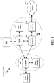
- FIG. 1 is a diagram illustrating an LTE network architecture 100.
- the LTE network architecture 100 may be referred to as an Evolved Packet System (EPS) 100.
- the EPS 100 may include one or more user equipment (UE) 102, an Evolved UMTS Terrestrial Radio Access Network (E-UTRAN) 104, an Evolved Packet Core (EPC) 110, a Home Subscriber Server (HSS) 120, and an Operator's IP Services 122.
- the EPS can interconnect with other access networks, but for simplicity those entities/interfaces are not shown.
- the EPS provides packet-switched services, however, as those skilled in the art will readily appreciate, the various concepts presented throughout this disclosure may be extended to networks providing circuit-switched services.
- the E-UTRAN includes the evolved Node B (eNB) 106 and other eNBs 108.
- the eNB 106 provides user and control planes protocol terminations toward the UE 102.
- the eNB 106 may be connected to the other eNBs 108 via a backhaul (e.g., an X2 interface).
- the eNB 106 may also be referred to as a base station, a base transceiver station, a radio base station, a radio transceiver, a transceiver function, a basic service set (BSS), an extended service set (ESS), or some other suitable terminology.
- the eNB 106 provides an access point to the EPC 110 for a UE 102.
- Examples of UEs 102 include a cellular phone, a smart phone, a session initiation protocol (SIP) phone, a laptop, a personal digital assistant (PDA), a satellite radio, a global positioning system, a multimedia device, a video device, a digital audio player (e.g., MP3 player), a camera, a game console, or any other similar functioning device.
- SIP session initiation protocol
- PDA personal digital assistant
- the UE 102 may also be referred to by those skilled in the art as a mobile station, a subscriber station, a mobile unit, a subscriber unit, a wireless unit, a remote unit, a mobile device, a wireless device, a wireless communications device, a remote device, a mobile subscriber station, an access terminal, a mobile terminal, a wireless terminal, a remote terminal, a handset, a user agent, a mobile client, a client, or some other suitable terminology.
- the eNB 106 is connected by an S1 interface to the EPC 110.
- the EPC 110 includes a Mobility Management Entity (MME) 112, other MMEs 114, a Serving Gateway 116, and a Packet Data Network (PDN) Gateway 118.
- MME Mobility Management Entity
- PDN Packet Data Network
- the MME 112 is the control node that processes the signaling between the UE 102 and the EPC 110.
- the MME 112 provides bearer and connection management. All user IP packets are transferred through the Serving Gateway 116, which itself is connected to the PDN Gatewav 118.
- the PDN Gatewav 118 provides UE IP address allocation as well as other functions.
- the PDN Gateway 118 is connected to the Operator's IP Services 122.
- the Operator's IP Services 122 may include the Internet, an Intranet, an IP Multimedia Subsystem (IMS), and a PS Streaming Service (PSS).
- IMS IP Multimedia Subsystem
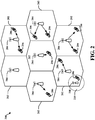
- FIG. 2 is a diagram illustrating an example of an access network 200 in an LTE network architecture.
- the access network 200 is divided into a number of cellular regions (cells) 202.
- One or more lower power class eNBs 208 may have cellular regions 210 that overlap with one or more of the cells 202.
- the lower power class eNB 208 may be a femto cell (e.g., home eNB (HeNB)), pico cell, micro cell, or remote radio head (RRH).
- HeNB home eNB
- RRH remote radio head
- the macro eNBs 204 are each assigned to a respective cell 202 and are configured to provide an access point to the EPC 110 for all the UEs 206 in the cells 202.
- the eNBs 204 are responsible for all radio related functions including radio bearer control, admission control, mobility control, scheduling, security, and connectivity to the serving gateway 116.
- the modulation and multiple access scheme employed by the access network 200 may vary depending on the particular telecommunications standard being deployed.
- OFDM is used on the DL
- SC-FDMA is used on the UL to support both frequency division duplexing (FDD) and time division duplexing (TDD).
- FDD frequency division duplexing
- TDD time division duplexing
- FDD frequency division duplexing
- TDD time division duplexing
- EV-DO Evolution-Data Optimized
- UMB Ultra Mobile Broadband
- EV-DO and UMB are air interface standards promulgated by the 3rd Generation Partnership Project 2 (3GPP2) as part of the CDMA2000 family of standards and employs CDMA to provide broadband Internet access to mobile stations. These concepts may also be extended to Universal Terrestrial Radio Access (UTRA) employing Wideband-CDMA (W-CDMA) and other variants of CDMA, such as TD-SCDMA; Global System for Mobile Communications (GSM) employing TDMA; and Evolved UTRA (E-UTRA), IEEE 802.11 (Wi-Fi), IEEE 802.16 (WiMAX), IEEE 802.20, and Flash-OFDM employing OFDMA.
- UTRA E-UTRA.
- UMTS LTE and GSM are described in documents from the 3GPP organization.
- CDMA2000 and UMB are described in documents from the 3GPP2 organization. The actual wireless communication standard and the multiple access technology employed will depend on the specific application and the overall design constraints imposed on the system.
- the eNBs 204 may have multiple antennas supporting MIMO technology.
- MIMO technology enables the eNBs 204 to exploit the spatial domain to support spatial multiplexing, beamforming, and transmit diversity.
- Spatial multiplexing may be used to transmit different streams of data simultaneously on the same frequency.
- the data steams may be transmitted to a single UE 206 to increase the data rate or to multiple UEs 206 to increase the overall system capacity. This is achieved by spatially precoding each data stream (i.e., applying a scaling of an amplitude and a phase) and then transmitting each spatially precoded stream through multiple transmit antennas on the DL.
- the spatially precoded data streams arrive at the UE(s) 206 with different spatial signatures, which enables each of the UE(s) 206 to recover the one or more data streams destined for that UE 206.
- each UE 206 transmits a spatially precoded data stream, which enables the eNB 204 to identify the source of each spatially precoded data stream.
- Beamforming may be used to focus the transmission energy in one or more directions. This may be achieved by spatially precoding the data for transmission through multiple antennas. To achieve good coverage at the edges of the cell, a single stream beamforming transmission may be used in combination with transmit diversity.
- OFDM is a spread-spectrum technique that modulates data over a number of subcarriers within an OFDM symbol.
- the subcarriers are spaced apart at precise frequencies. The spacing provides "orthogonality" that enables a receiver to recover the data from the subcarriers.
- a guard interval e.g., cyclic prefix
- the UL may use SC-FDMA in the form of a DFT-spread OFDM signal to compensate for high peak-to-average power ratio (PAPR).
- PAPR peak-to-average power ratio
- FIG. 3 is a diagram 300 illustrating an example of a DL frame structure in LTE.
- a frame (10 ms) mav be divided into 10 eauallv sized sub-frames. Each sub-frame may include two consecutive time slots.
- a resource grid may be used to represent two time slots, each time slot including a resource block.
- the resource grid is divided into multiple resource elements.
- a resource block contains 12 consecutive subcarriers in the frequency domain and, for a normal cyclic prefix in each OFDM symbol, 7 consecutive OFDM symbols in the time domain, or 84 resource elements.
- For an extended cyclic prefix a resource block contains 6 consecutive OFDM symbols in the time domain and has 72 resource elements.
- the DL-RS include Cell-specific RS (CRS) (also sometimes called common RS) 302 and UE-specific RS (UE-RS) 304.
- UE-RS 304 are transmitted only on the resource blocks upon which the corresponding physical DL shared channel (PDSCH) is mapped.
- PDSCH physical DL shared channel
- the number of bits carried by each resource element depends on the modulation scheme. Thus, the more resource blocks that a UE receives and the higher the modulation scheme, the higher the data rate for the UE.
- FIG. 4 is a diagram 400 illustrating an example of an UL frame structure in LTE.
- the available resource blocks for the UL may be partitioned into a data section and a control section.
- the control section may be formed at the two edges of the system bandwidth and may have a configurable size.
- the resource blocks in the control section may be assigned to UEs for transmission of control information.
- the data section may include all resource blocks not included in the control section.
- the UL frame structure results in the data section including contiguous subcarriers, which may allow a single UE to be assigned all of the contiguous subcarriers in the data section.
- a UE may be assigned resource blocks 410a, 410b in the control section to transmit control information to an eNB.
- the UE may also be assigned resource blocks 420a, 420b in the data section to transmit data to the eNB.
- the UE may transmit control information in a physical UL control channel (PUCCH) on the assigned resource blocks in the control section.
- the UE may transmit only data or both data and control information in a physical UL shared channel (PUSCH) on the assigned resource blocks in the data section.
- a UL transmission may span both slots of a subframe and may hop across frequency.
- a set of resource blocks may be used to perform initial system access and achieve UL synchronization in a physical random access channel (PRACH) 430.
- the PRACH 430 carries a random sequence and cannot carry any UL data/signaling.
- Each random access preamble occupies a bandwidth corresponding to six consecutive resource blocks.
- the starting frequency is specified by the network. That is, the transmission of the random access preamble is restricted to certain time and frequency resources. There is no frequency hopping for the PRACH.
- the PRACH attempt is carried in a single subframe (1 ms) or in a sequence of few contiguous subframes and a UE can make only a single PRACH attempt per frame (10 ms).
- FIG. 5 is a diagram 500 illustrating an example of a radio protocol architecture for the user and control planes in LTE.
- the radio protocol architecture for the UE and the eNB is shown with three layers: Layer 1, Layer 2, and Layer 3.
- Layer 1 (L1 layer) is the lowest layer and implements various physical layer signal processing functions.
- the L1 layer will be referred to herein as the physical layer 506.
- Layer 2 (L2 layer) 508 is above the physical layer 506 and is responsible for the link between the UE and eNB over the physical layer 506.
- the L2 layer 508 includes a media access control (MAC) sublayer 510, a radio link control (RLC) sublayer 512, and a packet data convergence protocol (PDCP) 514 sublayer, which are terminated at the eNB on the network side.
- MAC media access control
- RLC radio link control
- PDCP packet data convergence protocol
- the UE may have several upper layers above the L2 layer 508 including a network layer (e.g., IP layer) that is terminated at the PDN gateway 118 on the network side, and an application layer that is terminated at the other end of the connection (e.g., far end UE, server, etc.).
- IP layer e.g., IP layer
- the PDCP sublayer 514 provides multiplexing between different radio bearers and logical channels.
- the PDCP sublayer 514 also provides header compression for upper layer data packets to reduce radio transmission overhead, security by ciphering the data packets, and handover support for UEs between eNBs.
- the RLC sublayer 512 provides segmentation and reassembly of upper layer data packets, retransmission of lost data packets, and reordering of data packets to compensate for out-of-order reception due to hybrid automatic repeat request (HARQ).
- HARQ hybrid automatic repeat request
- the MAC sublayer 510 provides multiplexing between logical and transport channels.
- the MAC sublayer 510 is also responsible for allocating the various radio resources (e.g., resource blocks) in one cell among the UEs.
- the MAC sublayer 510 is also responsible for HARQ operations.
- the radio protocol architecture for the UE and eNB is substantially the same for the physical layer 506 and the L2 layer 508 with the exception that there is no header compression function for the control plane.
- the control plane also includes a radio resource control (RRC) sublayer 516 in Layer 3 (L3 layer).
- RRC sublayer 516 is responsible for obtaining radio resources (i.e., radio bearers) and for configuring the lower layers using RRC signaling between the eNB and the UE.
- FIG. 6 is a block diagram of an eNB 610 in communication with a UE 650 in an access network.
- upper layer packets from the core network are provided to a controller/processor 675.
- the controller/processor 675 implements the functionality of the L2 layer.
- the controller/processor 675 provides header compression, ciphering, packet segmentation and reordering, multiplexing between logical and transport channels, and radio resource allocations to the UE 650 based on various priority metrics.
- the controller/processor 675 is also responsible for HARQ operations, retransmission of lost packets, and signaling to the UE 650.
- the transmit (TX) processor 616 implements various signal processing functions for the L1 layer (i.e., physical layer).
- the signal processing functions includes coding and interleaving to facilitate forward error correction (FEC) at the UE 650 and mapping to signal constellations based on various modulation schemes (e.g., binary phase-shift keying (BPSK), quadrature phase-shift keying (QPSK), M-phase-shift keying (M-PSK), M-quadrature amplitude modulation (M-QAM)).
- FEC forward error correction
- BPSK binary phase-shift keying
- QPSK quadrature phase-shift keying
- M-PSK M-phase-shift keying
- M-QAM M-quadrature amplitude modulation
- Each stream is then mapped to an OFDM subcarrier, multiplexed with a reference signal (e.g., pilot) in the time and/or frequency domain, and then combined together using an Inverse Fast Fourier Transform (IFFT) to produce a physical channel carrying a time domain OFDM symbol stream.
- the OFDM stream is spatially precoded to produce multiple spatial streams.
- Channel estimates from a channel estimator 674 may be used to determine the coding and modulation scheme, as well as for spatial processing.
- the channel estimate may be derived from a reference signal and/or channel condition feedback transmitted by the UE 650.
- Each spatial stream is then provided to a different antenna 620 via a separate transmitter 618TX.
- Each transmitter 618TX modulates an RF carrier with a respective spatial stream for transmission.
- each receiver 654RX receives a signal through its respective antenna 652.
- Each receiver 654RX recovers information modulated onto an RF carrier and provides the information to the receive (RX) processor 656.
- the RX processor 656 implements various signal processing functions of the L1 layer.
- the RX processor 656 performs spatial processing on the information to recover any spatial streams destined for the UE 650. If multiple spatial streams are destined for the UE 650, they may be combined by the RX processor 656 into a single OFDM symbol stream.
- the RX processor 656 then converts the OFDM symbol stream from the time-domain to the frequency domain using a Fast Fourier Transform (FFT).
- FFT Fast Fourier Transform
- the symbols on each subcarrier, and the reference signal, is recovered and demodulated by determining the most likely signal constellation points transmitted by the eNB 610. These soft decisions may be based on channel estimates computed by the channel estimator 658. The soft decisions are then decoded and deinterleaved to recover the data and control signals that were originally transmitted by the eNB 610 on the physical channel. The data and control signals are then provided to the controller/processor 659.
- the controller/processor 659 implements the L2 layer.
- the controller/processor can be associated with a memory 660 that stores program codes and data.
- the memory 660 may be referred to as a computer-readable medium.
- the controller/processor 659 provides demultiplexing between transport and logical channels, packet reassembly, deciphering, header decompression, control signal processing to recover upper layer packets from the core network.
- the upper layer packets are then provided to a data sink 662, which represents all the protocol layers above the L2 layer.
- Various control signals may also be provided to the data sink 662 for L3 processing.
- the controller/processor 659 is also responsible for error detection using an acknowledgement (ACK) and/or negative acknowledgement (NACK) protocol to support HARQ operations.
- ACK acknowledgement
- NACK negative acknowledgement
- a data source 667 is used to provide upper layer packets to the controller/processor 659.
- the data source 667 represents all protocol layers above the L2 layer.
- the controller/processor 659 implements the L2 layer for the user plane and the control plane by providing header compression, ciphering, packet segmentation and reordering, and multiplexing between logical and transport channels based on radio resource allocations by the eNB 610.
- the controller/processor 659 is also responsible for HARQ operations, retransmission of lost packets, and signaling to the eNB 610.
- Channel estimates derived by a channel estimator 658 from a reference signal or feedback transmitted by the eNB 610 may be used by the TX processor 668 to select the appropriate coding and modulation schemes, and to facilitate spatial processing.
- the spatial streams generated by the TX processor 668 are provided to different antenna 652 via separate transmitters 654TX. Each transmitter 654TX modulates an RF carrier with a respective spatial stream for transmission.
- the UL transmission is processed at the eNB 610 in a manner similar to that described in connection with the receiver function at the UE 650.
- Each receiver 618RX receives a signal through its respective antenna 620.
- Each receiver 618RX recovers information modulated onto an RF carrier and provides the information to a RX processor 670.
- the RX processor 670 may implement the L1 layer.
- the controller/processor 675 implements the L2 layer.
- the controller/processor 675 can be associated with a memory 676 that stores program codes and data.
- the memory 676 may be referred to as a computer-readable medium.
- the control/processor 675 provides demultiplexing between transport and logical channels, packet reassembly, deciphering, header decompression, control signal processing to recover upper layer packets from the UE 650.
- Upper layer packets from the controller/processor 675 may be provided to the core network.
- the controller/processor 675 is also responsible for error detection using an ACK and/or NACK protocol to support HARQ operations.
- FIG. 7 is a simplified schematic of a wireless network, which may comprise an LTE network.
- downlink transmission modes may be semi-statically configured for a UE 704.
- the transmission of PDSCH 706 may include a UE-specific reference signal, such as DM-RS.
- eNB 702 scheduling may determine whether UE 704 operates in single user MIMO (SU-MIMO) mode or whether it is co-scheduled with another UE in multi-user MIMO (MU-MIMO) operation.
- UE 702 may be dynamically switched between SU-MIMO and MU-MIMO based on scheduling requirements determined by eNB 702.
- the UE 704 can be configured to use a PMI for UE 704 channel state information feedback.
- the PMI typically comprises a signal fed back by the UE 704 to the eNB 702, which is related to the current MIMO operation/mode and corresponds to the index of the precoder within a codebook shared bv the UE 704 and eNB 702.
- the precoder index is typically selected to maximize the aggregate number of data bits which could be received across all downlink spatial transmission layers.
- PMI is associated with a RI that is signaled to the eNB 702 by the UE 704 and corresponds to the number of usable transmission layers the UE determines can be used for spatial multiplexing (based on an estimate of the downlink channel determined by the UE 704).
- the RI enables the eNB 702 to adapt PDSCH transmissions 706 based on the UE 704 channel estimate.
- the type of PMI supported may depend on the type of channel state information (CSI) feedback 708.
- CSI feedback 708 may be reported periodically for wideband single PMI mode and/or for a UE-selected single PMI mode.
- CSI feedback 708 may be reported aperiodically for a wideband multiple PMI mode, UE-selected multiple PMI mode, and/or for single PMI modes configured at higher protocol layers.
- RI is typically reported to maximize downlink throughput and the reported PMI is conditioned on the reported RI.
- the RI reported by a UE 704 may not be aligned with the intended rank for scheduling of PDSCH transmission 706 by the eNB 702 to the UE 704.
- UE 704 may report rank 2, while the eNB 702 may schedule, or intend to schedule PDSCH for the UE 704 using rank 1, and/or using MU-MIMO operation.
- the precoding information obtained from a first PMI conditioned on the first reported RI may not be optimal for a second reported RI.
- the number of PMIs included in the codebook may vary by rank, and a PMI index reported for a first rank may not necessarily be equivalent to a PMI index for the codebook entries for a second rank.
- a UE 704 may report a PMI and RI combination that targets a balanced performance among different ranks.
- a UE 704 may report a non-optimal PMI for rank 2, which may provide a variance of 5% from optimal rank 2 performance in one example, but which achieves significantly better performance in rank 1, when a rank-1 precoder is extracted from the optimal rank 2 PMI.
- This approach can produce a reasonable tradeoff between SU-MIMO and MU-MIMO performance.
- alternative approaches disclosed herein enable multiple rank reports and reduce the need for tradeoffs in PMI selection. That is, when selecting a PMI to report, the UE may pick a PMI that provides the best overall performance over multiple ranks, instead of the best performance at a specific rank.
- Some embodiments provide multi-rank feedback reporting that can enhance SU-MIMO and MU-MIMO operation.
- a PMI corresponding to each of a plurality of different ranks is provided in feedback with different frequency granularities.
- one PMI may correspond to a wideband rank, while another PMI corresponds to a sub-band specific rank.
- a rank-1 PMI may be provided on a subband-level to enhance MU-MIMO beam selection, while a single wideband rank-2 or higher PMI may be sufficient for SU-MIMO operation.
- rank-specific reports may be triggered implicitly by requesting such reports on certain subframes.
- One or more subframe sets may be defined that are associated with a certain rank to be reported by the UE 704.
- the UE 704 reports CSI feedback 708 for the rank associated with the subframe set to which the reference subframe belongs.
- Subframe sets may also be associated with multiple ranks and CSI feedback 708 for multiple ranks may be conveyed in the same report using, for example, aperiodic feedback on PUSCH.
- the UE may also downselect and report CSI only for a subset of the multiple ranks.
- a rank-specific report may include PMI and CQI values that are associated with a RI.
- codebook subset restriction may be configured separately for each of the multi-rank reports.
- the usage of one or more PMIs may be restricted to obtain increased download throughput and reduce inter-cell interference.
- a codebookSubsetRestriction parameter may be configured separately for each of a plurality of rank reports.
- an existing bitmap may be modified to account for multi-rank operation. For example, one bitmap may specify which PMIs are disabled on a per-rank basis. A second bitmap may specify, for each of the multi-rank reports, which ranks are admissible for the report.
- rank-specific reports may be dynamically triggered. Additional bits in the DCI format may dynamically indicate to the UE 704 which rank is used for CSI reporting 708. The additional bits may also indicate whether the UE 704 should provide a single rank report or multiple rank reports. Rank-specific reports mav be dvnamicallv triggered using a 2-bit field assigned for aperiodic CSI triggering in a carrier aggregation context. For example, the 2-bit field may be used to indicate one of three possible combinations.
- additional aperiodic CSI feedback modes using PUSCH may be employed by a UE 704 to provide feedback in two separate CSI reports. For example, one report may be conditioned on measurements associated with a set of UE 704 selected subbands, while the other may be conditioned on measurements associated with all available subbands.
- UE 704 selected subbands may be conveyed to the eNB 702 by the UE 704 through a bitmap.
- UEs may provide CSI feedback 708 under different RIs for the UE-selected preferred subbands and all subbands, respectively.
- UE 704 may report rank 1 for the UE-selected subbands to improve MU-MIMO performance, while PMI/CQI information corresponding to a rank higher than rank 1 may be conveyed on a wideband basis.
- the bitmap used to convey the subband selection may be adapted and/or enhanced to permit more flexibility in conveying preferred subbands.
- multi-rank support may be provided for additional periodic CSI feedback modes.
- periodic reporting modes When periodic reporting modes are used, a UE 704 may report CSI according to a predetermined timeline that is signaled to the UE 704 by RRC configuration 710.
- the RI and, where reported, precoder type feedback or precoder type indicators (PTI) are typically reported in separate reporting instances.
- PMI/CQI reports are typically conditioned on the last transmitted RI and PTI, if reported.
- the payload for periodic reporting may be limited to a predefined number of bits. Accordingly, multiple separate periodic reporting instances may be configured for multi-rank reporting. Each periodic reporting instance may be tied to a certain RI that is configured through RRC signaling 710 as part of the periodic CSI reporting configuration.
- a rank-restriction bitmap may be employed to limit the admissible ranks that can be reported by the UE 704.
- RI transmission may be selectively suppressed in CSI reporting 708, whereby the RI may or may not be transmitted by the UE 704.
- RI may be transmitted when the multi-rank feedback allows the UE 704 to select from more than one admissible value.
- the RI report may be omitted. If PTI is to be reported together with RI, then the report may be sent, or only the RI field may be omitted.
- rank-specific reporting may be based on coordinated multipoint transmission (CoMP) CSI reporting instances.
- CoMP coordinated multipoint transmission
- CSI reporting 708 may be based on separately configured channel measurement resources (CMRs) and interference measurement resources (IMRs).
- CMR channel measurement resources
- IMRs interference measurement resources
- a CMR may comprise a non-zero power CSI-RS resource that is used by the UE 704 to perform channel estimation.
- Multiple CMRs may be supported and may comprise the CoMP measurement set.
- An IMR may comprise zero-power and/or non-zero power CSI-RS resources that are used by the UE 704 to perform interference estimation.
- One or more IMRs may be supported.
- multiple CSI feedback 708 instances may be available through CoMP, and each CSI feedback 708 instance may be defined by a linkage of one CMR and one IMR.
- rank-restriction may be specified for each CSI feedback 708 instance.
- the UE 704 may be restricted to consider only a subset of possible RI values for a specific CSI feedback 708 instance.
- One or more CSI reports may be characterized by such RI restriction.
- a rank-restriction bitmap may be defined to signal the admissible rank values to the UE 704 when only a single CSI report comprising a UE-selected RI value is to be reported in CSI feedback 708.
- the rank-restriction bitmap may be extended to allow multiple rank restrictions, each corresponding to a separate CSI report, when multiple CSI reports are desired. For example, if two CSI reports are desired one may be restricted to rank 1 only and another may allow for rank 1 or higher.
- Some embodiments provide interdependency among different CSI reporting configurations. For example, if the rank selected by a UE 704 for one reporting configuration (e.g., in the case of rank 1 or higher) is the same as for another CSI reporting configuration, then one report may be omitted, since the reports may contain identical information. In some embodiments, the report may be sent if PMI/CQI differs between the configurations, such as when a different IMR is used to generate the report and only the RI are the same.
- certain conditions may be specified across the UE-selected RIs for different reporting instances.
- the UE 704 may be required to select the RI associated with one reporting configuration to be no larger than the RI associated with another reporting configuration, thereby facilitating a trade-off between SU-MIMO and MU-MIMO performance.
- the rank reported by the UE 704 for MU-MIMO may be constrained to be no larger than the rank reported for SU-MIMO.
- rank-specific reporting using a CoMP CSI reporting instance may be combined with dynamic and/or semi-static signaling, such as subframe sets, dynamic triggering, etc.
- dynamic and/or semi-static signaling such as subframe sets, dynamic triggering, etc.
- multiple rank-restricted reporting configurations may be accomplished by configuring separate CSI feedback instances that map to corresponding CMR and IMR. A separately configured CSI reporting configuration may be required for such rank-restricted reporting.
- Rank-restriction offers various advantages when used with CoMP in addition to general advantages associated with performance tradeoff between SU-MIMO and MU-MIMO.
- Rank-restriction may enable the network to schedule a certain rank on certain subframes. For example, the network can take steps to schedule with rank 1 on one set of subframes when the UE 704 is restricted to reporting rank 1 on the set of subframes, such as "unclean" subframes where the macro is active. This may improve performance for another class of UEs 704 that is impacted by the macro interference, e.g., UEs 704 in the cell-range expansion region of an adjacent pico cell.
- wideband and sub-band CQIs corresponding to additional RI/PMIs may be reported.
- additional reporting may be performed primarily using aperiodic CSI reports when periodic CSI reporting is subject to limitations on CSI payload.
- CSI payload may be limited to 11 bits per report while aperiodic CSI reporting may have more relaxed limitations on CSI payload in which the payload size may be limited on a per carrier basis to approximately 70 bits for a 20 MHz system.
- the limit on payload size for aperiodic CSI may be increased to 300+ bits.
- Another approach for supporting rank-restricted CSI feedback for CoMP is to define a reference CSI process. For example, if two CSI processes are desired for performing CSI reporting with the same rank, one of the two CSI processes may be designated as a "reference process.” The other of the two CSI processes linked to the reference process would then be constrained to selecting the same rank as that of the reference process. The designation of the reference process and the linked process may be performed via RRC configuration.
- the reference process may be associated with RI feedback and subband selection for PUCCH mode 2-1.
- anv CSI process linked to a reference process may simply reuse the subband selection of the reference process and perform a computation of remaining feedback metrics (e.g., PMI, CQI) conditioned on the "inherited" properties of the reference process.
- the definition of a reference process impacts the feedback timeline for periodic feedback reporting.
- the feedback reporting timeline may include wideband and/or subband PMI/CQI reports that are conditioned on previous RI and/or PMI reports.
- RI is reported with a periodicity that is an integer multiple of the time period it takes to cycle across all PMI/CQI reports of the system bandwidth. For example, in PUCCH mode 2-1 such cycling is performed across bandwidth parts. In the absence of a reference process, the rank can therefore only change after an entire cycle has been completed.
- the RI periodicity or offset are configured in a way such that the RI of the reference process changes while the linked process undergoes a cycle of PMI/CQI reports.
- the UE should immediately start using the latest reported RI value or whether it should first complete the PMI/CQI reporting cycle before doing so.
- the UE were to immediately start using the updated RI value, several complications arise including inconsistencies between PMI reports (conditioning on the old vs. the new RI) and CQI reports that are supposed to be conditioned on an incompatible combination of RI and PMI reports. Similar issues arise for the PTI selection.
- the aforementioned incompatibilities may be resolved by restricting the configuration of the reporting timelines between the reference CSI process and its one or more linked CSI processes. For example, by carefully selecting the RI reporting period and the periodicities of RI/PMI reporting, the reporting timelines of reference/linked processes can be aligned such that the RI, subband selection, or PTI changes do not lead to incompatible conditioning for the linked CSI process (e.g., by having the RI reports occur in consecutive or close-by subframes).
- the aforementioned incompatibility may be avoided by not immediately applying updated RI, PTI, or subband metrics of the reference process. Instead, if RI, PTI, or subband metrics change while the linked process is within a PMI/COI reporting cycle, the UE will continue based on the old RI. PTI or subband metrics. Only after the cycle has been completed, the UE will use the updated RI, PTI or subband information of the reference process.
- the RI, PTI, or subband selection between the reference and linked processes may be linked directly, rather than to condition the PMI/CQI computation of the linked processes to the RI, PTI, or subband selection of the reference process.
- the RI, PTI, or subband selection changes only at times that would anyway allow the linked process to change the corresponding values.
- the PMI/CQI computation of the linked process would continue to be based only on the RI, PTI, and subband selection of the linked process (and not the reference process).
- the RI, PTI, and subband selection of the linked process would be tied directly to the RI, PTI, and subband selection of the reference process.
- the CSI reference process has only been discussed with respect to subband selection in PUCCH mode 2-1 and for the RI, it may be extended to other reporting modes such as PUSCH mode 2-2, and other feedback metrics such as the Precoding Type Indicator (PTI).
- PUSCH mode 2-2 a preferred set of subbands is selected for aperiodic reporting.
- the UE may be configured to reuse the preferred subbands selection of the reference process for the linked process.
- the extension to PTI which is used for periodic reporting in PUCCH mode 2-1 (with 8Tx configured)
- the PTI selection from the reference process may be reused by the linked process. This also has the benefit of the reporting timelines of wideband and subband PMI/CQI being aligned between the reference and the linked CSI processes.
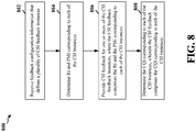
- FIG. 8 is a flow chart 800 of a method of wireless communication. The method may be performed by a UE 704.
- the UE 704 receives feedback configuration information that defines a plurality of CSI feedback instances. Each CSI feedback instance may be conditioned on one of a set of admissible rank values. In some embodiments, receiving the feedback configuration includes receiving a bitmap specifying rank values that are admissible for each CSI feedback instance. In some embodiments, receiving the feedback configuration includes conditioning each CSI feedback instance by the set of admissible rank values by determining RI among the rank values that are specified to be admissible in the bitmap. In some embodiments, receiving the feedback configuration includes receiving a bitmap specifying combinations of RI and PMI that are admissible for each CSI feedback instance, and the RI and PMI may be determined for combinations which are specified as admissible in the bitmap.
- receiving the feedback configuration includes receiving signaling that associates each of one or more sets of subframes with one or more rank values. In some embodiments, receiving the feedback configuration includes determining the set of admissible rank values for each CSI instance based on the one or more rank values associated with the subframe set which includes a reference subframe. In some embodiments, the feedback configuration information identifies the rank used for reporting the CSI feedback 708.
- the feedback configuration information identifies a plurality of ranks for which RI and PMI are reported in the CSI feedback 708 through additional bits in a DCI format requesting an aperiodic feedback report.
- the feedback information may identify the set of admissible rank values through RRC-based configuration for periodic feedback reporting.
- the feedback configuration information disables one or more PMIs in a codebook for each CSI feedback instance.
- the UE 704 determines a RI and a PMI corresponding to each of the CSI instances.
- the PMI is determined with a frequency granularity for the one or more CSI feedback instances.
- the frequency granularity may be determined based on a rank selected for the one or more CSI feedback instances.
- the PMI is determined and reported with a frequency granularity for a selected CSI feedback instance, the frequency granularity being determined based on a rank selected for the one or more CSI feedback instances.
- the frequency with which PMI is determined and reported for one of the CSI feedback instances is selected based on a rank corresponding to the one CSI feedback instance.
- the UE 704 provides CSI feedback 708 for one or more of the CSI feedback instances.
- the CSI feedback 708 comprises the RI and the PMI corresponding to each of the CSI instances.
- Providing CSI feedback 708 for the one or more ranks may include determining a set of subbands from a plurality of subbands, providing a first CSI feedback report corresponding to the set of subbands, and providing a second CSI feedback report corresponding to the plurality of subbands.
- the RI and the PMI corresponding to each of the CSI instances are determined based on channel measurements on a channel measurement resource and interference measurements on an interference measurement resource.
- the UE 704 determines a CQI corresponding to each of the CSI instances.
- the CSI feedback 708 may comprise the CQI corresponding to each of the CSI instances.
- FIG. 9 is a conceptual data flow diagram 900 illustrating the data flow between different modules/means/components in an exemplary apparatus 902.
- the apparatus may be a UE 704.
- the apparatus includes a receiving module 904 that receives feedback configuration information defining a plurality of CSI feedback instances, a module 906 that determines RI and PMI corresponding to the CSI instances, a module 908 that determines CQI corresponding to the CSI instances, and a transmission module 910 that transmits CSI feedback 708 to eNB 950.
- the apparatus may include additional modules that perform each of the steps of the algorithm in the aforementioned flow charts of FIG. 8 .
- each step in the aforementioned flow charts of FIG. 8 may be performed by a module and the apparatus may include one or more of those modules.
- the modules may be one or more hardware components specifically configured to carry out the stated processes/algorithm, implemented by a processor configured to perform the stated processes/algorithm, stored within a computer-readable medium for implementation by a processor, or some combination thereof.
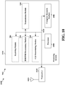
- FIG. 10 is a diagram 1000 illustrating an example of a hardware implementation for an apparatus 902' employing a processing system 1014.
- the processing system 1014 may be implemented with a bus architecture, represented generally by the bus 1024.
- the bus 1024 may include any number of interconnecting buses and bridges depending on the specific application of the processing system 1014 and the overall design constraints.
- the bus 1024 links together various circuits including one or more processors and/or hardware modules, represented by the processor 1004, the modules 904, 906, 908, 910, and the computer-readable medium 1006.
- the bus 1024 may also link various other circuits such as timing sources, peripherals, voltage regulators, and power management circuits, which are well known in the art, and therefore, will not be described anv further.
- the processing system 1014 may be coupled to a transceiver 1010.
- the transceiver 1010 is coupled to one or more antennas 1020.
- the transceiver 1010 provides a means for communicating with various other apparatus over a transmission medium.
- the processing system 1014 includes a processor 1004 coupled to a computer-readable medium 1006.
- the processor 1004 is responsible for general processing, including the execution of software stored on the computer-readable medium 1006.
- the software when executed by the processor 1004, causes the processing system 1014 to perform the various functions described supra for any particular apparatus.
- the computer-readable medium 1006 may also be used for storing data that is manipulated by the processor 1004 when executing software.
- the processing system further includes at least one of the modules 904, 906, 908, and 910.
- the modules may be software modules running in the processor 1004, resident/stored in the computer readable medium 1006, one or more hardware modules coupled to the processor 1004, or some combination thereof.
- the processing system 1014 may be a component of the UE 650 and may include the memory 660 and/or at least one of the TX processor 668, the RX processor 656, and the controller/processor 659.
- the apparatus 902/902' for wireless communication includes means 904 for means for receiving feedback configuration information that defines a plurality of CSI feedback instances, means 906 for determining RI and PMI corresponding to each of the CSI instances, means 908 for determining a CQI corresponding to each of the CSI instances, and means 910 for providing CSI feedback 708 for one or more of the CSI feedback instances.
- Each CSI feedback instance may be conditioned on one of a set of admissible rank values and the CSI feedback 708 may comprise the RI and the PMI corresponding to each of the CSI instances.
- the CSI feedback 708 may comprise the CQI corresponding to each of the CSI instances.
- PMI and RI may be determined with a frequency granularity for CSI feedback instances whereby the frequency granularity is determined based on a rank selected for the one or more CSI feedback instances.
- the feedback configuration information may include a bitmap specifying rank values that are admissible for each CSI feedback instance.
- the feedback configuration information may condition each CSI feedback instance by the set of admissible rank values by determining RI among the rank values that are specified to be admissible in the bitmap.
- the means for receiving the feedback configuration information may receive a bitmap specifying combinations of RI and PMI that are admissible for each CSI feedback instance, and may determine the RI and PMI for combinations which are specified as admissible in the bitmap.
- the feedback configuration information may identify the rank used for reporting the CSI feedback 708.
- the feedback configuration information may identify a plurality of ranks for which RI and PMI are reported in the CSI feedback 708 through additional bits in a DCI format requesting an aperiodic feedback report.
- the feedback information may identify the set of admissible rank values through RRC-based configuration for periodic feedback reporting.
- the means for providing CSI feedback 708 for the one or more ranks may determine a set of subbands from a plurality of subbands, provide a first CSI feedback report corresponding to the set of subbands, and provide a second CSI feedback report corresponding to the plurality of subbands.
- the RI and the PMI corresponding to each of the CSI instances may be determined based on channel measurements on a channel measurement resource and interference measurements on an interference measurement resource.
- the feedback configuration information may disable one or more PMIs in a codebook for each CSI feedback instance.
- the aforementioned means may be one or more of the aforementioned modules of the apparatus 902 and/or the processing system 1014 of the apparatus 902' configured to perform the functions recited by the aforementioned means.
- the processing system 1014 may include the TX Processor 668, the RX Processor 656, and the controller/processor 659.
- the aforementioned means may be the TX Processor 668, the RX Processor 656, and the controller/processor 659 configured to perform the functions recited by the aforementioned means.
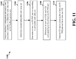
- FIG. 11 is a flow chart 1100 of a method of wireless communication. The method may be performed by a UE 704.
- the UE 704 receives feedback configuration information that associates a plurality of admissible rank value sets to channel state information (CSI) feedback process sets.
- Each admissible rank value set may include at least one rank indicator (RI) and precoding matrix indicator (PMI) pair (RI-PMI pair).
- An admissible rank value set may also exclude certain RI-PMI pairs.
- Each CSI feedback process set may include at least one CSI feedback process, and each CSI feedback process may be based on an admissible rank value set from the plurality of admissible rank value sets.
- the UE 704 determines a selected admissible rank value set based on the plurality of admissible rank value sets.
- the selected admissible rank value set includes a plurality of admissible rank values.
- the UE 704 may base the selection on signaling from a base station (e.g., base station 702).
- the selected admissible rank value set may be determined based on one or more sets of subframes for which a CSI report is scheduled.
- the UE 704 determines at least one RI-PMI pair corresponding to the selected admissible rank value set.
- a PMI of the determined at least one RI-PMI pair corresponds to a PMI providing optimal performance over a plurality of admissible rank values of the selected admissible rank value set.
- the UE 704 determines at least one channel quality indicator (CQI). Each CQI may correspond to one of the at least one RI-PMI pair.
- the UE 704 may transmit the CSI report including the at least one RI-PMI pair and the at least one CQI to the base station.
- the feedback configuration information identifies the plurality of admissible rank value sets for which the at least one RI-PMI pair is reported in the CSI report through additional bits in a downlink control information (DCI) format requesting an aperiodic feedback report.
- DCI downlink control information
- the UE 704 may receive the feedback configuration information by receiving a bitmap specifying an admissible rank value set associated to each CSI feedback process set, and conditioning each CSI feedback process set by the admissible rank value set by determining at least one RI from the admissible rank value set specified in the bitmap. Additionally or alternatively, the UE 704 may receive the feedback configuration information by receiving a bitmap specifying at least one admissible RI-PMI pair associated to each CSI feedback process set, wherein an RI and a PMI are determined for the at least one admissible RI-PMI pair specified in the bitmap.
- an RI and a PMI of at least one RI-PMI pair associated to each of the CSI feedback process sets are determined based on channel measurements on a channel measurement resource and interference measurements on an interference measurement resource.
- the feedback configuration information may disable one or more PMIs in a codebook for each CSI feedback process set.
- the PMI may be determined with a frequency granularity for the at least one CSI feedback process.
- the frequency granularity may be determined based on a rank value selected for the at least one CSI feedback process.
- the feedback configuration information may identify the admissible rank value sets through RRC-based configuration for periodic feedback reporting.
- the UE 704 may transmit the CSI report by determining a set of subbands from a plurality of subbands, providing a first CSI report corresponding to the set of subbands, and providing a second CSI report corresponding to the plurality of subbands.
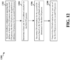
- FIG. 12 is a flow chart 1200 of a method of wireless communication. The method may be performed by a UE 704.
- the UE 704 receives feedback configuration signaling that defines at least a first channel state information (CSI) process and a second CSI process.
- the first CSI process may be designated as a reference CSI process for the second CSI process.
- the UE 704 determines at least one of a rank indicator (RI) or a subband selection for the first CSI process based on measurements associated with the first CSI process.
- RI rank indicator
- the UE 704 determines CSI information for the second CSI process based on the RI and/or subband selection determined for the first CSI process.
- the CSI information for the second CSI process may include at least one of a RI, a precoding matrix indicator (PMI), a channel quality indicator (CQI), a subband selection, or a precoding type indicator (PTI).
- the CSI information for the second CSI process may be further based on a PTI associated with the first CSI process when the PTI is configured for the first CSI process and when the CSI information for the second CSI process is based on the RI for the first CSI process.
- the PMI and CQI associated with the second CSI process are determined based on the RI and/or subband selection associated with the first CSI process.
- a PMI and CQI feedback timeline associated with a periodic reporting configuration of the second CSI process, are configured to avoid incompatible conditioning with respect to the RI and/or subband selection of the first CSI process.
- the PMI and CQI associated with the second CSI process are determined based on a last reported RI and/or last reported subband selection of the first CSI process that occurred on or before a start of a reporting cycle of the second CSI process.
- the PMI and CQI associated with the second CSI process are determined based on a last reported RI and/or last reported subband selection of the second CSI process.
- the RI and/or subband selection of the second CSI process is inherited from a last reported RI and/or subband selection of the first CSI process.
- the UE 704 transmits the CSI information for at least one of the first CSI process or the second CSI process.
- the first CSI process and the second CSI process are configured to use periodic or aperiodic feedback reporting.
- the second CSI process selects an associated set of preferred subbands to be the same as a set of preferred subbands determined for the first CSI process.
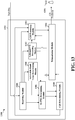
- FIG. 13 is a conceptual data flow diagram 1300 illustrating the data flow between different modules/means/components in an exemplary apparatus 1302.
- the apparatus may be a UE (e.g., UE 704).
- the apparatus includes a receiving module 1304, an RI/PMI determining module 1306, a CQI determining module 1308, an admissible rank value determining module 1310, a subband/PTI processing module 1312, a CSI processing module 1314, and a transmission module 1316.
- the receiving module 1304 receives feedback configuration information that associates a plurality of admissible rank value sets to channel state information (CSI) feedback process sets.
- Each admissible rank value set may include at least one rank indicator (RI) and precoding matrix indicator (PMI) pair (RI-PMI pair).
- An admissible rank value set may also exclude certain RI-PMI pairs.
- Each CSI feedback process set may include at least one CSI feedback process, and each CSI feedback process may be based on an admissible rank value set from the plurality of admissible rank value sets.
- the admissible rank value determining module 1310 determines a selected admissible rank value set based on the plurality of admissible rank value sets.
- the selected admissible rank value set includes a plurality of admissible rank values.
- the admissible rank value determining module 1310 may base the selection on signaling from a base station (e.g., base station 1350).
- the selected admissible rank value set may be determined based on one or more sets of subframes for which a CSI report is scheduled.
- the RI/PMI determining module 1306 determines at least one RI-PMI pair corresponding to the selected admissible rank value set.
- a PMI of the determined at least one RI-PMI pair corresponds to a PMI providing optimal performance over a plurality of admissible rank values of the selected admissible rank value set.
- the CQI determining module 1308 determines at least one channel quality indicator (CQI), wherein each CQI may correspond to one of the at least one RI-PMI pair.
- the transmission module 1316 may transmit to the base station 1350 the CSI report including the at least one RI-PMI pair (determined by the RI/PMI determining module 1306) and the at least one CQI (determined by the CQI determining module 1308).
- the feedback configuration information identifies the plurality of admissible rank value sets for which the at least one RI-PMI pair is reported in the CSI report through additional bits in a downlink control information (DCI) format requesting an aperiodic feedback report.
- DCI downlink control information
- the admissible rank value determining module 1310 may receive (via the receiving module 1304) the feedback configuration information by receiving a bitmap specifying an admissible rank value set associated to each CSI feedback process set. Accordingly, the RI/PMI determining module 1306 may condition each CSI feedback process set by the admissible rank value set by determining at least one RI from the admissible rank value set specified in the bitmap.
- the RI/PMI determining module 1306 may receive the feedback configuration information by receiving a bitmap specifying at least one admissible RI-PMI pair associated to each CSI feedback process set, wherein the RI/PMI determining module 1306 determines an RI and a PMI for the at least one admissible RI-PMI pair specified in the bitmap.
- the RI/PMI determining module 1306 determines an RI and a PMI of at least one RI-PMI pair associated to each of the CSI feedback process sets based on channel measurements on a channel measurement resource and interference measurements on an interference measurement resource.
- the feedback configuration information may disable one or more PMIs in a codebook for each CSI feedback process set.
- the RI/PMI determining module 1306 may determine the PMI with a frequency granularity for the at least one CSI feedback process.
- the frequency granularity may be determined based on a rank value selected for the at least one CSI feedback process.
- the feedback configuration information may identify the admissible rank value sets through RRC-based configuration for periodic feedback reporting.
- the transmission module 1316 may transmit the CSI report by determining (via the subband/PTI processing module 1312) a set of subbands from a plurality of subbands, providing a first CSI report corresponding to the set of subbands, and providing a second CSI report corresponding to the plurality of subbands.
- the receiving module 1304 receives feedback configuration signaling that defines at least a first channel state information (CSI) process and a second CSI process.
- the first CSI process may be designated as a reference CSI process for the second CSI process.
- the RI/PMI determining module 1306 may determines a rank indicator (RI) for the first CSI process based on measurements associated with the first CSI process.
- the subband/PTI processing module 1312 determines a subband selection for the first CSI process based on measurements associated with the first CSI process.
- the CSI processing module 1314 determines CSI information for the second CSI process based on the RI and/or subband selection determined for the first CSI process.
- the CSI information for the second CSI process may include at least one of a RI, a precoding matrix indicator (PMI), a channel quality indicator (CQI), a subband selection, or a precoding type indicator (PTI).
- the CSI information for the second CSI process may be further based on a PTI associated with the first CSI process when the PTI is configured for the first CSI process and when the CSI information for the second CSI process is based on the RI for the first CSI process.
- the RI/PMI determining module 1306 determines the PMI associated with the second CSI process based on the RI and/or subband selection associated with the first CSI process.
- the CQI determining module 1308 determines the CQI associated with the second CSI process based on the RI and/or subband selection associated with the first CSI process.
- a PMI and CQI feedback timeline, associated with a periodic reporting configuration of the second CSI process, are configured to avoid incompatible conditioning with respect to the RI and/or subband selection of the first CSI process.
- the RI/PMI determining module 1306 determines the PMI associated with the second CSI process based on a last reported RI and/or last reported subband selection of the first CSI process that occurred on or before a start of a reporting cycle of the second CSI process.
- the CQI determining module 1308 determines the CQI associated with the second CSI process based on a last reported RI and/or last reported subband selection of the first CSI process that occurred on or before a start of a reporting cycle of the second CSI process.
- the PMI and CQI associated with the second CSI process are determined (by the RI/PMI determining module 1306 and the CQI determining module 1308, respectively) based on a last reported RI and/or last reported subband selection of the second CSI process.
- the RI and/or subband selection of the second CSI process is inherited from a last reported RI and/or subband selection of the first CSI process.
- the CSI processing module 1314 transmits (via the transmission module 1316) the CSI information for at least one of the first CSI process or the second CSI process.
- the first CSI process and the second CSI process are configured to use aperiodic feedback reporting based on a physical uplink scheduling channel (PUSCH) mode 2-2, and the second CSI process selects an associated set of preferred subbands to be the same as a set of preferred subbands determined for the first CSI process.
- PUSCH physical uplink scheduling channel
- the apparatus may include additional modules that perform each of the steps of the algorithm in the aforementioned flow charts of FIGs. 11-12 . As such, each step in the aforementioned flow charts of FIGs. 11-12 may be performed by a module and the apparatus may include one or more of those modules.
- the modules may be one or more hardware components specifically configured to carry out the stated processes/algorithm, implemented by a processor configured to perform the stated processes/algorithm, stored within a computer-readable medium for implementation by a processor, or some combination thereof.
- FIG. 14 is a diagram 1400 illustrating an example of a hardware implementation for an apparatus 1302' employing a processing system 1414.
- the processing system 1414 may be implemented with a bus architecture, represented generally by the bus 1424.
- the bus 1424 mav include anv number of interconnecting buses and bridges depending on the specific application of the processing system 1414 and the overall design constraints.
- the bus 1424 links together various circuits including one or more processors and/or hardware modules, represented by the processor 1404, the modules 1304, 1306, 1308, 1310, 1312, 1314, 1316, and the computer-readable medium 1406.
- the bus 1424 may also link various other circuits such as timing sources, peripherals, voltage regulators, and power management circuits, which are well known in the art, and therefore, will not be described any further.
- the processing system 1414 may be coupled to a transceiver 1410.
- the transceiver 1410 is coupled to one or more antennas 1420.
- the transceiver 1410 provides a means for communicating with various other apparatus over a transmission medium.
- the transceiver 1410 receives a signal from the one or more antennas 1420, extracts information from the received signal, and provides the extracted information to the processing system 1414, specifically the receiving module 1304.
- the transceiver 1410 receives information from the processing system 1414, specifically the transmission module 1316, and based on the received information, generates a signal to be applied to the one or more antennas 1420.
- the processing system 1414 includes a processor 1404 coupled to a computer-readable medium 1406.
- the processor 1404 is responsible for general processing, including the execution of software stored on the computer-readable medium 1406.
- the software when executed by the processor 1404, causes the processing system 1414 to perform the various functions described supra for any particular apparatus.
- the computer-readable medium 1406 may also be used for storing data that is manipulated by the processor 1404 when executing software.
- the processing system further includes at least one of the modules 1304, 1306, 1308, 1310, 1312, 1314, and 1316.
- the modules may be software modules running in the processor 1404, resident/stored in the computer readable medium 1406, one or more hardware modules coupled to the processor 1404, or some combination thereof.
- the processing system 1414 may be a component of the UE 650 and may include the memory 660 and/or at least one of the TX processor 668, the RX processor 656, and the controller/processor 659.
- the apparatus 1302/1302' for wireless communication includes means for receiving feedback configuration information that associates a plurality of admissible rank value sets to channel state information (CSI) feedback process sets, each admissible rank value set including at least one rank indicator (RI) and precoding matrix indicator (PMI) pair (RI-PMI pair), each CSI feedback process set including at least one CSI feedback process, and each CSI feedback process being based on an admissible rank value set from the plurality of admissible rank value sets, means for determining a selected admissible rank value set based on the plurality of admissible rank value sets, the selecting being based on signaling from a base station, means for determining at least one RI-PMI pair corresponding to the selected admissible rank value set, means for determining at least one channel quality indicator (CQI), each CQI corresponding to one of the at least one RI-PMI pair, means for transmitting a CSI report including the at least one RI-PMI pair and the at least one CQI to the base
- the aforementioned means may be one or more of the aforementioned modules of the apparatus 1302 and/or the processing system 1414 of the apparatus 1302' configured to perform the functions recited by the aforementioned means.
- the processing system 1414 may include the TX Processor 668, the RX Processor 656, and the controller/processor 659.
- the aforementioned means may be the TX Processor 668, the RX Processor 656, and the controller/processor 659 configured to perform the functions recited by the aforementioned means.
Description
- The present disclosure relates generally to communication systems, and more particularly, to a wireless communications networks that support terminals with multiple antennae.
- Wireless communication systems are widely deployed to provide various telecommunication services such as telephony, video, data, messaging, and broadcasts. Typical wireless communication systems may employ multiple-access technologies capable of supporting communication with multiple users by sharing available system resources (e.g., bandwidth, transmit power). Examples of such multiple-access technologies include code division multiple access (CDMA) systems, time division multiple access (TDMA) systems, frequency division multiple access (FDMA) systems, orthogonal frequency division multiple access (OFDMA) systems, single-carrier frequency division multiple access (SC-FDMA) systems, and time division synchronous code division multiple access (TD-SCDMA) systems.
- These multiple access technologies have been adopted in various telecommunication standards to provide a common protocol that enables different wireless devices to communicate on a municipal, national, regional, and even global level. An example of a modern telecommunication standard is Long Term Evolution (LTE). LTE is a set of enhancements to the Universal Mobile Telecommunications System (UMTS) mobile standard promulgated by Third Generation Partnership Project (3GPP). It improves support for mobile broadband Internet access by improving spectral efficiency, reduces costs, improves services, makes use of new spectrum, and integrates with other open standards using OFDMA on the downlink (DL), SC-FDMA on the uplink (UL), and multiple-input multiple-output (MIMO) antenna technology. However, as the demand for mobile broadband access increase, there exists a need to advance LTE technology. Preferably, these improvements should be applicable to other multi-access technologies and the telecommunication standards that employ these technologies.
- Document
US 2011/032839 A1 discloses that single user and multiuser MIMO transmission in a cellular network may be performed by a base station (eNB) transmitting either one, two, or more transmission layers. A user equipment (UE) receives a reference symbol from the base station. The UE processes the reference symbol with one or more of a plurality of precoding matrices to form a plurality of channel quality indices (CQI). The UE provides feedback to the eNB comprising one or more feedback CQI selected from the plurality of CQI and one or more precoding matrix indicators (PMI) identifying the one or more precoding matrices used to form each of the one or more feedback CQIs for two or more ranks. - There still exists a need for improved performance over multiple ranks.
- The present invention provides a solution according to the subject-matter of the independent claims.
- In an LTE network, a UE operates in single user MIMO (SU-MIMO) mode or multi-user MIMO (MU-MIMO) mode and the UE may dynamically switch between SU-MIMO and MU-MIMO based on a determination of base station scheduling. However, the UE only provides a single precoding matrix indicator (PMI) which is not optimal or balanced for all possible ranks. Various aspects of the disclosure relate to providing multiple PMIs for a plurality of ranks or a single PMI that is balanced among different ranks. The provision of multiple PMIs or a balanced PMI by the terminal enables improved performance over multiple ranks as compared to when the UE provides only a single PMI based on a single rank.
- In an aspect of the disclosure, a UE can be configured to use a precoding matrix indicator (PMI) for the UE channel state information feedback. The PMI may comprise a signal fed back by the UE and related to MIMO operation. The PMI may correspond to the index of a precoder within a codebook shared by the UE and a base station. PMI may be associated with a rank indicator (RI) that is signaled to the base station by the UE and which corresponds to the number of useful transmission layers for spatial multiplexing. The type of PMI supported may depend on the type of channel state information feedback. The UE may report a PMI that targets a balanced performance among different ranks, and enables multiple rank reports while reducing the need for tradeoffs in PM I selection.
- In an aspect of the disclosure, feedback configuration information is received by a UE that defines a plurality of channel state information (CSI) feedback instances. Each CSI feedback instance is conditioned on one of a set of admissible rank values.
- In an aspect of the disclosure, a RI and a PMI corresponding to each of the CSI instances are determined.
- In an aspect of the disclosure, CSI feedback is provided for one or more of the CSI feedback instances. The CSI feedback may comprise the RI and the PMI corresponding to each of the CSI instances.
- In an aspect of the disclosure, a channel quality indicator (CQI) corresponding to each of the CSI instances is determined. The CSI feedback comprises the CQI corresponding to each of the CSI instances. The PMI may be determined with a frequency granularity for the one or more CSI feedback instances. The frequency granularity may be determined based on a rank selected for the one or more CSI feedback instances.
- In an aspect of the disclosure, receiving the feedback configuration information comprises receiving a bitmap specifying rank values that are admissible for each CSI feedback instance, and conditioning each CSI feedback instance by the set of admissible rank values by determining RI among the rank values that are specified to be admissible in the bitmap. Receiving the feedback configuration information may comprise receiving a bitmap specifying combinations of RI and PMI that are admissible for each CSI feedback instance, wherein the RI and PMI is determined for combinations which are specified as admissible in the bitmap.
- In an aspect of the disclosure, signaling may be received that associates each of one or more sets of subframes with one or more rank values, and a set of admissible rank values for each CSI instance may be determined based on the one or more rank values associated with the subframe set which includes a reference subframe. The feedback configuration information may identify the rank used for reporting the CSI feedback. The feedback configuration information may identify a plurality of ranks for which RI and PMI are reported in the CSI feedback through additional bits in a DCI format requesting an aperiodic feedback report. The feedback information may identify the set of admissible rank values through RRC-based configuration.
- In an aspect of the disclosure, CSI feedback for the one or more ranks may be provided by determining a set of subbands from a plurality of subbands, providing a first CSI feedback report corresponding to the set of subbands, and providing a second CSI feedback report corresponding to the plurality of subbands.
- In an aspect of the disclosure, the RI and the PMI corresponding to each of the CSI instances may be determined based on channel measurements on a channel measurement resource and interference measurements on an interference measurement resource. The feedback configuration information disables one or more PMIs in a codebook for each CSI feedback instance.
- In an aspect of the disclosure, a method, apparatus, and computer-readable medium for wireless communication are provided. The apparatus receives feedback configuration information that associates a plurality of admissible rank value sets to channel state information (CSI) feedback process sets. Each admissible rank value set includes at least one rank indicator (RI) and precoding matrix indicator (PMI) pair (RI-PMI pair). Each CSI feedback process set includes at least one CSI feedback process, and each CSI feedback process is based on an admissible rank value set from the plurality of admissible rank value sets. The apparatus determines a selected admissible rank value set based on the plurality of admissible rank value sets, wherein the apparatus bases the selection on signaling from a base station. The apparatus determines at least one RI-PMI pair corresponding to the selected admissible rank value set, determines at least one channel quality indicator (CQI), each CQI corresponding to one of the at least one RI-PMI pair, and transmits a CSI report including the at least one RI-PMI pair and the at least one CQI to the base station.
- In another aspect of the disclosure, the apparatus receives feedback configuration signaling that defines at least a first channel state information (CSI) process and a second CSI process, wherein the first CSI process is designated as a reference CSI process for the second CSI process. The apparatus determines at least one of a rank indicator (RI) or a subband selection for the first CSI process based on measurements associated with the first CSI process, determines CSI information for the second CSI process based on the RI and/or subband selection determined for the first CSI process, and transmits the CSI information for at least one of the first CSI process or the second CSI process.
-
-
FIG. 1 is a diagram illustrating an example of a network architecture. -
FIG. 2 is a diagram illustrating an example of an access network. -
FIG. 3 is a diagram illustrating an example of a DL frame structure in LTE. -
FIG. 4 is a diagram illustrating an example of an UL frame structure in LTE. -
FIG. 5 is a diagram illustrating an example of a radio protocol architecture for the user and control planes. -
FIG. 6 is a diagram illustrating an example of an evolved Node B and user equipment in an access network. -
FIG. 7 is a simplified diagram illustrating a wireless network. -
FIG. 8 is a flow chart of a method of wireless communication. -
FIG. 9 is a conceptual data flow diagram illustrating the data flow between different modules/means/components in an exemplary apparatus. -
FIG. 10 is a diagram illustrating an example of a hardware implementation for an apparatus employing a processing system. -
FIG. 11 is a flow chart of a method of wireless communication. -
FIG. 12 is a flow chart of a method of wireless communication. -
FIG. 13 is a conceptual data flow diagram illustrating the data flow between different modules/means/components in an exemplary apparatus. -
FIG. 14 is a diagram illustrating an example of a hardware implementation for an apparatus employing a processing system. - The detailed description set forth below in connection with the appended drawings is intended as a description of various configurations and is not intended to represent the only configurations in which the concepts described herein may be practiced. The detailed description includes specific details for the purpose of providing a thorough understanding of various concepts. However, it will be apparent to those skilled in the art that these concepts may be practiced without these specific details. In some instances, well known structures and components are shown in block diagram form in order to avoid obscuring such concepts.
- Several aspects of telecommunication systems will now be presented with reference to various apparatus and methods. These apparatus and methods will be described in the following detailed description and illustrated in the accompanying drawings by various blocks, modules, components, circuits, steps, processes, algorithms, etc. (collectively referred to as "elements"). These elements may be implemented using electronic hardware, computer software, or any combination thereof. Whether such elements are implemented as hardware or software depends upon the particular application and design constraints imposed on the overall system.
- By way of example, an element, or any portion of an element, or any combination of elements may be implemented with a "processing system" that includes one or more processors. Examples of processors include microprocessors, microcontrollers, digital signal processors (DSPs), field programmable gate arrays (FPGAs), programmable logic devices (PLDs), state machines, gated logic, discrete hardware circuits, and other suitable hardware configured to perform the various functionality described throughout this disclosure. One or more processors in the processing system may execute software. Software shall be construed broadly to mean instructions, instruction sets, code, code segments, program code, programs, subprograms, software modules, applications, software applications, software packages, routines, subroutines, objects, executables, threads of execution, procedures, functions, etc., whether referred to as software, firmware, middleware, microcode, hardware description language, or otherwise.
- Accordingly, in one or more exemplary embodiments, the functions described may be implemented in hardware, software, firmware, or any combination thereof. If implemented in software, the functions may be stored on or encoded as one or more instructions or code on a computer-readable medium. Computer-readable media includes computer storage media. Storage media may be any available media that can be accessed by a computer. By way of example, and not limitation, such computer-readable media can comprise RAM, ROM, EEPROM, CD-ROM or other optical disk storage, magnetic disk storage or other magnetic storage devices, or any other medium that can be used to carry or store desired program code in the form of instructions or data structures and that can be accessed by a computer. Combinations of the above should also be included within the scope of computer-readable media.
-
FIG. 1 is a diagram illustrating anLTE network architecture 100. TheLTE network architecture 100 may be referred to as an Evolved Packet System (EPS) 100. TheEPS 100 may include one or more user equipment (UE) 102, an Evolved UMTS Terrestrial Radio Access Network (E-UTRAN) 104, an Evolved Packet Core (EPC) 110, a Home Subscriber Server (HSS) 120, and an Operator's IP Services 122. The EPS can interconnect with other access networks, but for simplicity those entities/interfaces are not shown. As shown, the EPS provides packet-switched services, however, as those skilled in the art will readily appreciate, the various concepts presented throughout this disclosure may be extended to networks providing circuit-switched services. - The E-UTRAN includes the evolved Node B (eNB) 106 and
other eNBs 108. TheeNB 106 provides user and control planes protocol terminations toward theUE 102. TheeNB 106 may be connected to theother eNBs 108 via a backhaul (e.g., an X2 interface). TheeNB 106 may also be referred to as a base station, a base transceiver station, a radio base station, a radio transceiver, a transceiver function, a basic service set (BSS), an extended service set (ESS), or some other suitable terminology. TheeNB 106 provides an access point to theEPC 110 for aUE 102. Examples ofUEs 102 include a cellular phone, a smart phone, a session initiation protocol (SIP) phone, a laptop, a personal digital assistant (PDA), a satellite radio, a global positioning system, a multimedia device, a video device, a digital audio player (e.g., MP3 player), a camera, a game console, or any other similar functioning device. TheUE 102 may also be referred to by those skilled in the art as a mobile station, a subscriber station, a mobile unit, a subscriber unit, a wireless unit, a remote unit, a mobile device, a wireless device, a wireless communications device, a remote device, a mobile subscriber station, an access terminal, a mobile terminal, a wireless terminal, a remote terminal, a handset, a user agent, a mobile client, a client, or some other suitable terminology. - The
eNB 106 is connected by an S1 interface to theEPC 110. TheEPC 110 includes a Mobility Management Entity (MME) 112,other MMEs 114, aServing Gateway 116, and a Packet Data Network (PDN)Gateway 118. TheMME 112 is the control node that processes the signaling between theUE 102 and theEPC 110. Generally, theMME 112 provides bearer and connection management. All user IP packets are transferred through theServing Gateway 116, which itself is connected to thePDN Gatewav 118. ThePDN Gatewav 118 provides UE IP address allocation as well as other functions. ThePDN Gateway 118 is connected to the Operator's IP Services 122. The Operator'sIP Services 122 may include the Internet, an Intranet, an IP Multimedia Subsystem (IMS), and a PS Streaming Service (PSS). -
FIG. 2 is a diagram illustrating an example of anaccess network 200 in an LTE network architecture. In this example, theaccess network 200 is divided into a number of cellular regions (cells) 202. One or more lowerpower class eNBs 208 may havecellular regions 210 that overlap with one or more of thecells 202. The lowerpower class eNB 208 may be a femto cell (e.g., home eNB (HeNB)), pico cell, micro cell, or remote radio head (RRH). Themacro eNBs 204 are each assigned to arespective cell 202 and are configured to provide an access point to theEPC 110 for all theUEs 206 in thecells 202. There is no centralized controller in this example of anaccess network 200, but a centralized controller may be used in alternative configurations. TheeNBs 204 are responsible for all radio related functions including radio bearer control, admission control, mobility control, scheduling, security, and connectivity to theserving gateway 116. - The modulation and multiple access scheme employed by the
access network 200 may vary depending on the particular telecommunications standard being deployed. In LTE applications, OFDM is used on the DL and SC-FDMA is used on the UL to support both frequency division duplexing (FDD) and time division duplexing (TDD). As those skilled in the art will readily appreciate from the detailed description to follow, the various concepts presented herein are well suited for LTE applications. However, these concepts may be readily extended to other telecommunication standards employing other modulation and multiple access techniques. By way of example, these concepts may be extended to Evolution-Data Optimized (EV-DO) or Ultra Mobile Broadband (UMB). EV-DO and UMB are air interface standards promulgated by the 3rd Generation Partnership Project 2 (3GPP2) as part of the CDMA2000 family of standards and employs CDMA to provide broadband Internet access to mobile stations. These concepts may also be extended to Universal Terrestrial Radio Access (UTRA) employing Wideband-CDMA (W-CDMA) and other variants of CDMA, such as TD-SCDMA; Global System for Mobile Communications (GSM) employing TDMA; and Evolved UTRA (E-UTRA), IEEE 802.11 (Wi-Fi), IEEE 802.16 (WiMAX), IEEE 802.20, and Flash-OFDM employing OFDMA. UTRA. E-UTRA. UMTS. LTE and GSM are described in documents from the 3GPP organization. CDMA2000 and UMB are described in documents from the 3GPP2 organization. The actual wireless communication standard and the multiple access technology employed will depend on the specific application and the overall design constraints imposed on the system. - The
eNBs 204 may have multiple antennas supporting MIMO technology. The use of MIMO technology enables theeNBs 204 to exploit the spatial domain to support spatial multiplexing, beamforming, and transmit diversity. Spatial multiplexing may be used to transmit different streams of data simultaneously on the same frequency. The data steams may be transmitted to asingle UE 206 to increase the data rate or tomultiple UEs 206 to increase the overall system capacity. This is achieved by spatially precoding each data stream (i.e., applying a scaling of an amplitude and a phase) and then transmitting each spatially precoded stream through multiple transmit antennas on the DL. The spatially precoded data streams arrive at the UE(s) 206 with different spatial signatures, which enables each of the UE(s) 206 to recover the one or more data streams destined for thatUE 206. On the UL, eachUE 206 transmits a spatially precoded data stream, which enables theeNB 204 to identify the source of each spatially precoded data stream. - Spatial multiplexing is generally used when channel conditions are good. When channel conditions are less favorable, beamforming may be used to focus the transmission energy in one or more directions. This may be achieved by spatially precoding the data for transmission through multiple antennas. To achieve good coverage at the edges of the cell, a single stream beamforming transmission may be used in combination with transmit diversity.
- In the detailed description that follows, various aspects of an access network will be described with reference to a MIMO system supporting OFDM on the DL. OFDM is a spread-spectrum technique that modulates data over a number of subcarriers within an OFDM symbol. The subcarriers are spaced apart at precise frequencies. The spacing provides "orthogonality" that enables a receiver to recover the data from the subcarriers. In the time domain, a guard interval (e.g., cyclic prefix) may be added to each OFDM symbol to combat inter-OFDM-symbol interference. The UL may use SC-FDMA in the form of a DFT-spread OFDM signal to compensate for high peak-to-average power ratio (PAPR).
-
FIG. 3 is a diagram 300 illustrating an example of a DL frame structure in LTE. A frame (10 ms) mav be divided into 10 eauallv sized sub-frames. Each sub-frame may include two consecutive time slots. A resource grid may be used to represent two time slots, each time slot including a resource block. The resource grid is divided into multiple resource elements. In LTE, a resource block contains 12 consecutive subcarriers in the frequency domain and, for a normal cyclic prefix in each OFDM symbol, 7 consecutive OFDM symbols in the time domain, or 84 resource elements. For an extended cyclic prefix, a resource block contains 6 consecutive OFDM symbols in the time domain and has 72 resource elements. Some of the resource elements, as indicated asR RS 304 are transmitted only on the resource blocks upon which the corresponding physical DL shared channel (PDSCH) is mapped. The number of bits carried by each resource element depends on the modulation scheme. Thus, the more resource blocks that a UE receives and the higher the modulation scheme, the higher the data rate for the UE. -
FIG. 4 is a diagram 400 illustrating an example of an UL frame structure in LTE. The available resource blocks for the UL may be partitioned into a data section and a control section. The control section may be formed at the two edges of the system bandwidth and may have a configurable size. The resource blocks in the control section may be assigned to UEs for transmission of control information. The data section may include all resource blocks not included in the control section. The UL frame structure results in the data section including contiguous subcarriers, which may allow a single UE to be assigned all of the contiguous subcarriers in the data section. - A UE may be assigned
resource blocks resource blocks - A set of resource blocks may be used to perform initial system access and achieve UL synchronization in a physical random access channel (PRACH) 430. The
PRACH 430 carries a random sequence and cannot carry any UL data/signaling. Each random access preamble occupies a bandwidth corresponding to six consecutive resource blocks. The starting frequency is specified by the network. That is, the transmission of the random access preamble is restricted to certain time and frequency resources. There is no frequency hopping for the PRACH. The PRACH attempt is carried in a single subframe (1 ms) or in a sequence of few contiguous subframes and a UE can make only a single PRACH attempt per frame (10 ms). -
FIG. 5 is a diagram 500 illustrating an example of a radio protocol architecture for the user and control planes in LTE. The radio protocol architecture for the UE and the eNB is shown with three layers:Layer 1,Layer 2, andLayer 3. Layer 1 (L1 layer) is the lowest layer and implements various physical layer signal processing functions. The L1 layer will be referred to herein as thephysical layer 506. Layer 2 (L2 layer) 508 is above thephysical layer 506 and is responsible for the link between the UE and eNB over thephysical layer 506. - In the user plane, the
L2 layer 508 includes a media access control (MAC)sublayer 510, a radio link control (RLC)sublayer 512, and a packet data convergence protocol (PDCP) 514 sublayer, which are terminated at the eNB on the network side. Although not shown, the UE may have several upper layers above theL2 layer 508 including a network layer (e.g., IP layer) that is terminated at thePDN gateway 118 on the network side, and an application layer that is terminated at the other end of the connection (e.g., far end UE, server, etc.). - The
PDCP sublayer 514 provides multiplexing between different radio bearers and logical channels. ThePDCP sublayer 514 also provides header compression for upper layer data packets to reduce radio transmission overhead, security by ciphering the data packets, and handover support for UEs between eNBs. TheRLC sublayer 512 provides segmentation and reassembly of upper layer data packets, retransmission of lost data packets, and reordering of data packets to compensate for out-of-order reception due to hybrid automatic repeat request (HARQ). TheMAC sublayer 510 provides multiplexing between logical and transport channels. TheMAC sublayer 510 is also responsible for allocating the various radio resources (e.g., resource blocks) in one cell among the UEs. TheMAC sublayer 510 is also responsible for HARQ operations. - In the control plane, the radio protocol architecture for the UE and eNB is substantially the same for the
physical layer 506 and theL2 layer 508 with the exception that there is no header compression function for the control plane. The control plane also includes a radio resource control (RRC)sublayer 516 in Layer 3 (L3 layer). TheRRC sublayer 516 is responsible for obtaining radio resources (i.e., radio bearers) and for configuring the lower layers using RRC signaling between the eNB and the UE. -
FIG. 6 is a block diagram of aneNB 610 in communication with aUE 650 in an access network. In the DL, upper layer packets from the core network are provided to a controller/processor 675. The controller/processor 675 implements the functionality of the L2 layer. In the DL, the controller/processor 675 provides header compression, ciphering, packet segmentation and reordering, multiplexing between logical and transport channels, and radio resource allocations to theUE 650 based on various priority metrics. The controller/processor 675 is also responsible for HARQ operations, retransmission of lost packets, and signaling to theUE 650. - The transmit (TX)
processor 616 implements various signal processing functions for the L1 layer (i.e., physical layer). The signal processing functions includes coding and interleaving to facilitate forward error correction (FEC) at theUE 650 and mapping to signal constellations based on various modulation schemes (e.g., binary phase-shift keying (BPSK), quadrature phase-shift keying (QPSK), M-phase-shift keying (M-PSK), M-quadrature amplitude modulation (M-QAM)). The coded and modulated symbols are then split into parallel streams. Each stream is then mapped to an OFDM subcarrier, multiplexed with a reference signal (e.g., pilot) in the time and/or frequency domain, and then combined together using an Inverse Fast Fourier Transform (IFFT) to produce a physical channel carrying a time domain OFDM symbol stream. The OFDM stream is spatially precoded to produce multiple spatial streams. Channel estimates from achannel estimator 674 may be used to determine the coding and modulation scheme, as well as for spatial processing. The channel estimate may be derived from a reference signal and/or channel condition feedback transmitted by theUE 650. Each spatial stream is then provided to adifferent antenna 620 via a separate transmitter 618TX. Each transmitter 618TX modulates an RF carrier with a respective spatial stream for transmission. - At the
UE 650, each receiver 654RX receives a signal through itsrespective antenna 652. Each receiver 654RX recovers information modulated onto an RF carrier and provides the information to the receive (RX)processor 656. TheRX processor 656 implements various signal processing functions of the L1 layer. TheRX processor 656 performs spatial processing on the information to recover any spatial streams destined for theUE 650. If multiple spatial streams are destined for theUE 650, they may be combined by theRX processor 656 into a single OFDM symbol stream. TheRX processor 656 then converts the OFDM symbol stream from the time-domain to the frequency domain using a Fast Fourier Transform (FFT). The frequency domain signal comprises a separate OFDM symbol stream for each subcarrier of the OFDM signal. The symbols on each subcarrier, and the reference signal, is recovered and demodulated by determining the most likely signal constellation points transmitted by theeNB 610. These soft decisions may be based on channel estimates computed by thechannel estimator 658. The soft decisions are then decoded and deinterleaved to recover the data and control signals that were originally transmitted by theeNB 610 on the physical channel. The data and control signals are then provided to the controller/processor 659. - The controller/
processor 659 implements the L2 layer. The controller/processor can be associated with amemory 660 that stores program codes and data. Thememory 660 may be referred to as a computer-readable medium. In the UL, the controller/processor 659 provides demultiplexing between transport and logical channels, packet reassembly, deciphering, header decompression, control signal processing to recover upper layer packets from the core network. The upper layer packets are then provided to adata sink 662, which represents all the protocol layers above the L2 layer. Various control signals may also be provided to the data sink 662 for L3 processing. The controller/processor 659 is also responsible for error detection using an acknowledgement (ACK) and/or negative acknowledgement (NACK) protocol to support HARQ operations. - In the UL, a
data source 667 is used to provide upper layer packets to the controller/processor 659. Thedata source 667 represents all protocol layers above the L2 layer. Similar to the functionality described in connection with the DL transmission by theeNB 610, the controller/processor 659 implements the L2 layer for the user plane and the control plane by providing header compression, ciphering, packet segmentation and reordering, and multiplexing between logical and transport channels based on radio resource allocations by theeNB 610. The controller/processor 659 is also responsible for HARQ operations, retransmission of lost packets, and signaling to theeNB 610. - Channel estimates derived by a
channel estimator 658 from a reference signal or feedback transmitted by theeNB 610 may be used by theTX processor 668 to select the appropriate coding and modulation schemes, and to facilitate spatial processing. The spatial streams generated by theTX processor 668 are provided todifferent antenna 652 via separate transmitters 654TX. Each transmitter 654TX modulates an RF carrier with a respective spatial stream for transmission. - The UL transmission is processed at the
eNB 610 in a manner similar to that described in connection with the receiver function at theUE 650. Each receiver 618RX receives a signal through itsrespective antenna 620. Each receiver 618RX recovers information modulated onto an RF carrier and provides the information to aRX processor 670. TheRX processor 670 may implement the L1 layer. - The controller/
processor 675 implements the L2 layer. The controller/processor 675 can be associated with amemory 676 that stores program codes and data. Thememory 676 may be referred to as a computer-readable medium. In the UL, the control/processor 675 provides demultiplexing between transport and logical channels, packet reassembly, deciphering, header decompression, control signal processing to recover upper layer packets from theUE 650. Upper layer packets from the controller/processor 675 may be provided to the core network. The controller/processor 675 is also responsible for error detection using an ACK and/or NACK protocol to support HARQ operations. -
FIG. 7 is a simplified schematic of a wireless network, which may comprise an LTE network. In an LTE network, downlink transmission modes may be semi-statically configured for aUE 704. The transmission ofPDSCH 706 may include a UE-specific reference signal, such as DM-RS. For MIMO,eNB 702 scheduling may determine whetherUE 704 operates in single user MIMO (SU-MIMO) mode or whether it is co-scheduled with another UE in multi-user MIMO (MU-MIMO) operation.UE 702 may be dynamically switched between SU-MIMO and MU-MIMO based on scheduling requirements determined byeNB 702. -
UE 704 can be configured to use a PMI forUE 704 channel state information feedback. The PMI typically comprises a signal fed back by theUE 704 to theeNB 702, which is related to the current MIMO operation/mode and corresponds to the index of the precoder within a codebook shared bv theUE 704 andeNB 702. The precoder index is typically selected to maximize the aggregate number of data bits which could be received across all downlink spatial transmission layers. PMI is associated with a RI that is signaled to theeNB 702 by theUE 704 and corresponds to the number of usable transmission layers the UE determines can be used for spatial multiplexing (based on an estimate of the downlink channel determined by the UE 704). The RI enables theeNB 702 to adaptPDSCH transmissions 706 based on theUE 704 channel estimate. - The type of PMI supported may depend on the type of channel state information (CSI)
feedback 708. For example,CSI feedback 708 may be reported periodically for wideband single PMI mode and/or for a UE-selected single PMI mode. In another example,CSI feedback 708 may be reported aperiodically for a wideband multiple PMI mode, UE-selected multiple PMI mode, and/or for single PMI modes configured at higher protocol layers. For each of the CSI reporting modes, RI is typically reported to maximize downlink throughput and the reported PMI is conditioned on the reported RI. - In certain circumstances, the RI reported by a
UE 704 may not be aligned with the intended rank for scheduling ofPDSCH transmission 706 by theeNB 702 to theUE 704. For example,UE 704 may reportrank 2, while theeNB 702 may schedule, or intend to schedule PDSCH for theUE 704 usingrank 1, and/or using MU-MIMO operation. Additionally, since a PMI corresponds to a certain rank, the precoding information obtained from a first PMI conditioned on the first reported RI may not be optimal for a second reported RI. Furthermore, the number of PMIs included in the codebook may vary by rank, and a PMI index reported for a first rank may not necessarily be equivalent to a PMI index for the codebook entries for a second rank. - In a first embodiment, a
UE 704 may report a PMI and RI combination that targets a balanced performance among different ranks. For example, aUE 704 may report a non-optimal PMI forrank 2, which may provide a variance of 5% fromoptimal rank 2 performance in one example, but which achieves significantly better performance inrank 1, when a rank-1 precoder is extracted from theoptimal rank 2 PMI. This approach can produce a reasonable tradeoff between SU-MIMO and MU-MIMO performance. However, alternative approaches disclosed herein enable multiple rank reports and reduce the need for tradeoffs in PMI selection. That is, when selecting a PMI to report, the UE may pick a PMI that provides the best overall performance over multiple ranks, instead of the best performance at a specific rank. - Some embodiments provide multi-rank feedback reporting that can enhance SU-MIMO and MU-MIMO operation. In one example, a PMI corresponding to each of a plurality of different ranks is provided in feedback with different frequency granularities. For example, one PMI may correspond to a wideband rank, while another PMI corresponds to a sub-band specific rank. For enhanced MU-MIMO support a rank-1 PMI may be provided on a subband-level to enhance MU-MIMO beam selection, while a single wideband rank-2 or higher PMI may be sufficient for SU-MIMO operation.
- In some embodiments rank-specific reports may be triggered implicitly by requesting such reports on certain subframes. One or more subframe sets may be defined that are associated with a certain rank to be reported by the
UE 704. When an aperiodic report is triggered, theUE 704reports CSI feedback 708 for the rank associated with the subframe set to which the reference subframe belongs. Subframe sets may also be associated with multiple ranks andCSI feedback 708 for multiple ranks may be conveyed in the same report using, for example, aperiodic feedback on PUSCH. In another aspect, when subframe sets are associated with multiple ranks, the UE may also downselect and report CSI only for a subset of the multiple ranks. A rank-specific report may include PMI and CQI values that are associated with a RI. - In some embodiments, codebook subset restriction may be configured separately for each of the multi-rank reports. The usage of one or more PMIs may be restricted to obtain increased download throughput and reduce inter-cell interference. Accordingly, a codebookSubsetRestriction parameter may be configured separately for each of a plurality of rank reports. In some embodiments, an existing bitmap may be modified to account for multi-rank operation. For example, one bitmap may specify which PMIs are disabled on a per-rank basis. A second bitmap may specify, for each of the multi-rank reports, which ranks are admissible for the report.
- In some embodiments, rank-specific reports may be dynamically triggered. Additional bits in the DCI format may dynamically indicate to the
UE 704 which rank is used for CSI reporting 708. The additional bits may also indicate whether theUE 704 should provide a single rank report or multiple rank reports. Rank-specific reports mav be dvnamicallv triggered using a 2-bit field assigned for aperiodic CSI triggering in a carrier aggregation context. For example, the 2-bit field may be used to indicate one of three possible combinations. - In some embodiments, additional aperiodic CSI feedback modes using PUSCH may be employed by a
UE 704 to provide feedback in two separate CSI reports. For example, one report may be conditioned on measurements associated with a set ofUE 704 selected subbands, while the other may be conditioned on measurements associated with all available subbands.UE 704 selected subbands may be conveyed to theeNB 702 by theUE 704 through a bitmap. UEs may provideCSI feedback 708 under different RIs for the UE-selected preferred subbands and all subbands, respectively. For example,UE 704 may reportrank 1 for the UE-selected subbands to improve MU-MIMO performance, while PMI/CQI information corresponding to a rank higher thanrank 1 may be conveyed on a wideband basis. The bitmap used to convey the subband selection may be adapted and/or enhanced to permit more flexibility in conveying preferred subbands. - In some embodiments, multi-rank support may be provided for additional periodic CSI feedback modes. When periodic reporting modes are used, a
UE 704 may report CSI according to a predetermined timeline that is signaled to theUE 704 byRRC configuration 710. The RI and, where reported, precoder type feedback or precoder type indicators (PTI) are typically reported in separate reporting instances. PMI/CQI reports are typically conditioned on the last transmitted RI and PTI, if reported. The payload for periodic reporting may be limited to a predefined number of bits. Accordingly, multiple separate periodic reporting instances may be configured for multi-rank reporting. Each periodic reporting instance may be tied to a certain RI that is configured through RRC signaling 710 as part of the periodic CSI reporting configuration. In some embodiments, a rank-restriction bitmap may be employed to limit the admissible ranks that can be reported by theUE 704. In some embodiments, RI transmission may be selectively suppressed in CSI reporting 708, whereby the RI may or may not be transmitted by theUE 704. For example, RI may be transmitted when the multi-rank feedback allows theUE 704 to select from more than one admissible value. When only a single RI value is admissible, the RI report may be omitted. If PTI is to be reported together with RI, then the report may be sent, or only the RI field may be omitted. - In some embodiments, rank-specific reporting may be based on coordinated multipoint transmission (CoMP) CSI reporting instances. In CoMP. CSI reporting 708 may be based on separately configured channel measurement resources (CMRs) and interference measurement resources (IMRs). A CMR may comprise a non-zero power CSI-RS resource that is used by the
UE 704 to perform channel estimation. Multiple CMRs may be supported and may comprise the CoMP measurement set. An IMR may comprise zero-power and/or non-zero power CSI-RS resources that are used by theUE 704 to perform interference estimation. One or more IMRs may be supported. In some embodiments,multiple CSI feedback 708 instances may be available through CoMP, and eachCSI feedback 708 instance may be defined by a linkage of one CMR and one IMR. - In some embodiments, rank-restriction may be specified for each
CSI feedback 708 instance. For example, theUE 704 may be restricted to consider only a subset of possible RI values for aspecific CSI feedback 708 instance. One or more CSI reports may be characterized by such RI restriction. A rank-restriction bitmap may be defined to signal the admissible rank values to theUE 704 when only a single CSI report comprising a UE-selected RI value is to be reported inCSI feedback 708. The rank-restriction bitmap may be extended to allow multiple rank restrictions, each corresponding to a separate CSI report, when multiple CSI reports are desired. For example, if two CSI reports are desired one may be restricted to rank 1 only and another may allow forrank 1 or higher. - Some embodiments provide interdependency among different CSI reporting configurations. For example, if the rank selected by a
UE 704 for one reporting configuration (e.g., in the case ofrank 1 or higher) is the same as for another CSI reporting configuration, then one report may be omitted, since the reports may contain identical information. In some embodiments, the report may be sent if PMI/CQI differs between the configurations, such as when a different IMR is used to generate the report and only the RI are the same. - In some embodiments, certain conditions may be specified across the UE-selected RIs for different reporting instances. For example, the
UE 704 may be required to select the RI associated with one reporting configuration to be no larger than the RI associated with another reporting configuration, thereby facilitating a trade-off between SU-MIMO and MU-MIMO performance. In some embodiments, the rank reported by theUE 704 for MU-MIMO may be constrained to be no larger than the rank reported for SU-MIMO. - In certain embodiments, rank-specific reporting using a CoMP CSI reporting instance may be combined with dynamic and/or semi-static signaling, such as subframe sets, dynamic triggering, etc. Even where a rank-restriction bitmap allows for a single CSI reporting configuration, multiple rank-restricted reporting configurations may be accomplished by configuring separate CSI feedback instances that map to corresponding CMR and IMR. A separately configured CSI reporting configuration may be required for such rank-restricted reporting.
- Rank-restriction offers various advantages when used with CoMP in addition to general advantages associated with performance tradeoff between SU-MIMO and MU-MIMO. Rank-restriction may enable the network to schedule a certain rank on certain subframes. For example, the network can take steps to schedule with
rank 1 on one set of subframes when theUE 704 is restricted to reportingrank 1 on the set of subframes, such as "unclean" subframes where the macro is active. This may improve performance for another class ofUEs 704 that is impacted by the macro interference, e.g.,UEs 704 in the cell-range expansion region of an adjacent pico cell. - In addition to multi-rank PMI reports, wideband and sub-band CQIs corresponding to additional RI/PMIs may be reported. In some embodiments, additional reporting may be performed primarily using aperiodic CSI reports when periodic CSI reporting is subject to limitations on CSI payload. For example, CSI payload may be limited to 11 bits per report while aperiodic CSI reporting may have more relaxed limitations on CSI payload in which the payload size may be limited on a per carrier basis to approximately 70 bits for a 20 MHz system. When carrier aggregation is used, the limit on payload size for aperiodic CSI may be increased to 300+ bits.
- Another approach for supporting rank-restricted CSI feedback for CoMP is to define a reference CSI process. For example, if two CSI processes are desired for performing CSI reporting with the same rank, one of the two CSI processes may be designated as a "reference process." The other of the two CSI processes linked to the reference process would then be constrained to selecting the same rank as that of the reference process. The designation of the reference process and the linked process may be performed via RRC configuration.
- The reference process may be associated with RI feedback and subband selection for PUCCH mode 2-1. For the latter case, similar to the rank, anv CSI process linked to a reference process may simply reuse the subband selection of the reference process and perform a computation of remaining feedback metrics (e.g., PMI, CQI) conditioned on the "inherited" properties of the reference process.
- The use of such a reference process leads to several solutions which are addressed herein. In one aspect, the definition of a reference process impacts the feedback timeline for periodic feedback reporting. In particular, depending on the feedback mode, the feedback reporting timeline may include wideband and/or subband PMI/CQI reports that are conditioned on previous RI and/or PMI reports. Typically, RI is reported with a periodicity that is an integer multiple of the time period it takes to cycle across all PMI/CQI reports of the system bandwidth. For example, in PUCCH mode 2-1 such cycling is performed across bandwidth parts. In the absence of a reference process, the rank can therefore only change after an entire cycle has been completed. However, when a reference process is configured it may be possible that the RI periodicity or offset are configured in a way such that the RI of the reference process changes while the linked process undergoes a cycle of PMI/CQI reports. In this case, it is unclear whether the UE should immediately start using the latest reported RI value or whether it should first complete the PMI/CQI reporting cycle before doing so. If the UE were to immediately start using the updated RI value, several complications arise including inconsistencies between PMI reports (conditioning on the old vs. the new RI) and CQI reports that are supposed to be conditioned on an incompatible combination of RI and PMI reports. Similar issues arise for the PTI selection.
- In a further aspect, the aforementioned incompatibilities may be resolved by restricting the configuration of the reporting timelines between the reference CSI process and its one or more linked CSI processes. For example, by carefully selecting the RI reporting period and the periodicities of RI/PMI reporting, the reporting timelines of reference/linked processes can be aligned such that the RI, subband selection, or PTI changes do not lead to incompatible conditioning for the linked CSI process (e.g., by having the RI reports occur in consecutive or close-by subframes).
- In another aspect, the aforementioned incompatibility may be avoided by not immediately applying updated RI, PTI, or subband metrics of the reference process. Instead, if RI, PTI, or subband metrics change while the linked process is within a PMI/COI reporting cycle, the UE will continue based on the old RI. PTI or subband metrics. Only after the cycle has been completed, the UE will use the updated RI, PTI or subband information of the reference process.
- In a particular aspect, the RI, PTI, or subband selection between the reference and linked processes may be linked directly, rather than to condition the PMI/CQI computation of the linked processes to the RI, PTI, or subband selection of the reference process. By linking the RI, PTI, or subband selection directly, it is ensured that for each linked process, the RI, PTI, or subband selection changes only at times that would anyway allow the linked process to change the corresponding values. In this case, the PMI/CQI computation of the linked process would continue to be based only on the RI, PTI, and subband selection of the linked process (and not the reference process). However, the RI, PTI, and subband selection of the linked process would be tied directly to the RI, PTI, and subband selection of the reference process.
- In another aspect, although the CSI reference process has only been discussed with respect to subband selection in PUCCH mode 2-1 and for the RI, it may be extended to other reporting modes such as PUSCH mode 2-2, and other feedback metrics such as the Precoding Type Indicator (PTI). Specifically, for PUSCH mode 2-2, a preferred set of subbands is selected for aperiodic reporting. By configuring a CSI process with a reference process, the UE may be configured to reuse the preferred subbands selection of the reference process for the linked process. Regarding the extension to PTI, which is used for periodic reporting in PUCCH mode 2-1 (with 8Tx configured), the PTI selection from the reference process may be reused by the linked process. This also has the benefit of the reporting timelines of wideband and subband PMI/CQI being aligned between the reference and the linked CSI processes.
-
FIG. 8 is aflow chart 800 of a method of wireless communication. The method may be performed by aUE 704. - At
step 802, theUE 704 receives feedback configuration information that defines a plurality of CSI feedback instances. Each CSI feedback instance may be conditioned on one of a set of admissible rank values. In some embodiments, receiving the feedback configuration includes receiving a bitmap specifying rank values that are admissible for each CSI feedback instance. In some embodiments, receiving the feedback configuration includes conditioning each CSI feedback instance by the set of admissible rank values by determining RI among the rank values that are specified to be admissible in the bitmap. In some embodiments, receiving the feedback configuration includes receiving a bitmap specifying combinations of RI and PMI that are admissible for each CSI feedback instance, and the RI and PMI may be determined for combinations which are specified as admissible in the bitmap. - In some embodiments, receiving the feedback configuration includes receiving signaling that associates each of one or more sets of subframes with one or more rank values. In some embodiments, receiving the feedback configuration includes determining the set of admissible rank values for each CSI instance based on the one or more rank values associated with the subframe set which includes a reference subframe. In some embodiments, the feedback configuration information identifies the rank used for reporting the
CSI feedback 708. - In some embodiments, the feedback configuration information identifies a plurality of ranks for which RI and PMI are reported in the
CSI feedback 708 through additional bits in a DCI format requesting an aperiodic feedback report. The feedback information may identify the set of admissible rank values through RRC-based configuration for periodic feedback reporting. In some embodiments, the feedback configuration information disables one or more PMIs in a codebook for each CSI feedback instance. - At
step 804, theUE 704 determines a RI and a PMI corresponding to each of the CSI instances. In some embodiments, the PMI is determined with a frequency granularity for the one or more CSI feedback instances. The frequency granularity may be determined based on a rank selected for the one or more CSI feedback instances. In some embodiments, the PMI is determined and reported with a frequency granularity for a selected CSI feedback instance, the frequency granularity being determined based on a rank selected for the one or more CSI feedback instances. The frequency with which PMI is determined and reported for one of the CSI feedback instances is selected based on a rank corresponding to the one CSI feedback instance. - At
step 806, theUE 704 providesCSI feedback 708 for one or more of the CSI feedback instances. TheCSI feedback 708 comprises the RI and the PMI corresponding to each of the CSI instances. ProvidingCSI feedback 708 for the one or more ranks may include determining a set of subbands from a plurality of subbands, providing a first CSI feedback report corresponding to the set of subbands, and providing a second CSI feedback report corresponding to the plurality of subbands. - In some embodiments, the RI and the PMI corresponding to each of the CSI instances are determined based on channel measurements on a channel measurement resource and interference measurements on an interference measurement resource.
- At
step 808, theUE 704 determines a CQI corresponding to each of the CSI instances. TheCSI feedback 708 may comprise the CQI corresponding to each of the CSI instances. -
FIG. 9 is a conceptual data flow diagram 900 illustrating the data flow between different modules/means/components in anexemplary apparatus 902. The apparatus may be aUE 704. The apparatus includes a receivingmodule 904 that receives feedback configuration information defining a plurality of CSI feedback instances, amodule 906 that determines RI and PMI corresponding to the CSI instances, amodule 908 that determines CQI corresponding to the CSI instances, and atransmission module 910 that transmitsCSI feedback 708 toeNB 950. - The apparatus may include additional modules that perform each of the steps of the algorithm in the aforementioned flow charts of
FIG. 8 . As such, each step in the aforementioned flow charts ofFIG. 8 may be performed by a module and the apparatus may include one or more of those modules. The modules may be one or more hardware components specifically configured to carry out the stated processes/algorithm, implemented by a processor configured to perform the stated processes/algorithm, stored within a computer-readable medium for implementation by a processor, or some combination thereof. -
FIG. 10 is a diagram 1000 illustrating an example of a hardware implementation for an apparatus 902' employing aprocessing system 1014. Theprocessing system 1014 may be implemented with a bus architecture, represented generally by thebus 1024. Thebus 1024 may include any number of interconnecting buses and bridges depending on the specific application of theprocessing system 1014 and the overall design constraints. Thebus 1024 links together various circuits including one or more processors and/or hardware modules, represented by theprocessor 1004, themodules readable medium 1006. Thebus 1024 may also link various other circuits such as timing sources, peripherals, voltage regulators, and power management circuits, which are well known in the art, and therefore, will not be described anv further. - The
processing system 1014 may be coupled to atransceiver 1010. Thetransceiver 1010 is coupled to one ormore antennas 1020. Thetransceiver 1010 provides a means for communicating with various other apparatus over a transmission medium. Theprocessing system 1014 includes aprocessor 1004 coupled to a computer-readable medium 1006. Theprocessor 1004 is responsible for general processing, including the execution of software stored on the computer-readable medium 1006. The software, when executed by theprocessor 1004, causes theprocessing system 1014 to perform the various functions described supra for any particular apparatus. The computer-readable medium 1006 may also be used for storing data that is manipulated by theprocessor 1004 when executing software. The processing system further includes at least one of themodules processor 1004, resident/stored in the computer readable medium 1006, one or more hardware modules coupled to theprocessor 1004, or some combination thereof. Theprocessing system 1014 may be a component of theUE 650 and may include thememory 660 and/or at least one of theTX processor 668, theRX processor 656, and the controller/processor 659. - In one configuration, the
apparatus 902/902' for wireless communication includesmeans 904 for means for receiving feedback configuration information that defines a plurality of CSI feedback instances, means 906 for determining RI and PMI corresponding to each of the CSI instances, means 908 for determining a CQI corresponding to each of the CSI instances, and means 910 for providingCSI feedback 708 for one or more of the CSI feedback instances. - Each CSI feedback instance may be conditioned on one of a set of admissible rank values and the
CSI feedback 708 may comprise the RI and the PMI corresponding to each of the CSI instances. TheCSI feedback 708 may comprise the CQI corresponding to each of the CSI instances. PMI and RI may be determined with a frequency granularity for CSI feedback instances whereby the frequency granularity is determined based on a rank selected for the one or more CSI feedback instances. - The feedback configuration information may include a bitmap specifying rank values that are admissible for each CSI feedback instance. The feedback configuration information may condition each CSI feedback instance by the set of admissible rank values by determining RI among the rank values that are specified to be admissible in the bitmap.
- The means for receiving the feedback configuration information may receive a bitmap specifying combinations of RI and PMI that are admissible for each CSI feedback instance, and may determine the RI and PMI for combinations which are specified as admissible in the bitmap. The feedback configuration information may identify the rank used for reporting the
CSI feedback 708. The feedback configuration information may identify a plurality of ranks for which RI and PMI are reported in theCSI feedback 708 through additional bits in a DCI format requesting an aperiodic feedback report. The feedback information may identify the set of admissible rank values through RRC-based configuration for periodic feedback reporting. - The means for providing
CSI feedback 708 for the one or more ranks may determine a set of subbands from a plurality of subbands, provide a first CSI feedback report corresponding to the set of subbands, and provide a second CSI feedback report corresponding to the plurality of subbands. The RI and the PMI corresponding to each of the CSI instances may be determined based on channel measurements on a channel measurement resource and interference measurements on an interference measurement resource. The feedback configuration information may disable one or more PMIs in a codebook for each CSI feedback instance. - The aforementioned means may be one or more of the aforementioned modules of the
apparatus 902 and/or theprocessing system 1014 of the apparatus 902' configured to perform the functions recited by the aforementioned means. As described supra, theprocessing system 1014 may include theTX Processor 668, theRX Processor 656, and the controller/processor 659. As such, in one configuration, the aforementioned means may be theTX Processor 668, theRX Processor 656, and the controller/processor 659 configured to perform the functions recited by the aforementioned means. -
FIG. 11 is aflow chart 1100 of a method of wireless communication. The method may be performed by aUE 704. - At
step 1102, theUE 704 receives feedback configuration information that associates a plurality of admissible rank value sets to channel state information (CSI) feedback process sets. Each admissible rank value set may include at least one rank indicator (RI) and precoding matrix indicator (PMI) pair (RI-PMI pair). An admissible rank value set may also exclude certain RI-PMI pairs. Each CSI feedback process set may include at least one CSI feedback process, and each CSI feedback process may be based on an admissible rank value set from the plurality of admissible rank value sets. - At
step 1104, theUE 704 determines a selected admissible rank value set based on the plurality of admissible rank value sets. The selected admissible rank value set includes a plurality of admissible rank values. TheUE 704 may base the selection on signaling from a base station (e.g., base station 702). Moreover, the selected admissible rank value set may be determined based on one or more sets of subframes for which a CSI report is scheduled. - At
step 1106, theUE 704 determines at least one RI-PMI pair corresponding to the selected admissible rank value set. In an aspect, a PMI of the determined at least one RI-PMI pair corresponds to a PMI providing optimal performance over a plurality of admissible rank values of the selected admissible rank value set. Atstep 1108, theUE 704 determines at least one channel quality indicator (CQI). Each CQI may correspond to one of the at least one RI-PMI pair. Atstep 1110, theUE 704 may transmit the CSI report including the at least one RI-PMI pair and the at least one CQI to the base station. - In an aspect, the feedback configuration information identifies the plurality of admissible rank value sets for which the at least one RI-PMI pair is reported in the CSI report through additional bits in a downlink control information (DCI) format requesting an aperiodic feedback report.
- In another aspect, the
UE 704 may receive the feedback configuration information by receiving a bitmap specifying an admissible rank value set associated to each CSI feedback process set, and conditioning each CSI feedback process set by the admissible rank value set by determining at least one RI from the admissible rank value set specified in the bitmap. Additionally or alternatively, theUE 704 may receive the feedback configuration information by receiving a bitmap specifying at least one admissible RI-PMI pair associated to each CSI feedback process set, wherein an RI and a PMI are determined for the at least one admissible RI-PMI pair specified in the bitmap. - In a further aspect, an RI and a PMI of at least one RI-PMI pair associated to each of the CSI feedback process sets are determined based on channel measurements on a channel measurement resource and interference measurements on an interference measurement resource. The feedback configuration information may disable one or more PMIs in a codebook for each CSI feedback process set.
- In yet another aspect, the PMI may be determined with a frequency granularity for the at least one CSI feedback process. The frequency granularity may be determined based on a rank value selected for the at least one CSI feedback process. The feedback configuration information may identify the admissible rank value sets through RRC-based configuration for periodic feedback reporting. Moreover, the
UE 704 may transmit the CSI report by determining a set of subbands from a plurality of subbands, providing a first CSI report corresponding to the set of subbands, and providing a second CSI report corresponding to the plurality of subbands. -
FIG. 12 is aflow chart 1200 of a method of wireless communication. The method may be performed by aUE 704. - At
step 1202, theUE 704 receives feedback configuration signaling that defines at least a first channel state information (CSI) process and a second CSI process. The first CSI process may be designated as a reference CSI process for the second CSI process. Atstep 1204, theUE 704 determines at least one of a rank indicator (RI) or a subband selection for the first CSI process based on measurements associated with the first CSI process. - At
step 1206, theUE 704 determines CSI information for the second CSI process based on the RI and/or subband selection determined for the first CSI process. The CSI information for the second CSI process may include at least one of a RI, a precoding matrix indicator (PMI), a channel quality indicator (CQI), a subband selection, or a precoding type indicator (PTI). The CSI information for the second CSI process may be further based on a PTI associated with the first CSI process when the PTI is configured for the first CSI process and when the CSI information for the second CSI process is based on the RI for the first CSI process. - In an aspect, the PMI and CQI associated with the second CSI process are determined based on the RI and/or subband selection associated with the first CSI process. Moreover, a PMI and CQI feedback timeline, associated with a periodic reporting configuration of the second CSI process, are configured to avoid incompatible conditioning with respect to the RI and/or subband selection of the first CSI process.
- In another aspect, the PMI and CQI associated with the second CSI process are determined based on a last reported RI and/or last reported subband selection of the first CSI process that occurred on or before a start of a reporting cycle of the second CSI process.
- In a further aspect, the PMI and CQI associated with the second CSI process are determined based on a last reported RI and/or last reported subband selection of the second CSI process. Moreover, the RI and/or subband selection of the second CSI process is inherited from a last reported RI and/or subband selection of the first CSI process.
- At
step 1208, theUE 704 transmits the CSI information for at least one of the first CSI process or the second CSI process. In an aspect, the first CSI process and the second CSI process are configured to use periodic or aperiodic feedback reporting. In a further aspect, if the first CSI process and the second CSI process are configured to use aperiodic feedback reporting based on a physical uplink shared channel (PUSCH) mode 2-2, the second CSI process selects an associated set of preferred subbands to be the same as a set of preferred subbands determined for the first CSI process. -
FIG. 13 is a conceptual data flow diagram 1300 illustrating the data flow between different modules/means/components in anexemplary apparatus 1302. The apparatus may be a UE (e.g., UE 704). The apparatus includes areceiving module 1304, an RI/PMI determining module 1306, aCQI determining module 1308, an admissible rankvalue determining module 1310, a subband/PTI processing module 1312, aCSI processing module 1314, and atransmission module 1316. - The
receiving module 1304 receives feedback configuration information that associates a plurality of admissible rank value sets to channel state information (CSI) feedback process sets. Each admissible rank value set may include at least one rank indicator (RI) and precoding matrix indicator (PMI) pair (RI-PMI pair). An admissible rank value set may also exclude certain RI-PMI pairs. Each CSI feedback process set may include at least one CSI feedback process, and each CSI feedback process may be based on an admissible rank value set from the plurality of admissible rank value sets. - The admissible rank
value determining module 1310 determines a selected admissible rank value set based on the plurality of admissible rank value sets. The selected admissible rank value set includes a plurality of admissible rank values. The admissible rankvalue determining module 1310 may base the selection on signaling from a base station (e.g., base station 1350). Moreover, the selected admissible rank value set may be determined based on one or more sets of subframes for which a CSI report is scheduled. - The RI/
PMI determining module 1306 determines at least one RI-PMI pair corresponding to the selected admissible rank value set. In an aspect, a PMI of the determined at least one RI-PMI pair corresponds to a PMI providing optimal performance over a plurality of admissible rank values of the selected admissible rank value set. TheCQI determining module 1308 determines at least one channel quality indicator (CQI), wherein each CQI may correspond to one of the at least one RI-PMI pair. Thetransmission module 1316 may transmit to thebase station 1350 the CSI report including the at least one RI-PMI pair (determined by the RI/PMI determining module 1306) and the at least one CQI (determined by the CQI determining module 1308). - In an aspect, the feedback configuration information identifies the plurality of admissible rank value sets for which the at least one RI-PMI pair is reported in the CSI report through additional bits in a downlink control information (DCI) format requesting an aperiodic feedback report.
- In another aspect, the admissible rank
value determining module 1310 may receive (via the receiving module 1304) the feedback configuration information by receiving a bitmap specifying an admissible rank value set associated to each CSI feedback process set. Accordingly, the RI/PMI determining module 1306 may condition each CSI feedback process set by the admissible rank value set by determining at least one RI from the admissible rank value set specified in the bitmap. Additionally or alternatively, the RI/PMI determining module 1306 may receive the feedback configuration information by receiving a bitmap specifying at least one admissible RI-PMI pair associated to each CSI feedback process set, wherein the RI/PMI determining module 1306 determines an RI and a PMI for the at least one admissible RI-PMI pair specified in the bitmap. - In a further aspect, the RI/
PMI determining module 1306 determines an RI and a PMI of at least one RI-PMI pair associated to each of the CSI feedback process sets based on channel measurements on a channel measurement resource and interference measurements on an interference measurement resource. The feedback configuration information may disable one or more PMIs in a codebook for each CSI feedback process set. - In yet another aspect, the RI/
PMI determining module 1306 may determine the PMI with a frequency granularity for the at least one CSI feedback process. The frequency granularity may be determined based on a rank value selected for the at least one CSI feedback process. The feedback configuration information may identify the admissible rank value sets through RRC-based configuration for periodic feedback reporting. Moreover, thetransmission module 1316 may transmit the CSI report by determining (via the subband/PTI processing module 1312) a set of subbands from a plurality of subbands, providing a first CSI report corresponding to the set of subbands, and providing a second CSI report corresponding to the plurality of subbands. - In an aspect, the
receiving module 1304 receives feedback configuration signaling that defines at least a first channel state information (CSI) process and a second CSI process. The first CSI process may be designated as a reference CSI process for the second CSI process. The RI/PMI determining module 1306 may determines a rank indicator (RI) for the first CSI process based on measurements associated with the first CSI process. Additionally or alternatively, the subband/PTI processing module 1312 determines a subband selection for the first CSI process based on measurements associated with the first CSI process. - The
CSI processing module 1314 determines CSI information for the second CSI process based on the RI and/or subband selection determined for the first CSI process. The CSI information for the second CSI process may include at least one of a RI, a precoding matrix indicator (PMI), a channel quality indicator (CQI), a subband selection, or a precoding type indicator (PTI). The CSI information for the second CSI process may be further based on a PTI associated with the first CSI process when the PTI is configured for the first CSI process and when the CSI information for the second CSI process is based on the RI for the first CSI process. - In an aspect, the RI/
PMI determining module 1306 determines the PMI associated with the second CSI process based on the RI and/or subband selection associated with the first CSI process. Moreover, theCQI determining module 1308 determines the CQI associated with the second CSI process based on the RI and/or subband selection associated with the first CSI process. A PMI and CQI feedback timeline, associated with a periodic reporting configuration of the second CSI process, are configured to avoid incompatible conditioning with respect to the RI and/or subband selection of the first CSI process. - In another aspect, the RI/
PMI determining module 1306 determines the PMI associated with the second CSI process based on a last reported RI and/or last reported subband selection of the first CSI process that occurred on or before a start of a reporting cycle of the second CSI process. Moreover, theCQI determining module 1308 determines the CQI associated with the second CSI process based on a last reported RI and/or last reported subband selection of the first CSI process that occurred on or before a start of a reporting cycle of the second CSI process. - In a further aspect, the PMI and CQI associated with the second CSI process are determined (by the RI/
PMI determining module 1306 and theCQI determining module 1308, respectively) based on a last reported RI and/or last reported subband selection of the second CSI process. Moreover, the RI and/or subband selection of the second CSI process is inherited from a last reported RI and/or subband selection of the first CSI process. - The
CSI processing module 1314 transmits (via the transmission module 1316) the CSI information for at least one of the first CSI process or the second CSI process. In an aspect, the first CSI process and the second CSI process are configured to use aperiodic feedback reporting based on a physical uplink scheduling channel (PUSCH) mode 2-2, and the second CSI process selects an associated set of preferred subbands to be the same as a set of preferred subbands determined for the first CSI process. - The apparatus may include additional modules that perform each of the steps of the algorithm in the aforementioned flow charts of
FIGs. 11-12 . As such, each step in the aforementioned flow charts ofFIGs. 11-12 may be performed by a module and the apparatus may include one or more of those modules. The modules may be one or more hardware components specifically configured to carry out the stated processes/algorithm, implemented by a processor configured to perform the stated processes/algorithm, stored within a computer-readable medium for implementation by a processor, or some combination thereof. -
FIG. 14 is a diagram 1400 illustrating an example of a hardware implementation for an apparatus 1302' employing aprocessing system 1414. Theprocessing system 1414 may be implemented with a bus architecture, represented generally by thebus 1424. Thebus 1424 mav include anv number of interconnecting buses and bridges depending on the specific application of theprocessing system 1414 and the overall design constraints. Thebus 1424 links together various circuits including one or more processors and/or hardware modules, represented by theprocessor 1404, themodules readable medium 1406. Thebus 1424 may also link various other circuits such as timing sources, peripherals, voltage regulators, and power management circuits, which are well known in the art, and therefore, will not be described any further. - The
processing system 1414 may be coupled to atransceiver 1410. Thetransceiver 1410 is coupled to one ormore antennas 1420. Thetransceiver 1410 provides a means for communicating with various other apparatus over a transmission medium. Thetransceiver 1410 receives a signal from the one ormore antennas 1420, extracts information from the received signal, and provides the extracted information to theprocessing system 1414, specifically thereceiving module 1304. In addition, thetransceiver 1410 receives information from theprocessing system 1414, specifically thetransmission module 1316, and based on the received information, generates a signal to be applied to the one ormore antennas 1420. Theprocessing system 1414 includes aprocessor 1404 coupled to a computer-readable medium 1406. Theprocessor 1404 is responsible for general processing, including the execution of software stored on the computer-readable medium 1406. The software, when executed by theprocessor 1404, causes theprocessing system 1414 to perform the various functions described supra for any particular apparatus. The computer-readable medium 1406 may also be used for storing data that is manipulated by theprocessor 1404 when executing software. The processing system further includes at least one of themodules processor 1404, resident/stored in the computer readable medium 1406, one or more hardware modules coupled to theprocessor 1404, or some combination thereof. Theprocessing system 1414 may be a component of theUE 650 and may include thememory 660 and/or at least one of theTX processor 668, theRX processor 656, and the controller/processor 659. - In one configuration, the apparatus 1302/1302' for wireless communication includes means for receiving feedback configuration information that associates a plurality of admissible rank value sets to channel state information (CSI) feedback process sets, each admissible rank value set including at least one rank indicator (RI) and precoding matrix indicator (PMI) pair (RI-PMI pair), each CSI feedback process set including at least one CSI feedback process, and each CSI feedback process being based on an admissible rank value set from the plurality of admissible rank value sets, means for determining a selected admissible rank value set based on the plurality of admissible rank value sets, the selecting being based on signaling from a base station, means for determining at least one RI-PMI pair corresponding to the selected admissible rank value set, means for determining at least one channel quality indicator (CQI), each CQI corresponding to one of the at least one RI-PMI pair, means for transmitting a CSI report including the at least one RI-PMI pair and the at least one CQI to the base station, means for receiving feedback configuration signaling that defines at least a first channel state information (CSI) process and a second CSI process, wherein the first CSI process is designated as a reference CSI process for the second CSI process, means for determining at least one of a rank indicator (RI) or a subband selection for the first CSI process based on measurements associated with the first CSI process, means for determining CSI information for the second CSI process based on the RI and/or subband selection determined for the first CSI process, and means for transmitting the CSI information for at least one of the first CSI process or the second CSI process.
- The aforementioned means may be one or more of the aforementioned modules of the
apparatus 1302 and/or theprocessing system 1414 of the apparatus 1302' configured to perform the functions recited by the aforementioned means. As described supra, theprocessing system 1414 may include theTX Processor 668, theRX Processor 656, and the controller/processor 659. As such, in one configuration, the aforementioned means may be theTX Processor 668, theRX Processor 656, and the controller/processor 659 configured to perform the functions recited by the aforementioned means. - It is understood that the specific order or hierarchy of steps in the processes disclosed is an illustration of exemplary approaches. Based upon design preferences, it is understood that the specific order or hierarchy of steps in the processes may be rearranged. Further, some steps may be combined or omitted. The accompanying method claims present elements of the various steps in a sample order, and are not meant to be limited to the specific order or hierarchy presented.
- The previous description is provided to enable any person skilled in the art to practice the various aspects described herein. Various modifications to these aspects will be readily apparent to those skilled in the art, and the generic principles defined herein may be applied to other aspects. Thus, the claims are not intended to be limited to the aspects shown herein, but is to be accorded the full scope consistent with the language claims, wherein reference to an element in the singular is not intended to mean "one and only one" unless specifically so stated, but rather "one or more." Unless specifically stated otherwise, the term "some" refers to one or more. All structural and functional equivalents to the elements of the various aspects described throughout this disclosure that are known or later come to be known to those of ordinary skill in the art are expressly incorporated herein by reference and are intended to be encompassed by the claims. Moreover, nothing disclosed herein is intended to be dedicated to the public regardless of whether such disclosure is explicitly recited in the claims. No claim element is to be construed as a means plus function unless the element is expressly recited using the phrase "means for."
- In the following, further examples are described to facilitate the understanding of the invention:
- 1. A method of wireless communication, comprising:
- receiving feedback configuration information that associates a plurality of admissible rank value sets to channel state information (CSI) feedback process sets, each admissible rank value set including at least one rank indicator (RI) and precoding matrix indicator (PMI) pair (RI-PMI pair), each CSI feedback process set including at least one CSI feedback process, and each CSI feedback process being based on an admissible rank value set from the plurality of admissible rank value sets;
- determining a selected admissible rank value set based on the plurality of admissible rank value sets, the selecting being based on signaling from a base station;
- determining at least one RI-PMI pair corresponding to the selected admissible rank value set;
- determining at least one channel quality indicator (CQI), each CQI corresponding to one of the at least one RI-PMI pair; and
- transmitting a CSI report including the at least one RI-PMI pair and the at least one CQI to the base station.
- 2. The method of example 1, wherein the selected admissible rank value set includes a plurality of admissible rank values.
- 3. The method of example 1, wherein the selected admissible rank value set is determined based on one or more sets of subframes for which the CSI report is scheduled.
- 4. The method of example 1, wherein the feedback configuration information identifies the plurality of admissible rank value sets for which the at least one RI-PMI pair is reported in the CSI report through additional bits in a downlink control information (DCI) format requesting an aperiodic feedback report.
- 5. The method of example 1, wherein the receiving the feedback configuration information comprises at least one of:
- receiving a bitmap specifying an admissible rank value set associated to each CSI feedback process set, and conditioning each CSI feedback process set by the admissible rank value set by determining at least one RI from the admissible rank value set specified in the bitmap, or
- receiving a bitmap specifying at least one admissible RI-PMI pair associated to each CSI feedback process set, wherein an RI and a PMI are determined for the at least one admissible RI-PMI pair specified in the bitmap.
- 6. The method of example 1, wherein an admissible rank value set excludes certain RI-PMI pairs.
- 7. The method of example 1, wherein an RI and a PMI of at least one RI-PMI pair associated to each of the CSI feedback process sets are determined based on channel measurements on a channel measurement resource and interference measurements on an interference measurement resource.
- 8. The method of example 7, wherein the feedback configuration information disables one or more PMIs in a codebook for each CSI feedback process set.
- 9. The method of example 1,
wherein the PMI is determined with a frequency granularity for the at least one CSI feedback process, the frequency granularity being determined based on a rank value selected for the at least one CSI feedback process,
wherein the feedback configuration information identifies the admissible rank value sets through RRC-based configuration, and
wherein the transmitting the CSI report includes:- determining a set of subbands from a plurality of subbands,
- providing a first CSI report corresponding to the set of subbands, and
- providing a second CSI report corresponding to the plurality of subbands.
- 10. The method of example 1, wherein a PMI of the determined at least one RI-PMI pair corresponds to an optimal overall PMI for a plurality of admissible rank values of the selected admissible rank value set.
- 11. A method of wireless communication, comprising:
- receiving feedback configuration signaling that defines at least a first channel state information (CSI) process and a second CSI process, wherein the first CSI process is designated as a reference CSI process for the second CSI process;
- determining at least one of a rank indicator (RI) or a subband selection for the first CSI process based on measurements associated with the first CSI process;
- determining CSI information for the second CSI process based on the RI and/or subband selection determined for the first CSI process; and
- transmitting the CSI information for at least one of the first CSI process or the second CSI process.
- 12. The method of example 11, wherein:
the CSI information for the second CSI process comprises at least one of a RI, a precoding matrix indicator (PMI), a channel quality indicator (CQI), a subband selection, or a precoding type indicator (PTI). - 13. The method of example 12, wherein:
the CSI information for the second CSI process is further based on a PTI associated with the first CSI process when the PTI is configured for the first CSI process and when the CSI information for the second CSI process is based on the RI for the first CSI process. - 14. The method of example 13, wherein:
- the PMI and CQI associated with the second CSI process are determined based on the RI and/or subband selection associated with the first CSI process; and
- a PMI and CQI feedback timeline, associated with a periodic reporting configuration of the second CSI process, are configured to avoid incompatible conditioning with respect to the RI and/or subband selection of the first CSI process.
- 15. The method of example 13, wherein:
the PMI and CQI associated with the second CSI process are determined based on a last reported RI and/or last reported subband selection of the first CSI process that occurred on or before a start of a reporting cycle of the second CSI process. - 16. The method of example 13, wherein:
- the PMI and CQI associated with the second CSI process are determined based on a last reported RI and/or last reported subband selection of the second CSI process; and
- the RI and/or subband selection of the second CSI process is inherited from a last reported RI and/or subband selection of the first CSI process.
- 17. The method of example 11, wherein:
- the first CSI process and the second CSI process are configured to use aperiodic feedback reporting based on a physical uplink scheduling channel (PUSCH) mode 2-2; and
- the second CSI process selects an associated set of preferred subbands to be the same as a set of preferred subbands determined for the first CSI process.
- 18. An apparatus for wireless communication, comprising:
- means for receiving feedback configuration information that associates a plurality of admissible rank value sets to channel state information (CSI) feedback process sets, each admissible rank value set including at least one rank indicator (RI) and precoding matrix indicator (PMI) pair (RI-PMI pair), each CSI feedback process set including at least one CSI feedback process, and each CSI feedback process being based on an admissible rank value set from the plurality of admissible rank value sets;
- means for determining a selected admissible rank value set based on the plurality of admissible rank value sets, the selecting being based on signaling from a base station;
- means for determining at least one RI-PMI pair corresponding to the selected admissible rank value set;
- means for determining at least one channel quality indicator (CQI), each CQI corresponding to one of the at least one RI-PMI pair; and
- means for transmitting a CSI report including the at least one RI-PMI pair and the at least one CQI to the base station.
- 19. The apparatus of example 18, wherein the selected admissible rank value set includes a plurality of admissible rank values.
- 20. The apparatus of example 18, wherein the selected admissible rank value set is determined based on one or more sets of subframes for which the CSI report is scheduled.
- 21. The apparatus of example 18, wherein the feedback configuration information identifies the plurality of admissible rank value sets for which the at least one RI-PMI pair is reported in the CSI report through additional bits in a downlink control information (DCI) format requesting an aperiodic feedback report.
- 22. The apparatus of example 18, wherein the means for receiving the feedback configuration information is configured to at least one of:
- receive a bitmap specifying an admissible rank value set associated to each CSI feedback process set, and condition each CSI feedback process set by the admissible rank value set by determining at least one RI from the admissible rank value set specified in the bitmap, or
- receive a bitmap specifying at least one admissible RI-PMI pair associated to each CSI feedback process set, wherein an RI and a PMI are determined for the at least one admissible RI-PMI pair specified in the bitmap.
- 23. The apparatus of example 18, wherein an admissible rank value set excludes certain RI-PMI pairs.
- 24. The apparatus of example 18, wherein an RI and a PMI of at least one RI-PMI pair associated to each of the CSI feedback process sets are determined based on channel measurements on a channel measurement resource and interference measurements on an interference measurement resource.
- 25. The apparatus of example 24, wherein the feedback configuration information disables one or more PMIs in a codebook for each CSI feedback process set.
- 26. The apparatus of example 18,
wherein the PMI is determined with a frequency granularity for the at least one CSI feedback process, the frequency granularity being determined based on a rank value selected for the at least one CSI feedback process,
wherein the feedback configuration information identifies the admissible rank value sets through RRC-based configuration, and
wherein the means for transmitting the CSI report is configured to:- determine a set of subbands from a plurality of subbands,
- provide a first CSI report corresponding to the set of subbands, and
- provide a second CSI report corresponding to the plurality of subbands.
- 27. The apparatus of example 18, wherein a PMI of the determined at least one RI-PMI pair corresponds to an optimal overall PMI for a plurality of admissible rank values of the selected admissible rank value set.
- 28. An apparatus for wireless communication, comprising:
- means for receiving feedback configuration signaling that defines at least a first channel state information (CSI) process and a second CSI process, wherein the first CSI process is designated as a reference CSI process for the second CSI process;
- means for determining at least one of a rank indicator (RI) or a subband selection for the first CSI process based on measurements associated with the first CSI process;
- means for determining CSI information for the second CSI process based on the RI and/or subband selection determined for the first CSI process; and
- means for transmitting the CSI information for at least one of the first CSI process or the second CSI process.
- 29. The apparatus of example 28, wherein:
the CSI information for the second CSI process comprises at least one of a RI, a precoding matrix indicator (PMI), a channel quality indicator (CQI), a subband selection, or a precoding type indicator (PTI). - 30. The apparatus of example 29, wherein:
the CSI information for the second CSI process is further based on a PTI associated with the first CSI process when the PTI is configured for the first CSI process and when the CSI information for the second CSI process is based on the RI for the first CSI process. - 31. The apparatus of example 30, wherein:
- the PMI and CQI associated with the second CSI process are determined based on the RI and/or subband selection associated with the first CSI process; and
- a PMI and CQI feedback timeline, associated with a periodic reporting configuration of the second CSI process, are configured to avoid incompatible conditioning with respect to the RI and/or subband selection of the first CSI process.
- 32. The apparatus of example 30, wherein:
the PMI and CQI associated with the second CSI process are determined based on a last reported RI and/or last reported subband selection of the first CSI process that occurred on or before a start of a reporting cycle of the second CSI process. - 33. The apparatus of example 30, wherein:
- the PMI and CQI associated with the second CSI process are determined based on a last reported RI and/or last reported subband selection of the second CSI process; and
- the RI and/or subband selection of the second CSI process is inherited from a last reported RI and/or subband selection of the first CSI process.
- 34. The apparatus of example 28, wherein:
- the first CSI process and the second CSI process are configured to use aperiodic feedback reporting based on a physical uplink scheduling channel (PUSCH) mode 2-2; and
- the second CSI process selects an associated set of preferred subbands to be the same as a set of preferred subbands determined for the first CSI process.
- 35. An apparatus for wireless communication, comprising:
at least one processing system configured to:- receive feedback configuration information that associates a plurality of admissible rank value sets to channel state information (CSI) feedback process sets, each admissible rank value set including at least one rank indicator (RI) and precoding matrix indicator (PMI) pair (RI-PMI pair), each CSI feedback process set including at least one CSI feedback process, and each CSI feedback process being based on an admissible rank value set from the plurality of admissible rank value sets;
- determine a selected admissible rank value set based on the plurality of admissible rank value sets, the selecting being based on signaling from a base station;
- determine at least one RI-PMI pair corresponding to the selected admissible rank value set;
- determine at least one channel quality indicator (CQI), each CQI corresponding to one of the at least one RI-PMI pair; and
- transmit a CSI report including the at least one RI-PMI pair and the at least one CQI to the base station.
- 36. The apparatus of example 35, wherein the selected admissible rank value set includes a plurality of admissible rank values.
- 37. The apparatus of example 35, wherein the selected admissible rank value set is determined based on one or more sets of subframes for which the CSI report is scheduled.
- 38. The apparatus of example 35, wherein the feedback configuration information identifies the plurality of admissible rank value sets for which the at least one RI-PMI pair is reported in the CSI report through additional bits in a downlink control information (DCI) format requesting an aperiodic feedback report.
- 39. The apparatus of example 35, wherein the at least one processing system configured to receive the feedback configuration information is configured to at least one of:
- receive a bitmap specifying an admissible rank value set associated to each CSI feedback process set, and condition each CSI feedback process set by the admissible rank value set by determining at least one RI from the admissible rank value set specified in the bitmap, or
- receive a bitmap specifying at least one admissible RI-PMI pair associated to each CSI feedback process set, wherein an RI and a PMI are determined for the at least one admissible RI-PMI pair specified in the bitmap.
- 40. The apparatus of example 35, wherein an admissible rank value set excludes certain RI-PMI pairs.
- 41. The apparatus of example 35, wherein an RI and a PMI of at least one RI-PMI pair associated to each of the CSI feedback process sets are determined based on channel measurements on a channel measurement resource and interference measurements on an interference measurement resource.
- 42. The apparatus of example 41, wherein the feedback configuration information disables one or more PMIs in a codebook for each CSI feedback process set.
- 43. The apparatus of example 35,
wherein the PMI is determined with a frequency granularity for the at least one CSI feedback process, the frequency granularity being determined based on a rank value selected for the at least one CSI feedback process,
wherein the feedback configuration information identifies the admissible rank value sets through RRC-based configuration, and
wherein the at least one processing system configured to transmit the CSI report is configured to:- determine a set of subbands from a plurality of subbands,
- provide a first CSI report corresponding to the set of subbands, and
- provide a second CSI report corresponding to the plurality of subbands.
- 44. The apparatus of example 35, wherein a PMI of the determined at least one RI-PMI pair corresponds to an optimal overall PMI for a plurality of admissible rank values of the selected admissible rank value set.
- 45. An apparatus for wireless communication, comprising:
- means for receiving feedback configuration signaling that defines at least a first channel state information (CSI) process and a second CSI process, wherein the first CSI process is designated as a reference CSI process for the second CSI process;
- means for determining at least one of a rank indicator (RI) or a subband selection for the first CSI process based on measurements associated with the first CSI process;
- means for determining CSI information for the second CSI process based on the RI and/or subband selection determined for the first CSI process; and
- means for transmitting the CSI information for at least one of the first CSI process or the second CSI process.
- 46. The apparatus of example 45, wherein:
the CSI information for the second CSI process comprises at least one of a RI, a precoding matrix indicator (PMI), a channel quality indicator (CQI), a subband selection, or a precoding type indicator (PTI). - 47. The apparatus of example 46, wherein:
the CSI information for the second CSI process is further based on a PTI associated with the first CSI process when the PTI is configured for the first CSI process and when the CSI information for the second CSI process is based on the RI for the first CSI process. - 48. The apparatus of example 47, wherein:
- the PMI and CQI associated with the second CSI process are determined based on the RI and/or subband selection associated with the first CSI process; and
- a PMI and CQI feedback timeline, associated with a periodic reporting configuration of the second CSI process, are configured to avoid incompatible conditioning with respect to the RI and/or subband selection of the first CSI process.
- 49. The apparatus of example 47, wherein:
the PMI and CQI associated with the second CSI process are determined based on a last reported RI and/or last reported subband selection of the first CSI process that occurred on or before a start of a reporting cycle of the second CSI process. - 50. The apparatus of example 47, wherein:
- the PMI and CQI associated with the second CSI process are determined based on a last reported RI and/or last reported subband selection of the second CSI process; and
- the RI and/or subband selection of the second CSI process is inherited from a last reported RI and/or subband selection of the first CSI process.
- 51. The apparatus of example 45, wherein:
- the first CSI process and the second CSI process are configured to use aperiodic feedback reporting based on a physical uplink scheduling channel (PUSCH) mode 2-2; and
- the second CSI process selects an associated set of preferred subbands to be the same as a set of preferred subbands determined for the first CSI process.
- 52. A computer program product, comprising:
a computer-readable medium comprising code for:- receiving feedback configuration information that associates a plurality of admissible rank value sets to channel state information (CSI) feedback process sets, each admissible rank value set including at least one rank indicator (RI) and precoding matrix indicator (PMI) pair (RI-PMI pair), each CSI feedback process set including at least one CSI feedback process, and each CSI feedback process being based on an admissible rank value set from the plurality of admissible rank value sets;
- determining a selected admissible rank value set based on the plurality of admissible rank value sets, the selecting being based on signaling from a base station;
- determining at least one RI-PMI pair corresponding to the selected admissible rank value set;
- determining at least one channel quality indicator (CQI), each CQI corresponding to one of the at least one RI-PMI pair; and
- transmitting a CSI report including the at least one RI-PMI pair and the at least one CQI to the base station.
- 53. A computer program product, comprising:
a computer-readable medium comprising code for:- receiving feedback configuration signaling that defines at least a first channel state information (CSI) process and a second CSI process, wherein the first CSI process is designated as a reference CSI process for the second CSI process;
- determining at least one of a rank indicator (RI) or a subband selection for the first CSI process based on measurements associated with the first CSI process;
- determining CSI information for the second CSI process based on the RI and/or subband selection determined for the first CSI process; and
- transmitting the CSI information for at least one of the first CSI process or the second CSI process.
Claims (15)
- A method of wireless communication, comprising:receiving (1102), by a user equipment (704, 1302), feedback configuration information that associates a plurality of admissible rank value sets to channel state information, CSI, feedback process sets, each admissible rank value set including at least one rank indicator, RI, and precoding matrix indicator, PMI, pair, RI-PMI pair, each CSI feedback process set including at least one CSI feedback process, and each CSI feedback process being based on an admissible rank value set from the plurality of admissible rank value sets;
wherein receiving (1102) the feedback configuration information comprises receiving a bitmap specifying an admissible rank value set associated to each CSI feedback process set, and conditioning each CSI feedback process set by the admissible rank value set by determining at least one RI from the admissible rank value set specified in the bitmap;determining (1104) a selected admissible rank value set based on the plurality of admissible rank value sets, the selecting being based on signaling from a base station;determining (1106) at least one RI-PMI pair corresponding to the selected admissible rank value set;determining (1108) at least one channel quality indicator, CQI, each CQI corresponding to one of the at least one RI-PMI pair; andtransmitting (1110) a CSI report including the at least one RI-PMI pair and the at least one CQI to the base station. - The method of claim 1, wherein the selected admissible rank value set includes a plurality of admissible rank values,
or wherein the selected admissible rank value set is determined based on one or more sets of subframes for which the CSI report is scheduled. - The method of claim 1, wherein the feedback configuration information identifies the plurality of admissible rank value sets for which the at least one RI-PMI pair is reported in the CSI report through additional bits in a downlink control information, DCI, format requesting an aperiodic feedback report.
- The method of claim 1, wherein the receiving the feedback configuration information further comprises:
receiving a bitmap specifying at least one admissible RI-PMI pair associated to each CSI feedback process set, wherein an RI and a PMI are determined for the at least one admissible RI-PMI pair specified in the bitmap. - The method of claim 1, wherein an admissible rank value set excludes certain RI-PMI pairs,
or wherein an RI and a PMI of at least one RI-PMI pair associated to each of the CSI feedback process sets are determined based on channel measurements on a channel measurement resource and interference measurements on an interference measurement resource,
in particular wherein the feedback configuration information disables one or more PMIs in a codebook for each CSI feedback process set. - The method of claim 1,
wherein the PMI is determined with a frequency granularity for the at least one CSI feedback process, the frequency granularity being determined based on a rank value selected for the at least one CSI feedback process,
wherein the feedback configuration information identifies the admissible rank value sets through RRC-based configuration, and
wherein the transmitting the CSI report includes:determining a set of subbands from a plurality of subbands,providing a first CSI report corresponding to the set of subbands, andproviding a second CSI report corresponding to the plurality of subbands. - The method of claim 1, wherein a PMI of the determined at least one RI-PMI pair corresponds to an optimal overall PMI for a plurality of admissible rank values of the selected admissible rank value set.
- A user equipment (704, 1302) for wireless communication, comprising:means for receiving (1304) feedback configuration information that associates a plurality of admissible rank value sets to channel state information, CSI, feedback process sets, each admissible rank value set including at least one rank indicator, RI, and precoding matrix indicator, PMI, pair, RI-PMI pair, each CSI feedback process set including at least one CSI feedback process, and each CSI feedback process being based on an admissible rank value set from the plurality of admissible rank value sets;
wherein the means for receiving (1304) the feedback configuration information is configured to receive a bitmap specifying an admissible rank value set associated to each CSI feedback process set, and condition each CSI feedback process set by the admissible rank value set by determining at least one RI from the admissible rank value set specified in the bitmap;means for determining (1310) a selected admissible rank value set based on the plurality of admissible rank value sets, the selecting being based on signaling from a base station;means for determining (1306) at least one RI-PMI pair corresponding to the selected admissible rank value set;means for determining (1308) at least one channel quality indicator, CQI, each CQI corresponding to one of the at least one RI-PMI pair; andmeans for transmitting (1316) a CSI report including the at least one RI-PMI pair and the at least one CQI to the base station. - The user equipment (704, 1302) of claim 8, wherein the selected admissible rank value set includes a plurality of admissible rank values,
or wherein the selected admissible rank value set is determined based on one or more sets of subframes for which the CSI report is scheduled. - The user equipment (704, 1302) of claim 8, wherein the feedback configuration information identifies the plurality of admissible rank value sets for which the at least one RI-PMI pair is reported in the CSI report through additional bits in a downlink control information, DCI, format requesting an aperiodic feedback report.
- The user equipment (704, 1302) of claim 8, wherein the means for receiving (1304) the feedback configuration information is further configured to:
receive a bitmap specifying at least one admissible RI-PMI pair associated to each CSI feedback process set, wherein an RI and a PMI are determined for the at least one admissible RI-PMI pair specified in the bitmap. - The user equipment (704, 1302) of claim 8, wherein an admissible rank value set excludes certain RI-PMI pairs,
or wherein an RI and a PMI of at least one RI-PMI pair associated to each of the CSI feedback process sets are determined based on channel measurements on a channel measurement resource and interference measurements on an interference measurement resource,
in particular wherein the feedback configuration information disables one or more PMIs in a codebook for each CSI feedback process set. - The user equipment (704, 1302) of claim 8,
wherein the PMI is determined with a frequency granularity for the at least one CSI feedback process, the frequency granularity being determined based on a rank value selected for the at least one CSI feedback process,
wherein the feedback configuration information identifies the admissible rank value sets through RRC-based configuration, and
wherein the means for transmitting (1316) the CSI report is configured to:determine a set of subbands from a plurality of subbands,provide a first CSI report corresponding to the set of subbands, andprovide a second CSI report corresponding to the plurality of subbands. - The user equipment (704, 1302) of claim 8, wherein a PMI of the determined at least one RI-PMI pair corresponds to an optimal overall PMI for a plurality of admissible rank values of the selected admissible rank value set.
- A computer program comprising instructions for performing a method according to any one of the claims 1 to 7 when executed on a computer.
Applications Claiming Priority (4)
| Application Number | Priority Date | Filing Date | Title |
|---|---|---|---|
| US201261646203P | 2012-05-11 | 2012-05-11 | |
| US201261692664P | 2012-08-23 | 2012-08-23 | |
| US13/887,168 US9681425B2 (en) | 2012-05-11 | 2013-05-03 | Rank-specific feedback for improved MIMO support |
| PCT/US2013/039739 WO2013169666A2 (en) | 2012-05-11 | 2013-05-06 | Rank-specific feedback for improved mimo support |
Publications (2)
| Publication Number | Publication Date |
|---|---|
| EP2847882A2 EP2847882A2 (en) | 2015-03-18 |
| EP2847882B1 true EP2847882B1 (en) | 2020-02-26 |
Family
ID=49548546
Family Applications (1)
| Application Number | Title | Priority Date | Filing Date |
|---|---|---|---|
| EP13722660.1A Active EP2847882B1 (en) | 2012-05-11 | 2013-05-06 | Rank-specific feedback for improved mimo support |
Country Status (6)
| Country | Link |
|---|---|
| US (1) | US9681425B2 (en) |
| EP (1) | EP2847882B1 (en) |
| JP (1) | JP6250643B2 (en) |
| KR (1) | KR101805125B1 (en) |
| CN (1) | CN104303430B (en) |
| WO (1) | WO2013169666A2 (en) |
Families Citing this family (51)
| Publication number | Priority date | Publication date | Assignee | Title |
|---|---|---|---|---|
| US9125229B2 (en) * | 2010-01-11 | 2015-09-01 | Koninklijke Philips N.V. | Method for configuring a transmission mode in a wireless network |
| JP5357126B2 (en) * | 2010-10-04 | 2013-12-04 | 株式会社エヌ・ティ・ティ・ドコモ | Feedback method, mobile terminal apparatus and radio base station apparatus |
| EP2850750B1 (en) * | 2012-05-16 | 2016-10-12 | Telefonaktiebolaget LM Ericsson (publ) | Method and arrangement in a wireless communication system |
| HUE027242T2 (en) | 2012-05-16 | 2016-10-28 | ERICSSON TELEFON AB L M (publ) | Method and arrangement in a wireless communication system |
| KR20130130593A (en) * | 2012-05-22 | 2013-12-02 | 삼성전자주식회사 | Method and apparatus for measuring reference signal in wireless communication system comprising a plurality base station using a distributed antenna |
| CN103795491B (en) * | 2012-11-01 | 2019-01-15 | 中兴通讯股份有限公司 | Processing method, base station and the terminal of channel state information |
| US9755721B2 (en) * | 2012-11-09 | 2017-09-05 | Lg Electronics Inc. | Method for feeding back channel state information in wireless communication system and apparatus therefor |
| CN104756415B (en) * | 2012-11-21 | 2019-05-17 | 瑞典爱立信有限公司 | Determine the precoder of code book |
| MX344538B (en) * | 2013-03-21 | 2016-12-19 | Lg Electronics Inc | Method and device for transmitting channel state information in wireless communication system. |
| KR102064939B1 (en) * | 2013-08-07 | 2020-01-13 | 삼성전자 주식회사 | Method and apparatus for transmitting and receivintg feedback information in mobile communication system based on 2 dimensional massive mimo |
| US9680581B2 (en) | 2013-08-15 | 2017-06-13 | Telefonaktiebolaget Lm Ericsson (Publ) | Method and radio node for handling CSI reporting |
| US9986540B2 (en) * | 2014-03-11 | 2018-05-29 | Lg Electronics Inc. | Method and device for removing interference from wireless communication system and receiving data |
| US10819491B2 (en) * | 2014-04-25 | 2020-10-27 | Lg Electronics Inc. | Method and device for channel state reporting |
| EP3146739B1 (en) | 2014-05-22 | 2020-04-29 | Qualcomm Incorporated | Periodic and aperiodic channel state information (csi) reporting for mimo |
| WO2016003133A1 (en) * | 2014-07-03 | 2016-01-07 | 엘지전자 주식회사 | Hybrid beamforming method and apparatus for multi-rank support in wireless access system |
| KR20170051410A (en) * | 2014-09-01 | 2017-05-11 | 엘지전자 주식회사 | Method for measuring and reporting channel state in wireless access system supporting unlicensed band |
| EP3248300A4 (en) | 2015-01-19 | 2018-12-19 | Qualcomm Incorporated | Enhanced csi feedback for fd-mimo |
| US20180026694A1 (en) * | 2015-02-13 | 2018-01-25 | Lg Electronics Inc. | Method and apparatus for communication based on common feedback information in multiple antenna system |
| US10171146B2 (en) | 2015-02-16 | 2019-01-01 | Telefonaktiebolaget L M Ericsson (Publ) | MIMO rank reduction to improve downlink throughput |
| US9883528B2 (en) * | 2015-03-17 | 2018-01-30 | Telefonaktiebolaget Lm Ericsson (Publ) | Method to transmit signaling radio bearer messages in multi antenna wireless communication system |
| US9967012B2 (en) * | 2015-05-06 | 2018-05-08 | Samsung Electronics Co., Ltd. | Method and apparatus for channel state information (CSI) reporting |
| US10880059B2 (en) * | 2015-08-14 | 2020-12-29 | Telefonaktiebolaget Lm Ericsson (Publ) | Multiple CSI reports for multi-user superposition transmission |
| CN107787560B (en) * | 2015-09-11 | 2020-12-22 | 华为技术有限公司 | System, apparatus, method and storage medium for transferring energy |
| US10594378B2 (en) * | 2015-10-12 | 2020-03-17 | Telefonaktiebolaget Lm Ericsson (Publ) | Wireless device, a network node and methods therein for determining channel state measurements in a wireless communications network |
| CN106686620B (en) * | 2015-11-06 | 2021-06-22 | 索尼公司 | Wireless communication apparatus and wireless communication method |
| US11121752B2 (en) | 2016-01-07 | 2021-09-14 | Qualcomm Incorporated | Enhanced CSI feedback for FD-MIMO |
| WO2017137109A1 (en) * | 2016-02-08 | 2017-08-17 | Telefonaktiebolaget Lm Ericsson (Publ) | Method of reporting channel state information, communication device and computer program |
| WO2017155257A2 (en) * | 2016-03-07 | 2017-09-14 | 엘지전자 주식회사 | Method for transmitting and receiving channel state information between base station and terminal in wireless communication system and apparatus for supporting same |
| CN107181514B (en) * | 2016-03-11 | 2020-09-15 | 电信科学技术研究院 | CSI feedback method, precoding method and device |
| CN107204794B (en) * | 2016-03-18 | 2020-02-21 | 电信科学技术研究院 | CSI feedback method and device |
| WO2017166219A1 (en) * | 2016-03-31 | 2017-10-05 | Qualcomm Incorporated | Channel covariance feedback for enhanced fd-mimo |
| US10110284B2 (en) | 2016-11-03 | 2018-10-23 | At&T Intellectual Property I, L.P. | Providing a format indicator comprising rank indication and channel state information spatial domain resolution type |
| CN108063660A (en) * | 2016-11-08 | 2018-05-22 | 索尼公司 | Electronic equipment, wireless communications method and medium |
| CN108400803B (en) * | 2017-02-06 | 2022-07-15 | 中兴通讯股份有限公司 | Channel information feedback and receiving method and device |
| CA3053235C (en) * | 2017-02-10 | 2023-02-28 | Lg Electronics Inc. | Method for measuring and reporting channel state information in wireless communication system and device therefor |
| JP7023970B2 (en) | 2017-03-31 | 2022-02-22 | エルジー エレクトロニクス インコーポレイティド | Uplink data transfer method and device for it in wireless communication system |
| US10924162B2 (en) | 2017-05-05 | 2021-02-16 | At&T Intellectual Property I, L.P. | Facilitation of incremental feedback for 5G or other next generation network |
| DE112018000196T5 (en) * | 2017-06-06 | 2019-09-05 | Intel Corporation | CODE BOOK QUANTITY LIMITATION FOR CSI |
| EP3685533B1 (en) * | 2017-09-22 | 2023-07-19 | QUALCOMM Incorporated | Signaling design for non-pmi based csi feedback |
| WO2019068212A1 (en) * | 2017-10-02 | 2019-04-11 | Qualcomm Incorporated | Subband channel state information (csi) omission for type-ii csi |
| US10856300B2 (en) * | 2017-10-17 | 2020-12-01 | Qualcomm Incorporated | Per-TTI rank control within transmission opportunity for downlink comp |
| EP3739983B1 (en) * | 2018-02-23 | 2022-07-06 | Guangdong Oppo Mobile Telecommunications Corp., Ltd. | Downlink control information transmission method, terminal device and network device |
| CN109716842B (en) * | 2018-02-26 | 2020-06-26 | Oppo广东移动通信有限公司 | Information transmission method, equipment and computer storage medium |
| WO2019213841A1 (en) | 2018-05-08 | 2019-11-14 | Oppo广东移动通信有限公司 | Wireless communication method, terminal device, and network device |
| US11277184B2 (en) * | 2019-02-26 | 2022-03-15 | Samsung Electronics Co., Ltd. | Method and apparatus for high rand CSI reporting in wireless communications systems |
| WO2020204324A1 (en) * | 2019-03-29 | 2020-10-08 | 엘지전자 주식회사 | Method for reporting channel state information by terminal in wireless communication system, and terminal and base station supporting same |
| CN111954309A (en) * | 2019-05-17 | 2020-11-17 | 株式会社Ntt都科摩 | Terminal and base station |
| US20230188190A1 (en) | 2020-05-11 | 2023-06-15 | Telefonaktiebolaget Lm Ericsson (Publ) | Network node, terminal device, and methods therein for rank report configuration |
| CN116941203A (en) * | 2021-02-18 | 2023-10-24 | 苹果公司 | Systems and methods for robust CSI feedback |
| WO2023155053A1 (en) * | 2022-02-15 | 2023-08-24 | 北京小米移动软件有限公司 | Auxiliary communication device sending method and device/storage medium/apparatus |
| WO2024000604A1 (en) * | 2022-07-01 | 2024-01-04 | Nec Corporation | Methods, devices and medium for communication |
Citations (1)
| Publication number | Priority date | Publication date | Assignee | Title |
|---|---|---|---|---|
| US20110032839A1 (en) * | 2009-08-07 | 2011-02-10 | Runhua Chen | Multiple Rank CQI Feedback for Cellular Networks |
Family Cites Families (45)
| Publication number | Priority date | Publication date | Assignee | Title |
|---|---|---|---|---|
| KR101431271B1 (en) * | 2007-01-12 | 2014-08-20 | 삼성전자주식회사 | Method and apparatus for feedback information transmitting/receiving in mobile telecommunication using multiple input multiple output |
| KR101329854B1 (en) * | 2007-06-05 | 2013-11-14 | 엘지전자 주식회사 | Method for transmitting control information in multi antenna system |
| KR101293373B1 (en) * | 2007-06-25 | 2013-08-05 | 엘지전자 주식회사 | Method for transmitting data in multiple antenna system |
| US8295778B2 (en) * | 2008-01-11 | 2012-10-23 | Apple Inc. | Channel rank feedback in multiple-input multiple-output communication systems |
| KR101381465B1 (en) * | 2008-02-20 | 2014-04-04 | 삼성전자주식회사 | Sdma communication system to feedback of a channel state information and therefor method |
| TWI506976B (en) * | 2008-07-02 | 2015-11-01 | Interdigital Patent Holdings | Method and apparatus for measuring and reporting a rank and a precoding matrix for multiple-input multiple-output communication |
| US8867495B2 (en) * | 2009-03-20 | 2014-10-21 | Qualcomm Incorporated | Feedback mechanisms for beamforming operation |
| CN101902304B (en) | 2009-05-25 | 2014-10-15 | 株式会社Ntt都科摩 | Channel information feedback method, precoding method, receiving station and sending station |
| KR101715939B1 (en) | 2009-06-18 | 2017-03-14 | 엘지전자 주식회사 | Method and apparatus for channel state information feedback |
| WO2011034321A2 (en) | 2009-09-16 | 2011-03-24 | Lg Electronics Inc. | Apparatus and method for transmitting uplink control information |
| US20110244877A1 (en) * | 2009-10-08 | 2011-10-06 | Qualcomm Incorporated | Method and apparatus for using channel state information reference signal in wireless communication system |
| US8824384B2 (en) * | 2009-12-14 | 2014-09-02 | Samsung Electronics Co., Ltd. | Systems and methods for transmitting channel quality information in wireless communication systems |
| US20120270535A1 (en) | 2009-12-17 | 2012-10-25 | Texas Instruments Incorporated | Implicit CSI Feedback for DL Multiuser MIMO Transmission |
| JP2013521694A (en) * | 2010-03-04 | 2013-06-10 | エレクトロニクス アンド テレコミュニケーションズ リサーチ インスチチュート | Base station, mobile station, multiple input multiple output feedback reception method, and multiple input multiple output feedback transmission method |
| WO2011108898A2 (en) * | 2010-03-04 | 2011-09-09 | 한국전자통신연구원 | Base station, mobile station, multiple-input multiple-output feedback, reception method and transmission method |
| US20110243079A1 (en) * | 2010-03-18 | 2011-10-06 | Texas Instruments Incorporated | Transmission Modes and Signaling for Uplink MIMO Support or Single TB Dual-Layer Transmission in LTE Uplink |
| KR20110109992A (en) | 2010-03-29 | 2011-10-06 | 엘지전자 주식회사 | A method and apparatus for efficient feedback in a wireless communication system supporting multiple-antenna |
| CN105813108B (en) * | 2010-03-29 | 2019-11-01 | Lg电子株式会社 | Method and apparatus for the measurement to the Inter-Cell Interference Coordination in radio communications system |
| KR101060857B1 (en) | 2010-03-31 | 2011-08-31 | (주)휴맥스 | Method and apparatus for transmitting data in mimo communication system |
| BR112012024653B1 (en) | 2010-04-02 | 2022-06-07 | Koninklijke Philips N.V. | Method for operating a slave station and slave station |
| US9515773B2 (en) | 2010-04-13 | 2016-12-06 | Qualcomm Incorporated | Channel state information reporting in a wireless communication network |
| US8582638B2 (en) * | 2010-04-30 | 2013-11-12 | Blackberry Limited | System and method for channel state feedback in carrier aggregation |
| US9762372B2 (en) | 2010-06-15 | 2017-09-12 | Texas Instruments Incorporated | CSI reporting on PUSCH for carrier aggregation |
| EP3253113B1 (en) * | 2010-07-26 | 2019-05-01 | LG Electronics Inc. | Aperiodic feedback in a wireless access system supporting multi-carrier aggregation |
| KR101671287B1 (en) * | 2010-08-13 | 2016-11-01 | 삼성전자 주식회사 | Method and apparatus for transmission and reception reference signal in wireless communication system |
| KR101863927B1 (en) | 2010-09-26 | 2018-07-05 | 엘지전자 주식회사 | Method and apparatus for efficient feedback in a wireless communication system supporting multiple antenna |
| KR20120033249A (en) | 2010-09-29 | 2012-04-06 | 엘지전자 주식회사 | Method and apparatus for efficient feedback in a wireless communication system supporting multiple antenna |
| EP3352380B1 (en) * | 2010-10-04 | 2019-08-28 | Samsung Electronics Co., Ltd. | Method and apparatus for transmitting and receiving codebook subset restriction bitmap |
| CA2813636C (en) * | 2010-10-08 | 2017-03-28 | Research In Motion Limited | Method and apparatus for lte channel state information estimation |
| WO2012060550A2 (en) | 2010-11-02 | 2012-05-10 | 엘지전자 주식회사 | Method and apparatus for efficient feedback in wireless communication system supporting multiple antennas |
| KR20120047759A (en) | 2010-11-02 | 2012-05-14 | 엘지전자 주식회사 | Method and apparatus for efficient feedback in a wireless communication system supporting multiple antenna |
| US20120127869A1 (en) * | 2010-11-22 | 2012-05-24 | Sharp Laboratories Of America, Inc. | Multiple channel state information (csi) reporting on the physical uplink shared channel (pusch) with carrier aggregation |
| US8681627B2 (en) * | 2010-12-07 | 2014-03-25 | Sharp Kabushiki Kaisha | Prioritizing multiple channel state information (CSI) reporting with carrier aggregation |
| PT2673976E (en) * | 2011-02-09 | 2015-06-02 | Ericsson Telefon Ab L M | Point-dependent resource symbol configuration in a wireless cell |
| US9559820B2 (en) * | 2011-02-18 | 2017-01-31 | Qualcomm Incorporated | Feedback reporting based on channel state information reference signal (CSI-RS) groups |
| EP2692068B1 (en) * | 2011-03-31 | 2019-06-19 | Marvell World Trade Ltd. | Channel feedback for cooperative multipoint transmission |
| CN102201897B (en) | 2011-04-29 | 2017-09-15 | 中兴通讯股份有限公司 | Channel condition information processing method, apparatus and system |
| US8478190B2 (en) | 2011-05-02 | 2013-07-02 | Motorola Mobility Llc | Multi-cell coordinated transmissions in wireless communication network |
| US9735844B2 (en) * | 2011-05-09 | 2017-08-15 | Texas Instruments Incorporated | Channel feedback for coordinated multi-point transmissions |
| CN102255689B (en) | 2011-07-08 | 2018-05-04 | 中兴通讯股份有限公司 | A kind of processing method of channel condition information, apparatus and system |
| JP5845545B2 (en) * | 2011-11-04 | 2016-01-20 | インテル・コーポレーション | Link adaptation in cooperative multipoint systems |
| GB2496458A (en) * | 2011-11-14 | 2013-05-15 | Renesas Mobile Corp | Transmission of channel state information |
| EP2810474B1 (en) * | 2012-01-30 | 2020-03-25 | Telefonaktiebolaget LM Ericsson (publ) | Base station, user equipment, and methods therein in a communications system |
| US9729273B2 (en) * | 2012-03-30 | 2017-08-08 | Sharp Kabushiki Kaisha | Collision resolution among transmission schedules of uplink control information (UCI) |
| US20130279350A1 (en) * | 2012-04-24 | 2013-10-24 | Nokia Siemens Networks Oy | Methods and Apparatus for Interference Management |
-
2013
- 2013-05-03 US US13/887,168 patent/US9681425B2/en active Active
- 2013-05-06 KR KR1020147034608A patent/KR101805125B1/en active IP Right Grant
- 2013-05-06 JP JP2015511579A patent/JP6250643B2/en active Active
- 2013-05-06 WO PCT/US2013/039739 patent/WO2013169666A2/en active Application Filing
- 2013-05-06 CN CN201380024149.7A patent/CN104303430B/en active Active
- 2013-05-06 EP EP13722660.1A patent/EP2847882B1/en active Active
Patent Citations (1)
| Publication number | Priority date | Publication date | Assignee | Title |
|---|---|---|---|---|
| US20110032839A1 (en) * | 2009-08-07 | 2011-02-10 | Runhua Chen | Multiple Rank CQI Feedback for Cellular Networks |
Also Published As
| Publication number | Publication date |
|---|---|
| EP2847882A2 (en) | 2015-03-18 |
| JP2015517760A (en) | 2015-06-22 |
| WO2013169666A2 (en) | 2013-11-14 |
| CN104303430B (en) | 2017-09-12 |
| JP6250643B2 (en) | 2017-12-20 |
| CN104303430A (en) | 2015-01-21 |
| KR20150008473A (en) | 2015-01-22 |
| WO2013169666A3 (en) | 2014-01-30 |
| US20130301560A1 (en) | 2013-11-14 |
| KR101805125B1 (en) | 2018-01-10 |
| US9681425B2 (en) | 2017-06-13 |
Similar Documents
| Publication | Publication Date | Title |
|---|---|---|
| EP2847882B1 (en) | Rank-specific feedback for improved mimo support | |
| US10439782B2 (en) | Implicitly linking aperiodic channel state information (A-CSI) reports to CSI-reference signal (CSI-RS) resources | |
| US9357557B2 (en) | Method and apparatus for enabling channel and interference estimations in macro/RRH system | |
| US9559820B2 (en) | Feedback reporting based on channel state information reference signal (CSI-RS) groups | |
| KR101634747B1 (en) | Channel state information reference signal (csi-rs) configuration and csi reporting restrictions | |
| US9148205B2 (en) | Feedback for supporting SU-MIMO and MU-MIMO operation in wireless communication | |
| EP2868002B1 (en) | Channel state information reporting for partially cancelled interference | |
| EP2982050B1 (en) | Adaptive antenna management in lte | |
| WO2013028703A1 (en) | Multiple description coding (mdc) for channel state information reference signals (csi-rs) | |
| WO2016114917A1 (en) | Techniques for handling channel state information (csi) in ultra low latency (ull) lte | |
| US10341072B2 (en) | Elevation PMI reporting on PUCCH |
Legal Events
| Date | Code | Title | Description |
|---|---|---|---|
| PUAI | Public reference made under article 153(3) epc to a published international application that has entered the european phase |
Free format text: ORIGINAL CODE: 0009012 |
|
| 17P | Request for examination filed |
Effective date: 20141017 |
|
| AK | Designated contracting states |
Kind code of ref document: A2 Designated state(s): AL AT BE BG CH CY CZ DE DK EE ES FI FR GB GR HR HU IE IS IT LI LT LU LV MC MK MT NL NO PL PT RO RS SE SI SK SM TR |
|
| AX | Request for extension of the european patent |
Extension state: BA ME |
|
| DAX | Request for extension of the european patent (deleted) | ||
| STAA | Information on the status of an ep patent application or granted ep patent |
Free format text: STATUS: EXAMINATION IS IN PROGRESS |
|
| 17Q | First examination report despatched |
Effective date: 20190418 |
|
| REG | Reference to a national code |
Ref country code: DE Ref legal event code: R079 Ref document number: 602013066220 Country of ref document: DE Free format text: PREVIOUS MAIN CLASS: H04B0007040000 Ipc: H04W0072040000 |
|
| GRAP | Despatch of communication of intention to grant a patent |
Free format text: ORIGINAL CODE: EPIDOSNIGR1 |
|
| STAA | Information on the status of an ep patent application or granted ep patent |
Free format text: STATUS: GRANT OF PATENT IS INTENDED |
|
| RIC1 | Information provided on ipc code assigned before grant |
Ipc: H04B 7/0417 20170101ALI20190821BHEP Ipc: H04B 7/06 20060101ALI20190821BHEP Ipc: H04W 72/04 20090101AFI20190821BHEP |
|
| INTG | Intention to grant announced |
Effective date: 20190919 |
|
| GRAS | Grant fee paid |
Free format text: ORIGINAL CODE: EPIDOSNIGR3 |
|
| GRAA | (expected) grant |
Free format text: ORIGINAL CODE: 0009210 |
|
| STAA | Information on the status of an ep patent application or granted ep patent |
Free format text: STATUS: THE PATENT HAS BEEN GRANTED |
|
| AK | Designated contracting states |
Kind code of ref document: B1 Designated state(s): AL AT BE BG CH CY CZ DE DK EE ES FI FR GB GR HR HU IE IS IT LI LT LU LV MC MK MT NL NO PL PT RO RS SE SI SK SM TR |
|
| REG | Reference to a national code |
Ref country code: GB Ref legal event code: FG4D |
|
| REG | Reference to a national code |
Ref country code: CH Ref legal event code: EP |
|
| REG | Reference to a national code |
Ref country code: AT Ref legal event code: REF Ref document number: 1239251 Country of ref document: AT Kind code of ref document: T Effective date: 20200315 |
|
| REG | Reference to a national code |
Ref country code: IE Ref legal event code: FG4D |
|
| REG | Reference to a national code |
Ref country code: DE Ref legal event code: R096 Ref document number: 602013066220 Country of ref document: DE |
|
| PG25 | Lapsed in a contracting state [announced via postgrant information from national office to epo] |
Ref country code: NO Free format text: LAPSE BECAUSE OF FAILURE TO SUBMIT A TRANSLATION OF THE DESCRIPTION OR TO PAY THE FEE WITHIN THE PRESCRIBED TIME-LIMIT Effective date: 20200526 Ref country code: FI Free format text: LAPSE BECAUSE OF FAILURE TO SUBMIT A TRANSLATION OF THE DESCRIPTION OR TO PAY THE FEE WITHIN THE PRESCRIBED TIME-LIMIT Effective date: 20200226 Ref country code: RS Free format text: LAPSE BECAUSE OF FAILURE TO SUBMIT A TRANSLATION OF THE DESCRIPTION OR TO PAY THE FEE WITHIN THE PRESCRIBED TIME-LIMIT Effective date: 20200226 |
|
| REG | Reference to a national code |
Ref country code: NL Ref legal event code: MP Effective date: 20200226 |
|
| REG | Reference to a national code |
Ref country code: LT Ref legal event code: MG4D |
|
| PG25 | Lapsed in a contracting state [announced via postgrant information from national office to epo] |
Ref country code: BG Free format text: LAPSE BECAUSE OF FAILURE TO SUBMIT A TRANSLATION OF THE DESCRIPTION OR TO PAY THE FEE WITHIN THE PRESCRIBED TIME-LIMIT Effective date: 20200526 Ref country code: IS Free format text: LAPSE BECAUSE OF FAILURE TO SUBMIT A TRANSLATION OF THE DESCRIPTION OR TO PAY THE FEE WITHIN THE PRESCRIBED TIME-LIMIT Effective date: 20200626 Ref country code: GR Free format text: LAPSE BECAUSE OF FAILURE TO SUBMIT A TRANSLATION OF THE DESCRIPTION OR TO PAY THE FEE WITHIN THE PRESCRIBED TIME-LIMIT Effective date: 20200527 Ref country code: HR Free format text: LAPSE BECAUSE OF FAILURE TO SUBMIT A TRANSLATION OF THE DESCRIPTION OR TO PAY THE FEE WITHIN THE PRESCRIBED TIME-LIMIT Effective date: 20200226 Ref country code: SE Free format text: LAPSE BECAUSE OF FAILURE TO SUBMIT A TRANSLATION OF THE DESCRIPTION OR TO PAY THE FEE WITHIN THE PRESCRIBED TIME-LIMIT Effective date: 20200226 Ref country code: LV Free format text: LAPSE BECAUSE OF FAILURE TO SUBMIT A TRANSLATION OF THE DESCRIPTION OR TO PAY THE FEE WITHIN THE PRESCRIBED TIME-LIMIT Effective date: 20200226 |
|
| PG25 | Lapsed in a contracting state [announced via postgrant information from national office to epo] |
Ref country code: NL Free format text: LAPSE BECAUSE OF FAILURE TO SUBMIT A TRANSLATION OF THE DESCRIPTION OR TO PAY THE FEE WITHIN THE PRESCRIBED TIME-LIMIT Effective date: 20200226 |
|
| PG25 | Lapsed in a contracting state [announced via postgrant information from national office to epo] |
Ref country code: ES Free format text: LAPSE BECAUSE OF FAILURE TO SUBMIT A TRANSLATION OF THE DESCRIPTION OR TO PAY THE FEE WITHIN THE PRESCRIBED TIME-LIMIT Effective date: 20200226 Ref country code: DK Free format text: LAPSE BECAUSE OF FAILURE TO SUBMIT A TRANSLATION OF THE DESCRIPTION OR TO PAY THE FEE WITHIN THE PRESCRIBED TIME-LIMIT Effective date: 20200226 Ref country code: PT Free format text: LAPSE BECAUSE OF FAILURE TO SUBMIT A TRANSLATION OF THE DESCRIPTION OR TO PAY THE FEE WITHIN THE PRESCRIBED TIME-LIMIT Effective date: 20200719 Ref country code: LT Free format text: LAPSE BECAUSE OF FAILURE TO SUBMIT A TRANSLATION OF THE DESCRIPTION OR TO PAY THE FEE WITHIN THE PRESCRIBED TIME-LIMIT Effective date: 20200226 Ref country code: CZ Free format text: LAPSE BECAUSE OF FAILURE TO SUBMIT A TRANSLATION OF THE DESCRIPTION OR TO PAY THE FEE WITHIN THE PRESCRIBED TIME-LIMIT Effective date: 20200226 Ref country code: EE Free format text: LAPSE BECAUSE OF FAILURE TO SUBMIT A TRANSLATION OF THE DESCRIPTION OR TO PAY THE FEE WITHIN THE PRESCRIBED TIME-LIMIT Effective date: 20200226 Ref country code: RO Free format text: LAPSE BECAUSE OF FAILURE TO SUBMIT A TRANSLATION OF THE DESCRIPTION OR TO PAY THE FEE WITHIN THE PRESCRIBED TIME-LIMIT Effective date: 20200226 Ref country code: SM Free format text: LAPSE BECAUSE OF FAILURE TO SUBMIT A TRANSLATION OF THE DESCRIPTION OR TO PAY THE FEE WITHIN THE PRESCRIBED TIME-LIMIT Effective date: 20200226 Ref country code: SK Free format text: LAPSE BECAUSE OF FAILURE TO SUBMIT A TRANSLATION OF THE DESCRIPTION OR TO PAY THE FEE WITHIN THE PRESCRIBED TIME-LIMIT Effective date: 20200226 |
|
| REG | Reference to a national code |
Ref country code: AT Ref legal event code: MK05 Ref document number: 1239251 Country of ref document: AT Kind code of ref document: T Effective date: 20200226 |
|
| REG | Reference to a national code |
Ref country code: DE Ref legal event code: R097 Ref document number: 602013066220 Country of ref document: DE |
|
| PLBE | No opposition filed within time limit |
Free format text: ORIGINAL CODE: 0009261 |
|
| STAA | Information on the status of an ep patent application or granted ep patent |
Free format text: STATUS: NO OPPOSITION FILED WITHIN TIME LIMIT |
|
| PG25 | Lapsed in a contracting state [announced via postgrant information from national office to epo] |
Ref country code: IT Free format text: LAPSE BECAUSE OF FAILURE TO SUBMIT A TRANSLATION OF THE DESCRIPTION OR TO PAY THE FEE WITHIN THE PRESCRIBED TIME-LIMIT Effective date: 20200226 Ref country code: LI Free format text: LAPSE BECAUSE OF NON-PAYMENT OF DUE FEES Effective date: 20200531 Ref country code: MC Free format text: LAPSE BECAUSE OF FAILURE TO SUBMIT A TRANSLATION OF THE DESCRIPTION OR TO PAY THE FEE WITHIN THE PRESCRIBED TIME-LIMIT Effective date: 20200226 Ref country code: CH Free format text: LAPSE BECAUSE OF NON-PAYMENT OF DUE FEES Effective date: 20200531 Ref country code: AT Free format text: LAPSE BECAUSE OF FAILURE TO SUBMIT A TRANSLATION OF THE DESCRIPTION OR TO PAY THE FEE WITHIN THE PRESCRIBED TIME-LIMIT Effective date: 20200226 |
|
| 26N | No opposition filed |
Effective date: 20201127 |
|
| PG25 | Lapsed in a contracting state [announced via postgrant information from national office to epo] |
Ref country code: PL Free format text: LAPSE BECAUSE OF FAILURE TO SUBMIT A TRANSLATION OF THE DESCRIPTION OR TO PAY THE FEE WITHIN THE PRESCRIBED TIME-LIMIT Effective date: 20200226 Ref country code: SI Free format text: LAPSE BECAUSE OF FAILURE TO SUBMIT A TRANSLATION OF THE DESCRIPTION OR TO PAY THE FEE WITHIN THE PRESCRIBED TIME-LIMIT Effective date: 20200226 |
|
| REG | Reference to a national code |
Ref country code: BE Ref legal event code: MM Effective date: 20200531 |
|
| PG25 | Lapsed in a contracting state [announced via postgrant information from national office to epo] |
Ref country code: LU Free format text: LAPSE BECAUSE OF NON-PAYMENT OF DUE FEES Effective date: 20200506 |
|
| PG25 | Lapsed in a contracting state [announced via postgrant information from national office to epo] |
Ref country code: IE Free format text: LAPSE BECAUSE OF NON-PAYMENT OF DUE FEES Effective date: 20200506 |
|
| PG25 | Lapsed in a contracting state [announced via postgrant information from national office to epo] |
Ref country code: BE Free format text: LAPSE BECAUSE OF NON-PAYMENT OF DUE FEES Effective date: 20200531 |
|
| PG25 | Lapsed in a contracting state [announced via postgrant information from national office to epo] |
Ref country code: TR Free format text: LAPSE BECAUSE OF FAILURE TO SUBMIT A TRANSLATION OF THE DESCRIPTION OR TO PAY THE FEE WITHIN THE PRESCRIBED TIME-LIMIT Effective date: 20200226 Ref country code: MT Free format text: LAPSE BECAUSE OF FAILURE TO SUBMIT A TRANSLATION OF THE DESCRIPTION OR TO PAY THE FEE WITHIN THE PRESCRIBED TIME-LIMIT Effective date: 20200226 Ref country code: CY Free format text: LAPSE BECAUSE OF FAILURE TO SUBMIT A TRANSLATION OF THE DESCRIPTION OR TO PAY THE FEE WITHIN THE PRESCRIBED TIME-LIMIT Effective date: 20200226 |
|
| PG25 | Lapsed in a contracting state [announced via postgrant information from national office to epo] |
Ref country code: MK Free format text: LAPSE BECAUSE OF FAILURE TO SUBMIT A TRANSLATION OF THE DESCRIPTION OR TO PAY THE FEE WITHIN THE PRESCRIBED TIME-LIMIT Effective date: 20200226 Ref country code: AL Free format text: LAPSE BECAUSE OF FAILURE TO SUBMIT A TRANSLATION OF THE DESCRIPTION OR TO PAY THE FEE WITHIN THE PRESCRIBED TIME-LIMIT Effective date: 20200226 |
|
| PGFP | Annual fee paid to national office [announced via postgrant information from national office to epo] |
Ref country code: FR Payment date: 20230223 Year of fee payment: 11 |
|
| PGFP | Annual fee paid to national office [announced via postgrant information from national office to epo] |
Ref country code: DE Payment date: 20230223 Year of fee payment: 11 |
|
| PGFP | Annual fee paid to national office [announced via postgrant information from national office to epo] |
Ref country code: GB Payment date: 20230412 Year of fee payment: 11 |