EP2847379B2 - Technisches gewebe mit spiralförmig gewickelten materialbahnen mit verstärkung - Google Patents
Technisches gewebe mit spiralförmig gewickelten materialbahnen mit verstärkung Download PDFInfo
- Publication number
- EP2847379B2 EP2847379B2 EP13724690.6A EP13724690A EP2847379B2 EP 2847379 B2 EP2847379 B2 EP 2847379B2 EP 13724690 A EP13724690 A EP 13724690A EP 2847379 B2 EP2847379 B2 EP 2847379B2
- Authority
- EP
- European Patent Office
- Prior art keywords
- belt
- sleeve
- strapping
- strips
- fabric
- Prior art date
- Legal status (The legal status is an assumption and is not a legal conclusion. Google has not performed a legal analysis and makes no representation as to the accuracy of the status listed.)
- Active
Links
- 239000000463 material Substances 0.000 title claims description 168
- 239000004744 fabric Substances 0.000 title description 88
- 230000002787 reinforcement Effects 0.000 title description 3
- 238000000034 method Methods 0.000 claims description 102
- 230000008569 process Effects 0.000 claims description 66
- 238000003466 welding Methods 0.000 claims description 52
- XLYOFNOQVPJJNP-UHFFFAOYSA-N water Substances O XLYOFNOQVPJJNP-UHFFFAOYSA-N 0.000 claims description 34
- 239000000835 fiber Substances 0.000 claims description 32
- 238000004519 manufacturing process Methods 0.000 claims description 28
- 238000004804 winding Methods 0.000 claims description 9
- 238000004049 embossing Methods 0.000 claims description 8
- 238000005530 etching Methods 0.000 claims description 8
- 238000005304 joining Methods 0.000 claims description 8
- 239000012779 reinforcing material Substances 0.000 claims description 8
- 239000011248 coating agent Substances 0.000 claims description 7
- 238000000576 coating method Methods 0.000 claims description 7
- 238000002844 melting Methods 0.000 claims description 7
- 230000008018 melting Effects 0.000 claims description 7
- OKTJSMMVPCPJKN-UHFFFAOYSA-N Carbon Chemical compound [C] OKTJSMMVPCPJKN-UHFFFAOYSA-N 0.000 claims description 3
- 229920003235 aromatic polyamide Polymers 0.000 claims description 3
- 238000003491 array Methods 0.000 claims description 3
- 238000007664 blowing Methods 0.000 claims description 3
- 229910052799 carbon Inorganic materials 0.000 claims description 3
- 239000011521 glass Substances 0.000 claims description 3
- 229920001169 thermoplastic Polymers 0.000 claims description 3
- 229920001187 thermosetting polymer Polymers 0.000 claims description 3
- 239000004634 thermosetting polymer Substances 0.000 claims description 3
- 230000003014 reinforcing effect Effects 0.000 claims 1
- 239000000047 product Substances 0.000 description 32
- 230000008901 benefit Effects 0.000 description 17
- 239000012530 fluid Substances 0.000 description 15
- 239000010410 layer Substances 0.000 description 12
- 239000000853 adhesive Substances 0.000 description 10
- 230000001070 adhesive effect Effects 0.000 description 10
- 238000001125 extrusion Methods 0.000 description 9
- 229920000728 polyester Polymers 0.000 description 9
- 239000004745 nonwoven fabric Substances 0.000 description 8
- 238000003490 calendering Methods 0.000 description 5
- 239000004033 plastic Substances 0.000 description 5
- 229920003023 plastic Polymers 0.000 description 5
- 230000006835 compression Effects 0.000 description 4
- 238000007906 compression Methods 0.000 description 4
- 238000005553 drilling Methods 0.000 description 4
- 238000000059 patterning Methods 0.000 description 4
- -1 such as Substances 0.000 description 4
- 229920002994 synthetic fiber Polymers 0.000 description 4
- 210000002105 tongue Anatomy 0.000 description 4
- 239000002759 woven fabric Substances 0.000 description 4
- 239000000975 dye Substances 0.000 description 3
- 239000000203 mixture Substances 0.000 description 3
- 238000012986 modification Methods 0.000 description 3
- 230000004048 modification Effects 0.000 description 3
- 229920000642 polymer Polymers 0.000 description 3
- 239000012783 reinforcing fiber Substances 0.000 description 3
- 238000000926 separation method Methods 0.000 description 3
- 238000012876 topography Methods 0.000 description 3
- 239000006096 absorbing agent Substances 0.000 description 2
- 230000009471 action Effects 0.000 description 2
- 239000007795 chemical reaction product Substances 0.000 description 2
- 238000011109 contamination Methods 0.000 description 2
- 230000000694 effects Effects 0.000 description 2
- 238000005516 engineering process Methods 0.000 description 2
- 239000012467 final product Substances 0.000 description 2
- 230000013011 mating Effects 0.000 description 2
- 230000000704 physical effect Effects 0.000 description 2
- 239000002356 single layer Substances 0.000 description 2
- 239000000126 substance Substances 0.000 description 2
- 239000000758 substrate Substances 0.000 description 2
- 239000012209 synthetic fiber Substances 0.000 description 2
- 239000011800 void material Substances 0.000 description 2
- 238000009941 weaving Methods 0.000 description 2
- 239000004831 Hot glue Substances 0.000 description 1
- 229920000271 Kevlar® Polymers 0.000 description 1
- 229920000784 Nomex Polymers 0.000 description 1
- 239000004696 Poly ether ether ketone Substances 0.000 description 1
- 239000004952 Polyamide Substances 0.000 description 1
- 239000004698 Polyethylene Substances 0.000 description 1
- 239000004743 Polypropylene Substances 0.000 description 1
- 238000005299 abrasion Methods 0.000 description 1
- 238000002144 chemical decomposition reaction Methods 0.000 description 1
- 238000010960 commercial process Methods 0.000 description 1
- 238000010924 continuous production Methods 0.000 description 1
- 230000001276 controlling effect Effects 0.000 description 1
- 238000005520 cutting process Methods 0.000 description 1
- 239000002657 fibrous material Substances 0.000 description 1
- 239000000945 filler Substances 0.000 description 1
- 238000001914 filtration Methods 0.000 description 1
- 230000002209 hydrophobic effect Effects 0.000 description 1
- 239000004761 kevlar Substances 0.000 description 1
- 230000014759 maintenance of location Effects 0.000 description 1
- 239000004763 nomex Substances 0.000 description 1
- 229920002647 polyamide Polymers 0.000 description 1
- 229920002530 polyetherether ketone Polymers 0.000 description 1
- 229920000573 polyethylene Polymers 0.000 description 1
- 239000002952 polymeric resin Substances 0.000 description 1
- 229920001155 polypropylene Polymers 0.000 description 1
- 229920002635 polyurethane Polymers 0.000 description 1
- 239000004814 polyurethane Substances 0.000 description 1
- 238000004080 punching Methods 0.000 description 1
- 230000001105 regulatory effect Effects 0.000 description 1
- 229920005989 resin Polymers 0.000 description 1
- 239000011347 resin Substances 0.000 description 1
- 238000007665 sagging Methods 0.000 description 1
- 239000007921 spray Substances 0.000 description 1
- 229920003002 synthetic resin Polymers 0.000 description 1
- 239000004753 textile Substances 0.000 description 1
- 239000004416 thermosoftening plastic Substances 0.000 description 1
Images


Classifications
-
- D—TEXTILES; PAPER
- D21—PAPER-MAKING; PRODUCTION OF CELLULOSE
- D21F—PAPER-MAKING MACHINES; METHODS OF PRODUCING PAPER THEREON
- D21F1/00—Wet end of machines for making continuous webs of paper
-
- D—TEXTILES; PAPER
- D21—PAPER-MAKING; PRODUCTION OF CELLULOSE
- D21F—PAPER-MAKING MACHINES; METHODS OF PRODUCING PAPER THEREON
- D21F1/00—Wet end of machines for making continuous webs of paper
- D21F1/0027—Screen-cloths
- D21F1/0072—Link belts
-
- D—TEXTILES; PAPER
- D21—PAPER-MAKING; PRODUCTION OF CELLULOSE
- D21F—PAPER-MAKING MACHINES; METHODS OF PRODUCING PAPER THEREON
- D21F1/00—Wet end of machines for making continuous webs of paper
- D21F1/0027—Screen-cloths
- D21F1/0081—Screen-cloths with single endless strands travelling in generally parallel convolutions
-
- D—TEXTILES; PAPER
- D21—PAPER-MAKING; PRODUCTION OF CELLULOSE
- D21F—PAPER-MAKING MACHINES; METHODS OF PRODUCING PAPER THEREON
- D21F3/00—Press section of machines for making continuous webs of paper
- D21F3/02—Wet presses
- D21F3/0209—Wet presses with extended press nip
- D21F3/0218—Shoe presses
- D21F3/0227—Belts or sleeves therefor
-
- D—TEXTILES; PAPER
- D21—PAPER-MAKING; PRODUCTION OF CELLULOSE
- D21F—PAPER-MAKING MACHINES; METHODS OF PRODUCING PAPER THEREON
- D21F7/00—Other details of machines for making continuous webs of paper
- D21F7/08—Felts
-
- D—TEXTILES; PAPER
- D21—PAPER-MAKING; PRODUCTION OF CELLULOSE
- D21F—PAPER-MAKING MACHINES; METHODS OF PRODUCING PAPER THEREON
- D21F7/00—Other details of machines for making continuous webs of paper
- D21F7/08—Felts
- D21F7/083—Multi-layer felts
-
- D—TEXTILES; PAPER
- D21—PAPER-MAKING; PRODUCTION OF CELLULOSE
- D21F—PAPER-MAKING MACHINES; METHODS OF PRODUCING PAPER THEREON
- D21F7/00—Other details of machines for making continuous webs of paper
- D21F7/08—Felts
- D21F7/086—Substantially impermeable for transferring fibrous webs
Definitions
- the present invention is directed to endless fabrics, and particularly, industrial fabrics used in the production of nonwoven products. More particularly, the instant invention is directed to support members such as belts or sleeves used in the production of patterned or marked nonwoven products. Furthermore, the present invention may be used as a belt and/or sleeve used in the production of nonwovens by processes such as airlaid, melt blowing, spunbonding, and hydroentangling.
- a fiber batt or web is treated with water streams or jets to cause the fibers to entangle with each other and improve the physical properties, such as strength, of the web.
- Such techniques for treatment by means of water jets have been known for decades, as may be gathered from the disclosures of U.S. Patent Nos. 3,214,819 , 3,508,308 and 3,485,706 .
- this method involves interlacing of elementary fibers with one another by means of the action of water jets under pressure, which act on the fibrous structure like needles and make it possible to reorient part of the fibers forming the web in the thickness direction.
- French patents FR-A-2 730 246 and 2 734 285 corresponding respectively to U.S. Patent No. 5,718,022 and U.S. Patent No. 5,768,756 , describe solutions which make it possible to successfully treat hydrophobic fibers or mixtures of these fibers with other hydrophilic fibers or even webs consisting entirely of natural fibers by means of water jets.
- the treatment involves treating a basic web composed of elementary fibers of the same type or of different types, compressing and moistening this basic web and then intermingling the fibers by means of at least one rack of contiguous jets of water under high pressure acting on the basic web.
- the basic web is advanced positively on an endless porous support in motion, and it is brought onto the surface of a perforated rotary cylindrical drum, to the interior of which a partial vacuum is applied.
- the basic web is compressed mechanically between the porous support and the rotary drum which both advance substantially at the same speed.
- a water curtain is directed onto the web and passes successively through the porous support, the compressed basic web and the supporting perforated drum wherein a vacuum source removes the excess water.
- the elementary fibers are intermingled continuously, still on the rotary cylindrical drum, by the compressed and wetted web being subjected to the action of at least one rack of jets of water under high pressure.
- bonding is carried out by means of a plurality of successive racks of water jets which act either on the same face or alternately against the two faces of the web, the pressure within the racks and the velocity of the jets discharged varying from one rack to the next and usually progressively.
- the perforated roller/drum may comprise randomly distributed micro-perforations. If required, after the initial bonding treatment, the fibrous nonwoven structure may be subjected to a second treatment applied to the reverse face.
- the final product would have a higher than required material content to maintain product caliper (thickness) after compression in the calendaring step.
- the two-stage process would lead to a lower bulk in the finished product than desired due to high pressure compression during calendaring.
- Prior art nonwoven products made with these known patterning processes do not have clear, well defined raised portions and therefore the desired patterns are difficult to see.
- the raised portions of prior art embossed nonwoven products are not dimensionally stable and their raised portions tend to lose their three-dimensional structure when stressed after a period of time depending on the application.
- U.S. Patent Nos. 5,098,764 and 5,244,711 disclose the use of a support member in a more recent method of producing nonwoven webs or products.
- the support members have a topographical feature configuration as well as an array of apertures.
- a starting web of fiber is positioned on the topographical support member.
- the support member with the fibrous web thereon is passed under jets of high pressure fluid, typically water. The jets of water cause the fiber to intertwine and entangle with each other in a particular pattern, based on the topographical configuration of the support member.
- the pattern of topographical features and apertures in the support member is critical to the structure of the resulting nonwoven product.
- the support member must have sufficient structural integrity and strength to support a fibrous web while fluid jets rearrange the fibers and entangle them in their new arrangement to provide a stable fabric.
- the support member must not under go any substantial distortion under the force of the fluid jets.
- the support member must have means for removing the relatively large volumes of entangling fluid so as to prevent "flooding" of the fibrous web, which would interfere with effective entangling.
- the support member includes drainage apertures which must be of a sufficiently small size to maintain the integrity of the fibrous web and prevent the loss of fiber through the forming surface.
- the support member should be substantially free of burrs, hooks or the like irregularities that could interfere with the removal of the entangled fibrous nonwoven therefrom.
- the support member must be such that fibers of the fibrous web being processed thereon are not washed away (i.e. good fiber retention and support) under the influence of the fluid jets.
- One of the main problems which arises during the production of nonwovens is that of achieving the cohesion of the fibers making up the nonwoven in order to give the nonwoven products the strength characteristics according to the application in question, while maintaining or imparting particular physical characteristics, such as bulk, hand, appearance, etc.
- a support member will often be constructed such that the sheet contact surface exhibits topographical variations.
- these support members may take the form of endless loops and function in the manner of conveyors.
- nonwoven production is a continuous process which proceeds at considerable speeds. That is to say, the elementary fibers or webs are continuously deposited onto a forming fabric/belt in the forming section, while a newly entangled nonwoven fabric is continuously being transferred from the support member to a subsequent process.
- WO 2010/068765 discloses an industrial fabric such as an endless belt or sleeve for use in the production of nonwovens, and a method of making thereof.
- the industrial fabric is produced by spirally winding strips of polymeric material, such as an industrial strapping or ribbon material, and joining the adjoining sides of the strips of material using ultrasonic welding or laser welding techniques.
- the fabric may then be perforated using a suitable technique to make it permeable to air and/or water.
- WO 2010/030570 discloses a support member such as a belt or sleeve which includes a topographical pattern on its sheet contact side.
- a plurality of land areas, corresponding depressions, through voids, and/or groove areas are formed on the top surface of the support member to produce the topographical pattern.
- the land areas, corresponding depressions, through voids, and/or groove areas may be formed by graving, cutting, etching, embossing, mechanical perforation or a combination thereof.
- the improved belt or sleeve imparts desired physical characteristics, such as bulk, appearance, texture, absorbency, strength, and hand to a nonwoven product produced thereon.
- the present invention provides an alternative solution to the problems addressed by prior-art patents/patent applications discussed above.
- the instant invention provides an improved belt or sleeve that functions in place of a traditional belt or sleeve, and imparts desired physical characteristics, such as bulk, appearance, texture, absorbency, strength, and hand to the nonwoven products produced thereon.
- the belt/sleeve has a surface texture, then more effective patterning/texture is transferred to the nonwoven, and it also results in better physical properties such as bulk/absorbency.
- the present invention relates to an endless support member such as a belt or sleeve for supporting and conveying natural, artificial or synthetic fibers in a spunlace or hydroentanglement process.
- the instant porous structures, belts, or sleeves exhibit the following non-limiting advantages over calendaring technology: fabric sleeves are a relatively less expense item with no large capital investment in fixed equipment; patterning is accomplished during the entangling process itself, eliminating the need for a separate calendaring process; lower material content in the final product can be achieved as caliper/thickness is not degraded from compression; the finished product can be produced with higher bulk as it is not compressed at a calendaring stage.
- the endless belt or sleeve is formed from strips of material that are spiral wound around two rolls in a side to side abutting manner.
- the strips are firmly attached to each other by a suitable method to form an endless loop at the required length and width for the particular use.
- the strips may be wound around the surface of a single roll or mandrel which is approximately the size of the diameter and CD length of the drum on which the sleeve will be used.
- the strips of material used are commonly produced as industrial strapping material. Strapping, especially plastic strapping material, is usually defined as a relatively thin plastic band used for fastening or clamping objects together. Surprisingly, it was discovered that this type of plastic material has the appropriate characteristics to be the material strips to form the inventive belt or sleeve.
- (plastic) strapping and monofilament are related to size, shape and application. Both strapping and monofilament are made by extrusion processes that have the same basic steps of extrusion, uniaxial orientation and winding. Monofilament is generally smaller in size than strapping and usually round in shape. Monofilament is used in a wide variety of applications such as fishing lines and industrial fabrics, including, papermachine clothing. Strapping is generally much larger in size than monofilament and always basically wider along a major axis, and as such, being rectangular in shape for its intended purpose.
- plastic strapping is made by an extrusion process. It is also well known that this process includes uniaxial orientation of the extruded material. It is also well known that there are two basic extrusion processes using uniaxial orientation. One process is the extrusion and orientation of a wide sheet that is slit into individual straps. The other process is the extrusion of individual strapping that is oriented. This second process is very much like the process of making monofilament as evidenced by the similarity in equipment for both processes.
- An advantage of using strapping material versus monofilament is the number of spiral windings needed to produce a fabric.
- Monofilaments are usually considered to be yarns that are no larger than 5 mm in their largest axis. Uniaxial monofilament sizes used for paper machine clothing and the other uses aforementioned seldom exceed 1.0 mm in their largest axis.
- the strapping material used is usually at least 10 mm in width and sometimes exceeds 100 mm in width. It is envisioned that strapping up to 1000 mm in width could be also used. Suppliers of strapping material which may be used include companies such as Signode.
- Polyester (PET) films in the prior art have a tensile modulus in the long axis (or machine direction - MD) of about 3.5 GPa.
- PET strapping (or ribbon) material has a tensile modulus ranging from 10 GPa to 12.5 GPa. To achieve the same modulus with a film, a structure would have to be 3 to 3.6 times thicker.
- the invention therefore, according to one exemplary embodiment, is a fabric, belt or sleeve formed as a single or multi layer structure from these spiral wound ribbons.
- the fabric, belt or sleeve may have planar, smooth top and bottom surfaces.
- the belt or sleeve may also be textured in some manner using any of the means known in the art, such as for example, sanding, graving, embossing or etching.
- the belt or sleeve can be impermeable to air and/or water.
- the belt or sleeve can also be perforated by some mechanical or thermal (laser) means so it may be permeable to air and/or water.
- the ribbon is formed such that is has an interlocking profile.
- the belt or sleeve is formed by spirally winding these interlocking strips and would have greater integrity than just abutting parallel and/or perpendicular sides of adjacent ribbon strips.
- This belt or sleeve can also be impermeable to air and/or water or perforated to be made permeable.
- the belt or sleeve may have two or more layers where the strips may be formed such that the two or more layers mechanically interlock or are attached together by other means known to those skilled in the art.
- the structure can be either impermeable or perforated to be permeable to either air and/or water.
- Another exemplary embodiment is a multilayer structure formed using the concept of a "welding strip" used to further improve the belt or sleeve integrity.
- the structure can be impermeable or perforated to be permeable to either air and/or water.
- fabric and fabric structure While the term fabric and fabric structure is used, fabric, belt, conveyor, sleeve, support member, and fabric structure are used interchangeably to describe the structures of the present invention. Similarly, the terms strapping, ribbon, strip of material, and material strips are used interchangeably throughout the description.
- the present invention provides a continuous support member such as an endless belt for use in the apparatus shown in FIG. 15 , for example.
- the nonwoven support member functions in place of a traditional woven support member, and imparts desired texture, hand, and bulk to the nonwoven products produced thereon.
- the support member of the present invention may reduce the manufacturing time and costs associated with the production of nonwovens.
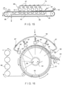
- FIG. 15 depicts an apparatus for continuously producing nonwoven fabrics using a support member in accordance with the present invention.
- the apparatus of FIG. 15 includes a conveyor belt 80 which actually serves as the topographical support member in accordance with the present invention.
- the belt is continuously moved in a counterclockwise direction about a pair of spaced-apart rollers as is well known in the art.
- Disposed above belt 80 is a fluid ejecting manifold 79 connecting a plurality of lines or groups 81 of orifices. Each group has one or more rows of very fine diameter orifices, each about 0.01778 cm in diameter with 30 such orifices per 2.54 cm.
- Water is supplied to the groups 81 of orifices under a predetermined pressure and is ejected from the orifices in the form of very fine, substantially columnar, non-diverging streams or jets of water.
- the manifold is equipped with pressure gauges 88 and control valves 87 for regulating the fluid pressure in each line or group of orifices.
- Disposed beneath each orifice line or group is a suction box 82 for removing excess water, and to keep the area from undue flooding.
- the fiber web 83 to be formed into the nonwoven product is fed to the topographical support member conveyor belt of the present invention.
- Water is sprayed through an appropriate nozzle 84 onto the fibrous web to pre-wet the incoming web 83 and aid in controlling the fibers as they pass under the fluid ejecting manifolds.
- a suction slot 85 is placed beneath this water nozzle to remove excess water. Fibrous web passes under the fluid ejecting manifold in a counter clockwise direction.
- the pressure at which any given group 81 of orifices is operated can be set independently from the pressure at which any of the other groups 81 of orifices is operated.
- the group 81 of orifices nearest spray nozzle 84 is operated at a relatively low pressure, e.g. 7 bar (100 psi). This assists in settling the incoming web onto the surface of the support member.
- the pressures at which the groups 81 of orifices are operated is usually increased. It is not necessary that each succeeding group 81 of orifices be operated at a pressure higher than its neighbor in the clockwise direction. For example, two or more adjacent groups 81 of orifices could be operated at the same pressure, after which the next succeeding group 81 of orifices (in the counterclockwise direction) could be operated at a different pressure. Very typically, the operating pressures at the end of the conveyor belt where the web is removed are higher than the operating pressures where the web is initially fed into the conveyor belt. Though six groups 81 of orifices are shown in FIG.
- this number is not critical, but will depend on the weight of the web, the speed, the pressures used, the number of rows of holes in each group, etc.
- the now formed nonwoven fabric is passed over an additional suction slot 86 to remove excess water.
- the distance from the lower surfaces of the groups 81 of orifices to the upper surface of fibrous web 83 typically ranges from about 12.7 mm (0.5 inch) to about 50.8 mm (2.0 inches); a range of about 19.05 mm (0.75 inch) to about 25.4 mm (1.0 inch) is preferred. It will be apparent that the web cannot be spaced so closely to the manifold that the web contacts the manifold. On the other hand, if the distance between the lower surfaces of the orifices and the upper surface of the web is too great, the fluid streams will lose energy and the process will be less efficient.
- FIG. 16 A preferred apparatus for producing nonwoven fabrics using support members of the present invention is schematically depicted in FIG. 16 .
- the topographical support member is a rotatable drum sleeve 91.
- the drum under the drum sleeve 91 rotates in a counterclockwise direction.
- the outer surface of the drum sleeve 91 comprises the desired topographical support configuration.
- Disposed about a portion of the periphery of the drum is a manifold 89 connecting a plurality of orifice strips 92 for applying water or other fluid to a fibrous web 93 placed on the outside surface of the curved plates.
- Each orifice strip may comprise one or more rows of very fine diameter holes or apertures of the type mentioned earlier herein.
- the apertures are approximately 0.127 mm (0.005 inches) to 0.254 mm (0.01 inches) in nominal diameter, for example. Other sizes, shapes and orientations may obviously be utilized, if suitable for the purpose. Also, there may be, for example, as many as 50 or 60 holes per 2.54 cm or more if desired. Water or other fluid is directed through the rows of orifices.
- the pressure in each orifice group is typically increased from the first group under which the fibrous web passes to the last group. The pressure is controlled by appropriate control valves 97 and is monitored by pressure gauges 98.
- the drum is connected to a sump 94 on which a vacuum may be pulled to aid in removing water and to keep the area from flooding.
- the fibrous web 93 is placed on the upper surface of the topographical support member before the water ejecting manifold 89 as seen in FIG. 16 .
- the fibrous web passes underneath the orifice strips and is formed into a nonwoven product.
- the formed nonwoven is then passed over a section 95 of the apparatus 95 where there are no orifice strips, but vacuum is continued to be applied.
- the fabric after being de-watered is removed from the drum and passed around a series of dry cans 96 to dry the fabric.
- the support members may have a pattern of through voids.
- the through voids may include, among other things, geometrical characteristics that provide enhanced topography and bulk to the nonwoven products or web when produced, for example, on a support member, belt, or sleeve.
- Other advantages of the instant support members include easier web release, improved contamination resistance, and reduced fiber picking.
- Yet another advantage is that it avoids the constraints of and need for a conventional weaving loom since the through voids can be placed in any desired location or pattern.
- the support member may also have a texture on one or both surfaces produced using any of the means known in the art, such as for example, by sanding, graving, embossing, or etching.
- through void is synonymous to the term "through hole” and represents any opening that passes entirely through a support member such as a belt or sleeve.
- a support member as referred to herein includes, but is not limited to, industrial fabrics such as belts or conveyors, and sleeves or cylindrical belts specifically used in nonwoven production.
- fabric and fabric structure is used to describe the preferred embodiments, fabric, belt, conveyor, sleeve, support member, and fabric structure are used interchangeably to describe the structures of the present invention.
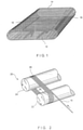
- FIG. 1 is a perspective view of the industrial fabric, belt or sleeve 10 of the present invention.
- the fabric, belt or sleeve 10 has an inner surface 12 and an outer surface 14, and is fashioned by spirally winding a strip of polymeric material 16, for example an industrial strapping material, in a plurality of abutting and mutually adjoined turns.
- the strip of material 16 spirals in a substantially longitudinal direction around the length of the fabric, belt or sleeve 10 by virtue of the helical fashion in which the fabric, belt or sleeve 10 is constructed.
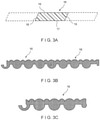
- Apparatus 20 includes a first process roll 22 and a second process roll 24, each of which is rotatable around its longitudinal axis.
- the first process roll 22 and the second process roll 24 are parallel to one another, and are separated by a distance which determines the overall length of the fabric, belt or sleeve 10 to be manufactured thereon, as measured longitudinally therearound.
- a supply reel (not shown in the figures) rotatably mounted about an axis and displaceable parallel to process rolls 22 and 24.
- the supply reel accommodates a reeled supply of the strip of material 16 having a width of 10 mm or more, for example.
- the supply reel is initially positioned at the left-hand end of the first process roll 12, for example, before being continuously displaced to the right or other side at a predetermined speed.
- the beginning of the strip of polymeric strapping material 16 is extended in taut condition from the first process roll 22 toward the second process roll 24, around the second process roll 24, and back to the first process roll 22 forming a first coil of a closed helix 26.
- the beginning of the strip of material 16 is joined to the end of the first coil thereof at point 28.
- adjacent turns of the spirally wound strip of material 16 are joined to one another by mechanical and/or adhesive means.
- subsequent coils of closed helix 26 are produced by rotating first process roll 22 and second process roll 24 in a common direction as indicated by the arrows in FIG. 2 , while feeding the strip of material 16 onto the first process roll 22.
- the strip of material 16 being freshly wound onto the first process roll 22 is continuously joined to that already on the first process roll 22 and the second process roll 24 by, for example, mechanical and/or adhesive or any other suitable means to produce additional coils of closed helix 26.
- the closed helix 26 has a desired width, as measured axially along the first process roll 22 or the second process roll 24. At that point, the strip of material 16 not yet wound onto the first process roll 22 and the second process roll 24 is cut, and the closed helix 26 produced therefrom is removed from the first process roll 22 and the second process roll 24 to provide the fabric, belt or sleeve 10 of the present invention.
- the strips may be wound around the surface of a single roll or mandrel to form the instant fabric, belt or sleeve.
- a roll or mandrel of appropriate size may be selected based on the desired dimension of the fabric, belt or sleeve to be produced.
- the present method for producing fabric, belt or sleeve 10 is quite versatile and adaptable to the production of nonwoven and/or industrial fabrics or belt or sleeves of a variety of longitudinal and transverse dimensions. That is to say, the manufacturer, by practicing the present invention, need no longer produce a woven fabric of appropriate length and width for a given nonwoven production machine. Rather, the manufacturer need only separate the first process roll 22 and the second process roll 24 by the appropriate distance, to determine the approximate length of the fabric, belt or sleeve 10, and wind the strip of material 16 onto the first process roll 22 and the second process roll 24 until the closed helix 26 has reached the approximate desired width.
- the fabric, belt or sleeve 10 is produced by spirally winding a strip of polymeric strapping material 16, and is not a woven fabric, the outer surface 12 of the fabric, belt or sleeve 10 can be smooth and continuous, and lacks the knuckles which prevent the surfaces of a woven fabric from being perfectly smooth.
- the fabrics, belts, or sleeves of the present invention may, however, have geometrical characteristics that provide enhanced topography and bulk to the nonwoven product produced thereon.
- Other advantages of the instant support members include easier web release, improved contamination resistance, and reduced fiber picking.
- Yet another advantage is that it avoids the constraints of and need for a conventional weaving loom since the through voids can be placed in any desired location or pattern.
- the fabric, belt or sleeve may also have a texture on one or both surfaces produced using any of the means known in the art, such as for example, by sanding, graving, embossing or etching.
- the fabric, belt or sleeve may be smooth on one or both surfaces.
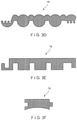
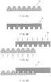
- FIGS. 3(a) through 3(i) are cross-sectional views, taken in a widthwise direction, of several embodiments of the strip of material used to produce the present fabric, belt or sleeve.
- Each embodiment includes upper and lower surfaces which may be flat (planar) and parallel to one another, or may have a certain profile intended to suit a particular application.
- material strip 16 has an upper surface 15, a lower surface 17, a first planar side 18 and a second planar side 19, according to one embodiment of the invention.
- the upper surface 15 and the lower surface 17 may be flat (planar) and parallel to one another, and the first planar side 18 and the second planar side 19 may be slanted in parallel directions, so that the first planar side 18 of each spirally wound strip of material 16 abuts closely against the second planar side 19 of the immediately preceding turn thereof.
- Each turn of the strip of material 16 is joined to its adjacent turns by joining their respective first and second planar sides 18, 19 to one another by an adhesive, for example, which may be a heat-activated, room-temperature-cured (RTC) or hot-melt adhesive, for example, or any other suitable means.
- RTC room-temperature-cured
- material strip 16 may have a cross-sectional structure that enables a mechanical interlock for joining adjacent strips of material 16 in the spirally formed fabric, belt or sleeve. Adjacent strips of material 16 can be the same or different in size and/or profile, but each has a locking position, as shown in FIG. 3(b) .
- Other examples of mechanical interlock structures are shown in FIGS. 3(c) through 3(g) where the cross section of individual strips of material 16 is illustrated. In each case, one side of the strip of material 16 may be designed to mechanically interlock or connect with the other side of the adjacent strip of material 16. For example, referring to the embodiment shown in FIG.
- the strip of material 16 may have an upper surface 42, a lower surface 44, a tongue 46 on one side and a corresponding groove 48 on the other side.
- the tongue 46 may have dimensions corresponding to those of the groove 48, so that the tongue 46 on each spirally wound turn of strip 16 fits into the groove 48 of the immediately preceding turn thereof.
- Each turn of the strip of material 16 is joined to its adjacent turns by securing tongues 46 in the grooves 48.
- the upper surface 42 and the lower surface 44 may be flat (planar) and parallel to one another, or non-planar and non-parallel depending on the application, or even may be convexly or concavely rounded in the widthwise direction thereof, as shown in FIG. 3(f) .
- either sides of the strip may be cylindrically convex or concave shaped with the same radius of curvature.
- FIG. 3(h) shows another embodiment of the present invention.
- FIG. 3(i) One such structure, according to one exemplary embodiment of the invention is shown in FIG. 3(i) .
- the material strip may not require a right and left side that mate or join together.
- the cross section of strip of material 16 may have interlocking grooves on its upper surface or top side, or material strip 16 may have interlocking grooves on its lower surface or bottom side, as shown in FIG. 4(b) .
- FIG. 4(c) shows the material strips of FIGS. 4(a) and 4(b) positioned for interlocking.
- the arrows in FIG. 4(c) indicate, for example, the direction that each of the material strips 16 would have to be moved in order to engage the grooves and interlock the two strips.
- FIG. 4(d) shows the two material strips 16 after they have been interlocked or joined together. Although only two of the mating material strips are shown in the exemplary embodiments, it should be noted that the final fabric, belt or sleeve is formed of several of the material strips interlocked together. Clearly, if one interlocks the material strips in a spiral winding process, one can form a sheet of material in the form of an endless loop.
- the strength of the interlocks can be improved by, for example, thermal bonding, especially by a technique known as selective bonding as exemplified by a commercial process known as 'Clearweld' (See www.clearweld.com).
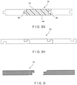
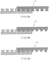
- FIG. 5(a) shows a cross-sectional view of a material strip 16 that has grooves both on the top side and bottom side thereof.
- FIG. 5(b) shows how two material strips 16 having the cross-sectional shape shown in FIG. 5(a) can be interlocked. The interlocked structure results in grooves on the top and bottom surface of the end product.
- FIG. 5(c) shows the interlocking of the two material strips 16 shown in FIG. 5(a) and FIG. 4(b) .
- FIG. 6(a) illustrates the features of knoblike interlocks in individual ribbon-like material strips 16.
- FIG. 6(b) illustrates the features of knoblike interlocks in individual ribbon-like material strips 16 of opposite configuration that are designed to interlock with the structure shown in FIG. 6(a).
- FIG. 6(c) shows the individual ribbon-like material strips of FIGS.
- FIG. 6(a) and 6(b) positioned for interlocking. It is to be noted here that the staggered position of the top and bottom ribbons is in order to accommodate another material strip 16 of opposite configuration.
- FIG. 6(d) illustrates these same strips after they have been pressed together to form an interlocked structure. Several ribbon-like material strips like these may be interlocked together to form the final fabric, belt or sleeve.
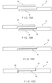
- FIG. 7(a) Another exemplary embodiment is a fabric, belt or sleeve formed from material strips 16 that have grooves on both the top and bottom sides thereof, for example, as shown in FIG. 7(a) .
- These two ribbon-like material strips 16 are designed to be joined together to form a positive interlock, as shown in FIG. 7(b) .
- the top and bottom surfaces both retain grooves in their respective surfaces.
- FIGS. 7(a) and 7(b) it may be apparent to one of ordinary skill in the art to combine three strips to make a three-layered structure, or if just two strips are used, the groove profile of the grooves in the top strip may be different on top versus bottom sides.
- the groove profile of the grooves in the bottom strip may be the same or different on either sides.
- the belt may have two or more layers where the strips may be formed such that the two or more layers mechanically interlock. Each layer may be spirally wound in an opposite direction or angled in the MD to provide additional strength.
- FIG. 7(c) shows an interlocked structure that results in a grooved bottom surface and a flat top surface
- FIG. 7(d) shows an interlocked structure that results in a flat bottom surface and a grooved top surface, for example.
- the mechanical interlock thus formed between adjacent strips of material as described in the above embodiments increases the ease with which a spiral wound base fabric or structure can be made, because without such a lock, it is possible for adjacent strips of material to wander and separate during the process of making the spirally wound fabric.
- By mechanically interlocking adjacent spirals one may prevent wandering and separation between adjacent spirals. Additionally, one may not need to depend solely on the strength of the mechanical lock for joining strength as one may also form thermal welds in the mechanically locked zones of the fabric.
- this can be accomplished by placing a near infrared or infrared or laser absorbing dye prior to locking the male/female components together followed by exposing the mechanical lock to a near infrared or infrared energy or laser source that causes thermal welding of the mechanical lock without melting material external to the zone of the mechanical lock.
- the strip of material described in the above embodiments may be extruded from any polymeric resin material known to those of ordinary skill in the art, such as for example, polyester, polyamide, polyurethane, polypropylene, polyether ether ketone resins, etc.
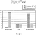
- Industrial strapping is attractive as a base material, given that it is uniaxally oriented, i.e., it has at least twice the tensile modulus of a biaxially oriented material (film) and up to ten times the modulus of an extruded material (molded). That is to say, the structure resulting from a uniaxially oriented material requires less than half the thickness of biaxially oriented material (film) and less than one-tenth the thickness of an extruded material (molded).
- the force (or load) is kept constant along with the width and strain in this illustration.
- the equation shows that the required thickness is inversely proportional to the modulus of the material.
- This equation is representative of the problem of designing nonwoven production machine clothing for dimensional stability, i.e., the load is known, the maximum strain is known and the width of the machine is fixed. The result is shown in terms of the final thickness of the part required depending upon the modulus of the material employed.
- uniaxial materials such as strappings or ribbons have a significant advantage over films and molded polymers as shown by FIG. 9 .
- the instant support members, belts or sleeves are not limited to uniaxial or biaxial orientation of the strapping, in that either or both orientations may be used in the practice of the instant invention.
- the strip of material or strapping material described in the above embodiments includes a reinforcing material to improve the mechanical strength of the overall structure.
- the reinforcing material may be fibers, yarns, monofilaments or multifilament yarns oriented in the MD of the fabric, sleeve or belt, along the length of the strapping material.
- the reinforcing material may be included through an extrusion or pultrusion process where the fibers or yarns may be extruded or pultruded along with the material forming the strip of material or strapping material. They may be fully embedded within the material of the strapping or they may be partially embedded onto one or both surfaces of the strapping material, or both.
- Reinforcing fibers or yarns may be formed of a high-modulus material, such as for example, aramids, including but not limited to Kevlar ® and Nomex ® , and may provide extra strength, tensile modulus, tear and/or crack resistance, resistance to abrasion and/or chemical degradation to the strip of material or strapping material.
- the reinforcing fibers or yarns may be made from thermoplastic and/or thermosetting polymers.
- suitable fiber materials include glass, carbon, polyester, and polyethylene.
- the melting temperature of said reinforcing fibers or yarns is higher than the melting temperature of said strip of material or strapping material. Strapping is usually supplied in continuous lengths with the product having a rectangular cross section.
- Typical cross-sectional dimensions of a strapping material that may be used in the present invention are, for example, 0.30mm (or more) thickness and 10mm (or more) width. While strapping can be spirally wound, the adjacent wraps of strapping that do not have any means of interlocking to be held together may need to welded or joined in some manner. In such cases, laser welding or ultrasonic welding may be used in to fix or weld the adjacent ribbons or material strips together so as to improve cross-machine direction (“CD”) properties, such as strength, and reducing the risk of separation of neighboring material strips.
- CD cross-machine direction
- non-oriented strips may have a typical MD modulus of about 3GPa and strength of about 50MPa.
- a biaxially oriented strip may have a MD modulus of about 4.7GPa and strength of about 170MPa.
- modifying the processing of a uniaxial strip such that the MD modulus may be between 6-10GPa and strength may be equal to or greater than 250MPa, may result in a strip with CD strength approaching, approximately, 100MPa.
- the material may be less brittle, i.e. it may not crack when repeatedly flexed, and may process better when joining the strips together.
- the bond between the strips may also resist separation during the intended use on the production machine.
- One method to hold together the adjacent strips is to ultrasonically weld adjacent strips edge to edge while simultaneously providing a sideways pressure to keep the edges in contact with each other.
- one part of the welding device can hold one strip, preferably the strip that has already been wound into a spiral, down against a supporting roll while another part of the device pushes the other strip, preferably the strip being unwound, up against the strip being held down.
- This edge to edge welding is illustrated in FIG. 11(a) , for example.
- ultrasonic gap welding results in a particularly strong bond.
- ultrasonic welding in either a time mode or energy mode which is also known as conventional ultrasonic welding, results in a bond that can be described as brittle. Therefore, it may be concluded that a bond formed via ultrasonic gap welding is preferred versus conventional ultrasonic welding.
- FIGS. 10(a) -10(d) Another exemplary method to hold together adjacent strips, according to one embodiment of the invention, is to apply an adhesive 30 to ends 34, 36 of adjacent strips 16, 16, and joining them is shown in FIGS. 10(a) -10(d) . It is to be noted that a filler material 32, may be used to fill gaps or portions where the strips do not contact each other.
- FIG. 11(b) Another method to hold together adjacent strips of material or functional strips, according to one embodiment of the invention, is to use a "welding strip" comprised of the same basic material as the strip of material.
- this welding strip is shown in FIG. 11(b) as a thin material appearing above and below the strips of material.
- the welding strip provides a material for the strips of material to be welded such that the assembled structure does not depend upon the edge to edge welding depicted in FIG. 11(a) .
- edge to edge welding may result; however, it is neither required nor preferred.
- a "sandwich" or laminate type of structure may be formed with the horizontal surface of the strip of material being welded to the horizontal surface of the welding strip, as shown in FIG. 11(b) .
- the welding strip does not have to be located both above and below the strips of material, in that the welding strip may be located either just above or just below the strips of material.
- the welding strip may also be the central part of the sandwiched structure with the strip of material being above and/or below the welding strip.
- the welding strip is shown as being thinner than the strip of material and as being the same width as the strip of material merely for exemplary purposes.
- the welding strip may well be narrower or broader than the strip of material, and may be of the same thickness or even thicker than the strip of material.
- the welding strip may also be another piece of strip of material rather than being a special material made solely for the purpose of the welding strip.
- the welding strip may also have adhesive applied to one of its surfaces to assist in holding the welding strip in place for the welding operation. However, if such an adhesive is used, it is preferred that the adhesive be partially applied to the welding strip versus the entire surface, because partial application may promote a strong weld between like materials (polyester to polyester, for example) of the strip of material and the welding strip upon ultrasonic or laser welding.
- the welding strip is made from an extruded polymer with no orientation, then it is preferred that the welding strip be much thinner than the strip of material, because a non-oriented extruded welding strip is less capable of maintaining the dimensional stability of the final structure as illustrated earlier in this disclosure.
- the welding strip is made from an oriented polymer, it is preferred that the welding strip in combination with the strip of material be as thin as possible.
- the welding strip may be another piece of strip of material. However, if this is the case, it is preferred that the thickness of the individual materials be selected such that the total thickness of the sandwich or laminate can be minimized.
- the welding strip may be coated with an adhesive that is used to hold the structure together for further processing.
- the welding strip with adhesive may be used, for example, to create a structure that goes directly to a perforation step, which could be laser drilling without any ultrasonic bonding such that the laser drilling or laser perforation produces spot welds that can hold the sandwich structure together.
- Another method to hold together adjacent strips of material is to weld the adjacent strips using a laser welding technique.
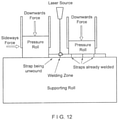
- FIG. 14 illustrates an exemplary apparatus 320 that may be used in the laser welding process, according to one aspect of the invention.
- fabric, belt or sleeve 322 as shown in FIG. 14 should be understood to be a relatively short portion of the entire length of the final fabric, belt or sleeve.
- the fabric, belt or sleeve 322 may be endless, it may most practically be mounted about a pair of rolls, not illustrated in the figure, but known to those of ordinary skill in the art.
- apparatus 320 may be disposed on one of the two surfaces, most conveniently the top surface, of the fabric 322 between the two rolls.
- fabric 322 may preferably be placed under an appropriate degree of tension during the process.
- fabric 322 may be supported from below by a horizontal support member as it moves through apparatus 320.
- FIG. 14 where fabric 322 is indicated as moving in an upward direction through the apparatus 320 as the method of the present invention is being practiced.
- the laser heads that are used in the welding process may traverse across the fabric in a CD or widthwise "X" direction while the fabric may move in the MD or "Y” direction. It may also be possible to setup a system where the fabric is moved in three-dimensions relative to a mechanically fixed laser welding head.
- laser welding can be accomplished at speeds in the range of 100 meters per minute while ultrasonic welding has a top end speed of about 10 meters per minute.
- a light absorptive dye or ink absorber to the edges of the strips may also assist in concentrating the thermal effect of the laser.
- Absorbers could be black ink or near IR dyes that are not visible to the human eye, such as for example those utilized by "Clearweld.” (See www.clearweld.com)
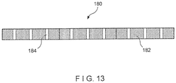
- holes or perforations allowing fluids (air and/or water) to pass from one side of the fabric to the other side of the fabric can be provided by means such as laser drilling. It should be noted that these through holes or perforations that allow fluid to pass from one side of the fabric to the other can be made either before or after the spiral winding and joining process. Such holes or perforations can be made via laser drilling or any other suitable hole/perforation making process, and can be of any size, shape, form and/or pattern, depending on the intended use. An exemplary embodiment is shown in FIG.
- strips of material 82 are provided along their entire lengths with a plurality of holes 84 for the passage of air and/or water.
- the inventive fabric may be used as a process belt or sleeve used in airlaid, melt blowing, spunbonding, or hydroentangling processes.
- the inventive fabric, belt or sleeve may include one or more additional layers on top of or under the substrate formed using the strips of material, merely to provide functionality, and not reinforcement.
- a MD yarn array may be laminated to the backside of the belt or sleeve to create void spaces.
- the one or more layers may be provided in between two layers of strapping.
- the additional layers used may be any of woven or nonwoven materials, MD or CD yarn arrays, spirally wound strips of woven material that have a width less than the width of the fabric, fibrous webs, films, or a combination thereof, and may be attached to the substrate using any suitable technique known to one of ordinary skill in the art. Needle punching, thermal bonding and chemical bonding are but few examples.
- the inventive fabric, belt or sleeve may also have a coating on either side for functionality.
- the texture on the fabric, belt or sleeve of the present invention may be produced before or after applying the functional coating. As aforementioned, the texture on the fabric, belt or sleeve can be produced using any of the means known in the art, such as for example, sanding, graving, embossing or etching.
Landscapes
- Nonwoven Fabrics (AREA)
- Shaping Of Tube Ends By Bending Or Straightening (AREA)
- Treatment Of Fiber Materials (AREA)
- Laminated Bodies (AREA)
- Making Paper Articles (AREA)
- Lining Or Joining Of Plastics Or The Like (AREA)
- Paper (AREA)
Claims (32)
- Endlosband oder Hülse zur Verwendung bei der Vliesherstellung, wobei das Band oder die Hülse (10) umfasst:einen oder mehrere spiralförmig gewickelte Streifen von Polymermaterial (16), wobei der eine oder mehrere Streifen von Polymermaterial ein technisches Umreifungs- oder Bandmaterial sind,wobei das Umreifungs- oder Bandmaterial uniaxial ausgerichtet ist und zumindest das Zweifache des Zugmoduls eines biaxial ausgerichteten Materials und bis zum Zehnfachen des Moduls eines extrudierten Materials aufweist,dadurch gekennzeichnet, dass das technische Umreifungs- oder Bandmaterial ein Verstärkungsmaterial enthält, das in der MD des Bandes oder der Hülse, ausgewählt aus der Gruppe bestehend aus Fasern, Garnen, Monofilamenten und Multifilamentgarnen, ausgerichtet ist,wobei das Verstärkungsmaterial aus einem Material hergestellt ist, das aus der aus Aramiden, thermoplastischen Polymeren, wärmehärtbaren Polymeren, Glas und Kohlenstoff bestehenden Gruppe ausgewählt ist,und wobei die Schmelztemperatur des Umreifungs- oder Bandmaterials niedriger als die Schmelztemperatur des Verstärkungsmaterials ist.
- Band oder Hülse nach Anspruch 1, wobei das Band oder die Hülse für die Verwendung in einem Airlaid-, Schmelzblas-, Spun-Bonding- oder Wasserstrahlverfestigungsverfahren geeignet ist.
- Band oder Hülse nach Anspruch 1, wobei das technische Umreifungs- oder Bandmaterial eine Dicke von 0,30 mm oder mehr und eine Breite von 10 mm oder mehr aufweist.
- Band oder Hülse nach Anspruch 1, wobei das Band oder die Hülse für Luft und/oder Wasser durchlässig oder undurchlässig ist.
- Band oder Hülse nach Anspruch 4, wobei das Band oder die Hülse für Luft und/oder Wasser durchlässig ist, und durchgehende Hohlräume oder Löcher in dem Band oder der Hülse unter Anwendung eines mechanischen oder thermischen Mittels erzeugt sind.
- Band oder Hülse nach Anspruch 5, wobei die durchgehenden Hohlräume oder Löcher in einer vorgegebenen Größe, Form oder Ausrichtung gebildet sind.
- Band oder Hülse nach Anspruch 6, wobei die durchgehenden Hohlräume oder Löcher einen Nenndurchmesser im Bereich von 0,0127 cm (0,005 Zoll) bis 0,0254 cm (0.01 Zoll) oder mehr aufweisen.
- Band oder Hülse nach Anspruch 1, zusätzlich umfassend eine oder mehrere Schichten von Gewebe- oder Vliesmaterialien, MD- oder CD-Garnanordnungen, spiralförmig gewickelten Streifen eines Gewebematerials mit einer Breite, die kleiner als die Breite des Bandes oder der Hülse ist.
- Band oder Hülse nach Anspruch 1, wobei angrenzende Streifen von Polymermaterial mechanisch miteinander verbunden sind.
- Band oder Hülse nach Anspruch 1, wobei das Band oder die Hülse eine Textur auf einer oder beiden Flächen aufweist.
- Band oder Hülse nach Anspruch 10, wobei die Textur durch Schleifen, Gravieren, Prägen oder Ätzen vorgesehen ist.
- Band oder Hülse nach Anspruch 1, wobei das Band oder die Hülse auf einer oder beiden Flächen glatt ist.
- Band oder Hülse nach Anspruch 1, wobei das Band oder die Hülse zumindest zwei Schichten von Umreifungsmaterialien umfasst, die in entgegengesetzten Richtungen zueinander oder entgegengesetzt zur MD spiralförmig gewickelt sind.
- Band oder Hülse nach Anspruch 1, zusätzlich umfassend eine funktionelle Beschichtung auf einer oder beiden Seiten des Bandes oder der Hülse.
- Band oder Hülse nach Anspruch 8, wobei die eine oder mehrere Schichten auf einer oder beiden Seiten des Bandes oder der Hülse oder zwischen zwei Umreifungsschichten vorgesehen sind.
- Band oder Hülse nach Anspruch 14, wobei die funktionelle Beschichtung eine Textur auf ihrer oberen Fläche aufweist.
- Verfahren zum Bilden eines Endlosbandes oder einer Hülse (1) zur Verwendung bei der Vliesherstellung, welches Verfahren die folgenden Schritte umfasst:spiralförmiges Wickeln von einem oder mehreren Streifen von Polymermaterial (16) um eine Vielzahl von Rollen, wobei der eine oder mehrere Streifen von Polymermaterial ein technisches Umreifungs- oder Bandmaterial sind; und Verbinden von Kanten benachbarter Materialstreifen;wobei das Umreifungs- oder Bandmaterial uniaxial ausgerichtet ist und zumindest das Zweifache des Zugmoduls eines biaxial ausgerichteten Materials und bis zum Zehnfachen des Moduls eines extrudierten Materials aufweist;und Verstärken des technischen Umstreifungs- oder Bandmaterials in der MD des Bandes oder der Hülse mit Fasern, Garnen, Monofilamenten oder Multifilamentgarnen,wobei das Verstärkungsmaterial aus einem Material hergestellt ist, das aus der aus Aramiden, thermoplastischen Polymeren, wärmehärtbaren Polymeren, Glas und Kohlenstoff bestehenden Gruppe ausgewählt ist,und wobei die Schmelztemperatur des Umreifungs- oder Bandmaterials niedriger als die Schmelztemperatur des Verstärkungsmaterials ist.
- Verfahren nach Anspruch 17, wobei ein oder mehrere Umreifungs- oder Bandmaterialien durch Laser-, Infrarot- oder Ultraschallschweißen zusammengefügt werden.
- Verfahren nach Anspruch 17, wobei das technische Umreifungs- oder Bandmaterial eine Dicke von 0,30 mm oder mehr und eine Breite von 10 mm oder mehr aufweist.
- Verfahren nach Anspruch 17, wobei das Band oder die Hülse für Luft und/oder Wasser durchlässig oder undurchlässig gemacht wird.
- Verfahren nach Anspruch 20, wobei das Band oder die Hülse durch das Erzeugen von durchgehenden Hohlräumen oder Löchern in dem Band oder der Hülse unter Anwendung eines mechanischen oder thermischen Mittels für Luft und/oder Wasser durchlässig gemacht wird.
- Verfahren nach Anspruch 21, wobei die durchgehenden Hohlräume oder Löcher in einer vorgegebenen Größe, Form oder Ausrichtung gebildet werden.
- Verfahren nach Anspruch 22, wobei die durchgehenden Hohlräume oder Löcher einen Nenndurchmesser im Bereich von 0,0127 cm (0,005 Zoll) bis 0,0254 cm (0.01 Zoll) oder mehr aufweisen.
- Verfahren nach Anspruch 17, ferner umfassend den folgenden Schritt:Aufbringen von einer oder mehreren Schichten von Gewebe- oder Vliesmaterialien, MD- oder CD-Garnanordnungen, spiralförmig gewickelten Streifen eines Gewebematerials mit einer Breite, die kleiner als die Breite des Bandes oder der Hülse ist, auf eine obere und/oder untere Fläche des Bandes oder der Hülse.
- Verfahren Anspruch 17, wobei angrenzende Streifen von Polymermaterial mechanisch miteinander verbunden werden.
- Verfahren nach Anspruch 17, wobei das Band oder die Hülse mit einer Textur auf einer oder beiden Flächen versehen wird.
- Verfahren nach Anspruch 26, wobei die Textur durch Schleifen, Gravieren, Prägen oder Ätzen vorgesehen wird.
- Verfahren nach Anspruch 17, wobei das Band oder die Hülse auf einer oder beiden Flächen glatt ist.
- Verfahren nach Anspruch 17, wobei das Band oder die Hülse zumindest zwei Schichten von Umreifungsmaterialien umfasst, die in entgegengesetzten Richtungen zueinander oder entgegengesetzt zur MD spiralförmig gewickelt sind.
- Verfahren nach Anspruch 17, zusätzlich umfassend den Schritt des Beschichtens auf einer oder beiden Seiten des Bandes oder der Hülse mit einer funktionellen Beschichtung.
- Verfahren nach Anspruch 24, wobei die eine oder mehrere Schichten auf einer oder beiden Seiten des Bandes oder der Hülse oder zwischen zwei Umreifungsschichten vorgesehen werden.
- Verfahren nach Anspruch 30, zusätzlich umfassend den Schritt des Bereitstellens einer Textur für die funktionelle Beschichtung.
Priority Applications (1)
| Application Number | Priority Date | Filing Date | Title |
|---|---|---|---|
| PL13724690.6T PL2847379T5 (pl) | 2012-05-11 | 2013-05-09 | Tkanina przemysłowa zawierająca spiralnie nawinięte paski materiału ze wzmocnieniem |
Applications Claiming Priority (2)
| Application Number | Priority Date | Filing Date | Title |
|---|---|---|---|
| US13/469,966 US8728280B2 (en) | 2008-12-12 | 2012-05-11 | Industrial fabric including spirally wound material strips with reinforcement |
| PCT/US2013/040364 WO2013170042A1 (en) | 2012-05-11 | 2013-05-09 | Industrial fabric including spirally wound material strips with reinforcement |
Publications (3)
| Publication Number | Publication Date |
|---|---|
| EP2847379A1 EP2847379A1 (de) | 2015-03-18 |
| EP2847379B1 EP2847379B1 (de) | 2018-07-25 |
| EP2847379B2 true EP2847379B2 (de) | 2022-03-02 |
Family
ID=48483230
Family Applications (1)
| Application Number | Title | Priority Date | Filing Date |
|---|---|---|---|
| EP13724690.6A Active EP2847379B2 (de) | 2012-05-11 | 2013-05-09 | Technisches gewebe mit spiralförmig gewickelten materialbahnen mit verstärkung |
Country Status (13)
| Country | Link |
|---|---|
| EP (1) | EP2847379B2 (de) |
| JP (1) | JP6502250B2 (de) |
| KR (1) | KR20150020193A (de) |
| CN (1) | CN104395524A (de) |
| BR (1) | BR112014027988B1 (de) |
| CA (1) | CA2872784A1 (de) |
| ES (1) | ES2690377T5 (de) |
| IN (1) | IN2014MN02267A (de) |
| MX (1) | MX362291B (de) |
| PL (1) | PL2847379T5 (de) |
| RU (1) | RU2633270C2 (de) |
| TW (1) | TWI626346B (de) |
| WO (1) | WO2013170042A1 (de) |
Families Citing this family (1)
| Publication number | Priority date | Publication date | Assignee | Title |
|---|---|---|---|---|
| US9938666B2 (en) * | 2015-05-01 | 2018-04-10 | The Procter & Gamble Company | Unitary deflection member for making fibrous structures having increased surface area and process for making same |
Family Cites Families (23)
| Publication number | Priority date | Publication date | Assignee | Title |
|---|---|---|---|---|
| CA708758A (en) | 1965-05-04 | Plate And Suter | Tubular sieve | |
| US3214819A (en) | 1961-01-10 | 1965-11-02 | Method of forming hydrauligally loomed fibrous material | |
| US3508308A (en) | 1962-07-06 | 1970-04-28 | Du Pont | Jet-treatment process for producing nonpatterned and line-entangled nonwoven fabrics |
| US3475264A (en) | 1964-07-21 | 1969-10-28 | Chase Donaldson | Reinforced plastic strapping laminate |
| US3485706A (en) | 1968-01-18 | 1969-12-23 | Du Pont | Textile-like patterned nonwoven fabrics and their production |
| DE2538691A1 (de) * | 1975-08-30 | 1977-03-03 | Continental Gummi Werke Ag | Verfahren zum herstellen von foerdergurten |
| US4776905A (en) | 1986-06-06 | 1988-10-11 | Signode Corporation | Method and apparatus for producing a welded joint in thermoplastic strap |
| US5098764A (en) | 1990-03-12 | 1992-03-24 | Chicopee | Non-woven fabric and method and apparatus for making the same |
| US5244711A (en) | 1990-03-12 | 1993-09-14 | Mcneil-Ppc, Inc. | Apertured non-woven fabric |
| SE468602B (sv) | 1990-12-17 | 1993-02-15 | Albany Int Corp | Pressfilt samt saett att framstaella densamma |
| FR2730246B1 (fr) | 1995-02-03 | 1997-03-21 | Icbt Perfojet Sa | Procede pour la fabrication d'une nappe textile non tissee par jets d'eau sous pression, et installation pour la mise en oeuvre de ce procede |
| FR2734285B1 (fr) | 1995-05-17 | 1997-06-13 | Icbt Perfojet Sa | Procede pour la fabrication d'une nappe textile non tissee par jets d'eau sous pression, et installation pour la mise en oeuvre de ce procede |
| US6124015A (en) * | 1996-04-18 | 2000-09-26 | Jwi Ltd. | Multi-ply industrial fabric having integral jointing structures |
| DE29923825U1 (de) | 1999-11-24 | 2001-04-05 | Schäfer KG Gummiwalzenfabrik, 71272 Renningen | Preßmantel, Preßband oder Walzenbeschichtung |
| US6630223B2 (en) | 2001-01-26 | 2003-10-07 | Albany International Corp. | Spirally wound shaped yarns for paper machine clothing and industrial belts |
| JP4627137B2 (ja) | 2003-03-19 | 2011-02-09 | イチカワ株式会社 | 湿紙搬送用ベルト |
| GB0325463D0 (en) | 2003-10-31 | 2003-12-03 | Voith Fabrics Patent Gmbh | Three dimensional tomographic fabric assembly |
| US8058188B2 (en) | 2005-04-13 | 2011-11-15 | Albany International Corp | Thermally sprayed protective coating for industrial and engineered fabrics |
| DE102006023935A1 (de) | 2006-02-07 | 2007-11-29 | Tesa Ag | Durch Filamente verstärktes Klebeband |
| WO2010030570A1 (en) * | 2008-09-11 | 2010-03-18 | Albany International Corp. | Industrial fabric, and method of making thereof |
| CN106995981A (zh) * | 2008-12-12 | 2017-08-01 | 阿尔巴尼国际公司 | 包括螺旋缠绕材料条带的工业织物 |
| WO2010088283A1 (en) * | 2009-01-28 | 2010-08-05 | Albany International Corp. | Papermaking fabric for producing tissue and towel products, and method of making thereof |
| DE102009037834A1 (de) | 2009-08-18 | 2011-03-03 | Silu Verwaltung Ag | Klebeband mit einer reißbaren Trennfolie |
-
2013
- 2013-05-09 KR KR20147034749A patent/KR20150020193A/ko active Search and Examination
- 2013-05-09 MX MX2014013732A patent/MX362291B/es active IP Right Grant
- 2013-05-09 CN CN201380033662.2A patent/CN104395524A/zh active Pending
- 2013-05-09 ES ES13724690T patent/ES2690377T5/es active Active
- 2013-05-09 EP EP13724690.6A patent/EP2847379B2/de active Active
- 2013-05-09 IN IN2267MUN2014 patent/IN2014MN02267A/en unknown
- 2013-05-09 CA CA2872784A patent/CA2872784A1/en not_active Abandoned
- 2013-05-09 WO PCT/US2013/040364 patent/WO2013170042A1/en active Application Filing
- 2013-05-09 RU RU2014144738A patent/RU2633270C2/ru active
- 2013-05-09 PL PL13724690.6T patent/PL2847379T5/pl unknown
- 2013-05-09 JP JP2015511707A patent/JP6502250B2/ja active Active
- 2013-05-09 BR BR112014027988-8A patent/BR112014027988B1/pt active IP Right Grant
- 2013-05-10 TW TW102116672A patent/TWI626346B/zh active
Also Published As
| Publication number | Publication date |
|---|---|
| RU2014144738A (ru) | 2016-07-10 |
| EP2847379B1 (de) | 2018-07-25 |
| PL2847379T5 (pl) | 2022-07-25 |
| CA2872784A1 (en) | 2013-11-14 |
| TW201400663A (zh) | 2014-01-01 |
| MX2014013732A (es) | 2015-09-21 |
| PL2847379T3 (pl) | 2018-12-31 |
| TWI626346B (zh) | 2018-06-11 |
| RU2633270C2 (ru) | 2017-10-11 |
| BR112014027988B1 (pt) | 2021-10-05 |
| KR20150020193A (ko) | 2015-02-25 |
| EP2847379A1 (de) | 2015-03-18 |
| ES2690377T5 (es) | 2022-05-31 |
| JP6502250B2 (ja) | 2019-04-17 |
| MX362291B (es) | 2019-01-09 |
| WO2013170042A1 (en) | 2013-11-14 |
| JP2015516034A (ja) | 2015-06-04 |
| CN104395524A (zh) | 2015-03-04 |
| IN2014MN02267A (de) | 2015-07-24 |
| BR112014027988A2 (pt) | 2017-06-27 |
| ES2690377T3 (es) | 2018-11-20 |
Similar Documents
| Publication | Publication Date | Title |
|---|---|---|
| EP2376690B1 (de) | Technisches gewebe und verfahren zum herstellen | |
| US8728280B2 (en) | Industrial fabric including spirally wound material strips with reinforcement | |
| EP2847380B1 (de) | Technisches gewebe mit spiralförmig gewickelten materialbahnen mit verstärkung | |
| EP2847379B2 (de) | Technisches gewebe mit spiralförmig gewickelten materialbahnen mit verstärkung |
Legal Events
| Date | Code | Title | Description |
|---|---|---|---|
| PUAI | Public reference made under article 153(3) epc to a published international application that has entered the european phase |
Free format text: ORIGINAL CODE: 0009012 |
|
| 17P | Request for examination filed |
Effective date: 20141121 |
|
| AK | Designated contracting states |
Kind code of ref document: A1 Designated state(s): AL AT BE BG CH CY CZ DE DK EE ES FI FR GB GR HR HU IE IS IT LI LT LU LV MC MK MT NL NO PL PT RO RS SE SI SK SM TR |
|
| AX | Request for extension of the european patent |
Extension state: BA ME |
|
| DAX | Request for extension of the european patent (deleted) | ||
| 17Q | First examination report despatched |
Effective date: 20160609 |
|
| STAA | Information on the status of an ep patent application or granted ep patent |
Free format text: STATUS: EXAMINATION IS IN PROGRESS |
|
| GRAP | Despatch of communication of intention to grant a patent |
Free format text: ORIGINAL CODE: EPIDOSNIGR1 |
|
| STAA | Information on the status of an ep patent application or granted ep patent |
Free format text: STATUS: GRANT OF PATENT IS INTENDED |
|
| INTG | Intention to grant announced |
Effective date: 20180223 |
|
| GRAS | Grant fee paid |
Free format text: ORIGINAL CODE: EPIDOSNIGR3 |
|
| GRAA | (expected) grant |
Free format text: ORIGINAL CODE: 0009210 |
|
| STAA | Information on the status of an ep patent application or granted ep patent |
Free format text: STATUS: THE PATENT HAS BEEN GRANTED |
|
| AK | Designated contracting states |
Kind code of ref document: B1 Designated state(s): AL AT BE BG CH CY CZ DE DK EE ES FI FR GB GR HR HU IE IS IT LI LT LU LV MC MK MT NL NO PL PT RO RS SE SI SK SM TR |
|
| REG | Reference to a national code |
Ref country code: GB Ref legal event code: FG4D |
|
| REG | Reference to a national code |
Ref country code: CH Ref legal event code: EP |
|
| REG | Reference to a national code |
Ref country code: AT Ref legal event code: REF Ref document number: 1021889 Country of ref document: AT Kind code of ref document: T Effective date: 20180815 |
|
| REG | Reference to a national code |
Ref country code: DE Ref legal event code: R096 Ref document number: 602013040801 Country of ref document: DE |
|
| REG | Reference to a national code |
Ref country code: IE Ref legal event code: FG4D |
|
| REG | Reference to a national code |
Ref country code: CH Ref legal event code: NV Representative=s name: ROSENICH PAUL; KUENSCH JOACHIM PATENTBUERO PAU, LI |
|
| REG | Reference to a national code |
Ref country code: NL Ref legal event code: FP |
|
| REG | Reference to a national code |
Ref country code: SE Ref legal event code: TRGR |
|
| REG | Reference to a national code |
Ref country code: ES Ref legal event code: FG2A Ref document number: 2690377 Country of ref document: ES Kind code of ref document: T3 Effective date: 20181120 |
|
| REG | Reference to a national code |
Ref country code: LT Ref legal event code: MG4D |
|
| PG25 | Lapsed in a contracting state [announced via postgrant information from national office to epo] |
Ref country code: RS Free format text: LAPSE BECAUSE OF FAILURE TO SUBMIT A TRANSLATION OF THE DESCRIPTION OR TO PAY THE FEE WITHIN THE PRESCRIBED TIME-LIMIT Effective date: 20180725 Ref country code: GR Free format text: LAPSE BECAUSE OF FAILURE TO SUBMIT A TRANSLATION OF THE DESCRIPTION OR TO PAY THE FEE WITHIN THE PRESCRIBED TIME-LIMIT Effective date: 20181026 Ref country code: IS Free format text: LAPSE BECAUSE OF FAILURE TO SUBMIT A TRANSLATION OF THE DESCRIPTION OR TO PAY THE FEE WITHIN THE PRESCRIBED TIME-LIMIT Effective date: 20181125 Ref country code: NO Free format text: LAPSE BECAUSE OF FAILURE TO SUBMIT A TRANSLATION OF THE DESCRIPTION OR TO PAY THE FEE WITHIN THE PRESCRIBED TIME-LIMIT Effective date: 20181025 Ref country code: LT Free format text: LAPSE BECAUSE OF FAILURE TO SUBMIT A TRANSLATION OF THE DESCRIPTION OR TO PAY THE FEE WITHIN THE PRESCRIBED TIME-LIMIT Effective date: 20180725 Ref country code: BG Free format text: LAPSE BECAUSE OF FAILURE TO SUBMIT A TRANSLATION OF THE DESCRIPTION OR TO PAY THE FEE WITHIN THE PRESCRIBED TIME-LIMIT Effective date: 20181025 |
|
| PG25 | Lapsed in a contracting state [announced via postgrant information from national office to epo] |
Ref country code: LV Free format text: LAPSE BECAUSE OF FAILURE TO SUBMIT A TRANSLATION OF THE DESCRIPTION OR TO PAY THE FEE WITHIN THE PRESCRIBED TIME-LIMIT Effective date: 20180725 Ref country code: AL Free format text: LAPSE BECAUSE OF FAILURE TO SUBMIT A TRANSLATION OF THE DESCRIPTION OR TO PAY THE FEE WITHIN THE PRESCRIBED TIME-LIMIT Effective date: 20180725 Ref country code: HR Free format text: LAPSE BECAUSE OF FAILURE TO SUBMIT A TRANSLATION OF THE DESCRIPTION OR TO PAY THE FEE WITHIN THE PRESCRIBED TIME-LIMIT Effective date: 20180725 |
|
| REG | Reference to a national code |
Ref country code: DE Ref legal event code: R026 Ref document number: 602013040801 Country of ref document: DE |
|
| PLBI | Opposition filed |
Free format text: ORIGINAL CODE: 0009260 |
|
| PG25 | Lapsed in a contracting state [announced via postgrant information from national office to epo] |
Ref country code: EE Free format text: LAPSE BECAUSE OF FAILURE TO SUBMIT A TRANSLATION OF THE DESCRIPTION OR TO PAY THE FEE WITHIN THE PRESCRIBED TIME-LIMIT Effective date: 20180725 Ref country code: RO Free format text: LAPSE BECAUSE OF FAILURE TO SUBMIT A TRANSLATION OF THE DESCRIPTION OR TO PAY THE FEE WITHIN THE PRESCRIBED TIME-LIMIT Effective date: 20180725 |
|
| 26 | Opposition filed |
Opponent name: VOITH PATENT GMBH Effective date: 20190415 |
|
| PG25 | Lapsed in a contracting state [announced via postgrant information from national office to epo] |
Ref country code: SK Free format text: LAPSE BECAUSE OF FAILURE TO SUBMIT A TRANSLATION OF THE DESCRIPTION OR TO PAY THE FEE WITHIN THE PRESCRIBED TIME-LIMIT Effective date: 20180725 Ref country code: DK Free format text: LAPSE BECAUSE OF FAILURE TO SUBMIT A TRANSLATION OF THE DESCRIPTION OR TO PAY THE FEE WITHIN THE PRESCRIBED TIME-LIMIT Effective date: 20180725 Ref country code: SM Free format text: LAPSE BECAUSE OF FAILURE TO SUBMIT A TRANSLATION OF THE DESCRIPTION OR TO PAY THE FEE WITHIN THE PRESCRIBED TIME-LIMIT Effective date: 20180725 |
|
| PLAX | Notice of opposition and request to file observation + time limit sent |
Free format text: ORIGINAL CODE: EPIDOSNOBS2 |
|
| PG25 | Lapsed in a contracting state [announced via postgrant information from national office to epo] |
Ref country code: SI Free format text: LAPSE BECAUSE OF FAILURE TO SUBMIT A TRANSLATION OF THE DESCRIPTION OR TO PAY THE FEE WITHIN THE PRESCRIBED TIME-LIMIT Effective date: 20180725 |
|
| PLBB | Reply of patent proprietor to notice(s) of opposition received |
Free format text: ORIGINAL CODE: EPIDOSNOBS3 |
|
| PGFP | Annual fee paid to national office [announced via postgrant information from national office to epo] |
Ref country code: AT Payment date: 20190423 Year of fee payment: 7 |
|
| REG | Reference to a national code |
Ref country code: CH Ref legal event code: PL |
|
| REG | Reference to a national code |
Ref country code: NL Ref legal event code: MM Effective date: 20190601 |
|
| PG25 | Lapsed in a contracting state [announced via postgrant information from national office to epo] |
Ref country code: LI Free format text: LAPSE BECAUSE OF NON-PAYMENT OF DUE FEES Effective date: 20190531 Ref country code: CZ Free format text: LAPSE BECAUSE OF NON-PAYMENT OF DUE FEES Effective date: 20190509 Ref country code: MC Free format text: LAPSE BECAUSE OF FAILURE TO SUBMIT A TRANSLATION OF THE DESCRIPTION OR TO PAY THE FEE WITHIN THE PRESCRIBED TIME-LIMIT Effective date: 20180725 Ref country code: CH Free format text: LAPSE BECAUSE OF NON-PAYMENT OF DUE FEES Effective date: 20190531 |
|
| REG | Reference to a national code |
Ref country code: BE Ref legal event code: MM Effective date: 20190531 |
|
| PG25 | Lapsed in a contracting state [announced via postgrant information from national office to epo] |
Ref country code: LU Free format text: LAPSE BECAUSE OF NON-PAYMENT OF DUE FEES Effective date: 20190509 |
|
| PG25 | Lapsed in a contracting state [announced via postgrant information from national office to epo] |
Ref country code: TR Free format text: LAPSE BECAUSE OF FAILURE TO SUBMIT A TRANSLATION OF THE DESCRIPTION OR TO PAY THE FEE WITHIN THE PRESCRIBED TIME-LIMIT Effective date: 20180725 |
|
| PG25 | Lapsed in a contracting state [announced via postgrant information from national office to epo] |
Ref country code: IE Free format text: LAPSE BECAUSE OF NON-PAYMENT OF DUE FEES Effective date: 20190509 Ref country code: NL Free format text: LAPSE BECAUSE OF NON-PAYMENT OF DUE FEES Effective date: 20190601 |
|
| PG25 | Lapsed in a contracting state [announced via postgrant information from national office to epo] |
Ref country code: BE Free format text: LAPSE BECAUSE OF NON-PAYMENT OF DUE FEES Effective date: 20190531 |
|
| PG25 | Lapsed in a contracting state [announced via postgrant information from national office to epo] |
Ref country code: PT Free format text: LAPSE BECAUSE OF FAILURE TO SUBMIT A TRANSLATION OF THE DESCRIPTION OR TO PAY THE FEE WITHIN THE PRESCRIBED TIME-LIMIT Effective date: 20181125 |
|
| REG | Reference to a national code |
Ref country code: AT Ref legal event code: MM01 Ref document number: 1021889 Country of ref document: AT Kind code of ref document: T Effective date: 20200509 |
|
| PG25 | Lapsed in a contracting state [announced via postgrant information from national office to epo] |
Ref country code: AT Free format text: LAPSE BECAUSE OF NON-PAYMENT OF DUE FEES Effective date: 20200509 |
|
| PLAB | Opposition data, opponent's data or that of the opponent's representative modified |
Free format text: ORIGINAL CODE: 0009299OPPO |
|
| R26 | Opposition filed (corrected) |
Opponent name: VOITH PATENT GMBH Effective date: 20190415 |
|
| PG25 | Lapsed in a contracting state [announced via postgrant information from national office to epo] |
Ref country code: CY Free format text: LAPSE BECAUSE OF FAILURE TO SUBMIT A TRANSLATION OF THE DESCRIPTION OR TO PAY THE FEE WITHIN THE PRESCRIBED TIME-LIMIT Effective date: 20180725 |
|
| PG25 | Lapsed in a contracting state [announced via postgrant information from national office to epo] |
Ref country code: HU Free format text: LAPSE BECAUSE OF FAILURE TO SUBMIT A TRANSLATION OF THE DESCRIPTION OR TO PAY THE FEE WITHIN THE PRESCRIBED TIME-LIMIT; INVALID AB INITIO Effective date: 20130509 Ref country code: MT Free format text: LAPSE BECAUSE OF FAILURE TO SUBMIT A TRANSLATION OF THE DESCRIPTION OR TO PAY THE FEE WITHIN THE PRESCRIBED TIME-LIMIT Effective date: 20180725 |
|
| PGFP | Annual fee paid to national office [announced via postgrant information from national office to epo] |
Ref country code: PL Payment date: 20210428 Year of fee payment: 9 |
|
| PUAH | Patent maintained in amended form |
Free format text: ORIGINAL CODE: 0009272 |
|
| STAA | Information on the status of an ep patent application or granted ep patent |
Free format text: STATUS: PATENT MAINTAINED AS AMENDED |
|
| 27A | Patent maintained in amended form |
Effective date: 20220302 |
|
| AK | Designated contracting states |
Kind code of ref document: B2 Designated state(s): AL AT BE BG CH CY CZ DE DK EE ES FI FR GB GR HR HU IE IS IT LI LT LU LV MC MK MT NL NO PL PT RO RS SE SI SK SM TR |
|
| REG | Reference to a national code |
Ref country code: DE Ref legal event code: R102 Ref document number: 602013040801 Country of ref document: DE |
|
| REG | Reference to a national code |
Ref country code: AT Ref legal event code: UEP Ref document number: 1021889 Country of ref document: AT Kind code of ref document: T Effective date: 20180725 |
|
| REG | Reference to a national code |
Ref country code: ES Ref legal event code: DC2A Ref document number: 2690377 Country of ref document: ES Kind code of ref document: T5 Effective date: 20220531 |
|
| REG | Reference to a national code |
Ref country code: SE Ref legal event code: RPEO |
|
| PG25 | Lapsed in a contracting state [announced via postgrant information from national office to epo] |
Ref country code: MK Free format text: LAPSE BECAUSE OF FAILURE TO SUBMIT A TRANSLATION OF THE DESCRIPTION OR TO PAY THE FEE WITHIN THE PRESCRIBED TIME-LIMIT Effective date: 20180725 |
|
| P01 | Opt-out of the competence of the unified patent court (upc) registered |
Effective date: 20230516 |
|
| PG25 | Lapsed in a contracting state [announced via postgrant information from national office to epo] |
Ref country code: PL Free format text: LAPSE BECAUSE OF NON-PAYMENT OF DUE FEES Effective date: 20220509 |
|
| PGFP | Annual fee paid to national office [announced via postgrant information from national office to epo] |
Ref country code: GB Payment date: 20240527 Year of fee payment: 12 |
|
| PGFP | Annual fee paid to national office [announced via postgrant information from national office to epo] |
Ref country code: DE Payment date: 20240530 Year of fee payment: 12 |
|
| PGFP | Annual fee paid to national office [announced via postgrant information from national office to epo] |
Ref country code: ES Payment date: 20240603 Year of fee payment: 12 |
|
| PGFP | Annual fee paid to national office [announced via postgrant information from national office to epo] |
Ref country code: FR Payment date: 20240527 Year of fee payment: 12 Ref country code: FI Payment date: 20240527 Year of fee payment: 12 |
|
| PGFP | Annual fee paid to national office [announced via postgrant information from national office to epo] |
Ref country code: SE Payment date: 20240527 Year of fee payment: 12 |
|
| PGFP | Annual fee paid to national office [announced via postgrant information from national office to epo] |
Ref country code: IT Payment date: 20240521 Year of fee payment: 12 |