EP2846422A1 - Laser à électrons libres comprenant un accélérateur plasma par impulsion laser fournie par un laser à fibres - Google Patents
Laser à électrons libres comprenant un accélérateur plasma par impulsion laser fournie par un laser à fibres Download PDFInfo
- Publication number
- EP2846422A1 EP2846422A1 EP13306235.6A EP13306235A EP2846422A1 EP 2846422 A1 EP2846422 A1 EP 2846422A1 EP 13306235 A EP13306235 A EP 13306235A EP 2846422 A1 EP2846422 A1 EP 2846422A1
- Authority
- EP
- European Patent Office
- Prior art keywords
- laser
- electron
- pulse
- free
- extreme ultraviolet
- Prior art date
- Legal status (The legal status is an assumption and is not a legal conclusion. Google has not performed a legal analysis and makes no representation as to the accuracy of the status listed.)
- Withdrawn
Links
Images


Classifications
-
- H—ELECTRICITY
- H01—ELECTRIC ELEMENTS
- H01S—DEVICES USING THE PROCESS OF LIGHT AMPLIFICATION BY STIMULATED EMISSION OF RADIATION [LASER] TO AMPLIFY OR GENERATE LIGHT; DEVICES USING STIMULATED EMISSION OF ELECTROMAGNETIC RADIATION IN WAVE RANGES OTHER THAN OPTICAL
- H01S3/00—Lasers, i.e. devices using stimulated emission of electromagnetic radiation in the infrared, visible or ultraviolet wave range
- H01S3/09—Processes or apparatus for excitation, e.g. pumping
- H01S3/0903—Free-electron laser
-
- H—ELECTRICITY
- H01—ELECTRIC ELEMENTS
- H01S—DEVICES USING THE PROCESS OF LIGHT AMPLIFICATION BY STIMULATED EMISSION OF RADIATION [LASER] TO AMPLIFY OR GENERATE LIGHT; DEVICES USING STIMULATED EMISSION OF ELECTROMAGNETIC RADIATION IN WAVE RANGES OTHER THAN OPTICAL
- H01S3/00—Lasers, i.e. devices using stimulated emission of electromagnetic radiation in the infrared, visible or ultraviolet wave range
- H01S3/05—Construction or shape of optical resonators; Accommodation of active medium therein; Shape of active medium
- H01S3/06—Construction or shape of active medium
- H01S3/063—Waveguide lasers, i.e. whereby the dimensions of the waveguide are of the order of the light wavelength
- H01S3/067—Fibre lasers
-
- H—ELECTRICITY
- H05—ELECTRIC TECHNIQUES NOT OTHERWISE PROVIDED FOR
- H05G—X-RAY TECHNIQUE
- H05G2/00—Apparatus or processes specially adapted for producing X-rays, not involving X-ray tubes, e.g. involving generation of a plasma
Definitions
- the invention relates to a new embodiment of a Free-Electron Laser ("FEL").
- FEL Free-Electron Laser
- the invention also relates to the use of such a Free-Electron Laser as an Extreme UltraViolet (“EUV”) light sources for Extreme UltraViolet lithography.
- EUV Extreme UltraViolet
- a Free-Electron laser is a type of laser that use a relativistic electron beam that moves freely through a magnetic structure, in order to create a beam consisting of coherent electromagnetic radiation that can reach high power.
- the free electron beam is the lasing medium.
- the free-electron laser has the widest frequency range of any laser type, and can be widely tunable, currently ranging in wavelength from microwaves, through terahertz radiation and infrared, to the visible spectrum, ultraviolet, and X-ray.
- a beam of electrons is accelerated to almost the speed of light.
- the beam passes through the Free-Electron Laser oscillator, a periodic transverse magnetic field produced by an arrangement of magnets with alternating poles within an optical cavity along the beam path.
- This array of magnets is commonly configured as an undulator, because it forces the electrons in the beam to follow a sinusoidal path.
- the acceleration of the electrons along this path results in the release of photons (synchrotron radiation). Since the electron motion is in phase with the field of the light already emitted, the fields add together coherently.
- the wavelength of the light emitted can be readily tuned by adjusting the energy of the electron beam or the magnetic field strength of the undulators.
- a free-electron laser requires the use of an electron accelerator, which is very voluminous, requires a high voltage supply, has a very low repetition rate and is expensive.
- EUV Extreme UltraViolet
- This technology called as extreme ultraviolet lithography (EUVL) is capable of providing resolution below 30 nm that had been impossible with conventional optical lithography that utilizes deep ultraviolet (DUV) light sources with wavelengths of 248 nm or 193 nm.
- DUV deep ultraviolet
- LPP laser produced plasma
- LPP laser produced plasma
- CO 2 lasers at the wavelength of 10.6 ⁇ m provide certain advantages as a drive laser producing main pulses in the laser produced plasma (LPP) process thanks to the ability to produce a relatively high conversion efficiency, i.e., the ratio of output Extreme UltraViolet in-band to drive laser input power.
- the 13.5 nm radiation is collected by a mirror (either grazing incidence or normal incidence) and focused to an intermediate focal point where it is relayed to the scanner optics and, ultimately, the wafer.
- one apparatus currently being developed with the goal of producing about 100 W at the intermediate location contemplates the use of a pulsed, focused 10 - 12 kW CO 2 drive laser which is synchronized with a droplet generator to sequentially irradiate about 40 k - 100 k tin droplets per second.
- a pulsed, focused 10 - 12 kW CO 2 drive laser which is synchronized with a droplet generator to sequentially irradiate about 40 k - 100 k tin droplets per second.
- a relatively high repetition rate e.g. 40 - 100 kHz or more
- deliver the droplets to an irradiation site with high accuracy and good repeatability in terms of timing and position, i.e., with very small jitter, over a relatively long period of time.
- LPP laser produced plasma
- HVM high volume manufacturing
- Free-Electron Laser based radiation sources have evident advantages in wavelength tunability, high efficiency and high output power, compared to current laser produced plasma (LPP) radiation sources.
- LPP laser produced plasma
- the problem of debris mitigation does not exist at all. There is no need to use a multilayer coated reflective collector, of which reflectivity is limited to about 70%, since the radiation is produced in the diffraction limited volume. Hence, there is no problem with the transport of radiation to the exposure system.
- the Free-Electron Laser based Extreme UltraViolet radiation source may have an average output power of 0.5 kW at a repetition rate of at least 250 kHz for meeting the requirements of the light source at 13.5 nm for the next generation lithography.
- a proposed Free-Electron Laser based Free-Electron Laser producing a kW-level average output power of Extreme UltraViolet radiation utilizes high-energy electron beams of the order of 1 GeV generated from a radio-frequency (RF)-based linear accelerator that comprises a high-brightness electron injector typically composed of a photocathode RF gun or thermionic high-voltage DC gun and several buncher cavities for producing electron bunches, a several-stage magnetic bunch compressor system comprising a sequence of RF structure and bending magnets for compressing a bunch length and increasing a peak beam current and a main linac composed of a series of room-temperature or superconducting RF cavities with the accelerating gradient of the order of 10 MV/m and a beam transport system including beam focusing and defocusing electro-quadrupole magnets, lastly followed by undulators with a total length of 30 m, providing alternating magnetic fields to force electrons on a sinusoidal trajectory so that all electrons in a electron bunch emit coherently
- the overall size of a RF linac-driven Free-Electron Laser-based Extreme UltraViolet light source may require a 250 m long facility for a linac-based light source or a 120 m long, 60 m wide area for a recirculator-based light source.
- the costs for construction and operation of such facility may turn out incredibly so large as to prevent the Free-Electron Laser-based Extreme UltraViolet light sources from industrial realization of the next generation lithography technology.
- the objective of the present invention is to overcome the cited disadvantages of the prior art.
- an objective of the invention is to provide a new embodiment of Free Electron Laser, more compact and efficient, cheaper and having a higher repetition rate and a higher average power as the prior art Free Electron Lasers.
- Another objective of the invention is to provide an efficient Free-Electron Laser-based Extreme UltraViolet light source, usable for industrial lithography technology.
- a Free Electron Laser source comprising:
- the Free Electron Laser source, or Free Electron Laser, according to the invention is more compact and efficient, cheaper and having a higher repetition rate and a higher average power as the prior art Free Electron Laser sources.
- said fiber-based laser comprises:
- the fiber-based laser can emit pulses of very high energy.
- said laser plasma accelerator comprises:
- Such a laser plasma accelerator is very efficient, with a very high repetition rate.
- said laser plasma accelerator comprise means for modifying the length of the said second gas cell.
- the wavelength of the electromagnetic beam emitted by the Free Electron Laser source can then be tuned.
- said beam separator system comprises a dipole magnet for bending electron beams and a beam dump.
- said electromagnetic beam is a Extreme UltraViolet beam.
- the Free Electron Laser according to this embodiment can provide a Extreme UltraViolet source usable for lithography application.
- a Extreme UltraViolet source is more compact and efficient, cheaper and having a higher repetition rate and a higher average power as the prior art Extreme UltraViolet sources.
- said Extreme UltraViolet beam wavelength is 13.5 nm.
- said Extreme UltraViolet beam wavelength is 6.7 nm.
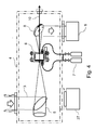
- the proposed Free-Electron Laser may include a drive laser system 1 for generating high energy laser pulses at a high repetition rate of the order of 1 MHz and delivering intense laser pulses 3 compressed through a pulse compressor chamber 2 into a laser plasma accelerator chamber 4.
- a laser-driven Free-Electron Laser can be used as an Extreme UltraViolet light source.
- Figure 2 shows an item of drive laser system 1 for producing high-energy laser pulses.
- a low-energy laser pulse 810 is produced by an oscillator 81.
- This pulse 810 is then stretched out in time, according to the chirped pulse amplification (CPA) technique, by a stretching device 82, comprising a pair of diffraction gratings 821 and 822, having the effect of offsetting in time the various spectral components of the original low-energy pulse 810.
- the stretched pulse 820 then has a lower peak power and a longer duration of the pulse 810.
- This laser pulse 820 is then distributed in a plurality of amplifying fibres 831 forming a first amplifying stage 83 of the fibre-type laser amplifier.
- the various fibres are separated from one another so as to make it possible to cool them effectively.
- Each of the amplifying fibres 831 comprises a core made from doped material, and is optically pumped, so as to optically amplify the laser pulse flowing in the fibre.
- the pulse passing through each of these amplifying fibres 831 is then amplified, and is then itself distributed in a plurality of amplifying fibres 841 forming the second amplification stage 84 of the fibre-type laser amplifier.
- the pulse passing through each of these amplifying fibres 841 is amplified and is then itself distributed in a plurality of amplifying fibres 851 forming the third amplification stage 85 of the fibre-type laser amplifier.
- the pulse is amplified in a plurality of fibres independent of one another and then divided so that pulses of lower power are transmitted to each of the higher-level amplification fibres.
- the third and last amplification stage 85 then comprises a very large number of amplifying fibres, for example around 10 6 .
- Each of the amplifying fibres of this third stage is extended by a transmission fibre having a very low loss level.
- the transmission fibres are collected together in a cluster 86 so that the pulses emerging from each of the ends of these transmission fibres are emitted in parallel and juxtaposed. These pulses then form a single amplified global pulse 860.
- This amplified global pulse 860 is compressed timewise by a compressor 87, located in the pulse compressor chamber 2.
- This compressor 87 comprises a pair of diffraction gratings 871 and 872, grouping together in time the various spectral components of the pulse.
- the pulse 3 emerging from this temporal compressor 17 then has a very high energy and very short duration.
- the ultrashort intense laser pulse 3 is focused by an off-axis parabolic mirror 5 on the entrance of a two-stage gas cell 6, of which the first cell referred to an injector is filled with a mixed gas, e.g., helium gas mixed with nitrogen, and the second cell referred to as an accelerator is filled with a pure gas, e.g., hydrogen or helium.
- a mixed gas e.g., helium gas mixed with nitrogen
- an accelerator e.g., hydrogen or helium.
- the gases are fed through a gas flow control system 7 to the two-stage gas cell separately at the different pressures.
- the said laser pulse 3 excites large-amplitude plasma wakefields, of which an accelerating electric field can trap plasma electrons exclusively out of the inner shell electrons and accelerate them owing to ionization-induced injection.
- a pre-accelerated electron beam 10 from the injector is further accelerated to the relativistic energy of the order of 1 GeV in the accelerator stage of the gas cell 6, where the laser pulse generates plasma wakefields of the order of 1 GV/cm.
- a transmitted laser light is directed through a mirror with a beam hole 8 to a recovery box 9 that includes diagnostics and absorbers of the transmitted laser pulses.
- This plasma accelerator is particularly advantageous when it is combined with a fiber-based laser, a beam focusing system, an undulator and a beam separator system according to the invention.
- a laser plasma accelerator comprising a first gas cell filled with mixed gas, and a second gas cell filled with pure helium gas can also be combined with an other type of laser, for producing relativistic electron beams.
- the output electron beam 10 from the laser plasma accelerator chamber 4 is transported into an undulator 13 through a beam focusing system 12, installed in a radiation chamber 11.
- a beam focusing system 12 installed in a radiation chamber 11.
- the electron beam 10 focused by quadrupole magnetic field of the beam focusing system 12 generates the resonantly amplified Extreme UltraViolet radiation 14 due to self-amplified spontaneous emission (SASE) mechanism when passing through the alternating dipole magnetic fields of the undulator 13 that force the electron bunch on a sinusoidal trajectory.
- SASE self-amplified spontaneous emission
- the electron bunch After passing through the undulator 13, the electron bunch is decelerated so strongly that it becomes non-resonant and could not contribute to the amplification of the Extreme UltraViolet radiation, i.e., the onset of saturation.
- the decelerated electron beam 10 is separated from the Extreme UltraViolet radiation 14 in the dipole magnetic field of the deflection magnet 16 and dumped to a beam dump 17, while the saturated Extreme UltraViolet radiation 14 is extracted from a beam separation chamber 15 and directed to a Extreme UltraViolet lithography scanner/stepper.
- Fig. 3 shows schematically a two-stage gas cell 6 comprising an injector stage 21 and an accelerator stage 24 for efficient electron trapping and acceleration in laser wakefields.
- the two-stage gas cell is set up in a laser plasma accelerator chamber 4 and a compressed laser pulse 3 from the pulse compressor chamber 2 is focused on the entrance of the injector gas cell by an off-axis parabolic mirror 5 with a F-number, e.g., 20.
- the injector cell 21 is filled with a mixed gas, e.g., 98% He and 2% N 2 , fed through a gas feedthrough 20 from the gas flow control system 7.
- the accelerator cell 24 is filled with a pure gas, e.g. H 2 or He, fed through a gas feedthrough 24 from the gas flow control system 7.
- a length of the accelerator stage is variably adjusted with a bellows structure 25 driven by a motorized actuator 26.
- the laser plasma accelerator chamber 4 is pump out by a vacuum pump system 27 to keep an inside pressure of 10 -3 -10 -4 Pa.
- Fig. 5 illustrates schematically a physical process 100 for the wakefield excitation and electron trapping and acceleration in wakefields, which are generated when an intense laser pulse propagates a neutral mixed gas in the injector 21.
- the evolution of plasma electron density is shown in the upper plot 101 and the excited longitudinal wakefield is shown in the lower plot 102.
- He and the outer shell electrons up to N 5+ are fully ionized in the leading front of the laser pulse with intensity 1.5 ⁇ 10 16 W/cm 2 to produce plasma electrons in the outer region of the laser pulse, of which the boundary is indicated by a thin dotted line 103.
- Plasma electrons contained in the boundary 103 are blown out by radiation pressure (ponderomotive force) of the laser pulse 3 with the relativistic intensity a 0 ? 1 and form a narrow dense electron sheath surrounding a spherical ion column behind the laser pulse, often referred to as a bubble 105.
- Such charge separation generates a strong longitudinal electric field 110 of the order of 100 GV/m at a plasma electron density of 10 18 cm -3 , which is three orders of magnitude higher than an accelerating field of conventional RF accelerators.
- an electron undergoes a strong focusing force simultaneously.
- electrons 10 are trapped into a bubble, they are efficiently accelerated up to high energy of the order of 1 GeV over a dephasing length of the order of 1 cm, where accelerated electrons outrun a proper accelerating phase.
- the said inner shell electrons from ionized N 6+ and N 7+ are located near the bubble center on the propagation axis, where the wake potential is a maximum and the expelling ponderomotive force of the laser pulse is a minimum. Contrary to pre-ionized free electrons, whose trajectories move along a narrow sheath outside the bubble, the ionized electrons emitted from the inner shell move close to the bubble axis toward the back of the bubble where the wake potential is a minimum, and eventually trapped into the wakefield in condition that electrons gain a sufficient kinetic energy required for trapping, as shown in the electron trajectory 106, while the electron shown in the trajectory 107, ionized earlier and off-axis, slips over the potential well and is not trapped.
- This mechanism called as ionization-induced injection occurs at the intensity as low as the optical field ionization threshold for the inner shell electrons of impurity gas and significantly increases the trapped charge.
- amplitudes of the betatron oscillation after trapping decrease compared to the self-injection from the electron sheath.
- the number of trapped electrons scales as N e [ ⁇ m -2 ]: 8 ⁇ 10 7 ⁇ N k p L mix ( n e / n c ) 1/2 for ⁇ N k p L mix ⁇ 2.
- the energy spread is also proportional to both the mixed gas length and the nitrogen concentration.
- the important parameters of a laser plasma accelerator for reaching a given energy E b are summarized as follows:
- the pulse duration required for satisfying a dephasing length longer than a pump depletion length is ⁇ L ⁇ 18 fs ⁇ ⁇ self 1 / 2 ⁇ L 1 ⁇ ⁇ ⁇ m ⁇ E b / ⁇ 200 ⁇ MeV 1 / 2
- the matched spot radius is given by r m ⁇ 3.9 ⁇ ⁇ m ⁇ R m ⁇ self ⁇ a 0 ⁇ L 1 ⁇ ⁇ ⁇ m ⁇ E b / ⁇ 200 ⁇ MeV 1 / 2
- a loaded charge is calculated as Q b ; e 4 ⁇ k L ⁇ r e ⁇ ⁇ b ⁇ k p 2 ⁇ ⁇ b 2 1 - ⁇ b ⁇ E z E 0 ⁇ n c n e 1 / 2 ⁇ 76 pC ⁇ ⁇ b ⁇ k p 2 ⁇ ⁇ b 2 1 - ⁇ b ⁇ E z E 0 ⁇ n e 10 18 ⁇ cm - 3 - 1 / 2 .
- the loaded charge is given by Q b ⁇ 55 pC ⁇ ⁇ b ⁇ k p 2 ⁇ ⁇ b 2 ⁇ self 1 / 2 ⁇ 1 - ⁇ b ⁇ L 1 ⁇ ⁇ ⁇ m ⁇ E b / ⁇ 200 ⁇ MeV 1 / 2 ⁇ 55 pC ⁇ 1 - ⁇ 2 ⁇ 3 / 2 ⁇ k p 2 ⁇ ⁇ b 2 ⁇ self 1 / 2 ⁇ L 1 ⁇ ⁇ ⁇ m ⁇ E b 200 ⁇ MeV 1 / 2 .
- Beam transport and imaging from the laser plasma accelerator 6 to the undulator 13 is provided by a beam focusing system 12 with short focal length.
- FIG. 6 illustrates schematically a twelve segments Halbach-type PMQ 31, 32 of a set of the quadrupole magnet 36, including a housing 33, 34 and a bracket 35 for supporting and positioning the PMQ.
- the quadrupole field is composed of four radially wedges of permanent magnet material 31, e.g., Nd 2 Fe 14 B or SmCO, with a high remanent field, of which the direction of magnetization is indicated by arrows.
- the outer field closure is formed by eight wedges of permanent magnet material 32.
- the beam focusing system 12 comprises two to four permanent quadrupole magnets (PMQ), e.g. a doublet (FD), a triplet (FDF), or a quadruplet (FFDD) 36-39 installed into a housing chamber 46 with water cooling tubes 44.
- PMQ permanent quadrupole magnets
- the longitudinal position of each permanent quadrupole magnet (PMQ) along the electron beam axis is optimized with a computer controlled mover system 40-43, comprising a vacuum linear motion manipulator driven by a stepping motor. Alignment of permanent quadrupole magnets (PMQ) is precisely constrained by a rail system 45.
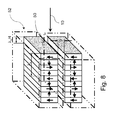
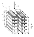
- a planar undulator comprising alternating dipole magnets 52 is used, e.g., a pure permanent magnet (PPM) undulator with Nd 2 Fe 14 B blocks 50 as shown in Fig. 8 or a hybrid undulator comprising pure permanent magnets 50 and ferromagnetic poles 51 as shown in Fig. 9 , e.g. a high saturation cobalt steel such as vanadium permendur or a simple iron.
- PPM permanent magnet
- a hybrid undulator comprising pure permanent magnets 50 and ferromagnetic poles 51 as shown in Fig. 9 , e.g. a high saturation cobalt steel such as vanadium permendur or a simple iron.
- the thickness of the pole and magnet is optimized in order to maximize the peak field.
- the arrows represent the direction of magnetization in the magnet blocks, of which a period is ⁇ u .
- the minimum distance between the magnet jaws is a gap g .
- the undulator 13 comprises a rectangular box frame 53, a gap adjusting mechanism 54 and cooling elements 55.
- the permanent magnet blocks 52 is attached to a thick base plate of the box frame 53 made of aluminium material.
- the alignment and gap of the undulator are adjusted by controlling the distance between two base plates of the box frame 53 with 4 or 6 adjusting mechanisms 54.
- Two monolithic water cooling elements 55 fabricated from tubing are connected to each magnet block 52.
- a decelerated electron beam 10 after saturation is bent by a dipole field of permanent magnet (a beam separator 16) made of NdFeB material and dumped to a beam dump 17 made of copper with a water cooling element 56.
- the permanent magnet dipole (PMD) 16 e.g., Halbach-type permanent magnet dipole, comprises 8 wedges of the NdFeB material, of which the magnetization direction is shown by the arrows in Fig. 11B .
- the mechanical precision and field accuracy of the permanent magnet dipole 16 can be achieved by the insertion of a nonmagnetic precision cylinder 57 into the center of the permanent magnet dipole and by the housing case 58 outside the permanent magnet dipole.
- the electron beam 10 bent by the permanent magnet dipole field 16 is dumped to the copper beam dump 17, while the Extreme UltraViolet radiation 14 is extracted through a narrow Extreme UltraViolet output hole 59 machined in the beam dump 17 at the edge of the permanent magnet dipole bore.
- the Free-Electron Laser device comprising the beam focusing system 12, the undulator 13 and the beam separator 16 and beam dump 17 is installed into vacuum chambers 11, 15 with vacuum pumping systems 28, 29 that maintain a pressure of the order of 10 -4 Pa inside the chamber.
- the beam dump 17 connected to the beam separator 16 forms a monolithic device.
- a design of Free-Electron Laser based Extreme UltraViolet light source is made by the one-dimensional Free-Electron Laser theory as follows.
- ⁇ FEL 1 2 ⁇ ⁇ ⁇ I b I A ⁇ ⁇ u ⁇ K u ⁇ A u 2 ⁇ ⁇ b 2 1 / 3
- I b is the beam current
- I A 17kA is the Alfven current
- ⁇ b is the root mean square (r.m.s) transverse size of the electron bunch
- ⁇ ⁇ b 2 / ⁇ is the beta function provided by the guiding field (undulator plus external focusing) and ⁇ n is the normalized emittance defined as ⁇ n ⁇ ⁇ assuming that a beta function is constant along the length of the undulator.
- L gain ⁇ u 4 ⁇ ⁇ ⁇ 3 ⁇ ⁇ FEL ⁇ 1 + ⁇ 2 .
- LPA Laser Plasma Accelerator
- LPA Laser Plasma Accelerator
- LPA Laser Plasma Accelerator
- LPA Laser Plasma Accelerator
- LPA Laser Plasma Accelerator
- LPA Laser Plasma Accelerator
- LPA Laser Plasma Accelerator
- Free-Electron Laser parameters for Case A to E producing the Extreme UltraViolet radiation of 1 kW at 6.7 nm wavelength are summarized as shown in Table 2.
- Table 2 Examples of the fiber laser driven Laser Plasma Accelerator (LPA) based Free-Electron Laser Extreme UltraViolet light source.
Landscapes
- Physics & Mathematics (AREA)
- Electromagnetism (AREA)
- Engineering & Computer Science (AREA)
- Plasma & Fusion (AREA)
- Optics & Photonics (AREA)
- Particle Accelerators (AREA)
- Lasers (AREA)
- Exposure And Positioning Against Photoresist Photosensitive Materials (AREA)
Priority Applications (3)
| Application Number | Priority Date | Filing Date | Title |
|---|---|---|---|
| EP13306235.6A EP2846422A1 (fr) | 2013-09-09 | 2013-09-09 | Laser à électrons libres comprenant un accélérateur plasma par impulsion laser fournie par un laser à fibres |
| PCT/EP2014/069222 WO2015032995A1 (fr) | 2013-09-09 | 2014-09-09 | Laser à électrons libres piloté par un laser à fibres alimentant un accélérateur laser-plasma |
| US14/917,622 US9768580B2 (en) | 2013-09-09 | 2014-09-09 | Free-electron laser driven by fiber laser-based laser plasma accelerator |
Applications Claiming Priority (1)
| Application Number | Priority Date | Filing Date | Title |
|---|---|---|---|
| EP13306235.6A EP2846422A1 (fr) | 2013-09-09 | 2013-09-09 | Laser à électrons libres comprenant un accélérateur plasma par impulsion laser fournie par un laser à fibres |
Publications (1)
| Publication Number | Publication Date |
|---|---|
| EP2846422A1 true EP2846422A1 (fr) | 2015-03-11 |
Family
ID=49641695
Family Applications (1)
| Application Number | Title | Priority Date | Filing Date |
|---|---|---|---|
| EP13306235.6A Withdrawn EP2846422A1 (fr) | 2013-09-09 | 2013-09-09 | Laser à électrons libres comprenant un accélérateur plasma par impulsion laser fournie par un laser à fibres |
Country Status (3)
| Country | Link |
|---|---|
| US (1) | US9768580B2 (fr) |
| EP (1) | EP2846422A1 (fr) |
| WO (1) | WO2015032995A1 (fr) |
Cited By (3)
| Publication number | Priority date | Publication date | Assignee | Title |
|---|---|---|---|---|
| CN105555008A (zh) * | 2015-12-03 | 2016-05-04 | 中国工程物理研究院激光聚变研究中心 | 一种正电子束流传输系统 |
| CN113300198A (zh) * | 2021-05-14 | 2021-08-24 | 江苏师范大学 | 单频窄线宽分布式反馈脉冲光纤激光器及其实现方法 |
| CN113455107A (zh) * | 2018-11-02 | 2021-09-28 | 埃因霍温科技大学 | 强、窄带、完全相干、软x射线的可调谐源 |
Families Citing this family (12)
| Publication number | Priority date | Publication date | Assignee | Title |
|---|---|---|---|---|
| SI3633683T1 (sl) * | 2014-10-13 | 2021-09-30 | Tae Technologies, Inc. | Postopek za združevanje in komprimiranje kompaktnih torusov |
| FR3028093B1 (fr) * | 2014-11-05 | 2019-05-31 | Ecole Polytechnique | Lentille laser-plasma |
| US9844124B2 (en) * | 2015-03-12 | 2017-12-12 | Globalfoundries Inc. | Method, apparatus and system for using free-electron laser compatible EUV beam for semiconductor wafer metrology |
| GB201617173D0 (en) * | 2016-10-10 | 2016-11-23 | Univ Strathclyde | Plasma accelerator |
| KR102031796B1 (ko) * | 2016-12-28 | 2019-10-15 | 기초과학연구원 | 길이조절이 가능한 가스 타겟 및 이를 포함하는 레이저-기체 반응 시스템 |
| CN106873022A (zh) * | 2017-03-20 | 2017-06-20 | 中国科学院上海光学精密机械研究所 | 一种适用于激光尾场电子加速的高分辨率电子能谱仪 |
| JPWO2018198227A1 (ja) * | 2017-04-26 | 2020-05-14 | ギガフォトン株式会社 | Euv光生成装置 |
| RU184178U1 (ru) * | 2018-03-12 | 2018-10-18 | Дмитрий Николаевич Харитонов | Сверхпроводниковый эмиссионный ондулятор |
| US11037765B2 (en) * | 2018-07-03 | 2021-06-15 | Tokyo Electron Limited | Resonant structure for electron cyclotron resonant (ECR) plasma ionization |
| CA3134044A1 (fr) * | 2019-03-18 | 2020-09-24 | Tae Technologies, Inc. | Systemes et procedes pour des electrons acceleres par champ de sillage laser compact et rayons x |
| US11483919B2 (en) * | 2019-03-27 | 2022-10-25 | Huazhong University Of Science And Technology | System of electron irradiation |
| CN118033992B (zh) * | 2024-04-11 | 2024-06-25 | 深圳大学 | 极紫外光源 |
Citations (4)
| Publication number | Priority date | Publication date | Assignee | Title |
|---|---|---|---|---|
| US4761584A (en) | 1987-01-30 | 1988-08-02 | The United States Of America As Represented By The United States Department Of Energy | Strong permanent magnet-assisted electromagnetic undulator |
| US5019863A (en) | 1987-09-30 | 1991-05-28 | Amoco Corporation | Wedged-pole hybrid undulator |
| US20120228526A1 (en) | 2007-07-13 | 2012-09-13 | Vaschenko Georgiy O | Laser produced plasma euv light source |
| WO2013023053A1 (fr) | 2011-08-09 | 2013-02-14 | Cornell University | Système ondulateur compact et procédés |
-
2013
- 2013-09-09 EP EP13306235.6A patent/EP2846422A1/fr not_active Withdrawn
-
2014
- 2014-09-09 US US14/917,622 patent/US9768580B2/en active Active
- 2014-09-09 WO PCT/EP2014/069222 patent/WO2015032995A1/fr active Application Filing
Patent Citations (4)
| Publication number | Priority date | Publication date | Assignee | Title |
|---|---|---|---|---|
| US4761584A (en) | 1987-01-30 | 1988-08-02 | The United States Of America As Represented By The United States Department Of Energy | Strong permanent magnet-assisted electromagnetic undulator |
| US5019863A (en) | 1987-09-30 | 1991-05-28 | Amoco Corporation | Wedged-pole hybrid undulator |
| US20120228526A1 (en) | 2007-07-13 | 2012-09-13 | Vaschenko Georgiy O | Laser produced plasma euv light source |
| WO2013023053A1 (fr) | 2011-08-09 | 2013-02-14 | Cornell University | Système ondulateur compact et procédés |
Non-Patent Citations (24)
| Title |
|---|
| A. PAK ET AL: "Injection and Trapping of Tunnel-Ionized Electrons into Laser-Produced Wakes", PHYSICAL REVIEW LETTERS, vol. 104, no. 2, 1 January 2010 (2010-01-01), XP055101496, ISSN: 0031-9007, DOI: 10.1103/PhysRevLett.104.025003 * |
| A. PAK; K. A. MARSH; S. F. MARTINS; W. LU; W. B. MORI; C. JOSHI: "Injection and Trapping of Tunnel-Ionized Electrons into Laser-ProducedWakes", PHYS. REV. LETT., vol. 104, no. 025003, 2010 |
| B. B. POLLOCK; C. E. CLAYTON; J. E. RALPH; F. ALBERT; A. DAVIDSON; L. DIVOL; C.FILIP; S. H. GLENZER; K. HERPOLDT; W. LU: "Demonstration of a Narrow Energy Spread, similar to 0.5 GeV Electron Beam from a Two-Stage Laser Wakefield Accelerator", PHYS. REV. LETT., vol. 107, 2011, pages 045001 |
| C. MCGUFFEY ET AL: "Ionization Induced Trapping in a Laser Wakefield Accelerator", PHYSICAL REVIEW LETTERS, vol. 104, no. 2, 1 January 2010 (2010-01-01), XP055101503, ISSN: 0031-9007, DOI: 10.1103/PhysRevLett.104.025004 * |
| C. MCGUFFEY; A. G. R. THOMAS; W. SCHUMAKER; T. MATSUOKA; V. CHVYKOV; F.J. DOLLAR; G. KALINTCHENKO; V. YANOVSKY; A. MAKSIMCHUK; K.: "Ionization Induced Trapping in aLaser Wakefield Accelerator", PHYS. REV. LETT., vol. 104, 2010, pages 025004 |
| C. PAGANI; E.L. SALDIN; E.A. SCHNEIDMILLER; M.V. YURKOV: "Design considerations of 10 kW-scale extreme ultraviolet SASE FEL for lithography", NUCLEAR INSTRUMENTS AND METHODS IN PHYSICS RESEARCH A, vol. 463, 2001, pages 9 - 25 |
| C. XIA; J. LIU; W. WANG; H. LU; W. CHENG; A. DENG; W. LI; H. ZHANG; X.LIANG; Y. LENG: "Effects of self-focusing on tunnel-ionization-induced injection in a laserwakefield accelerator", PHYS. PLASMAS, vol. 18, 2011, pages 113101 |
| G. MOUROU ET AL: "ICAN and 100GeV's Ascent", EURONNAC, MAY 2012 MEETING, CERN, 1 May 2012 (2012-05-01), pages 1 - 60, XP055101548, Retrieved from the Internet <URL:http://indico.cern.ch/event/187383/session/3/contribution/7/material/slides/0.pdf> [retrieved on 20140211] * |
| GÉRARD MOUROU: "Workshop IZEST 100GeV Ascent", May 2013 (2013-05-01), pages 1 - 18, XP055101549, Retrieved from the Internet <URL:https://gargantua.polytechnique.fr/siatel-web/linkto/mICYYYS74tY> [retrieved on 20140211] * |
| H.-P. SCHLENVOIGT ET AL: "A compact synchrotron radiation source driven by a laser-plasma wakefield accelerator", NATURE PHYSICS, vol. 4, no. 2, 9 December 2007 (2007-12-09), pages 130 - 133, XP055101295, ISSN: 1745-2473, DOI: 10.1038/nphys811 * |
| HAFZ NASR: "Laser-driven electron acceleration research at APRI and future application to compact light sources", JOURNAL OF THE KOREAN PHYSICAL SOCIETY, vol. 56, no. 11, 15 January 2010 (2010-01-15), pages 241, XP055101292, ISSN: 0374-4884, DOI: 10.3938/jkps.56.241 * |
| H-P SCHLENVOIGT ET AL: "Synchrotron Radiation From Laser-Accelerated Monoenergetic Electrons", IEEE TRANSACTIONS ON PLASMA SCIENCE, IEEE SERVICE CENTER, PISCATAWAY, NJ, US, vol. 36, no. 4, 1 August 2008 (2008-08-01), pages 1773 - 1781, XP011232933, ISSN: 0093-3813, DOI: 10.1109/TPS.2008.927146 * |
| J. K. LIM; P. FRIGOLA; G. TRAVISH; J. B. ROSENZWEIG; S. G. ANDERSON; W. J. BROWN; J. S. JACOB; C. L. ROBBINS; A. M. TREMAINE: "Adjustable, short focal length permanent-magnet quadrupole based electron beam final focus system", PHYSICAL REVIEW SPECIAL TOPICS - ACCELERATORS AND BEAMS, vol. 8, 2005, pages 1 - 17 |
| J. S. LIU; C. Q. XIA; W. T. WANG; H. Y. LU; C. WANG; A. H. DENG; W. T. LI; H. ZHANG; X. Y. LIANG; Y. X. LENG: "All-Optical Cascaded Laser WakefieldAccelerator Using Ionization-Induced Injection", PHYS. REV. LETT., vol. 107, 2011, pages 035001 |
| KAZUHISA NAKAJIMA; HAIYANG LU; XUEYAN ZHAO; BAIFEI SHEN; RUXIN LI; ZHIZHAN XU: "100-GeV large scale laser plasma electron acceleration by a multi-PW laser", CHINESE OPTICS LETTERS, vol. 11, no. 1, 2013, pages 1 - 15 |
| M. CHEN; E. ESAREY; C. B. SCHROEDER; C. G. R. GEDDES; W. P. LEEMANS: "Theory of ionization-induced trapping in laser-plasma accelerators", PHYS. PLASMAS, vol. 19, 2012, pages 033101 |
| P. ELLEAUME; J. CHAVANNE; BART FAATZ, NUCLEAR INSTRUMENTS AND METHODS IN PHYSICS RESEARCH A, vol. 455, 2000, pages 503 - 523 |
| P. GASIOR: "Can ICAN can CERN into a can?: review study", PROCEEDINGS OF SPIE, vol. 8903, 25 October 2013 (2013-10-25), pages 89030N, XP055101289, ISSN: 0277-786X, DOI: 10.1117/12.2035369 * |
| PUKHOV A ET AL: "The bubble regime of laser-plasma acceleration: monoenergetic electrons and the scalability; The bubble regime of laser-plasma acceleration", PLASMA PHYSICS AND CONTROLLED FUSION, IOP, BRISTOL, GB, vol. 46, no. 12B, 1 December 2004 (2004-12-01), pages B179 - B186, XP020049654, ISSN: 0741-3335, DOI: 10.1088/0741-3335/46/12B/016 * |
| T. EICHNER; F. GRUNER; S. BECKER; M. FUCHS; D. HABS; R. WEINGARTNER; U. SCHRAMM; H. BACKE; P. KUNZ; W. LAUTH: "Miniature magnetic devices for laser-based, table-top free-electron lasers", PHYSICAL REVIEW SPECIAL TOPICS - ACCELERATORS AND BEAMS, vol. 10, 2007, pages 082401 |
| TOSHIKI TAJIMA ET AL: "ICAN: The Next Laser Powerhouse", OPTICS AND PHOTONICS NEWS, 1 May 2013 (2013-05-01), pages 36 - 43, XP055101291, DOI: http://dx.doi.org/10.1364/OPN.24.5.000036 * |
| VIEIRA J F ET AL: "Three-Dimensional Structure of the Laser Wakefield Accelerator in the Blowout Regime", IEEE TRANSACTIONS ON PLASMA SCIENCE, IEEE SERVICE CENTER, PISCATAWAY, NJ, US, vol. 36, no. 4, 1 August 2008 (2008-08-01), pages 1124 - 1125, XP011232963, ISSN: 0093-3813, DOI: 10.1109/TPS.2008.922930 * |
| WIGGINS S M ET AL: "High quality electron beams from a laser wakefield accelerator", CONFERENCE ON LASERS AND ELECTRO-OPTICS (CLEO) AND QUANTUM ELECTRONICS AND LASER SCIENCE CONFERENCE (QELS), 2010 : 16 - 21 MAY 2010, SAN JOSE, CA, USA, IEEE, PISCATAWAY, NJ , USA, 16 May 2010 (2010-05-16), pages 1 - 2, XP031701440, ISBN: 978-1-55752-890-2 * |
| YOSHITAMA H ET AL: "PHYSICS OF GASES, PLASMAS, AND ELECTRIC DISCHARGES; Self-Injection and Acceleration of Monoenergetic Electron Beams from Laser Wakefield Accelerators in a Highly Relativistic Regime", CHINESE PHYSICS LETTERS, INSTITUTE OF PHYSICS PUBLISHING, BRISTOL, GB, vol. 25, no. 8, 1 August 2008 (2008-08-01), pages 2938 - 2941, XP020141951, ISSN: 0256-307X, DOI: 10.1088/0256-307X/25/8/056 * |
Cited By (4)
| Publication number | Priority date | Publication date | Assignee | Title |
|---|---|---|---|---|
| CN105555008A (zh) * | 2015-12-03 | 2016-05-04 | 中国工程物理研究院激光聚变研究中心 | 一种正电子束流传输系统 |
| CN113455107A (zh) * | 2018-11-02 | 2021-09-28 | 埃因霍温科技大学 | 强、窄带、完全相干、软x射线的可调谐源 |
| CN113300198A (zh) * | 2021-05-14 | 2021-08-24 | 江苏师范大学 | 单频窄线宽分布式反馈脉冲光纤激光器及其实现方法 |
| CN113300198B (zh) * | 2021-05-14 | 2023-12-01 | 江苏师范大学 | 单频窄线宽分布式反馈脉冲光纤激光器及其实现方法 |
Also Published As
| Publication number | Publication date |
|---|---|
| US20160226212A1 (en) | 2016-08-04 |
| US9768580B2 (en) | 2017-09-19 |
| WO2015032995A1 (fr) | 2015-03-12 |
Similar Documents
| Publication | Publication Date | Title |
|---|---|---|
| US9768580B2 (en) | Free-electron laser driven by fiber laser-based laser plasma accelerator | |
| Ferri et al. | High-brilliance betatron γ-ray source powered by laser-accelerated electrons | |
| KR102340172B1 (ko) | Euv용 자유 전자 레이저 방사원 | |
| US10212796B2 (en) | X-ray pulse source and method for generating X-ray pulses | |
| US20230006412A1 (en) | Free electron laser orbital debris removal system | |
| Carlsten et al. | New source technologies and their impact on future light sources | |
| Labat et al. | Robustness of a plasma acceleration based free electron laser | |
| Nakajima | Conceptual designs of a laser plasma accelerator-based EUV-FEL and an all-optical Gamma-beam source | |
| Pagani et al. | Design considerations of a MW-scale, high-efficiency, industrial-use, ultraviolet FEL amplifier | |
| Pogorelsky | Terawatt picosecond CO 2 laser technology for strong field physics applications | |
| Schreiber | Soft and hard x-ray sase free electron lasers | |
| Rossbach | The TESLA Free Electron Laser-Concept and Status | |
| Corsini et al. | Considerations on a FEL based on LEP Superconducting Cavities | |
| Leach | The free electron laser, offspring of synchrotron radiation | |
| Khan et al. | Accelerator-Based Photon Sources | |
| Benson | Free-electron lasers push into new frontiers | |
| Pogorelsky et al. | Emerging terawatt picosecond CO/sub 2/laser technology and possible applications in accelerator physics | |
| Zvorykin | NG Basov's role in the development of excimer lasers: a half-century history from the launch of the first Xe2 laser at the Lebedev Physical Institute to modern laser systems | |
| Albert et al. | Betatron x-ray production in mixed gases | |
| Huang et al. | Transverse Gradient Undulator to Enhance the FEL Performance for a Laser Plasma Accelerator | |
| Boulton | Optimisation of energy and brightness transformer stages in a plasma Wakefield accelerator | |
| Couprie et al. | Progress Towards Laser Plasma Electron Based Free Electron Laser on COXINEL | |
| Lee et al. | Design and construction of a far-infrared free-electron laser driven by a microtron | |
| Socol et al. | 13.5 nm free-electron laser for EUV lithography | |
| Castro | Overview of SASE experiments |
Legal Events
| Date | Code | Title | Description |
|---|---|---|---|
| 17P | Request for examination filed |
Effective date: 20130909 |
|
| AK | Designated contracting states |
Kind code of ref document: A1 Designated state(s): AL AT BE BG CH CY CZ DE DK EE ES FI FR GB GR HR HU IE IS IT LI LT LU LV MC MK MT NL NO PL PT RO RS SE SI SK SM TR |
|
| AX | Request for extension of the european patent |
Extension state: BA ME |
|
| PUAI | Public reference made under article 153(3) epc to a published international application that has entered the european phase |
Free format text: ORIGINAL CODE: 0009012 |
|
| STAA | Information on the status of an ep patent application or granted ep patent |
Free format text: STATUS: THE APPLICATION IS DEEMED TO BE WITHDRAWN |
|
| 18D | Application deemed to be withdrawn |
Effective date: 20150912 |