EP2846170A1 - Ultrasonic measurement apparatus, ultrasonic imaging apparatus, and ultrasonic measurement method - Google Patents
Ultrasonic measurement apparatus, ultrasonic imaging apparatus, and ultrasonic measurement method Download PDFInfo
- Publication number
- EP2846170A1 EP2846170A1 EP14183898.7A EP14183898A EP2846170A1 EP 2846170 A1 EP2846170 A1 EP 2846170A1 EP 14183898 A EP14183898 A EP 14183898A EP 2846170 A1 EP2846170 A1 EP 2846170A1
- Authority
- EP
- European Patent Office
- Prior art keywords
- channel
- ultrasonic
- reception signal
- error
- reception
- Prior art date
- Legal status (The legal status is an assumption and is not a legal conclusion. Google has not performed a legal analysis and makes no representation as to the accuracy of the status listed.)
- Withdrawn
Links
- 238000005259 measurement Methods 0.000 title claims abstract description 19
- 238000003384 imaging method Methods 0.000 title claims description 28
- 238000000691 measurement method Methods 0.000 title claims description 4
- 238000012545 processing Methods 0.000 claims abstract description 129
- 238000001514 detection method Methods 0.000 claims abstract description 58
- 239000000523 sample Substances 0.000 claims description 26
- 230000003044 adaptive effect Effects 0.000 abstract description 25
- 230000000694 effects Effects 0.000 abstract description 11
- 108091006146 Channels Proteins 0.000 description 204
- 230000005540 biological transmission Effects 0.000 description 38
- 238000012935 Averaging Methods 0.000 description 15
- 230000000875 corresponding effect Effects 0.000 description 12
- 238000000034 method Methods 0.000 description 12
- 230000006870 function Effects 0.000 description 9
- 238000004364 calculation method Methods 0.000 description 8
- 238000005070 sampling Methods 0.000 description 8
- 230000035945 sensitivity Effects 0.000 description 8
- 239000000470 constituent Substances 0.000 description 6
- 239000010408 film Substances 0.000 description 6
- 239000000758 substrate Substances 0.000 description 6
- 238000001914 filtration Methods 0.000 description 5
- 239000010409 thin film Substances 0.000 description 5
- 230000009466 transformation Effects 0.000 description 5
- 230000006866 deterioration Effects 0.000 description 4
- 238000002592 echocardiography Methods 0.000 description 4
- VYPSYNLAJGMNEJ-UHFFFAOYSA-N Silicium dioxide Chemical compound O=[Si]=O VYPSYNLAJGMNEJ-UHFFFAOYSA-N 0.000 description 3
- 230000015572 biosynthetic process Effects 0.000 description 3
- 238000004891 communication Methods 0.000 description 3
- 238000010586 diagram Methods 0.000 description 3
- 229910052451 lead zirconate titanate Inorganic materials 0.000 description 3
- HFGPZNIAWCZYJU-UHFFFAOYSA-N lead zirconate titanate Chemical compound [O-2].[O-2].[O-2].[O-2].[O-2].[Ti+4].[Zr+4].[Pb+2] HFGPZNIAWCZYJU-UHFFFAOYSA-N 0.000 description 3
- 239000011159 matrix material Substances 0.000 description 3
- 239000002184 metal Substances 0.000 description 3
- 229910052751 metal Inorganic materials 0.000 description 3
- XUIMIQQOPSSXEZ-UHFFFAOYSA-N Silicon Chemical compound [Si] XUIMIQQOPSSXEZ-UHFFFAOYSA-N 0.000 description 2
- MCMNRKCIXSYSNV-UHFFFAOYSA-N Zirconium dioxide Chemical compound O=[Zr]=O MCMNRKCIXSYSNV-UHFFFAOYSA-N 0.000 description 2
- 230000003321 amplification Effects 0.000 description 2
- 238000006243 chemical reaction Methods 0.000 description 2
- 229910052681 coesite Inorganic materials 0.000 description 2
- 229910052906 cristobalite Inorganic materials 0.000 description 2
- 238000005516 engineering process Methods 0.000 description 2
- 229910052746 lanthanum Inorganic materials 0.000 description 2
- 239000000463 material Substances 0.000 description 2
- 239000012528 membrane Substances 0.000 description 2
- 238000012986 modification Methods 0.000 description 2
- 230000004048 modification Effects 0.000 description 2
- 238000003199 nucleic acid amplification method Methods 0.000 description 2
- 238000001020 plasma etching Methods 0.000 description 2
- 238000003672 processing method Methods 0.000 description 2
- 229910052710 silicon Inorganic materials 0.000 description 2
- 239000010703 silicon Substances 0.000 description 2
- 230000007480 spreading Effects 0.000 description 2
- 229910052682 stishovite Inorganic materials 0.000 description 2
- 229910052905 tridymite Inorganic materials 0.000 description 2
- 229910003781 PbTiO3 Inorganic materials 0.000 description 1
- 229910010252 TiO3 Inorganic materials 0.000 description 1
- RTAQQCXQSZGOHL-UHFFFAOYSA-N Titanium Chemical compound [Ti] RTAQQCXQSZGOHL-UHFFFAOYSA-N 0.000 description 1
- 230000008901 benefit Effects 0.000 description 1
- 230000008859 change Effects 0.000 description 1
- 230000006835 compression Effects 0.000 description 1
- 238000007906 compression Methods 0.000 description 1
- 238000004590 computer program Methods 0.000 description 1
- 230000008602 contraction Effects 0.000 description 1
- 230000002596 correlated effect Effects 0.000 description 1
- 230000002542 deteriorative effect Effects 0.000 description 1
- NKZSPGSOXYXWQA-UHFFFAOYSA-N dioxido(oxo)titanium;lead(2+) Chemical compound [Pb+2].[O-][Ti]([O-])=O NKZSPGSOXYXWQA-UHFFFAOYSA-N 0.000 description 1
- 238000005401 electroluminescence Methods 0.000 description 1
- 238000005530 etching Methods 0.000 description 1
- 239000000284 extract Substances 0.000 description 1
- FZLIPJUXYLNCLC-UHFFFAOYSA-N lanthanum atom Chemical compound [La] FZLIPJUXYLNCLC-UHFFFAOYSA-N 0.000 description 1
- 229910052745 lead Inorganic materials 0.000 description 1
- 239000004973 liquid crystal related substance Substances 0.000 description 1
- 239000000377 silicon dioxide Substances 0.000 description 1
- 230000002123 temporal effect Effects 0.000 description 1
- 238000011144 upstream manufacturing Methods 0.000 description 1
Images


Classifications
-
- G—PHYSICS
- G01—MEASURING; TESTING
- G01S—RADIO DIRECTION-FINDING; RADIO NAVIGATION; DETERMINING DISTANCE OR VELOCITY BY USE OF RADIO WAVES; LOCATING OR PRESENCE-DETECTING BY USE OF THE REFLECTION OR RERADIATION OF RADIO WAVES; ANALOGOUS ARRANGEMENTS USING OTHER WAVES
- G01S7/00—Details of systems according to groups G01S13/00, G01S15/00, G01S17/00
- G01S7/52—Details of systems according to groups G01S13/00, G01S15/00, G01S17/00 of systems according to group G01S15/00
- G01S7/52017—Details of systems according to groups G01S13/00, G01S15/00, G01S17/00 of systems according to group G01S15/00 particularly adapted to short-range imaging
- G01S7/52023—Details of receivers
-
- G—PHYSICS
- G01—MEASURING; TESTING
- G01S—RADIO DIRECTION-FINDING; RADIO NAVIGATION; DETERMINING DISTANCE OR VELOCITY BY USE OF RADIO WAVES; LOCATING OR PRESENCE-DETECTING BY USE OF THE REFLECTION OR RERADIATION OF RADIO WAVES; ANALOGOUS ARRANGEMENTS USING OTHER WAVES
- G01S7/00—Details of systems according to groups G01S13/00, G01S15/00, G01S17/00
- G01S7/52—Details of systems according to groups G01S13/00, G01S15/00, G01S17/00 of systems according to group G01S15/00
- G01S7/52017—Details of systems according to groups G01S13/00, G01S15/00, G01S17/00 of systems according to group G01S15/00 particularly adapted to short-range imaging
- G01S7/52046—Techniques for image enhancement involving transmitter or receiver
- G01S7/52047—Techniques for image enhancement involving transmitter or receiver for elimination of side lobes or of grating lobes; for increasing resolving power
-
- A—HUMAN NECESSITIES
- A61—MEDICAL OR VETERINARY SCIENCE; HYGIENE
- A61B—DIAGNOSIS; SURGERY; IDENTIFICATION
- A61B8/00—Diagnosis using ultrasonic, sonic or infrasonic waves
- A61B8/44—Constructional features of the ultrasonic, sonic or infrasonic diagnostic device
- A61B8/4483—Constructional features of the ultrasonic, sonic or infrasonic diagnostic device characterised by features of the ultrasound transducer
- A61B8/4494—Constructional features of the ultrasonic, sonic or infrasonic diagnostic device characterised by features of the ultrasound transducer characterised by the arrangement of the transducer elements
-
- G—PHYSICS
- G01—MEASURING; TESTING
- G01S—RADIO DIRECTION-FINDING; RADIO NAVIGATION; DETERMINING DISTANCE OR VELOCITY BY USE OF RADIO WAVES; LOCATING OR PRESENCE-DETECTING BY USE OF THE REFLECTION OR RERADIATION OF RADIO WAVES; ANALOGOUS ARRANGEMENTS USING OTHER WAVES
- G01S15/00—Systems using the reflection or reradiation of acoustic waves, e.g. sonar systems
- G01S15/88—Sonar systems specially adapted for specific applications
- G01S15/89—Sonar systems specially adapted for specific applications for mapping or imaging
- G01S15/8906—Short-range imaging systems; Acoustic microscope systems using pulse-echo techniques
- G01S15/8909—Short-range imaging systems; Acoustic microscope systems using pulse-echo techniques using a static transducer configuration
- G01S15/8915—Short-range imaging systems; Acoustic microscope systems using pulse-echo techniques using a static transducer configuration using a transducer array
- G01S15/8925—Short-range imaging systems; Acoustic microscope systems using pulse-echo techniques using a static transducer configuration using a transducer array the array being a two-dimensional transducer configuration, i.e. matrix or orthogonal linear arrays
-
- G—PHYSICS
- G01—MEASURING; TESTING
- G01S—RADIO DIRECTION-FINDING; RADIO NAVIGATION; DETERMINING DISTANCE OR VELOCITY BY USE OF RADIO WAVES; LOCATING OR PRESENCE-DETECTING BY USE OF THE REFLECTION OR RERADIATION OF RADIO WAVES; ANALOGOUS ARRANGEMENTS USING OTHER WAVES
- G01S15/00—Systems using the reflection or reradiation of acoustic waves, e.g. sonar systems
- G01S15/88—Sonar systems specially adapted for specific applications
- G01S15/89—Sonar systems specially adapted for specific applications for mapping or imaging
- G01S15/8906—Short-range imaging systems; Acoustic microscope systems using pulse-echo techniques
- G01S15/8909—Short-range imaging systems; Acoustic microscope systems using pulse-echo techniques using a static transducer configuration
- G01S15/8915—Short-range imaging systems; Acoustic microscope systems using pulse-echo techniques using a static transducer configuration using a transducer array
- G01S15/8927—Short-range imaging systems; Acoustic microscope systems using pulse-echo techniques using a static transducer configuration using a transducer array using simultaneously or sequentially two or more subarrays or subapertures
-
- G—PHYSICS
- G01—MEASURING; TESTING
- G01S—RADIO DIRECTION-FINDING; RADIO NAVIGATION; DETERMINING DISTANCE OR VELOCITY BY USE OF RADIO WAVES; LOCATING OR PRESENCE-DETECTING BY USE OF THE REFLECTION OR RERADIATION OF RADIO WAVES; ANALOGOUS ARRANGEMENTS USING OTHER WAVES
- G01S7/00—Details of systems according to groups G01S13/00, G01S15/00, G01S17/00
- G01S7/52—Details of systems according to groups G01S13/00, G01S15/00, G01S17/00 of systems according to group G01S15/00
- G01S7/52017—Details of systems according to groups G01S13/00, G01S15/00, G01S17/00 of systems according to group G01S15/00 particularly adapted to short-range imaging
- G01S7/5205—Means for monitoring or calibrating
Definitions
- Adaptive beamforming is able to maximize the sensitivity of reception waves from a desired direction and to minimize the sensitivity of unwanted waves from directions other than the desired direction. That is, the sensitivity characteristics of reception waves can be adaptively changed and azimuth resolution can be improved.
- An advantage of some aspects of the invention is to provide a technology that prevents a decrease in the effects of adaptive beamforming, even in the case where some of the elements cannot correctly receive signals.
- An ultrasonic measurement apparatus includes a reception processing unit that receives, via an ultrasonic element array having a plurality of channels, an ultrasonic echo relating to an ultrasonic wave transmitted toward an object, as a reception signal for each channel; an error detection unit that performs error detection for each channel; a signal processing unit that performs weighted addition of a reception signal for each normal channel other than an error channel for which an error was detected, with a weight that depends on the reception signal for the normal channel; and an image generation unit that generates an image based on a signal obtained from the weighted addition.
- an error channel is detected and weighted addition processing on the reception signals of normal channels other than the error channel is executed according to the reception signal of each normal channel. Even in the case where there is an error channel, the influence of the reception signal of the error channel are thereby avoided, and a decrease in the effects of weighted addition processing such as adaptive beamforming can be prevented.
- the reception processing unit may receive an ultrasonic echo relating to the transmitted ultrasonic wave as the reception signal for each channel, whenever an ultrasonic wave for generating an image for one line is transmitted, the error detection unit may perform error detection for each channel, whenever the reception signal for each channel is received, the signal processing unit may perform weighted addition, whenever the reception signal for each channel is received, and the image generation unit may generate an image, whenever the reception signal for each channel is received.
- a fault or the like that occurs due to aged deterioration of individual channels or the like can thereby be accurately detected.
- adaptive beamforming is executed on the reception signals of normal channels for each line, the likelihood of a decrease in the effects of adaptive beamforming can be reduced.
- the error detection unit may detect a channel whose reception signal has a relatively low value as an error channel, based on a value of the received reception signal for each channel. Error channels can thereby be accurately detected, even if aged deterioration or the like occurs in all the channels.
- the error detection unit may detect a channel whose reception signal has a relatively low value as an error channel, based on a value of a reflection signal from a specific object in an ultrasonic probe that includes the ultrasonic element array, among the received reception signals for the respective channels. Error channels can thereby be accurately detected, without being affected by the external environment or the like.
- the error detection unit may detect a channel whose reception signal has a value less than a predetermined value as an error channel, based on a value of the received reception signal for each channel. Operational processing for performing relative comparison with other channels is thereby no longer necessary, enabling the processing time of error detection to be reduced.
- the signal-processing unit may determine whether the number of the detected error channels is less than or equal to a predetermined number, perform weighted addition of the reception signal for each normal channel with the weight that depends on the reception signal for the normal channel, if the number of detected error channels is less than or equal to the predetermined number, and perform weighted addition of the reception signal for each error channel and each normal channel with a predetermined fixed weight, if the number of detected error channels is not less than or equal to the predetermined number.
- Resolution can thereby be improved by executing normal beamforming, in the case where resolution would conversely decrease if weighted addition such as adaptive beamforming were executed.
- the signal processing unit may derive, as the weight that depends on the reception signal, a weight of each normal channel at which a variance of a value obtained by multiplying a weight of the normal channel and the reception signal of the normal channel is minimized.
- the weight of each channel can thereby be changed according to the incoming wave.
- An ultrasonic imaging apparatus includes a reception processing unit that receives, via an ultrasonic element array having a plurality of channels, an ultrasonic echo relating to an ultrasonic wave transmitted toward an object, as a reception signal for each channel; an error detection unit that performs error detection for each channel; a signal processing unit that performs weighted addition of a reception signal for each normal channel other than an error channel for which an error was detected, with a weight that depends on the reception signal for the normal channel; an image generation unit that generates an image based on a signal obtained from the weighted addition; and a display unit that displays the generated image.
- An ultrasonic measurement method includes receiving, via an ultrasonic element array having a plurality of channels, an ultrasonic echo relating to an ultrasonic wave transmitted toward an object, as a reception signal for each channel; performing error detection for each channel; performing weighted addition of a reception signal for each normal channel other than an error channel for which an error was detected, with a weight that depends on the reception signal for the normal channel; and generating an image based on a signal obtained from the weighted addition. Even in the case where there is an error channel, the influence of the reception signal of the error channel is thereby avoided, and a decrease in the effects of weighted addition processing such as adaptive beamforming can be prevented.
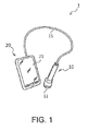
- Fig. 1 shows an exemplary external appearance of an ultrasonic imaging apparatus 1 according to an embodiment of the invention.
- the ultrasonic imaging apparatus 1 is, for example, a compact apparatus, and has an ultrasonic probe 10 and an ultrasonic imaging apparatus main body 20.
- the ultrasonic probe 10 and the ultrasonic imaging apparatus main body 20 are connected by a cable 15.
- the ultrasonic imaging apparatus 1 is not limited to being a compact apparatus, and may be, for example, a stationary apparatus, or an integrated apparatus in which the ultrasonic probe is built into the apparatus main body.
- the ultrasonic probe 10 has an ultrasonic transducer device 11.
- the ultrasonic transducer device 11 transmits an ultrasonic beam toward an object while scanning over the object along a scan surface, and receives ultrasonic echoes resulting from the ultrasonic beam.
- the ultrasonic transducer device 11 has a plurality of ultrasonic transducer elements 12 (ultrasonic element array; refer to Fig. 2 , etc.) and a substrate in which a plurality of apertures are disposed in an array.
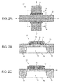
- Fig. 2A is a plan view of an ultrasonic transducer element 12 formed on a substrate (silicon substrate) 60 viewed from an element formation side in a direction perpendicular to a substrate 60.
- Fig. 2B is a cross-sectional view showing a cross-section along A-A' in Fig. 2A.
- Fig. 2C is a cross-sectional view showing a cross-section along B-B' in Fig. 2A .
- the ultrasonic transducer element 12 has a piezoelectric element part and a vibration film (membrane, supporting member) 50.
- the piezoelectric element part has a piezoelectric layer (piezoelectric film) 30, a first electrode layer (lower electrode) 31, and a second electrode layer (upper electrode) 32.
- the first electrode layer 31 is formed on an upper layer of the vibration film 50 with a metal thin film, for example.
- This first electrode layer 31 may be an interconnect that extends to outside the element formation area as shown in Fig. 2A , and is connected to an adjacent ultrasonic transducer element 12.
- the second electrode layer 32 is formed with a metal thin film, for example, and is provided so as to cover at least a portion of the piezoelectric layer 30.
- This second electrode layer 32 may be an interconnect that extends to outside the element formation area as shown in Fig. 2A , and is connected to an adjacent ultrasonic transducer element 12.
- the lower electrode (first electrode) of the ultrasonic transducer element 12 is formed by the first electrode layer 31, and the upper electrode (second electrode) is formed by the second electrode layer 32.
- the portion of the first electrode layer 31 covered by the piezoelectric layer 30 forms the lower electrode
- the portion of the second electrode layer 32 covering the piezoelectric layer 30 forms the upper electrode. That is, the piezoelectric layer 30 is provided so as to be sandwiched between the lower electrode and the upper electrode.
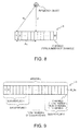
- Fig. 3 shows an exemplary configuration of the ultrasonic transducer device (element chip).
- the ultrasonic transducer device 11 of this exemplary configuration includes a plurality of ultrasonic transducer element groups UG1 to UG64 and drive electrode lines DL1 to DL64 (broadly, 1st to mth drive electrode lines, where m is an integer of 2 or more) and common electrode lines CL1 to CL8 (broadly, 1st to nth common electrode lines, where n is an integer of 2 or more).
- the number (m) of drive electrode lines and the number (n) of common electrode lines are not limited to the numbers shown in Fig. 3 .
- Fig. 4A shows an exemplary ultrasonic transducer element group UG (UG1 to UG64).
- the ultrasonic transducer element group UG is constituted by first to fourth element columns.
- the first element column is constituted by ultrasonic transducer elements UE11 to UE18 that are disposed in the first direction D1
- the second element column is constituted by ultrasonic transducer elements UE21 to UE28 that are disposed in the first direction D1.
- the third element column (UE31 to UE38) and the fourth element column (UE41 to UE48) are also similarly constituted.
- the drive electrode line DL (DL1 to DL64) is commonly connected to the first to fourth element columns.
- the common electrode lines CL1 to CL8 are connected to the ultrasonic transducer elements of the first to fourth element columns.
- the ultrasonic transducer element group UG in Fig. 4A constitutes one channel of the ultrasonic transducer device. That is, the drive electrode line DL is equivalent to the drive electrode line of one channel, and the transmission signal of one channel from a transmission circuit is input to the drive electrode line DL. Also, the reception signal of one channel constituted by the ultrasonic transducer element group UG is output from the drive electrode line DL. Note that the number of element columns constituting one channel is not limited to four columns as shown in Fig. 4A , and may be less than four columns or greater than four columns. For example, one channel may be constituted by a single element column, as shown in Fig. 4B .
- the drive electrode lines DL1 to DL64 (1st to mth drive electrode lines) are laid in the first direction D1.
- An ith drive electrode line DLi (ith channel) of the drive electrode lines DL1 to DL64 (where i is an integer such that 1 ⁇ i ⁇ m) is connected to the first electrode (e.g., lower electrode) of the ultrasonic transducer elements of the ith ultrasonic transducer element group UGi.
- Transmission signals VT1 to VT64 are supplied to the ultrasonic transducer elements UE via the drive electrode lines DL1 to DL64 in a transmission period for emitting ultrasonic waves. Also, reception signals VR1 to VR64 from the ultrasonic transducer elements UE are output via the drive electrode lines DL1 to DL64 in a reception period for receiving ultrasonic echo signals.
- the common electrode lines CL1 to CL8 (1st to nth common electrode lines) are laid in the second direction D2.
- the second electrode of the ultrasonic transducer elements is connected to one of the common electrode lines CL1 to CL8.
- a jth common electrode line CLj (where j is an integer such that 1 ⁇ j ⁇ n) of the common electrode lines CL1 to CL8 is connected to the second electrode (e.g., upper electrode) of the ultrasonic transducer elements that are disposed in the jth line.
- a common voltage V COM is supplied to the common electrode lines CL1 to CL8.
- This common voltage V COM need only be a constant direct current voltage, and not 0V, that is, not ground potential.
- a difference voltage between the transmission signal voltage and the common voltage is applied to the ultrasonic transducer elements, and ultrasonic waves of a predetermined frequency are emitted.
- the arrangement of the ultrasonic transducer elements is not limited to the matrix arrangement shown in Fig. 3 , and may be in a so-called houndstooth arrangement in which the elements of any two adjacent columns are disposed so as to zigzag alternately.
- Figs. 4A and 4B the case is shown where a single ultrasonic transducer element is used as both a transmission element and a reception element, but the present embodiment is not limited thereto.
- ultrasonic transducer elements for use as transmission elements and ultrasonic transducer elements for use as reception elements may be provided separately, and disposed in an array.
- the ultrasonic transducer elements 12 are not limited to a configuration that uses piezoelectric elements.
- transducers that use capacitive elements such as capacitive micro-machined ultrasonic transducers (cMUTs) may be employed, or bulk transducers may be employed.
- cMUTs capacitive micro-machined ultrasonic transducers
- the transmission processing unit 110 performs processing for transmitting ultrasonic waves toward the object.
- the transmission processing unit 110 has a transmission pulse generator 111 and a transmission delay circuit 113.
- the transmission pulse generator 111 applies a transmission pulse voltage to drive the ultrasonic probe 10.
- the transmission delay circuit 113 performs transmission focusing control, and causes the ultrasonic probe 10 to emit an ultrasonic beam corresponding to the generated pulse voltage toward the object.
- the transmission delay circuit 113 provides a time difference between channels with regard to the application timing of the transmission pulse voltage, and causes the ultrasonic waves produced by the plurality of vibration elements to converge. It is thus possible to arbitrarily change the focal length by changing the delay time.
- the full aperture 64 channels in the example shown in Fig. 3
- transmission and reception is performed with the resultant aperture (use aperture), with individual lines being generated while shifting the use aperture.
- the use apertures can be set to eight channels, for example. Note that beam width narrows and azimuth resolution increases with enlargement of the use aperture.
- the full aperture is used as the use aperture, and individual lines are generated while changing the beam direction.
- the transmission/reception changeover switch 140 performs changeover processing of ultrasonic wave transmission and reception.
- the transmission/reception changeover switch 140 protects the reception processing unit 120 from input of amplitude pulses at the time of transmission, and allows signals at the time of reception to pass through to the reception processing unit 120.
- the reception processing unit 120 performs processing for receiving reception waves of ultrasonic echoes relating to transmitted ultrasonic waves (hereinafter, reception waves).
- the reception processing unit 120 has a reception circuit 121, a filter circuit 123, and a memory 125.
- the reception circuit 121 converts the reception wave (analog signal) for each channel into a digital reception signal, and outputs the reception signal to the filter circuit 123. Note that focusing control of the reception waves is performed with the image processing unit 130 which will be discussed later.
- the memory 125 stores, for each channel, the reception signal for the channel output from the filter circuit 123.
- the functions of the memory 125 can be realized by using a storage device such as a random access memory (RAM).
- RAM random access memory
- Fig. 6 illustrates an exemplary structure of the data relating to each channel that is stored in the memory.
- the memory 125 stores, for each of the M channels, the transmission of one ultrasonic wave and the reception waves of ultrasonic echoes relating thereto as waveform data of N sample reception signals.
- M is the total number of channels of the use aperture and N is the total number of samplings.
- the total number of samplings is determined by, for example, a prescribed sampling frequency (e.g., 50 MHz) of the ultrasonic imaging apparatus 1, and the observation time for one reception wave.
- a prescribed sampling frequency e.g., 50 MHz
- the functions of the reception processing unit 120 can be realized by, for example, an analog front end (AFE) that is constituted by a low noise amplifier (LNA), a programmable gain amplifier (PGA), a filter circuit, an analog/digital converter (A/D convertor), and the like.
- AFE analog front end
- LNA low noise amplifier
- PGA programmable gain amplifier
- A/D convertor analog/digital converter
- the configuration of the reception processing unit 120 is not restricted to the illustrated example.
- the filter circuit 123 may be provided in the image processing unit 130 or upstream of an MVB processing unit 132, and filtering may be performed on the reception signal for each channel.
- the functions of a filtering circuit may be realized by software.
- the image processing unit 130 acquires the reception signals stored in the memory 125 of the reception processing unit 120, and performs various image processing.
- the image processing unit 130 has an error detection unit 131, the minimum variance beamforming (MVB) processing unit 132, a detection processing unit 133, a logarithmic transformation unit 135, a gain and dynamic range adjustment unit 137, and a sensitivity time control (STC) 139.
- MVB processing unit may also be referred to as a signal processing unit.
- the function relating to image generation among the functions of the image processing unit 130 may be referred to as an image generation unit.
- the error detection unit 131 performs error detection on each channel, based on the reception signal for the channel stored in the memory 125.
- the error detection unit 131 will be discussed in detail later.
- the detection processing unit 133 performs absolute value (rectification) processing on the reception signals that have undergone MVB processing or normal beamforming processing, and applies a low-pass filter to extract an unmodulated signal.
- the logarithmic transformation unit 135 performs Log compression on the extracted unmodulated signal, and converts the form of expression of the signal, so as to more easily confirm the maximum and minimum signal strengths of reception signals at the same time.
- the gain and dynamic range adjustment unit 137 adjusts the signal strength and the area of interest. For example, in gain adjustment processing, a direct current component is added to the Log-compressed input signal. Also, in dynamic range adjustment processing, the Log-compressed input signal is multiplied by an arbitrary number.
- the STC 139 corrects the degree of amplification (brightness) according to depth, and acquires an image having uniform brightness across the entire screen.
- the functions of the image processing unit 130 can be realized by hardware such as various processors (CPU, etc.), an ASIC (gate array, etc.) or the like, computer programs, or the like.
- the DSC 150 performs scan conversion on B-mode image data. For example, the DSC 150 converts line signals into image signals by interpolation processing such as bilinear interpolation. The DSC 150 then outputs the image signals to the display unit 21. Images are thereby displayed on the display unit 21.
- the control circuit 160 performs control of the transmission pulse generator 111, the transmission delay circuit 113, the transmission/reception changeover switch 140, the reception circuit 121, the memory 125, the MVB processing unit 131, and the like.
- the configuration of the ultrasonic imaging apparatus 1 is not limited to the above configuration.
- the instant invention is not restricted by the classification method or names of the constituent elements.
- the configuration of the ultrasonic imaging apparatus 1 can also be classified into more constituent elements according to the processing content.
- One constituent element can also be classified so as to execute more processing.
- the processing of each constituent element may be executed by one piece of hardware or may be executed by multiple pieces of hardware.
- Fig. 7 shows an exemplary hardware configuration for realizing the functions of the control unit.
- the control unit 22 can be realized by a computer that is provided with, for example, a central processing unit (CPU) 221 which is an arithmetic device, a random access memory (RAM) 222 which is a volatile storage device, a read only memory (ROM) 223 which is a nonvolatile storage device, a hard disk drive (HDD) 224, an interface (I/F) circuit 225 that connects the control unit 22 with other units, a communication apparatus 226 that performs communication with external devices, and a bus 227 that connects these constituent elements with each other.
- CPU central processing unit
- RAM random access memory
- ROM read only memory
- HDD hard disk drive
- I/F interface
- control unit 22 At least some of the above functions of the control unit 22 are realized by the CPU 221 reading out predetermined programs stored in the ROM 223 or the HDD 224 to the RAM 222 and executing the read programs.
- the predetermined programs may, for example, be installed in the ROM 223 or the HDD 224 in advance, or may be downloaded from a network via the communication apparatus 226 and installed or updated.
- the ultrasonic probe 10 is provided with an acoustic matching layer and an acoustic lens, in addition to the ultrasonic transducer device 11.
- an ultrasonic wave transmitted from the ultrasonic transducer device 11 is reflected by not only the object but also by members within the ultrasonic probe 10 such as the acoustic lens. That is, each channel of the ultrasonic transducer device 11 receives not only reflected waves from the object but also reflected wave from members such as the acoustic lens.
- the error detection unit 131 computes, for each channel, a total value S m of data for the period corresponding to the reflected wave from the acoustic lens by the following equation (1).
- the error detection unit 131 determines, on the basis of the average value of the total values S m of the channels, whether the total value S m of each channel is more than 2 ⁇ above the average value or more than 2 ⁇ below the average value, as shown in equation (3). If the total value S m is more than 2 ⁇ above or below the average value, the error detection unit 131 judges that the channel is an error channel.
- the error range is not limited to a range of 2 ⁇ , and may be set to another range such as 3 ⁇ . S m > S ⁇ + 2 ⁇ ⁇ or S m ⁇ S ⁇ - 2 ⁇ ⁇
- error judgment is based on a relative reference in the above method
- error judgment may be based on an absolute reference.
- the reflected intensity (reflectance) of the acoustic lens with respect to an ultrasonic wave can be derived in advance.
- the member of the ultrasonic probe 10 that is used is not limited to the acoustic lens.
- a configuration may also be adopted in which a predetermined value is set based on the reflected intensity of an object external to the ultrasonic probe 10, and an error channel is specified based on the reflected wave from the object.
- error channels are determined relatively using data for a period corresponding to the reflected wave from the acoustic lens
- the MVB processing unit 132 performs MVB processing, which is directionally-constrained adaptive beamforming.
- Adaptive beamforming is processing that involves dynamically changing the sensitivity characteristics so as to not have sensitivity to unwanted waves, by changing the weight of each channel according to the incoming wave. Even if an ultrasonic beam is transmitted so as to have high sound pressure in a frontal direction, ultrasonic waves also reach reflectors that exist in directions other than directly in front, since ultrasonic waves are characterized by spreading spherically. When unwanted waves reflected by reflectors other than the target are received, azimuth resolution deteriorates due to the influence of the unwanted waves. In contrast, adaptive beamforming places a constraint on direction so as to not have sensitivity to unwanted waves, thus enabling the problem of a decrease in azimuth resolution due to unwanted waves to be remedied.
- the reception focus processing unit 1321 provides a corresponding delay time D m determined in advance to the signal received by each normal channel so that the signals received by the respective normal channels are in phase. Since the reflected wave from a given reflector spreads spherically, a delay time is provided so that the arrival time at each vibrator is the same, and the reflected waves are added together taking into account the delay time.
- An output signal X m of the mth normal channel is derived with equation (4). Also, the output signal of each normal channel is given by equation (5) when expressed in vector notation.
- X m x m ⁇ n - D m n
- X n x 1 ⁇ n - D 1 n x 2 ⁇ n - D 2 n ⁇ x M _ fix ⁇ n - D M _ fix n
- the ultrasonic wave reflected from a reflection object (object) that is located in a depth direction Z from the ultrasonic transducer device 11 arrives at each channel as a spherical wave. Accordingly, the time taken for the reflection signal to arrive at the element of each channel is determined by a linear distance q m from the reflection object to the channel, with the ultrasonic wave taking longer to arrive as the distance of the element from the reflection object increases.
- An arrival time D' m for each element is geometrically derived as shown in equation (6), and is determined by a position p m of the ultrasonic transducer element 12 and a depth distance Z.
- c is the sound velocity (fixed value). Note that m is 1 to M in the description of the diagram.
- the output signal of each normal channel computed by the reception focus processing unit 1321 is output to the spatial averaging processing unit 1322.
- the spatial averaging processing unit 1322 extracts a plurality of sub apertures from the aperture constituted by the M_fix normal channels, and performs processing for taking respective averages thereof. Spatial averaging is performed in order to prevent azimuth estimation accuracy from deteriorating due to the influence of correlated interference waves when the value of each channel is used directly.
- the input vector of each sth sub aperture can be represented as shown in equation (7).
- x_fix s n x _ fix s ⁇ n - D s n x _ fix s + 1 ⁇ n - D s + 1 n ⁇ x _ fix s + S - 1 ⁇ n - D s n
- processing known as temporal averaging that takes the average in a time direction of each channel may be performed.
- Signals processed by the spatial averaging processing unit 1322 are output to the weight calculation unit 1323 or the weighted addition unit 1324.
- the spatial averaging processing unit 1322 is not an essential constituent element. In the case where spatial averaging is not performed, signals processed by the reception focus processing unit 1321 can be output to the weight calculation unit 1323 or the weighted addition unit 1324.
- the weight calculation unit 1323 computes the weight to be applied to the output of each normal channel. Here, weight calculation will be described.
- An output z that is output by the weighted addition unit 1324 is the result of multiplying a weight w m of each normal channel and a signal x_fix m obtained from delay processing performed on each channel that is output from the reception focus processing unit 1321 and summing the multiplication results, and is represented by equation (8).
- a is a steering vector.
- phasing has already being performed, so the direction is 0 degrees. Accordingly, a can be set to 1.
- the correlation matrix can be expressed as shown in equation (16).
- the weighted addition unit 1324 performs weighted addition, using the weight of each normal channel computed by the weight calculation unit 1323 and the reception signal of each normal channel computed by the spatial averaging processing unit 1322. That is, an operation using equation (18) is performed to obtain the output z.
- the signal obtained from the adding by the weighted addition unit 1324 is output to the detection processing unit 133.
- Figs. 10 to 13 are flowcharts (1 to 4) showing exemplary processing that is realized by the ultrasonic imaging apparatus. Note that the flowcharts of Figs. 10 to 13 show the flow for generating the image for one frame.
- the scan line number 1 is a number showing one of the ultrasonic transducer element groups UG1 to UG64 constituting an ultrasonic transducer device such as shown in Fig. 3 .
- the scan line number 1 of an element group provided at a given edge, here, the ultrasonic transducer element group UG1 is set to "1".
- the scan line number 1 of the element group that is adjacent to the element group having the scan line number "1", here, the ultrasonic transducer element group UG2, is set to "2".
- a scan line number 1 is thereby given to all the element groups.
- the relationship between the ultrasonic transducer element groups UG1 to UG64 and the scan line number 1 can be stored in a memory such as ROM.
- the control circuit 160 performs transmission and reception of an ultrasonic pulse having 0 degrees of phase at a frequency 1f, via all the channels of the use aperture corresponding to the scan line number 1 initialized at step S100 or the scan line number 1 updated at step S128 which will be discussed later (steps S101 to S106).
- the channels of the use aperture at the time of the scan line number "1" are the ultrasonic transducer element groups UG1 to UG8, and the channels of the use aperture at the time of the scan line number "2" are the ultrasonic transducer element groups UG2 to UG9.
- the relationship between scan line numbers and corresponding channels of the use aperture can be stored in a memory such as ROM.
- the transmission pulse generator 111 generates a pulse voltage for transmitting an ultrasonic pulse having 0 degrees of phase at a frequency 1f (step S101).
- the transmission delay circuit 113 performs transmission focusing control (step S102), and the ultrasonic probe 10 emits an ultrasonic beam corresponding to the pulse voltage generated at step S101 toward the object (step S103).
- the filter circuit 123 performs bandpass filtering on the reception signal for each channel of the use aperture (step S105).
- the control circuit 160 saves the reception signal each channel of the use aperture output from the filter circuit 123 to the memory 125 (step S106).
- the processing then advances to step S111 ( Fig. 11 ).
- control circuit 160 issues an instruction to the error detection unit 131, and the error detection unit 131, for each channel of the use aperture, acquires the reception signal saved in the memory 125 at step S106 and performs error detection based on the acquired reception signal (step S111).
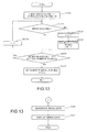
- the processing of step S111 will be described with reference to Fig. 12 .
- the error detection unit 131 set a counter i showing the channel number to be checked to 1, and sets a counter j showing the number of normal channels to 0 (step S1111). Note that the counter i shows each of the M channels of the use aperture corresponding to the scan line number 1.
- the error detection unit 131 determines whether the channel corresponding to the counter i initialized at step S1111 or the counter i updated at step S1116 which will be discussed later is in error (step S1112). The details of the error detection method are as described above.
- the error detection unit 131 When the channel i is not an error channel (NO at step S1112), the error detection unit 131 adds 1 to the counter j to update the counter j (step S1113). Also, the error detection unit 131 acquires data x i of the reception signal of the channel i, and stores the data x i as data x_fix j of the reception signal of a normal channel in a memory such as RAM (step S1114).
- step S1112 If the channel i is in error (YES at step S1112) or after step S1114, the error detection unit 131 judges whether the counter i showing the channel number to be checked is less than the total number M of channels (step S1115).
- step S1115 If the counter i is less than the total number M of channels (YES at step S1115), the error detection unit 131 adds 1 to the counter i to update the counter i(step S1116). The processing then returns to step S1112.
- the error detection unit 131 sets the number M_fix of normal channels to the value of the counter j (step S1117). The error detection unit 131 then advances the processing to step S112 ( Fig. 11 ).
- the MVB processing unit 132 performs MVB processing, which is directionally-constrained adaptive beamforming, based on the reception signal for each normal channel acquired at step S1114 ( Fig. 12 ) among all the channels of the use aperture (step S121).
- MVB processing which is directionally-constrained adaptive beamforming, based on the reception signal for each normal channel acquired at step S1114 ( Fig. 12 ) among all the channels of the use aperture (step S121).
- the details of this processing are as described above. That is, the reception focus processing unit 1321 performs predetermined delay processing, for each normal channel, on the reception signal of the normal channel, and the spatial averaging processing unit 1322 performs spatial averaging on the signals that have undergone delay processing by the reception focus processing unit 1321.
- the weight calculation unit 1323 then computes the weight for each normal channel, and the weighted addition unit 1324 performs weighted addition of the signal of the normal channel using the computed weight.
- the MVB processing unit 132 performs normal beamforming processing, based on the reception signals of all the channels of the use aperture (step S122). Specifically, the reception focus processing unit 1321 performs predetermined delay processing, for each channel, on the reception signal of the channel, and outputs the processed signals to the weighted addition unit 1324.
- the weighted addition unit 1324 performs weighted addition of the signal of each channel using a fixed weight defined in advance for the channel.
- the detection processing unit 133 performs envelope detection, which involves applying a low-pass filter to the output signal for the scan line number 1 output by the MVB processing unit 132 at step S121 or step S122, after absolute value (rectification) processing has been performed thereon, and extracting an unmodulated signal (step S123). Then, the logarithmic transformation unit 135 performs logarithmic transformation (step S124).
- the gain and dynamic range adjustment unit 137 adjusts the signal strength and the area of interest (step S125). Then, the STC 139 corrects the degree of amplification (brightness) according to depth (step S126).
- the control circuit 160 judges whether the scan line number 1, which indicates the line for generating an image, is less than the number L of scan lines (step S127).
- the number L of scan lines in the case of an ultrasonic transducer device such as shown in Fig. 3 , depends on the number of ultrasonic transducer element groups UG1 to UG64.
- the control circuit 160 issues an instruction to the image processing unit 130, and the image processing unit 130 generates a frame image from the signals of all the scan lines processed at steps S121 to S126, and advances the processing to step S131 ( Fig. 13 ).
- error channels are detected and adaptive beamforming is executed on the reception signals of normal channels other than the error channels.
- the influence of the reception signals of channels that cannot receive signals correctly is thereby avoided, and the likelihood of a decrease in the effects of adaptive beamforming (high azimuth resolution, etc.) can be reduced.
- error channel detection is performed when generating the image for one line. Faults or the like that occurs due to aged deterioration of the elements or the like can thereby be accurately detected. Also, since adaptive beamforming is performed on the reception signals of normal channels for each line, the likelihood of a decrease in the effects of adaptive beamforming can be reduced.
- error channels are detected relatively, using the values of the reception signals of a plurality of channels. Error channels can thereby be accurately detected, even when aged deterioration or the like occurs in all the channels.
- error channel detection is performed using the reflected wave of a specific member provided in the probe such as the acoustic lens. Error channels can thereby be accurately detected, without being affected by the external environment or the like.
- normal beamforming is performed instead of adaptive beamforming, in the case where there are more than a predetermined number of error channels. Resolution can thereby be improved by executing normal beamforming, in the case where resolution would conversely decrease if adaptive beamforming were executed.
- the invention is not limited to an ultrasonic imaging apparatus, and can also be provided in various forms, such as an image processing method that is performed in an ultrasonic imaging apparatus, a program of an ultrasonic imaging apparatus, or a storage medium on which the program is stored.
- the invention can also be provided as an ultrasonic measurement apparatus in which the ultrasonic measurement apparatus main unit does not have the display unit 21, and generated image data for display is output to an external display unit.
- the invention can be applied with regard to any scanning method, such as linear scanning for dividing the aperture of the probe and generating lines using sub apertures, sector scanning for angling the ultrasonic beam by adjusting the delay time of each channel, and offset sector scanning for use in a convex probe. Also, the invention can even be applied with regard a scanning method in which transmission and reception are not performed every line, such as the synthetic aperture method.
Landscapes
- Engineering & Computer Science (AREA)
- Physics & Mathematics (AREA)
- Radar, Positioning & Navigation (AREA)
- Remote Sensing (AREA)
- Acoustics & Sound (AREA)
- Computer Networks & Wireless Communication (AREA)
- General Physics & Mathematics (AREA)
- Health & Medical Sciences (AREA)
- Life Sciences & Earth Sciences (AREA)
- Pathology (AREA)
- Surgery (AREA)
- Nuclear Medicine, Radiotherapy & Molecular Imaging (AREA)
- Gynecology & Obstetrics (AREA)
- Radiology & Medical Imaging (AREA)
- Biomedical Technology (AREA)
- Heart & Thoracic Surgery (AREA)
- Medical Informatics (AREA)
- Molecular Biology (AREA)
- Biophysics (AREA)
- Animal Behavior & Ethology (AREA)
- General Health & Medical Sciences (AREA)
- Public Health (AREA)
- Veterinary Medicine (AREA)
- Ultra Sonic Daignosis Equipment (AREA)
- Investigating Or Analyzing Materials By The Use Of Ultrasonic Waves (AREA)
- Measurement Of Velocity Or Position Using Acoustic Or Ultrasonic Waves (AREA)
Applications Claiming Priority (1)
| Application Number | Priority Date | Filing Date | Title |
|---|---|---|---|
| JP2013187153A JP6331297B2 (ja) | 2013-09-10 | 2013-09-10 | 超音波測定装置、超音波画像装置、及び超音波測定方法 |
Publications (1)
| Publication Number | Publication Date |
|---|---|
| EP2846170A1 true EP2846170A1 (en) | 2015-03-11 |
Family
ID=51492219
Family Applications (1)
| Application Number | Title | Priority Date | Filing Date |
|---|---|---|---|
| EP14183898.7A Withdrawn EP2846170A1 (en) | 2013-09-10 | 2014-09-08 | Ultrasonic measurement apparatus, ultrasonic imaging apparatus, and ultrasonic measurement method |
Country Status (4)
| Country | Link |
|---|---|
| US (1) | US20150071030A1 (enExample) |
| EP (1) | EP2846170A1 (enExample) |
| JP (1) | JP6331297B2 (enExample) |
| CN (1) | CN104422931B (enExample) |
Cited By (1)
| Publication number | Priority date | Publication date | Assignee | Title |
|---|---|---|---|---|
| US10682671B2 (en) * | 2015-01-21 | 2020-06-16 | Samsung Electronics Co., Ltd. | Ultrasonic imaging apparatus, ultrasonic probe apparatus, signal processing apparatus and method of controlling ultrasonic imaging apparatus |
Families Citing this family (10)
| Publication number | Priority date | Publication date | Assignee | Title |
|---|---|---|---|---|
| JP2015112326A (ja) * | 2013-12-12 | 2015-06-22 | キヤノン株式会社 | プローブ、被検体情報取得装置 |
| JP6584839B2 (ja) * | 2015-06-30 | 2019-10-02 | キヤノンメディカルシステムズ株式会社 | 体外式超音波プローブ |
| KR102569445B1 (ko) | 2015-12-04 | 2023-08-24 | 삼성메디슨 주식회사 | 초음파 프로브의 채널의 전기적 이상 여부를 판단하는 방법 및 장치. |
| CN105631824B (zh) * | 2015-12-25 | 2019-06-18 | 中国科学院深圳先进技术研究院 | 一种探测器晶体阵列分辨图处理方法和装置 |
| JP6772708B2 (ja) * | 2016-09-16 | 2020-10-21 | コニカミノルタ株式会社 | 超音波プローブおよび当該超音波プローブの補正方法 |
| US10797221B2 (en) * | 2017-02-24 | 2020-10-06 | Baker Hughes, A Ge Company, Llc | Method for manufacturing an assembly for an ultrasonic probe |
| JP6954826B2 (ja) | 2017-12-20 | 2021-10-27 | オリンパス株式会社 | 超音波観測装置、超音波観測装置の作動方法および超音波観測装置の作動プログラム |
| JP7081143B2 (ja) * | 2017-12-27 | 2022-06-07 | セイコーエプソン株式会社 | 超音波装置、及び超音波測定方法 |
| KR20210076730A (ko) | 2019-12-16 | 2021-06-24 | 삼성메디슨 주식회사 | 초음파 진단 장치 및 초음파 진단 장치의 제어방법 |
| JP2024068538A (ja) * | 2022-11-08 | 2024-05-20 | キヤノンメディカルシステムズ株式会社 | 超音波受信装置、及び超音波受信方法 |
Citations (4)
| Publication number | Priority date | Publication date | Assignee | Title |
|---|---|---|---|---|
| EP0713102A1 (en) * | 1994-11-16 | 1996-05-22 | Advanced Technology Laboratories, Inc. | Self diagnostic ultrasonic imaging systems |
| JP2012005789A (ja) * | 2010-06-28 | 2012-01-12 | Toshiba Corp | 超音波診断装置 |
| JP2012170826A (ja) | 2011-02-21 | 2012-09-10 | Samsung Electronics Co Ltd | 超音波ビーム形成方法及びその装置と超音波画像システム並びにコンピュータで読み取り可能な記録媒体 |
| US20130194891A1 (en) * | 2012-01-31 | 2013-08-01 | General Electric Company | Method and system for monitoring a transducer array in an ultrasound system |
Family Cites Families (3)
| Publication number | Priority date | Publication date | Assignee | Title |
|---|---|---|---|---|
| EP2019625B1 (en) * | 2006-05-12 | 2016-06-08 | Koninklijke Philips N.V. | Ultrasonic synthetic transmit focusing with motion compensation |
| CN100589761C (zh) * | 2008-02-01 | 2010-02-17 | 哈尔滨工业大学 | 基于相关性分析的超声成像系统自适应波束形成器及其形成方法 |
| KR101797038B1 (ko) * | 2011-04-22 | 2017-11-13 | 삼성전자주식회사 | 진단영상을 생성하는 방법, 이를 수행하는 장치, 진단시스템 및 의료영상시스템 |
-
2013
- 2013-09-10 JP JP2013187153A patent/JP6331297B2/ja active Active
-
2014
- 2014-08-27 US US14/470,508 patent/US20150071030A1/en not_active Abandoned
- 2014-09-04 CN CN201410449672.0A patent/CN104422931B/zh active Active
- 2014-09-08 EP EP14183898.7A patent/EP2846170A1/en not_active Withdrawn
Patent Citations (4)
| Publication number | Priority date | Publication date | Assignee | Title |
|---|---|---|---|---|
| EP0713102A1 (en) * | 1994-11-16 | 1996-05-22 | Advanced Technology Laboratories, Inc. | Self diagnostic ultrasonic imaging systems |
| JP2012005789A (ja) * | 2010-06-28 | 2012-01-12 | Toshiba Corp | 超音波診断装置 |
| JP2012170826A (ja) | 2011-02-21 | 2012-09-10 | Samsung Electronics Co Ltd | 超音波ビーム形成方法及びその装置と超音波画像システム並びにコンピュータで読み取り可能な記録媒体 |
| US20130194891A1 (en) * | 2012-01-31 | 2013-08-01 | General Electric Company | Method and system for monitoring a transducer array in an ultrasound system |
Non-Patent Citations (2)
| Title |
|---|
| JAMES S HALL ET AL: "Minimum variance ultrasonic imaging applied to an in situ sparse guided wave array", IEEE TRANSACTIONS ON ULTRASONICS, FERROELECTRICS AND FREQUENCY CONTROL, vol. 57, no. 10, 1 October 2010 (2010-10-01), pages 2311 - 2323, XP011319234, ISSN: 0885-3010 * |
| J-F SYNNEVAG ET AL: "Adaptive Beamforming Applied to Medical Ultrasound Imaging", IEEE TRANSACTIONS ON ULTRASONICS, FERROELECTRICS AND FREQUENCY CONTROL, IEEE, US, vol. 54, no. 8, 1 August 2007 (2007-08-01), pages 1606 - 1613, XP011190325, ISSN: 0885-3010, DOI: 10.1109/TUFFC.2007.431 * |
Cited By (1)
| Publication number | Priority date | Publication date | Assignee | Title |
|---|---|---|---|---|
| US10682671B2 (en) * | 2015-01-21 | 2020-06-16 | Samsung Electronics Co., Ltd. | Ultrasonic imaging apparatus, ultrasonic probe apparatus, signal processing apparatus and method of controlling ultrasonic imaging apparatus |
Also Published As
| Publication number | Publication date |
|---|---|
| CN104422931B (zh) | 2019-03-08 |
| US20150071030A1 (en) | 2015-03-12 |
| JP6331297B2 (ja) | 2018-05-30 |
| CN104422931A (zh) | 2015-03-18 |
| JP2015053961A (ja) | 2015-03-23 |
Similar Documents
| Publication | Publication Date | Title |
|---|---|---|
| EP2846170A1 (en) | Ultrasonic measurement apparatus, ultrasonic imaging apparatus, and ultrasonic measurement method | |
| CN110063749B (zh) | 超声波测定装置、超声波图像装置及超声波测定方法 | |
| JP5575554B2 (ja) | 超音波診断装置 | |
| US9910140B2 (en) | Ultrasonic measurement apparatus, ultrasonic imaging apparatus, and ultrasonic measurement method | |
| US5487306A (en) | Phase aberration correction in phased-array imaging systems | |
| US20150366542A1 (en) | Ultrasound imaging system using beamforming techniques for phase coherence grating lobe suppression | |
| US5460180A (en) | Connection arrangement and method of operation of a 2D array for phase aberration correction | |
| US9465009B2 (en) | Ultrasonic measuring device, ultrasonic image device, and method for processing ultrasonic image | |
| JP2018531727A (ja) | 干渉分析器を含むボリューム領域の超音波画像を可変周波数で提供するための超音波システム | |
| US10031226B2 (en) | Ultrasonic measurement apparatus, ultrasonic diagnostic apparatus, and ultrasonic measurement method | |
| US20150063057A1 (en) | Ultrasonic measurement apparatus, ultrasonic imaging apparatus, and ultrasonic measurement method | |
| US10197670B2 (en) | Ultrasonic measurement apparatus, ultrasonic diagnostic apparatus, and ultrasonic measurement method | |
| EP2944976B1 (en) | Beam forming apparatus, method for forming beams, ultrasonic imaging apparatus, and ultrasonic probe | |
| US10682671B2 (en) | Ultrasonic imaging apparatus, ultrasonic probe apparatus, signal processing apparatus and method of controlling ultrasonic imaging apparatus | |
| US10849598B2 (en) | Ultrasonic measurement apparatus, ultrasonic imaging apparatus, and ultrasonic measurement method | |
| US10054677B2 (en) | Beamforming apparatus, beamforming method, and ultrasonic imaging apparatus | |
| US5517995A (en) | 2D array for phase aberration correction | |
| US20070167786A1 (en) | Fresnel zone imaging system and method | |
| Bruno et al. | Beamforming with AlN-based bimorph piezoelectric micromachined ultrasonic transducers | |
| JP6237007B2 (ja) | 超音波測定装置、超音波画像装置及び超音波測定方法 | |
| JP7211150B2 (ja) | 超音波診断装置、超音波画像生成方法及びプログラム | |
| JP6089741B2 (ja) | 超音波測定装置、超音波画像装置及び超音波測定方法 | |
| JP6186737B2 (ja) | 超音波測定装置、超音波画像装置及び超音波測定方法 | |
| JP2013165882A (ja) | 被検体情報取得装置およびその制御方法 |
Legal Events
| Date | Code | Title | Description |
|---|---|---|---|
| 17P | Request for examination filed |
Effective date: 20140908 |
|
| AK | Designated contracting states |
Kind code of ref document: A1 Designated state(s): AL AT BE BG CH CY CZ DE DK EE ES FI FR GB GR HR HU IE IS IT LI LT LU LV MC MK MT NL NO PL PT RO RS SE SI SK SM TR |
|
| AX | Request for extension of the european patent |
Extension state: BA ME |
|
| PUAI | Public reference made under article 153(3) epc to a published international application that has entered the european phase |
Free format text: ORIGINAL CODE: 0009012 |
|
| R17P | Request for examination filed (corrected) |
Effective date: 20150827 |
|
| RBV | Designated contracting states (corrected) |
Designated state(s): AL AT BE BG CH CY CZ DE DK EE ES FI FR GB GR HR HU IE IS IT LI LT LU LV MC MK MT NL NO PL PT RO RS SE SI SK SM TR |
|
| 17Q | First examination report despatched |
Effective date: 20170602 |
|
| GRAP | Despatch of communication of intention to grant a patent |
Free format text: ORIGINAL CODE: EPIDOSNIGR1 |
|
| RIC1 | Information provided on ipc code assigned before grant |
Ipc: G01S 15/89 20060101ALI20181018BHEP Ipc: A61B 8/00 20060101ALI20181018BHEP Ipc: G01S 7/52 20060101AFI20181018BHEP |
|
| INTG | Intention to grant announced |
Effective date: 20181116 |
|
| RAP1 | Party data changed (applicant data changed or rights of an application transferred) |
Owner name: SEIKO EPSON CORPORATION |
|
| RIN1 | Information on inventor provided before grant (corrected) |
Inventor name: HAYASHI, MASAKI |
|
| STAA | Information on the status of an ep patent application or granted ep patent |
Free format text: STATUS: THE APPLICATION IS DEEMED TO BE WITHDRAWN |
|
| 18D | Application deemed to be withdrawn |
Effective date: 20190327 |