EP2846065B1 - Automatic transmission - Google Patents
Automatic transmission Download PDFInfo
- Publication number
- EP2846065B1 EP2846065B1 EP13881990.9A EP13881990A EP2846065B1 EP 2846065 B1 EP2846065 B1 EP 2846065B1 EP 13881990 A EP13881990 A EP 13881990A EP 2846065 B1 EP2846065 B1 EP 2846065B1
- Authority
- EP
- European Patent Office
- Prior art keywords
- clutch
- block
- rotated
- needle
- hub housing
- Prior art date
- Legal status (The legal status is an assumption and is not a legal conclusion. Google has not performed a legal analysis and makes no representation as to the accuracy of the status listed.)
- Active
Links
Images






Classifications
-
- F—MECHANICAL ENGINEERING; LIGHTING; HEATING; WEAPONS; BLASTING
- F16—ENGINEERING ELEMENTS AND UNITS; GENERAL MEASURES FOR PRODUCING AND MAINTAINING EFFECTIVE FUNCTIONING OF MACHINES OR INSTALLATIONS; THERMAL INSULATION IN GENERAL
- F16D—COUPLINGS FOR TRANSMITTING ROTATION; CLUTCHES; BRAKES
- F16D41/00—Freewheels or freewheel clutches
- F16D41/06—Freewheels or freewheel clutches with intermediate wedging coupling members between an inner and an outer surface
- F16D41/064—Freewheels or freewheel clutches with intermediate wedging coupling members between an inner and an outer surface the intermediate members wedging by rolling and having a circular cross-section, e.g. balls
- F16D41/066—Freewheels or freewheel clutches with intermediate wedging coupling members between an inner and an outer surface the intermediate members wedging by rolling and having a circular cross-section, e.g. balls all members having the same size and only one of the two surfaces being cylindrical
- F16D41/067—Freewheels or freewheel clutches with intermediate wedging coupling members between an inner and an outer surface the intermediate members wedging by rolling and having a circular cross-section, e.g. balls all members having the same size and only one of the two surfaces being cylindrical and the members being distributed by a separate cage encircling the axis of rotation
-
- F—MECHANICAL ENGINEERING; LIGHTING; HEATING; WEAPONS; BLASTING
- F16—ENGINEERING ELEMENTS AND UNITS; GENERAL MEASURES FOR PRODUCING AND MAINTAINING EFFECTIVE FUNCTIONING OF MACHINES OR INSTALLATIONS; THERMAL INSULATION IN GENERAL
- F16H—GEARING
- F16H3/00—Toothed gearings for conveying rotary motion with variable gear ratio or for reversing rotary motion
- F16H3/003—Toothed gearings for conveying rotary motion with variable gear ratio or for reversing rotary motion the gear ratio being changed by inversion of torque direction
- F16H3/005—Toothed gearings for conveying rotary motion with variable gear ratio or for reversing rotary motion the gear ratio being changed by inversion of torque direction for gearings using gears having orbital motion
-
- F—MECHANICAL ENGINEERING; LIGHTING; HEATING; WEAPONS; BLASTING
- F16—ENGINEERING ELEMENTS AND UNITS; GENERAL MEASURES FOR PRODUCING AND MAINTAINING EFFECTIVE FUNCTIONING OF MACHINES OR INSTALLATIONS; THERMAL INSULATION IN GENERAL
- F16H—GEARING
- F16H3/00—Toothed gearings for conveying rotary motion with variable gear ratio or for reversing rotary motion
- F16H3/44—Toothed gearings for conveying rotary motion with variable gear ratio or for reversing rotary motion using gears having orbital motion
- F16H3/46—Gearings having only two central gears, connected by orbital gears
-
- F—MECHANICAL ENGINEERING; LIGHTING; HEATING; WEAPONS; BLASTING
- F16—ENGINEERING ELEMENTS AND UNITS; GENERAL MEASURES FOR PRODUCING AND MAINTAINING EFFECTIVE FUNCTIONING OF MACHINES OR INSTALLATIONS; THERMAL INSULATION IN GENERAL
- F16D—COUPLINGS FOR TRANSMITTING ROTATION; CLUTCHES; BRAKES
- F16D41/00—Freewheels or freewheel clutches
- F16D41/04—Freewheels or freewheel clutches combined with a clutch for locking the driving and driven members
-
- F—MECHANICAL ENGINEERING; LIGHTING; HEATING; WEAPONS; BLASTING
- F16—ENGINEERING ELEMENTS AND UNITS; GENERAL MEASURES FOR PRODUCING AND MAINTAINING EFFECTIVE FUNCTIONING OF MACHINES OR INSTALLATIONS; THERMAL INSULATION IN GENERAL
- F16D—COUPLINGS FOR TRANSMITTING ROTATION; CLUTCHES; BRAKES
- F16D41/00—Freewheels or freewheel clutches
- F16D41/06—Freewheels or freewheel clutches with intermediate wedging coupling members between an inner and an outer surface
-
- F—MECHANICAL ENGINEERING; LIGHTING; HEATING; WEAPONS; BLASTING
- F16—ENGINEERING ELEMENTS AND UNITS; GENERAL MEASURES FOR PRODUCING AND MAINTAINING EFFECTIVE FUNCTIONING OF MACHINES OR INSTALLATIONS; THERMAL INSULATION IN GENERAL
- F16D—COUPLINGS FOR TRANSMITTING ROTATION; CLUTCHES; BRAKES
- F16D41/00—Freewheels or freewheel clutches
- F16D41/06—Freewheels or freewheel clutches with intermediate wedging coupling members between an inner and an outer surface
- F16D41/064—Freewheels or freewheel clutches with intermediate wedging coupling members between an inner and an outer surface the intermediate members wedging by rolling and having a circular cross-section, e.g. balls
-
- F—MECHANICAL ENGINEERING; LIGHTING; HEATING; WEAPONS; BLASTING
- F16—ENGINEERING ELEMENTS AND UNITS; GENERAL MEASURES FOR PRODUCING AND MAINTAINING EFFECTIVE FUNCTIONING OF MACHINES OR INSTALLATIONS; THERMAL INSULATION IN GENERAL
- F16D—COUPLINGS FOR TRANSMITTING ROTATION; CLUTCHES; BRAKES
- F16D41/00—Freewheels or freewheel clutches
- F16D41/06—Freewheels or freewheel clutches with intermediate wedging coupling members between an inner and an outer surface
- F16D41/064—Freewheels or freewheel clutches with intermediate wedging coupling members between an inner and an outer surface the intermediate members wedging by rolling and having a circular cross-section, e.g. balls
- F16D41/066—Freewheels or freewheel clutches with intermediate wedging coupling members between an inner and an outer surface the intermediate members wedging by rolling and having a circular cross-section, e.g. balls all members having the same size and only one of the two surfaces being cylindrical
-
- F—MECHANICAL ENGINEERING; LIGHTING; HEATING; WEAPONS; BLASTING
- F16—ENGINEERING ELEMENTS AND UNITS; GENERAL MEASURES FOR PRODUCING AND MAINTAINING EFFECTIVE FUNCTIONING OF MACHINES OR INSTALLATIONS; THERMAL INSULATION IN GENERAL
- F16D—COUPLINGS FOR TRANSMITTING ROTATION; CLUTCHES; BRAKES
- F16D41/00—Freewheels or freewheel clutches
- F16D41/06—Freewheels or freewheel clutches with intermediate wedging coupling members between an inner and an outer surface
- F16D41/069—Freewheels or freewheel clutches with intermediate wedging coupling members between an inner and an outer surface the intermediate members wedging by pivoting or rocking, e.g. sprags
- F16D41/07—Freewheels or freewheel clutches with intermediate wedging coupling members between an inner and an outer surface the intermediate members wedging by pivoting or rocking, e.g. sprags between two cylindrical surfaces
-
- F—MECHANICAL ENGINEERING; LIGHTING; HEATING; WEAPONS; BLASTING
- F16—ENGINEERING ELEMENTS AND UNITS; GENERAL MEASURES FOR PRODUCING AND MAINTAINING EFFECTIVE FUNCTIONING OF MACHINES OR INSTALLATIONS; THERMAL INSULATION IN GENERAL
- F16H—GEARING
- F16H3/00—Toothed gearings for conveying rotary motion with variable gear ratio or for reversing rotary motion
- F16H3/44—Toothed gearings for conveying rotary motion with variable gear ratio or for reversing rotary motion using gears having orbital motion
-
- F—MECHANICAL ENGINEERING; LIGHTING; HEATING; WEAPONS; BLASTING
- F16—ENGINEERING ELEMENTS AND UNITS; GENERAL MEASURES FOR PRODUCING AND MAINTAINING EFFECTIVE FUNCTIONING OF MACHINES OR INSTALLATIONS; THERMAL INSULATION IN GENERAL
- F16D—COUPLINGS FOR TRANSMITTING ROTATION; CLUTCHES; BRAKES
- F16D41/00—Freewheels or freewheel clutches
- F16D41/06—Freewheels or freewheel clutches with intermediate wedging coupling members between an inner and an outer surface
- F16D41/064—Freewheels or freewheel clutches with intermediate wedging coupling members between an inner and an outer surface the intermediate members wedging by rolling and having a circular cross-section, e.g. balls
- F16D2041/0646—Freewheels or freewheel clutches with intermediate wedging coupling members between an inner and an outer surface the intermediate members wedging by rolling and having a circular cross-section, e.g. balls the intermediate coupling members moving between recesses in an inner race and recesses in an outer race
-
- F—MECHANICAL ENGINEERING; LIGHTING; HEATING; WEAPONS; BLASTING
- F16—ENGINEERING ELEMENTS AND UNITS; GENERAL MEASURES FOR PRODUCING AND MAINTAINING EFFECTIVE FUNCTIONING OF MACHINES OR INSTALLATIONS; THERMAL INSULATION IN GENERAL
- F16H—GEARING
- F16H2200/00—Transmissions for multiple ratios
- F16H2200/20—Transmissions using gears with orbital motion
- F16H2200/203—Transmissions using gears with orbital motion characterised by the engaging friction means not of the freewheel type, e.g. friction clutches or brakes
- F16H2200/2069—Transmissions using gears with orbital motion characterised by the engaging friction means not of the freewheel type, e.g. friction clutches or brakes using two freewheel mechanism
-
- F—MECHANICAL ENGINEERING; LIGHTING; HEATING; WEAPONS; BLASTING
- F16—ENGINEERING ELEMENTS AND UNITS; GENERAL MEASURES FOR PRODUCING AND MAINTAINING EFFECTIVE FUNCTIONING OF MACHINES OR INSTALLATIONS; THERMAL INSULATION IN GENERAL
- F16H—GEARING
- F16H2200/00—Transmissions for multiple ratios
- F16H2200/20—Transmissions using gears with orbital motion
- F16H2200/2079—Transmissions using gears with orbital motion using freewheel type mechanisms, e.g. freewheel clutches
- F16H2200/2084—Transmissions using gears with orbital motion using freewheel type mechanisms, e.g. freewheel clutches two freewheel mechanisms
Definitions
- This invention relates to an automatic transmission, and more particularly, to an automatic transmission that is capable of changing speed and moving forward or backward without using an additional device.
- a planetary gearbox is a combination of gears in a state in which sun gears, ring gears and planetary gears are disposed in a concentric line.
- the planetary gearbox has a small volume, a concentric input/output and high power transmission efficiency compared to a gear train disposed in a gearbox that operates based on a different principle and thus is widely used in the field in which small size and lightweight are required.
- Korean Patent Application No. 10-2005-0132839 discloses a self centering type assembling device for a planetary reduction gear so as to obtain a large gear ratio by applying the planetary gear.
- Korean Patent No. 1,190,755 discloses a star type forward reverse one way transmission.
- a forward rotational force transferred through a power transmission unit is transferred to a main carrier using a forward ratchet so that the forward rotational force can be output in a forward direction.
- a reverse rotational force transferred through the power transmission unit is transferred to an internal carrier using a reverse ratchet, and a large output in the forward direction can be obtained while the speed of the carrier is reduced, using a sun gear and a planetary gear engaged with the other side of the internal carrier and a ring gear of an external carrier.
- Korean Patent No. 1,190,755 that is the related art has a critical problem that the main carrier cannot move backward.
- a problem to be solved by the present invention is providing an automatic transmission in which a hub housing may be rotated both, in a forward as well as in a reverse direction when it is driven from the output side, wherein the transmission ratio is 1:1 when the input shaft is driven from the input side in the forward direction, and the transmission ratio is different from 1:1 when the input shaft is driven from the input side in the reverse direction.
- the present invention has the following effects.
- a hub housing can be rotated in a reverse direction so that an automatic transmission according to the present invention can move backward.
- the automatic transmission can perform transmission and move forward or backward without using an additional device.
- the hub housing can be output in the forward direction at a constant gear ratio when an input shaft is rotated in a forward direction, and the hub housing can be output in the forward direction at a large gear ratio when the input shaft is rotated in the reverse direction.
- a second clutch may include several sub-clutches so that a clutch suitable for environment can be selected.
- a first clutch may include a first needle clutch or a first buffering clutch so that component replacement and manufacturing can be very easily performed.
- a second sub-clutch may include one of a needle clutch, a buffering clutch and a one way clutch so that component replacement and manufacturing can be very easily performed.
- a locking gap of the first clutch is formed to be greater than a locking gap of the second clutch, the second clutch gets loose prior to the first clutch when the hub housing is rotated in the reverse direction so that locking is released and the automatic transmission can easily move backward.
- a concentric block with a gap is installed so that a moving-backward operation of the hub housing can be smoothly performed when the hub housing is rotated in the reverse direction.
- the locking gap of the first clutch and a locking gap of the second buffering clutch, a second needle clutch or a one way clutch are formed to be greater than the locking gap of the second sub-clutch so that the second sub-clutch linked to a third sub-clutch is unlocked prior to the first clutch when the hub housing is reversely rotated and thus the moving-backward operation of the hub housing can be smoothly performed when the hub housing is rotated in the reverse direction.
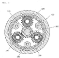
- FIG. 1 is a cross-sectional view of an automatic transmission according to a first exemplary embodiment of the present invention
- FIG. 2 is a cross-sectional view of an automatic transmission according to a second exemplary embodiment of the present invention
- FIG. 3 is a cross-sectional view of an automatic transmission according to a third exemplary embodiment of the present invention.
- a clockwise direction is defined as a forward direction and a counterclockwise direction is defined as a reverse direction based on the drawings and it will be described.
- the present invention includes a first clutch and a second clutch.
- the first clutch includes a first needle clutch illustrated in FIG. 6 and a first buffering clutch illustrated in FIG. 7 .
- the second clutch includes a first sub-clutch , a second sub-clutch , and a third sub-clutch .
- a locking gap of the second sub-clutch may be preferably formed to be smaller than a locking gap of the first clutch and a locking gap of the first sub-clutch .
- the first sub-clutch may be connected to an opposite side to a satellite gear 320 installed at a planetary gear portion and may confine a carrier 340 to be rotated in the reverse direction.
- the second sub-clutch may be connected to the first sub-clutch .
- One side of the third sub-clutch may be connected to a hub housing 400, and the other side of the third sub-clutch may be connected to the second sub-clutch so that the third sub-clutch may confine reverse rotation of the hub housing 400.
- the first sub-clutch includes one of a second needle clutch that is illustrated in FIG. 9 , a second buffering clutch illustrated in FIG. 10 , and a one way clutch illustrated in FIG. 11 , which will be described later.
- An input shaft 160 is inserted into a fixing shaft 500 and is rotatably installed thereon.
- the input shaft 160 is installed at the left side of the automatic transmission, i.e., at a first bearing 610 so as to be smoothly rotated on the fixing shaft 500, and a first sealing portion 710 is installed at the left side of the first bearing 610, i.e., between the fixing shaft 500 and the input shaft 160 and keeps an air-tight state of the fixing shaft 500 and the input shaft 160.
- a driving force transferring unit such as a belt or chain, may be hung on one side of the input shaft 160, and a sun gear 310 is formed on a right outer circumferential surface of the input shaft 160.
- a part of the input shaft 160 is inserted into the hub housing 400.
- a second sealing portion 720 is installed between a left outer circumferential surface of the input shaft 160 and a left inner circumferential surface of the hub housing 400 and keeps an air-tight state of the input shaft 160 and the hub housing 400.
- the second bearing 620 is installed at a right side of the second sealing portion 720, i.e., between the hub housing 400 and the input shaft 160.
- a first needle block 172 is fixed to the input shaft 160.
- a first clutch block 110 is fitted onto the first needle block 172 and is connected to the hub housing 400.
- a first retainer 170 is installed between the first needle block 172 and the first clutch block 110.
- a plurality of first needle pins 171 are installed in the first retainer 170.
- the first needle clutch includes the first needle block 172 and the first clutch block 110, the first retainer 170, and the first needle pin 171.
- FIG. 4 is a cross-sectional view of a first needle clutch taken along line A-A according to first, fifth, and sixth exemplary embodiments of the present invention.
- the first needle block 172 Since the first needle block 172 is fitted onto an outer surface of the input shaft 160 and is fixed to the input shaft 160, the first needle block 172 is rotated together with the input shaft 160.
- the first clutch block 110 is connected to an inner circumferential surface of the hub housing 400 and is rotated together with the hub housing 400.
- the first retainer 170 includes a plurality of first needle pins 171 and is installed between the first needle block 172 and the first clutch block 110.
- a first groove 173 is formed in an outer circumferential surface of the first needle block 172 so that the first groove 173 is formed to be close to the first retainer 170.
- a second groove 174 slantly extends from the first groove 173, and a third groove 175 extends from the second groove 174, and the first needle pin 171 is accommodated in the third groove 175.
- the third groove 175 is formed to be concave in a direction of a center of rotation of the first clutch block 110, when the first needle pin 171 is placed in the third groove 175, the first needle pin 171 may freely move between the first clutch block 110 and the first needle block 172.
- the first groove 173, the second groove 174, and the third groove 175 are consecutively formed along the outer circumferential surface of the first needle block 172, and the first needle pin 171 is preferably included in each third groove 175.
- a shortest distance from the third groove 175 to the first clutch block 110 is formed to be greater than or equal to a diameter of the first needle pin 171, and a minimum value of a shortest distance from the second groove 174 to the first clutch block 110 is formed to be smaller than the diameter of the first needle pin 171.
- the first needle block 172 When the input shaft 160 is rotated in the reverse direction, the first needle block 172 is rotated in the reverse direction, and all of the first groove 173, the second groove 174, and the third groove 175 are rotated in the reverse direction.
- the first needle pin 171 is placed in the third groove 175 and moves freely so that the first needle block 172 and the first clutch block 110 are not confined with respect to each other and thus locking of the first needle clutch is released.
- the first needle block 172 is rotated in the forward direction, and all of the first groove 173, the second groove 174, and the third groove 175 are rotated in the forward direction.
- the first needle pin 171 leaves the third groove 175 and is gradually in close contact with the first clutch block 110 by the second groove 174 formed to be long.
- the first needle pin 171 When the input shaft 160 is continuously rotated in the forward direction, the first needle pin 171 is leaning to a right side of the second groove 174 of Figure 4 detail view and meets a limitation at which the first needle pin 171 cannot move in a direction of the first groove 173 any more. As a result, the first needle pin 171 is in a locked state in which it is fixed between the first clutch block 110 and the second groove 174.
- the first clutch block 110 and the first needle block 172 are locked with respect to each other.
- the first clutch block 110 is rotated in the forward direction so that the hub housing 400 is output in the forward direction.
- FIG. 5 is a cross-sectional view taken along line B-B of a planetary gear portion according to exemplary embodiments of the present invention.
- the satellite gear 320 is rotatably installed at a carrier pin 330 of the planetary gear portion that is fixed to a carrier 340.
- the satellite gear 320 is engaged between the sun gear 310 rotated on the fixing shaft 500 and the ring gear 350 fixed to the hub housing 400.
- FIG. 6 is a cross-sectional view taken along line C-C according to first and fourth exemplary embodiments of the present invention and is a cross-sectional view of a second needle clutch that is a kind of a first sub-clutch.
- a second needle block 211 is fitted onto the second clutch block 214 and is formed in a side of the carrier 340.
- a second retainer 213 is installed between the second clutch block 214 and the second needle block 211, and a plurality of second needle pins 212 are installed at the second retainer 213.
- a fourth groove 215 is formed in an inner circumferential surface of the second needle block 211.
- the fourth groove 215 is formed to be concave in a direction of the hub housing 400 on inner walls of the second needle block 211 as the fourth groove 215 gets closer to the second retainer 213 in the reverse direction.
- a fifth groove 216 is formed to be inclined to be gradually close to a direction of a center of the fixing shaft 500 as the fifth groove 216 extends from the fourth groove 215 and gets closer to the forward direction.
- a shortest distance from the fourth groove 215 to the second clutch block 214 is formed to be greater than or equal to the diameter of the second needle pin 212, and a minimum value of a shortest distance from the fifth groove 216 to the second clutch block 214 is formed to be smaller than the diameter of the second needle pin 212.
- the second needle pin 212 leaves the fourth groove 215 and is directed toward the fifth groove 216 based on the same principle as that of the first needle clutch described above.
- a length of the second groove 174 may be formed to be greater than that of the fifth groove 216. This is the same principle as that of a configuration in which the locking gap of the first clutch is formed to be greater than the locking gap of the second clutch . A detailed operation principle thereof will be described later.
- FIG. 7 is a cross-sectional view taken along line D-D according to exemplary embodiments of the present invention and is a cross-sectional view of a second sub-clutch.
- a concentric block 245 is installed on the fixing shaft 500 to have a gap therebetween, the concentric block 245 is installed on the fixing shaft 500 to very slightly move in vertical and horizontal directions based on the drawings.
- a stop washer is installed on the fixing shaft 500, and a spring is installed between the concentric block 245 and the stop washer.
- a first stop washer 810 and a second stop washer 820 are installed on a right side of the fixing shaft 500 inside the hub housing 400, so as to be spaced apart from each other and are fixed to the fixing shaft 500.
- the concentric block 245 is installed between the first stop washer 810 and the second stop washer 820, and a concentric spring 232 is installed between the concentric block 245 and the first stop washer 810 and between the concentric block 245 and the second stop washer 820.
- the concentric spring 232 serves to maintain a concentric state so that the concentric block 245 may move slightly.
- the second clutch block 214 is fitted onto the concentric block 245.
- the third retainer 242 is installed between the second clutch block 214 and the concentric block 245.
- a plurality of clutch shoes 243 are installed at the third retainer 242.
- a third clutch bearing 241 is installed at the plurality of clutch shoes 243 so that the clutch shoes 243 may be rotated.
- the third retainer 242 is fixed to the fourth clutch block 251 that will be described later.
- a spline portion 244 is fixedly installed onto the fixing shaft 500, and the concentric block 245 is fixed to the spline portion 244.
- the third retainer 242 is installed at the clutch shoes 243 between the third clutch bearing 241 and the concentric block 245.
- a lengthwise length of each of the clutch shoes 243 may be formed to be equal to or greater than a gap between the concentric block 245 and the second clutch block 214.
- FIG. 8 is a cross-sectional view taken along line E-E according to exemplary embodiments of the present invention and is a cross-sectional view of a third sub-clutch.
- the fourth clutch block 251 is fitted onto the fixing shaft 500.
- the fifth clutch block 252 is fitted onto the fourth clutch block 251 and is fixed to a cover housing 410 installed at the hub housing 400.
- the fourth clutch bearing 253 is installed between the fourth clutch block 251 and the fifth clutch block 252.
- the fifth clutch block 252 Since the fifth clutch block 252 is fixed to the cover housing 410, the fifth clutch block 252 is rotated together with the hub housing 400 to which the cover housing 410 is fixed.
- a length of a long radius of the fourth clutch bearing 253 is formed to be greater than a gap between the fourth clutch block 251 and the fifth clutch block 252, and a length of the fourth clutch bearing 253 having a small radius is formed to be greater than the gap between the fourth clutch block 251 and the fifth clutch block 252.
- the fifth clutch block 252 is rotated in the forward direction as the hub housing 400 is rotated in the forward direction.
- the short radius of the fourth clutch bearing 253 is in contact with the fourth clutch block 251 and the fifth clutch block 252, respectively, and slides and thus locking of the fourth clutch bearing 253 is released.
- the hub housing 400 may be continuously rotated in the forward direction.
- the fifth clutch block 252 is rotated in the reverse direction as the hub housing 400 is rotated in the reverse direction.
- the long radius of the fourth clutch bearing 253 is in contact with the fourth clutch block 251 and the fifth clutch block 252, respectively, and is caught therein and thus is locked.
- the fourth clutch block 251 is also rotated in the reverse direction when the hub housing 400 is continuously rotated in the reverse direction.
- the first needle block 172 of the first needle clutch is rotated in the forward direction.
- the first needle block 172 is rotated in the forward direction, the first needle pin 171 is locked in the second groove 174, and the first clutch block 110 is rotated in the forward direction.
- the hub housing 400 Since the first clutch block 110 is fixed to the hub housing 400, the hub housing 400 is output in the forward direction by the first clutch block 110 that is rotated in the forward direction.
- the sun gear 310 is also rotated in the forward direction, and the satellite gear 320 engaged with the sun gear 310 is rotated in the reverse direction.
- the carrier pin 330 revolves around the fixing shaft 500 in the forward direction, and thus, the carrier 340 is rotated in the forward direction.
- the second needle pin 212 is placed in the fourth groove 215 formed in the second needle block 211 as the carrier 340 is rotated in the forward direction.
- the second needle clutch is released, as mentioned above.
- the hub housing 400 may be continuously driven in the forward direction as the input shaft 160 is rotated in the forward direction.
- the first needle block 172 of the first needle clutch is rotated in the reverse direction.
- the first needle pin 171 is placed in the third groove 175 and locking of the first needle pin 171 is released so that power is not transferred to the first clutch block 110.
- the sun gear 310 is also rotated in the reverse direction, and the satellite gear 320 engaged with the sun gear 310 is rotated in the forward direction.
- the carrier pin 330 starts reverse revolution around the fixing shaft 500, and as such, the carrier 340 is rotated in the reverse direction.
- the carrier 340 Since the carrier 340 is connected to the second needle block 211, as the carrier 340 is rotated in the reverse direction, the second needle pin 212 is caught in the fifth groove 216 formed in the second needle block 211. Thus, the second needle clutch is locked, as mentioned above.
- the carrier 340 is locked in the reverse direction, the carrier 340 is fixed to fixing shaft 500 by concentric block 245 with second clutch block 214, and the satellite gear 320 is rotated in the forward direction.
- the ring gear 350 is decelerated and is rotated in the forward direction.
- the hub housing 400 is decelerated and may be driven in the forward direction.
- the cover housing 410 fixed to the hub housing 400 is rotated in the forward direction.
- the fifth clutch block 252 Since the fifth clutch block 252 is fixed to the cover housing 410, the fifth clutch block 252 is also rotated in the forward direction when the cover housing 410 is rotated in the forward direction.
- a length of a long radius of the fourth clutch bearing 253 is formed to be greater than the gap between the fourth clutch block 251 and the fifth clutch block 252, and a length of a the short radius of the fourth clutch bearing 253 is formed to be greater than the gap between the fourth clutch block 251 and the fifth clutch block 252.
- the hub housing 400 may be continuously rotated in the forward direction.
- a distance between a driving shaft and the first clutch block 110 of the first needle clutch installed on inner walls of the hub housing 400 is formed to be uniform, and no groove is formed in the first clutch block 110.
- power is not transferred to the first needle block 172 so that the hub housing 400 may be continuously rotated in the forward direction.
- fifth clutch block 252 is fixed to the cover housing 410, the fifth clutch block 252 is also rotated in the reverse direction when the cover housing 410 is rotated in the reverse direction.
- a length of a long of the fourth clutch bearing 253 is formed to be greater than the gap between the fourth clutch block 251 and the fifth clutch block 252, and a length of a the short radius of the fourth clutch bearing 253 is formed to be greater than the gap between the fourth clutch block 251 and the fifth clutch block 252.
- the moving-backward operation of the hub housing 400 may be performed.
- the locking gap of the first clutch and the locking gap of the first sub-clutch are formed to be greater than that of the second sub-clutch .
- the first sub-clutch may include the second needle clutch, the second buffering clutch, or the one way clutch, as mentioned above.
- a distance between the driving shaft and the first clutch block 110 of the first needle clutch installed on the inner walls of the hub housing 400 is formed to be uniform, and no groove is formed in the first clutch block 110 and thus, power is not transferred to the first needle block 172.
- the hub housing 400 may be rotated in the reverse direction regardless of the first clutch so that the moving-backward operation of the hub housing 400 may be performed.
- the locking gap of the first clutch that is greater than the locking gap of the second clutch will be described in more detail below.
- the carrier 340 is rotated in the reverse direction.
- the second needle clutch is locked, as mentioned above.
- the carrier 340 is not rotated in the reverse direction any more and is locked.
- the hub housing 400 is used as an input portion and transfers a reverse driving force and the carrier 340 is locked, the input shaft 160 to be output is output in the forward direction, and the hub housing 400 is rotated in the forward direction.
- FIG. 2 is a cross-sectional view of an automatic transmission according to a second exemplary embodiment of the present invention.
- FIG. 9 is a cross-sectional view taken along line A-A when an input shaft is rotated in a reverse direction according to second, third, and fourth exemplary embodiments of the present invention
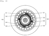
- FIG. 10 is a cross-sectional view taken along line A-A when an input shaft is rotated in a forward direction according to second, third, and fourth exemplary embodiments of the present invention.
- the input shaft 160 is inserted into the fixing shaft 500 and is rotatably installed thereon.
- the input shaft 160 is installed at the left side of the automatic transmission, i.e., at the first bearing 610 so as to be smoothly rotated on the fixing shaft 500, and the first sealing portion 710 is installed at the left side of the first bearing 610, i.e., between the fixing shaft 500 and the input shaft 160 and keeps an air-tight state of the fixing shaft 500 and the input shaft 160.
- a driving force transferring unit such as a belt or chain, may be hung on one side of the input shaft 160, and the sun gear 310 is formed on a right outer circumferential surface of the input shaft 160.
- a part of the input shaft 160 is inserted into the hub housing 400.
- the second sealing portion 720 is installed between the left outer circumferential surface of the input shaft 160 and the left inner circumferential surface of the hub housing 400 and keeps an air-tight state of the input shaft 160 and the hub housing 400.
- the second bearing 620 is installed at the right side of the second sealing portion 720, i.e., between the hub housing 400 and the input shaft 160.
- a first male buffering block 121 is fixed to the outer circumferential surface of the input shaft 160, and the first clutch block 110 is fixed to the inner circumferential surface of the hub housing 400.
- a first female buffering block 122 accommodates the first male buffering block 121, and the first clutch bearing 115 is installed between the first female buffering block 122 and the first clutch block 110.
- the first clutch includes the first male buffering block 121 and the first female buffering block 122, a spring, the first clutch block 110, and the first buffering clutch including the first clutch bearing 115.
- the first male buffering block 121 has first protrusion portions 130 and is fixed to the input shaft 160.
- the first female buffering block 122 is connected to the first male buffering block 121 in a state in which first hanging jaws 140 on which each of the first protrusion portions 130 is hung, are formed on the first female buffering block 122.
- the spring is installed between one of the first protrusion portions 130 and one of the first hanging jaws 140.
- the first clutch block 110 is fixed to the hub housing 400 and is fitted onto the first female buffering block 122.
- the first clutch bearing 115 is installed between the first female buffering block 122 and the first clutch block 110.
- the first male buffering block 121 is fixed to the input shaft 160, and the first protrusion portions 130 are formed on an outer circumferential surface of the first male buffering block 121.
- Each of the first protrusion portions 130 has a first protrusion 131, a fourth protrusion 134 formed at an opposite side to that of the first protrusion 131, a second protrusion 132 formed at the left side of the first protrusion 131, and a third protrusion 133 formed at an opposite side to that of the second protrusion 132.
- a first spring 111 is installed between the second protrusion 132 and the sixth protrusion 142, and a second spring 112 is installed between the second protrusion 132 and the seventh protrusion 143, and a third spring 113 is installed between the third protrusion 133 and the fifth protrusion 141, and a fourth spring 114 is installed between the third protrusion 133 and the eighth protrusion 144 so that rotation of the first male buffering block 121 is delayed for a predetermined time.
- the input shaft 160 is gradually rotated in the forward direction while the second protrusion 132 of the first protrusion portion 130 overcomes an elasticity of the first spring 111 and the third protrusion 133 of the first protrusion portion 130 overcomes an elasticity of the fourth spring 114.
- the first protrusion 131 is hung on the fifth protrusion 141 of a first hanging portion, and the fourth protrusion 134 is hung on the seventh protrusion 143 so that a forward driving force of the input shaft 160 is transferred to the first female buffering block 122.
- the first clutch bearing 115 is installed between the outer circumferential surface of the first female buffering block 122 and the first clutch block 110.
- a length of a long of the first clutch bearing 115 is formed to be greater than a gap between the first female buffering block 122 and the first clutch block 110, and a length of a the short radius of the first clutch bearing 115 is formed to be greater than the gap between the first female buffering block 122 and the first clutch block 110.
- the input shaft 160 is gradually rotated in the reverse direction while the second protrusion 132 of the first protrusion portion 130 overcomes the elasticity of the second spring 112 and the third protrusion 133 of the first protrusion portion 130 overcomes the elasticity of the third spring 113.
- the first protrusion 131 is hung on the sixth protrusion 142 of the first hanging jaw 140, and the fourth protrusion 134 is hung on the eighth protrusion 144 so that a reverse driving force of the input shaft 160 is transferred to the first female buffering block 122.
- the short radius of the first clutch bearing 115 is in contact with the first female buffering block 122 and the first clutch block 110, respectively, and or is spaced apart therefrom, and thus, locking of the first clutch bearing 115 is released.
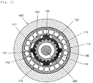
- FIG. 11 is a cross-sectional view taken along line A-A according to second, third, and fourth exemplary embodiments of the present invention and is a cross-sectional view when a driving force is not transferred to the input shaft.
- the first hanging jaw 140 and the first hanging portion are spaced apart from each other.
- first spring 111 and the second spring 112 provide the same elastic force at both sides of the second protrusion 132 and the third spring 113 and the fourth spring 114 provide the same elastic force to both sides of the third protrusion 133.
- FIG. 12 is a cross-sectional view taken along line C-C according to second and fifth exemplary embodiments of the present invention and is a cross-sectional view of a second buffering clutch that is a kind of the first sub-clutch .
- the second clutch includes a second buffering clutch including a second male buffering block 226, a second female buffering block 227, and a spring.
- the second male buffering block 226 has second protrusion portions 221 and is connected to the clutch block 214 as illustrated in Figs. 2 and 12 .
- the second female buffering block 227 is fixed to the carrier 340 and is connected to the second male buffering block 226 in a state in which second hanging jaws 220 on which each of the second protrusion portions 221 is hung, are formed.
- the spring is installed between one of the second protrusion portions 221 and one of the second hanging jaws 220.
- the spring includes a fifth spring 222 and a sixth spring 223 and a seventh spring 224 and an eighth spring 225.
- the springs are disposed based on the same principle as that of the first through fourth springs mentioned above, as illustrated in FIG. 12 .
- the second buffering clutch operates based on the same principle mentioned above, in which the first buffering clutch is rotated in the forward direction while the second male buffering block 226 is rotated in the forward direction.
- the second buffering clutch operates based on the same principle mentioned above, in which the first buffering clutch is rotated in the reverse direction while the second male buffering block 226 is rotated in the reverse direction.
- a maximum gap distance between the first hanging jaw 140 and the first protrusion portion 130 is greater than a maximum separation distance between the second hanging jaw 220 and the second protrusion portion 221.
- the locking gap of the first clutch is formed to be greater than the locking gap of the second clutch .
- FIG. 3 is a cross-sectional view of an automatic transmission according to a third exemplary embodiment of the present invention.
- An input shaft 160 is inserted into a fixing shaft 500 and is rotatably installed thereon.
- the input shaft 160 is installed at the left side of the automatic transmission, i.e., at a first bearing 610 so as to be smoothly rotated on the fixing shaft 500, and a first sealing portion 710 is installed at the left side of the first bearing 610, i.e., between the fixing shaft 500 and the input shaft 160 and keeps an air-tight state of the fixing shaft 500 and the input shaft 160.
- a driving force transferring unit such as a belt or chain, may be hung on one side of the input shaft 160, and a sun gear 310 is formed on a right outer circumferential surface of the input shaft 160.
- a part of the input shaft 160 is inserted into the hub housing 400.
- a second sealing portion 720 is installed between a left outer circumferential surface of the input shaft 160 and a left inner circumferential surface of the hub housing 400 and keeps an air-tight state of the input shaft 160 and the hub housing 400.
- the second bearing 620 is installed at a right side of the second sealing portion 720, i.e., between the hub housing 400 and the input shaft 160.
- a first male buffering block 121 is fixed to the outer circumferential surface of the input shaft 160, and the first clutch block 110 is fixed to the inner circumferential surface of the hub housing 400.
- a first female buffering block 122 accommodates the first male buffering block 121, and the first clutch bearing 115 is installed between the first female buffering block 122 and the first clutch block 110.
- FIG. 13 is a cross-sectional view taken along line C-C according to third and sixth exemplary embodiments of the present invention and is a cross-sectional view of a one way clutch that is a kind of the first sub-clutch.
- the second clutch includes a second clutch block 214, a third clutch block 230, and a second clutch bearing 231.
- the fixing shaft 500 is inserted into the second clutch block 214, wherein the gap exists between fixing shaft 500 and the second clutch block 214.
- the third clutch block 230 is fitted onto the second clutch block 214 and is fixed to the carrier 340.
- the second clutch bearing 231 is installed between the second clutch block 214 and the third clutch block 230.
- a length of a long of the second clutch bearing 231 is formed to be greater than a gap between the second clutch block 214 and the third clutch block 230, and a length of a the short radius of the second clutch bearing 231 is formed to be greater than the gap between the second clutch block 214 and the third clutch block 230.
- the third clutch block 230 to which the carrier 340 is fixed is rotated in the reverse direction.
- the third clutch block 230 is rotated in the reverse direction, the long of the second clutch bearing 231 is in contact with the third clutch block 230 and the second clutch block 214, respectively, and is locked.
- the cover housing 410 is installed on a right end of the hub housing 400.
- the cover housing 410 is inserted onto the fixing shaft 500 in a state in which the fifth clutch block 252 is installed in the cover housing 410.
- the cover housing 410 Since the third bearing 630 is installed between the fifth clutch block 252 and the fixing shaft 500, the cover housing 410 causes the hub housing 400 to be rotated.
- a third sealing portion 730 is installed on a right end of the third bearing 630 of the cover housing 410 and keeps an air-tight state between the cover housing 410 and the hub housing 400.
- the first sealing portion 710, the second sealing portion 720, and the third sealing portion 730 keep the air-tight state between the cover housing 410 and the hub housing 400.
- the first clutch is the above-mentioned first needle clutch, and the first sub-clutch may be configured by the above-mentioned second needle clutch.
- the first clutch is the above-mentioned first buffering clutch
- the first sub-clutch may be configured by the second buffering clutch.
- the first clutch is the above-mentioned first buffering clutch
- the first sub-clutch may be configured by the above-mentioned one way clutch.
- the first clutch is the above-mentioned first buffering clutch
- the first sub-clutch may be configured by the above-mentioned second needle clutch.
- the first clutch is the above-mentioned first needle clutch, and the first sub-clutch may be configured by the above-mentioned second buffering clutch.
- the first clutch is the above-mentioned needle clutch, and the first sub-clutch may be configured by the above-mentioned one way clutch.
- the automatic transmission of the present invention may be applied to various vehicles, such as motor cycles, vehicles, bicycles, two-wheeled motor cycles, three-wheeled motor cycles, and four-wheeled motor vehicles.
- first clutch block 111 first spring 112: second spring 113: third spring 114: fourth spring 115: first clutch bearing 1 21: first male buffering block 122: first female buffering block 130: first protrusion portion 131: first protrusion 132: second protrusion 133: third protrusion 134: fourth protrusion 140: first hanging jaw 141: fifth protrusion 142: sixth protrusion 143: seventh protrusion 144: eighth protrusion 160: input shaft 170: first retainer 171: first needle pin 172: first needle block 173: first groove 174: second groove 175: third groove 211: second needle block 212: second needle pin 213: second retainer 214: second clutch block 215: fourth groove 216: fifth groove 2
Landscapes
- Engineering & Computer Science (AREA)
- General Engineering & Computer Science (AREA)
- Mechanical Engineering (AREA)
- Structure Of Transmissions (AREA)
- Mechanical Operated Clutches (AREA)
Description
- This invention relates to an automatic transmission, and more particularly, to an automatic transmission that is capable of changing speed and moving forward or backward without using an additional device.
- A planetary gearbox is a combination of gears in a state in which sun gears, ring gears and planetary gears are disposed in a concentric line.
- In the case of an identical gear ratio, the planetary gearbox has a small volume, a concentric input/output and high power transmission efficiency compared to a gear train disposed in a gearbox that operates based on a different principle and thus is widely used in the field in which small size and lightweight are required.
- In the related art, Korean Patent Application No.
10-2005-0132839 - However, in Korean Patent Application No.
10-2005-0132839 - In order to solve the conventional problem, Korean Patent No.
1,190,755 - In the transmission disclosed in Korean Patent No.
1,190,755 - In the transmission disclosed in Korean Patent No.
1,190,755 - However, in Korean Patent No.
1,190,755 - Korean Patent No.
1,190,755 - Korean Patent Application No.
10-2005-0132839 - A problem to be solved by the present invention is providing an automatic transmission in which a hub housing may be rotated both, in a forward as well as in a reverse direction when it is driven from the output side, wherein the transmission ratio is 1:1 when the input shaft is driven from the input side in the forward direction, and the transmission ratio is different from 1:1 when the input shaft is driven from the input side in the reverse direction.
- This problem is solved by an automatic transmission according to claim 1. The dependent claims concern particular embodiments of the invention as claimed in claim 1.
- As described above, the present invention has the following effects.
- First, a hub housing can be rotated in a reverse direction so that an automatic transmission according to the present invention can move backward.
- Second, the automatic transmission can perform transmission and move forward or backward without using an additional device.
- Third, even though the hub housing is rotated in the reverse direction and is capable of moving backward, the hub housing can be output in the forward direction at a constant gear ratio when an input shaft is rotated in a forward direction, and the hub housing can be output in the forward direction at a large gear ratio when the input shaft is rotated in the reverse direction.
- Fourth, a second clutch may include several sub-clutches so that a clutch suitable for environment can be selected.
- Fifth, a first clutch may include a first needle clutch or a first buffering clutch so that component replacement and manufacturing can be very easily performed.
- Sixth, a second sub-clutch may include one of a needle clutch, a buffering clutch and a one way clutch so that component replacement and manufacturing can be very easily performed.
- Seventh, since a locking gap of the first clutch is formed to be greater than a locking gap of the second clutch, the second clutch gets loose prior to the first clutch when the hub housing is rotated in the reverse direction so that locking is released and the automatic transmission can easily move backward.
- Eighth, a concentric block with a gap is installed so that a moving-backward operation of the hub housing can be smoothly performed when the hub housing is rotated in the reverse direction.
- Ninth, the locking gap of the first clutch and a locking gap of the second buffering clutch, a second needle clutch or a one way clutch are formed to be greater than the locking gap of the second sub-clutch so that the second sub-clutch linked to a third sub-clutch is unlocked prior to the first clutch when the hub housing is reversely rotated and thus the moving-backward operation of the hub housing can be smoothly performed when the hub housing is rotated in the reverse direction.
-
-
FIG. 1 is a cross-sectional view of an automatic transmission according to a first exemplary embodiment of the present invention. -
FIG. 2 is a cross-sectional view of an automatic transmission according to a second exemplary embodiment of the present invention. -
FIG. 3 is a cross-sectional view of an automatic transmission according to a third exemplary embodiment of the present invention. -
FIG. 4 is a cross-sectional view of a first needle clutch taken along line A-A according to first, fifth, and sixth exemplary embodiments of the present invention. -
FIG. 5 is a cross-sectional view taken along line B-B of a planetary gear portion according to exemplary embodiments of the present invention. -
FIG. 6 is a cross-sectional view taken along line C-C according to first and fourth exemplary embodiments of the present invention and is a cross-sectional view of a second needle clutch that is a kind of a first sub-clutch. -
FIG. 7 is a cross-sectional view taken along line D-D according to exemplary embodiments of the present invention and is a cross-sectional view of a second sub-clutch. -
FIG. 8 is a cross-sectional view taken along line E-E according to exemplary embodiments of the present invention and is a cross-sectional view of a third sub-clutch. -
FIG. 9 is a cross-sectional view taken along line A-A when an input shaft is rotated in a reverse direction according to second, third, and fourth exemplary embodiments of the present invention. -
FIG. 10 is a cross-sectional view taken along line A-A when an input shaft is rotated in a forward direction according to second, third, and fourth exemplary embodiments of the present invention. -
FIG. 11 is a cross-sectional view taken along line A-A according to second, third, and fourth exemplary embodiments of the present invention when a driving force is not transferred to the input shaft. -
FIG. 12 is a cross-sectional view taken along line C-C according to second and fifth exemplary embodiments of the present invention and is a cross-sectional view of a second buffering clutch that is a kind of a first sub-clutch. -
FIG. 13 is a cross-sectional view taken along line C-C according to third and sixth exemplary embodiments of the present invention and is a cross-sectional view of a one way clutch that is a kind of a first sub-clutch. - The present invention will now be described in detail with reference to the attached drawings.
-
FIG. 1 is a cross-sectional view of an automatic transmission according to a first exemplary embodiment of the present invention,FIG. 2 is a cross-sectional view of an automatic transmission according to a second exemplary embodiment of the present invention, andFIG. 3 is a cross-sectional view of an automatic transmission according to a third exemplary embodiment of the present invention. - First, the entire configuration of the present invention will be briefly mentioned and thus a detailed configuration and operation principle thereof will be described later.
- Also, in the following descriptions, a clockwise direction is defined as a forward direction and a counterclockwise direction is defined as a reverse direction based on the drawings and it will be described.
- Also, it will be noted that the present invention includes a first clutch and a second clutch. The first clutch includes a first needle clutch illustrated in
FIG. 6 and a first buffering clutch illustrated inFIG. 7 . - It will be noted that the second clutch includes a first sub-clutch , a second sub-clutch , and a third sub-clutch .
- Also, it will be noted in advance that a locking gap of the second sub-clutch may be preferably formed to be smaller than a locking gap of the first clutch and a locking gap of the first sub-clutch .
- The first sub-clutch may be connected to an opposite side to a
satellite gear 320 installed at a planetary gear portion and may confine acarrier 340 to be rotated in the reverse direction. - The second sub-clutch may be connected to the first sub-clutch .
- One side of the third sub-clutch may be connected to a hub housing 400, and the other side of the third sub-clutch may be connected to the second sub-clutch so that the third sub-clutch may confine reverse rotation of the hub housing 400.
- It will also be noted that the first sub-clutch includes one of a second needle clutch that is illustrated in
FIG. 9 , a second buffering clutch illustrated inFIG. 10 , and a one way clutch illustrated inFIG. 11 , which will be described later. - First, an automatic transmission according to a first exemplary embodiment of the present invention will be described in detail with reference to the attached drawings.
- An
input shaft 160 is inserted into afixing shaft 500 and is rotatably installed thereon. - The
input shaft 160 is installed at the left side of the automatic transmission, i.e., at afirst bearing 610 so as to be smoothly rotated on thefixing shaft 500, and afirst sealing portion 710 is installed at the left side of the first bearing 610, i.e., between thefixing shaft 500 and theinput shaft 160 and keeps an air-tight state of thefixing shaft 500 and theinput shaft 160. - A driving force transferring unit, such as a belt or chain, may be hung on one side of the
input shaft 160, and asun gear 310 is formed on a right outer circumferential surface of theinput shaft 160. - A part of the
input shaft 160 is inserted into the hub housing 400. - A
second sealing portion 720 is installed between a left outer circumferential surface of theinput shaft 160 and a left inner circumferential surface of the hub housing 400 and keeps an air-tight state of theinput shaft 160 and the hub housing 400. - The second bearing 620 is installed at a right side of the
second sealing portion 720, i.e., between the hub housing 400 and theinput shaft 160. - A
first needle block 172 is fixed to theinput shaft 160. - A first
clutch block 110 is fitted onto thefirst needle block 172 and is connected to thehub housing 400. - A
first retainer 170 is installed between thefirst needle block 172 and the firstclutch block 110. - A plurality of first needle pins 171 are installed in the
first retainer 170. - The first needle clutch includes the
first needle block 172 and the firstclutch block 110, thefirst retainer 170, and thefirst needle pin 171. -
FIG. 4 is a cross-sectional view of a first needle clutch taken along line A-A according to first, fifth, and sixth exemplary embodiments of the present invention. - Since the
first needle block 172 is fitted onto an outer surface of theinput shaft 160 and is fixed to theinput shaft 160, thefirst needle block 172 is rotated together with theinput shaft 160. - The first
clutch block 110 is connected to an inner circumferential surface of thehub housing 400 and is rotated together with thehub housing 400. - The
first retainer 170 includes a plurality of first needle pins 171 and is installed between thefirst needle block 172 and the firstclutch block 110. - A
first groove 173 is formed in an outer circumferential surface of thefirst needle block 172 so that thefirst groove 173 is formed to be close to thefirst retainer 170. - A
second groove 174 slantly extends from thefirst groove 173, and athird groove 175 extends from thesecond groove 174, and thefirst needle pin 171 is accommodated in thethird groove 175. - In other words, since the
third groove 175 is formed to be concave in a direction of a center of rotation of the firstclutch block 110, when thefirst needle pin 171 is placed in thethird groove 175, thefirst needle pin 171 may freely move between the firstclutch block 110 and thefirst needle block 172. - The
first groove 173, thesecond groove 174, and thethird groove 175 are consecutively formed along the outer circumferential surface of thefirst needle block 172, and thefirst needle pin 171 is preferably included in eachthird groove 175. - In other words, a shortest distance from the
third groove 175 to the firstclutch block 110 is formed to be greater than or equal to a diameter of thefirst needle pin 171, and a minimum value of a shortest distance from thesecond groove 174 to the firstclutch block 110 is formed to be smaller than the diameter of thefirst needle pin 171. - When the
input shaft 160 is rotated in the reverse direction, thefirst needle block 172 is rotated in the reverse direction, and all of thefirst groove 173, thesecond groove 174, and thethird groove 175 are rotated in the reverse direction. Thus, thefirst needle pin 171 is placed in thethird groove 175 and moves freely so that thefirst needle block 172 and the firstclutch block 110 are not confined with respect to each other and thus locking of the first needle clutch is released. - Contrary to this, when the
input shaft 160 is rotated in the forward direction, thefirst needle block 172 is rotated in the forward direction, and all of thefirst groove 173, thesecond groove 174, and thethird groove 175 are rotated in the forward direction. Thus, thefirst needle pin 171 leaves thethird groove 175 and is gradually in close contact with the firstclutch block 110 by thesecond groove 174 formed to be long. - When the
input shaft 160 is continuously rotated in the forward direction, thefirst needle pin 171 is leaning to a right side of thesecond groove 174 ofFigure 4 detail view and meets a limitation at which thefirst needle pin 171 cannot move in a direction of thefirst groove 173 any more. As a result, thefirst needle pin 171 is in a locked state in which it is fixed between the firstclutch block 110 and thesecond groove 174. - In other words, when the
input shaft 160 is rotated in the forward direction, the firstclutch block 110 and thefirst needle block 172 are locked with respect to each other. Thus, the firstclutch block 110 is rotated in the forward direction so that thehub housing 400 is output in the forward direction. -
FIG. 5 is a cross-sectional view taken along line B-B of a planetary gear portion according to exemplary embodiments of the present invention. - The
satellite gear 320 is rotatably installed at acarrier pin 330 of the planetary gear portion that is fixed to acarrier 340. Thesatellite gear 320 is engaged between thesun gear 310 rotated on the fixingshaft 500 and thering gear 350 fixed to thehub housing 400. -
FIG. 6 is a cross-sectional view taken along line C-C according to first and fourth exemplary embodiments of the present invention and is a cross-sectional view of a second needle clutch that is a kind of a first sub-clutch. - A
second needle block 211 is fitted onto the secondclutch block 214 and is formed in a side of thecarrier 340. - A
second retainer 213 is installed between the secondclutch block 214 and thesecond needle block 211, and a plurality of second needle pins 212 are installed at thesecond retainer 213. - In more detail, a
fourth groove 215 is formed in an inner circumferential surface of thesecond needle block 211. - The
fourth groove 215 is formed to be concave in a direction of thehub housing 400 on inner walls of thesecond needle block 211 as thefourth groove 215 gets closer to thesecond retainer 213 in the reverse direction. - A
fifth groove 216 is formed to be inclined to be gradually close to a direction of a center of the fixingshaft 500 as thefifth groove 216 extends from thefourth groove 215 and gets closer to the forward direction. - In other words, a shortest distance from the
fourth groove 215 to the secondclutch block 214 is formed to be greater than or equal to the diameter of thesecond needle pin 212, and a minimum value of a shortest distance from thefifth groove 216 to the secondclutch block 214 is formed to be smaller than the diameter of thesecond needle pin 212. - Thus, when the first
clutch block 110 connected to thehub housing 400 is rotated in the forward direction, thesecond needle pin 212 leaves thefourth groove 215 and is directed toward thefifth groove 216 based on the same principle as that of the first needle clutch described above. - A length of the
second groove 174 may be formed to be greater than that of thefifth groove 216. This is the same principle as that of a configuration in which the locking gap of the first clutch is formed to be greater than the locking gap of the second clutch . A detailed operation principle thereof will be described later. -
FIG. 7 is a cross-sectional view taken along line D-D according to exemplary embodiments of the present invention and is a cross-sectional view of a second sub-clutch. - Since a
concentric block 245 is installed on the fixingshaft 500 to have a gap therebetween, theconcentric block 245 is installed on the fixingshaft 500 to very slightly move in vertical and horizontal directions based on the drawings. - A stop washer is installed on the fixing
shaft 500, and a spring is installed between theconcentric block 245 and the stop washer. - In more detail, a
first stop washer 810 and asecond stop washer 820 are installed on a right side of the fixingshaft 500 inside thehub housing 400, so as to be spaced apart from each other and are fixed to the fixingshaft 500. - The
concentric block 245 is installed between thefirst stop washer 810 and thesecond stop washer 820, and aconcentric spring 232 is installed between theconcentric block 245 and thefirst stop washer 810 and between theconcentric block 245 and thesecond stop washer 820. - The
concentric spring 232 serves to maintain a concentric state so that theconcentric block 245 may move slightly. - The second
clutch block 214 is fitted onto theconcentric block 245. - The
third retainer 242 is installed between the secondclutch block 214 and theconcentric block 245. - A plurality of
clutch shoes 243 are installed at thethird retainer 242. - A third
clutch bearing 241 is installed at the plurality ofclutch shoes 243 so that theclutch shoes 243 may be rotated. - The
third retainer 242 is fixed to the fourthclutch block 251 that will be described later. - A
spline portion 244 is fixedly installed onto the fixingshaft 500, and theconcentric block 245 is fixed to thespline portion 244. - The
third retainer 242 is installed at theclutch shoes 243 between the thirdclutch bearing 241 and theconcentric block 245. - A lengthwise length of each of the
clutch shoes 243 may be formed to be equal to or greater than a gap between theconcentric block 245 and the secondclutch block 214. - Thus, when the
third retainer 242 is rotated in the reverse direction, theclutch shoes 243 are inclined in the forward direction based on the thirdclutch bearing 241, and theclutch shoes 243 slid between theconcentric block 245 and the secondclutch block 214 and thus, locking of theclutch shoes 243 is released. - Contrary to this, when the
third retainer 242 is rotated in the forward direction, theclutch shoes 243 are inclined in the reverse direction based on the thirdclutch bearing 241, and when theclutch shoes 243 are caught between theconcentric block 245 and the secondclutch block 214, the secondclutch block 214 and theconcentric block 245 are locked with respect to each other. -
FIG. 8 is a cross-sectional view taken along line E-E according to exemplary embodiments of the present invention and is a cross-sectional view of a third sub-clutch. - The fourth
clutch block 251 is fitted onto the fixingshaft 500. - The fifth
clutch block 252 is fitted onto the fourthclutch block 251 and is fixed to acover housing 410 installed at thehub housing 400. - The fourth
clutch bearing 253 is installed between the fourthclutch block 251 and the fifthclutch block 252. - Since the fifth
clutch block 252 is fixed to thecover housing 410, the fifthclutch block 252 is rotated together with thehub housing 400 to which thecover housing 410 is fixed. - A length of a long radius of the fourth
clutch bearing 253 is formed to be greater than a gap between the fourthclutch block 251 and the fifthclutch block 252, and a length of the fourthclutch bearing 253 having a small radius is formed to be greater than the gap between the fourthclutch block 251 and the fifthclutch block 252. - Thus, the fifth
clutch block 252 is rotated in the forward direction as thehub housing 400 is rotated in the forward direction. Thus, the short radius of the fourthclutch bearing 253 is in contact with the fourthclutch block 251 and the fifthclutch block 252, respectively, and slides and thus locking of the fourthclutch bearing 253 is released. - When locking of the third sub-clutch is released, the
hub housing 400 may be continuously rotated in the forward direction. - Contrary to this, the fifth
clutch block 252 is rotated in the reverse direction as thehub housing 400 is rotated in the reverse direction. Thus, the long radius of the fourthclutch bearing 253 is in contact with the fourthclutch block 251 and the fifthclutch block 252, respectively, and is caught therein and thus is locked. - When the third sub-clutch is locked, the fourth
clutch block 251 is also rotated in the reverse direction when thehub housing 400 is continuously rotated in the reverse direction. - An operation of an automatic transmission according to the first embodiment of the present invention will be described with reference to the above description.
- When the
input shaft 160 is used as a driving force input portion and is rotated in the forward direction, thefirst needle block 172 of the first needle clutch is rotated in the forward direction. - As the
first needle block 172 is rotated in the forward direction, thefirst needle pin 171 is locked in thesecond groove 174, and the firstclutch block 110 is rotated in the forward direction. - Since the first
clutch block 110 is fixed to thehub housing 400, thehub housing 400 is output in the forward direction by the firstclutch block 110 that is rotated in the forward direction. - As the
input shaft 160 is rotated in the forward direction, thesun gear 310 is also rotated in the forward direction, and thesatellite gear 320 engaged with thesun gear 310 is rotated in the reverse direction. - When the
satellite gear 320 is rotated in the forward direction and thus is rotated in the reverse direction along thering gear 350, thecarrier pin 330 revolves around the fixingshaft 500 in the forward direction, and thus, thecarrier 340 is rotated in the forward direction. - Since the
carrier 340 is connected to thesecond needle block 211, thesecond needle pin 212 is placed in thefourth groove 215 formed in thesecond needle block 211 as thecarrier 340 is rotated in the forward direction. Thus, the second needle clutch is released, as mentioned above. - As a result, locking of the second clutch is released when the
input shaft 160 is rotated in the forward direction. - Thus, the
hub housing 400 may be continuously driven in the forward direction as theinput shaft 160 is rotated in the forward direction. - When the
input shaft 160 is used as the driving force input portion and is rotated in the reverse direction, thefirst needle block 172 of the first needle clutch is rotated in the reverse direction. - As the
first needle block 172 is rotated in the reverse direction, thefirst needle pin 171 is placed in thethird groove 175 and locking of thefirst needle pin 171 is released so that power is not transferred to the firstclutch block 110. - As the
input shaft 160 is rotated in the reverse direction, thesun gear 310 is also rotated in the reverse direction, and thesatellite gear 320 engaged with thesun gear 310 is rotated in the forward direction. - When the
satellite gear 320 is rotated in the forward direction and is rotated in the reverse direction along thering gear 350, thecarrier pin 330 starts reverse revolution around the fixingshaft 500, and as such, thecarrier 340 is rotated in the reverse direction. - Since the
carrier 340 is connected to thesecond needle block 211, as thecarrier 340 is rotated in the reverse direction, thesecond needle pin 212 is caught in thefifth groove 216 formed in thesecond needle block 211. Thus, the second needle clutch is locked, as mentioned above. - As a result, when the
input shaft 160 is rotated in the reverse direction, the second clutch is locked in the reverse direction. - As the
carrier 340 is locked in the reverse direction, thecarrier 340 is fixed to fixingshaft 500 byconcentric block 245 with secondclutch block 214, and thesatellite gear 320 is rotated in the forward direction. Thus, thering gear 350 is decelerated and is rotated in the forward direction. - Thus, as the
input shaft 160 is rotated in the reverse direction, thehub housing 400 is decelerated and may be driven in the forward direction. - Next, in first through sixth exemplary embodiments of the present invention, an operation of the
hub housing 400 when thehub housing 400 is used as an input portion and is driven in the forward direction, will be described below. - When the
hub housing 400 is used as the driving force input portion and is rotated in the forward direction, thecover housing 410 fixed to thehub housing 400 is rotated in the forward direction. - Since the fifth
clutch block 252 is fixed to thecover housing 410, the fifthclutch block 252 is also rotated in the forward direction when thecover housing 410 is rotated in the forward direction. - A length of a long radius of the fourth
clutch bearing 253 is formed to be greater than the gap between the fourthclutch block 251 and the fifthclutch block 252, and a length of a the short radius of the fourthclutch bearing 253 is formed to be greater than the gap between the fourthclutch block 251 and the fifthclutch block 252. - Thus, when the fifth
clutch block 252 is rotated in the forward direction as thehub housing 400 is rotated in the forward direction, the the short radius of the fourthclutch bearing 253 is in contact with the fourthclutch block 251 and the fifthclutch block 252, respectively, and slides and thus, locking of the fourthclutch bearing 253 is released. - In other words, when locking of the third sub-clutch that is a kind of the second clutch is released, the
hub housing 400 may be continuously rotated in the forward direction. - As the
hub housing 400 is rotated in the forward direction, a distance between a driving shaft and the firstclutch block 110 of the first needle clutch installed on inner walls of thehub housing 400 is formed to be uniform, and no groove is formed in the firstclutch block 110. Thus, power is not transferred to thefirst needle block 172 so that thehub housing 400 may be continuously rotated in the forward direction. - Next, in first through sixth exemplary embodiments of the present invention, a moving-backward operation of the
hub housing 400 when thehub housing 400 is used as an input portion and is driven in the reverse direction, will be described below. - When the
hub housing 400 is used as a driving force input portion and is rotated in the reverse direction, thecover housing 410 fixed to thehub housing 400 is rotated in the reverse direction. - Since fifth
clutch block 252 is fixed to thecover housing 410, the fifthclutch block 252 is also rotated in the reverse direction when thecover housing 410 is rotated in the reverse direction. - A length of a long of the fourth
clutch bearing 253 is formed to be greater than the gap between the fourthclutch block 251 and the fifthclutch block 252, and a length of a the short radius of the fourthclutch bearing 253 is formed to be greater than the gap between the fourthclutch block 251 and the fifthclutch block 252. - Thus, when the
hub housing 400 is rotated in the reverse direction and the fifthclutch block 252 is rotated in the reverse direction, the long of the fourthclutch bearing 253 is in contact with the fourthclutch block 251 and the fifthclutch block 252, respectively, and is locked. - Since the fourth
clutch block 251 is connected to thethird retainer 242, when the fourthclutch block 251 is rotated in the reverse direction, and thethird retainer 242 is rotated in the reverse direction. - When the
third retainer 242 is rotated in the reverse direction, theclutch shoes 243 are inclined in the forward direction based on the thirdclutch bearing 241. As a result, theclutch shoes 243 slid between theconcentric block 245 and the secondclutch block 214 and thus, locking of theclutch shoes 243 is released. - In other words, since the second sub-clutch that is a kind of the second clutch is released, the moving-backward operation of the
hub housing 400 may be performed. - In more detail, the locking gap of the first clutch and the locking gap of the first sub-clutch are formed to be greater than that of the second sub-clutch .
- Thus, when the
hub housing 400 is rotated in the reverse direction, locking of the second sub-clutch linked to the third sub-clutch is released prior to the first clutch so that the moving-backward operation of thehub housing 400 may be performed. - In this case, it is noted that the first sub-clutch may include the second needle clutch, the second buffering clutch, or the one way clutch, as mentioned above.
- Also, in the first exemplary embodiment of the present invention, a distance between the driving shaft and the first
clutch block 110 of the first needle clutch installed on the inner walls of thehub housing 400 is formed to be uniform, and no groove is formed in the firstclutch block 110 and thus, power is not transferred to thefirst needle block 172. - In this case, since the
clutch shoes 243 of the second sub-clutch are released prior to the first clutch , thehub housing 400 may be rotated in the reverse direction regardless of the first clutch so that the moving-backward operation of thehub housing 400 may be performed. - The locking gap of the first clutch that is greater than the locking gap of the second clutch will be described in more detail below.
- When the
hub housing 400 is rotated in the reverse direction, thering gear 350 is also rotated in the reverse direction, and thesatellite gear 320 engaged with thering gear 350 is also rotated in the reverse direction. - When the
satellite gear 320 is rotated in the reverse direction, thecarrier 340 is rotated in the reverse direction. - When the
carrier 340 is rotated in the reverse direction, the second needle clutch is locked, as mentioned above. Thus, at some time, thecarrier 340 is not rotated in the reverse direction any more and is locked. - When the
carrier 340 is locked, thesun gear 310 engaged with thesatellite gear 320 that is rotated in the reverse direction is rotated in the forward direction. - When the
sun gear 310 is rotated in the forward direction, as mentioned above, the first needle clutch that is a kind of the first clutch is locked, and thehub housing 400 is driven in the forward direction. - As a result, the
hub housing 400 is used as an input portion and transfers a reverse driving force and thecarrier 340 is locked, theinput shaft 160 to be output is output in the forward direction, and thehub housing 400 is rotated in the forward direction. Thus, contradiction in which driving forces in opposite directions collide with each other, occurs so that the moving-backward operation of thehub housing 400 may not be performed. - Thus, when the second clutch is released before the first clutch is locked, contradiction of driving force collision is solved, and the moving-backward operation of the
hub housing 400 may be performed. - Next, the second exemplary embodiment of the present invention will be described with reference to the attached drawings.
-
FIG. 2 is a cross-sectional view of an automatic transmission according to a second exemplary embodiment of the present invention. -
FIG. 9 is a cross-sectional view taken along line A-A when an input shaft is rotated in a reverse direction according to second, third, and fourth exemplary embodiments of the present invention, andFIG. 10 is a cross-sectional view taken along line A-A when an input shaft is rotated in a forward direction according to second, third, and fourth exemplary embodiments of the present invention. - The
input shaft 160 is inserted into the fixingshaft 500 and is rotatably installed thereon. - The
input shaft 160 is installed at the left side of the automatic transmission, i.e., at thefirst bearing 610 so as to be smoothly rotated on the fixingshaft 500, and thefirst sealing portion 710 is installed at the left side of thefirst bearing 610, i.e., between the fixingshaft 500 and theinput shaft 160 and keeps an air-tight state of the fixingshaft 500 and theinput shaft 160. - A driving force transferring unit, such as a belt or chain, may be hung on one side of the
input shaft 160, and thesun gear 310 is formed on a right outer circumferential surface of theinput shaft 160. - A part of the
input shaft 160 is inserted into thehub housing 400. - The
second sealing portion 720 is installed between the left outer circumferential surface of theinput shaft 160 and the left inner circumferential surface of thehub housing 400 and keeps an air-tight state of theinput shaft 160 and thehub housing 400. - The
second bearing 620 is installed at the right side of thesecond sealing portion 720, i.e., between thehub housing 400 and theinput shaft 160. - A first
male buffering block 121 is fixed to the outer circumferential surface of theinput shaft 160, and the firstclutch block 110 is fixed to the inner circumferential surface of thehub housing 400. - A first
female buffering block 122 accommodates the firstmale buffering block 121, and the firstclutch bearing 115 is installed between the firstfemale buffering block 122 and the firstclutch block 110. - The first clutch includes the first
male buffering block 121 and the firstfemale buffering block 122, a spring, the firstclutch block 110, and the first buffering clutch including the firstclutch bearing 115. - In other words, the first
male buffering block 121 hasfirst protrusion portions 130 and is fixed to theinput shaft 160. - The first
female buffering block 122 is connected to the firstmale buffering block 121 in a state in which first hangingjaws 140 on which each of thefirst protrusion portions 130 is hung, are formed on the firstfemale buffering block 122. - The spring is installed between one of the
first protrusion portions 130 and one of the first hangingjaws 140. - The first
clutch block 110 is fixed to thehub housing 400 and is fitted onto the firstfemale buffering block 122. - The first
clutch bearing 115 is installed between the firstfemale buffering block 122 and the firstclutch block 110. - In more detail, the first
male buffering block 121 is fixed to theinput shaft 160, and thefirst protrusion portions 130 are formed on an outer circumferential surface of the firstmale buffering block 121. - Each of the
first protrusion portions 130 has afirst protrusion 131, afourth protrusion 134 formed at an opposite side to that of thefirst protrusion 131, asecond protrusion 132 formed at the left side of thefirst protrusion 131, and athird protrusion 133 formed at an opposite side to that of thesecond protrusion 132. - A
fifth protrusion 141 on which thefirst protrusion 131 is hung when thefirst protrusion 131 is rotated in the forward direction, aseventh protrusion 143 on which thefourth protrusion 134 is hung when thefourth protrusion 134 is rotated in the reverse direction, asixth protrusion 142 that is close to thesecond protrusion 132 when thesecond protrusion 132 is rotated in the forward direction, and aneighth protrusion 144 that is close to thethird protrusion 133 when thethird protrusion 133 is rotated in the forward direction, are formed on an inner circumferential surface of the firstfemale buffering block 122. - A
first spring 111 is installed between thesecond protrusion 132 and thesixth protrusion 142, and asecond spring 112 is installed between thesecond protrusion 132 and theseventh protrusion 143, and athird spring 113 is installed between thethird protrusion 133 and thefifth protrusion 141, and afourth spring 114 is installed between thethird protrusion 133 and theeighth protrusion 144 so that rotation of the firstmale buffering block 121 is delayed for a predetermined time. - Next, an operation of the first clutch according to second, third, and fourth exemplary embodiments of the present invention will be described.
- The
input shaft 160 is gradually rotated in the forward direction while thesecond protrusion 132 of thefirst protrusion portion 130 overcomes an elasticity of thefirst spring 111 and thethird protrusion 133 of thefirst protrusion portion 130 overcomes an elasticity of thefourth spring 114. - After a predetermined time elapses, the
first protrusion 131 is hung on thefifth protrusion 141 of a first hanging portion, and thefourth protrusion 134 is hung on theseventh protrusion 143 so that a forward driving force of theinput shaft 160 is transferred to the firstfemale buffering block 122. - The first
clutch bearing 115 is installed between the outer circumferential surface of the firstfemale buffering block 122 and the firstclutch block 110. - A length of a long of the first
clutch bearing 115 is formed to be greater than a gap between the firstfemale buffering block 122 and the firstclutch block 110, and a length of a the short radius of the firstclutch bearing 115 is formed to be greater than the gap between the firstfemale buffering block 122 and the firstclutch block 110. - Thus, when the
input shaft 160 is rotated in the forward direction and the firstmale buffering block 121 is rotated in the forward direction, the long of the firstclutch bearing 115 is in contact with the firstfemale buffering block 122 and the firstclutch block 110, respectively, and is locked. - The
input shaft 160 is gradually rotated in the reverse direction while thesecond protrusion 132 of thefirst protrusion portion 130 overcomes the elasticity of thesecond spring 112 and thethird protrusion 133 of thefirst protrusion portion 130 overcomes the elasticity of thethird spring 113. - As a result, after a predetermined time elapses, the
first protrusion 131 is hung on thesixth protrusion 142 of the first hangingjaw 140, and thefourth protrusion 134 is hung on theeighth protrusion 144 so that a reverse driving force of theinput shaft 160 is transferred to the firstfemale buffering block 122. - When the
input shaft 160 is rotated in the reverse direction and the firstmale buffering block 121 is rotated in the reverse direction, the the short radius of the firstclutch bearing 115 is in contact with the firstfemale buffering block 122 and the firstclutch block 110, respectively, and or is spaced apart therefrom, and thus, locking of the firstclutch bearing 115 is released. -
FIG. 11 is a cross-sectional view taken along line A-A according to second, third, and fourth exemplary embodiments of the present invention and is a cross-sectional view when a driving force is not transferred to the input shaft. - Since the driving force is not transferred to the
input shaft 160, the first hangingjaw 140 and the first hanging portion are spaced apart from each other. - This is because the
first spring 111 and thesecond spring 112 provide the same elastic force at both sides of thesecond protrusion 132 and thethird spring 113 and thefourth spring 114 provide the same elastic force to both sides of thethird protrusion 133. -
FIG. 12 is a cross-sectional view taken along line C-C according to second and fifth exemplary embodiments of the present invention and is a cross-sectional view of a second buffering clutch that is a kind of the first sub-clutch . - The second clutch includes a second buffering clutch including a second
male buffering block 226, a secondfemale buffering block 227, and a spring. - The second
male buffering block 226 hassecond protrusion portions 221 and is connected to theclutch block 214 as illustrated inFigs. 2 and12 . - The second
female buffering block 227 is fixed to thecarrier 340 and is connected to the secondmale buffering block 226 in a state in which second hangingjaws 220 on which each of thesecond protrusion portions 221 is hung, are formed. - The spring is installed between one of the
second protrusion portions 221 and one of thesecond hanging jaws 220. - In more detail, the spring includes a
fifth spring 222 and asixth spring 223 and aseventh spring 224 and aneighth spring 225. The springs are disposed based on the same principle as that of the first through fourth springs mentioned above, as illustrated inFIG. 12 . - If the
hub housing 400 is used as an input portion and is rotated in the forward direction, the second buffering clutch operates based on the same principle mentioned above, in which the first buffering clutch is rotated in the forward direction while the secondmale buffering block 226 is rotated in the forward direction. - Similarly, if the
hub housing 400 is used as the input portion and is rotated in the reverse direction, the second buffering clutch operates based on the same principle mentioned above, in which the first buffering clutch is rotated in the reverse direction while the secondmale buffering block 226 is rotated in the reverse direction. - In this case, a maximum gap distance between the first hanging
jaw 140 and thefirst protrusion portion 130 is greater than a maximum separation distance between thesecond hanging jaw 220 and thesecond protrusion portion 221. - That is, the locking gap of the first clutch is formed to be greater than the locking gap of the second clutch .
- Next, a third exemplary embodiment of the present invention will be described with reference to the attached drawings.
-
FIG. 3 is a cross-sectional view of an automatic transmission according to a third exemplary embodiment of the present invention. - An
input shaft 160 is inserted into a fixingshaft 500 and is rotatably installed thereon. - The
input shaft 160 is installed at the left side of the automatic transmission, i.e., at afirst bearing 610 so as to be smoothly rotated on the fixingshaft 500, and afirst sealing portion 710 is installed at the left side of thefirst bearing 610, i.e., between the fixingshaft 500 and theinput shaft 160 and keeps an air-tight state of the fixingshaft 500 and theinput shaft 160. - A driving force transferring unit, such as a belt or chain, may be hung on one side of the
input shaft 160, and asun gear 310 is formed on a right outer circumferential surface of theinput shaft 160. - A part of the
input shaft 160 is inserted into thehub housing 400. - A
second sealing portion 720 is installed between a left outer circumferential surface of theinput shaft 160 and a left inner circumferential surface of thehub housing 400 and keeps an air-tight state of theinput shaft 160 and thehub housing 400. - The
second bearing 620 is installed at a right side of thesecond sealing portion 720, i.e., between thehub housing 400 and theinput shaft 160. - A first
male buffering block 121 is fixed to the outer circumferential surface of theinput shaft 160, and the firstclutch block 110 is fixed to the inner circumferential surface of thehub housing 400. - A first
female buffering block 122 accommodates the firstmale buffering block 121, and the firstclutch bearing 115 is installed between the firstfemale buffering block 122 and the firstclutch block 110. -
FIG. 13 is a cross-sectional view taken along line C-C according to third and sixth exemplary embodiments of the present invention and is a cross-sectional view of a one way clutch that is a kind of the first sub-clutch. - The second clutch includes a second
clutch block 214, a thirdclutch block 230, and a secondclutch bearing 231. - The fixing
shaft 500 is inserted into the secondclutch block 214, wherein the gap exists between fixingshaft 500 and the secondclutch block 214. - The third
clutch block 230 is fitted onto the secondclutch block 214 and is fixed to thecarrier 340. - The second
clutch bearing 231 is installed between the secondclutch block 214 and the thirdclutch block 230. - A length of a long of the second
clutch bearing 231 is formed to be greater than a gap between the secondclutch block 214 and the thirdclutch block 230, and a length of a the short radius of the secondclutch bearing 231 is formed to be greater than the gap between the secondclutch block 214 and the thirdclutch block 230. - Thus, when the
carrier 340 is rotated in the reverse direction, the thirdclutch block 230 to which thecarrier 340 is fixed, is rotated in the reverse direction. - If the third
clutch block 230 is rotated in the reverse direction, the long of the secondclutch bearing 231 is in contact with the thirdclutch block 230 and the secondclutch block 214, respectively, and is locked. - The
cover housing 410 is installed on a right end of thehub housing 400. - The
cover housing 410 is inserted onto the fixingshaft 500 in a state in which the fifthclutch block 252 is installed in thecover housing 410. - Since the
third bearing 630 is installed between the fifthclutch block 252 and the fixingshaft 500, thecover housing 410 causes thehub housing 400 to be rotated. - A
third sealing portion 730 is installed on a right end of thethird bearing 630 of thecover housing 410 and keeps an air-tight state between thecover housing 410 and thehub housing 400. - Since a fluid is filled in the
hub housing 400 so that an operation of thehub housing 400 may be smoothly performed, thefirst sealing portion 710, thesecond sealing portion 720, and thethird sealing portion 730 keep the air-tight state between thecover housing 410 and thehub housing 400. - Last, it will be noted that a combination of the exemplary embodiments of the present invention is as below.
- In the first exemplary embodiment of the present invention, the first clutch is the above-mentioned first needle clutch, and the first sub-clutch may be configured by the above-mentioned second needle clutch.
- In the second exemplary embodiment of the present invention, the first clutch is the above-mentioned first buffering clutch , and the first sub-clutch may be configured by the second buffering clutch.
- In the third exemplary embodiment of the present invention, the first clutch is the above-mentioned first buffering clutch , and the first sub-clutch may be configured by the above-mentioned one way clutch.
- In the fourth exemplary embodiment of the present invention, the first clutch is the above-mentioned first buffering clutch , and the first sub-clutch may be configured by the above-mentioned second needle clutch.
- In the fifth exemplary embodiment of the present invention, the first clutch is the above-mentioned first needle clutch, and the first sub-clutch may be configured by the above-mentioned second buffering clutch.
- In the sixth exemplary embodiment of the present invention, the first clutch is the above-mentioned needle clutch, and the first sub-clutch may be configured by the above-mentioned one way clutch.
- The automatic transmission of the present invention may be applied to various vehicles, such as motor cycles, vehicles, bicycles, two-wheeled motor cycles, three-wheeled motor cycles, and four-wheeled motor vehicles.
- Although a few embodiments of the present invention have been shown and described, it would be appreciated by those skilled in the art that changes may be made in these embodiments without departing from the principles and spirit of the invention, the scope of which is defined in the claims .
(Explanation of reference numerals) 110: first clutch block 111: first spring 112: second spring 113: third spring 114: fourth spring 115: first clutch bearing 1 21: first male buffering block 122: first female buffering block 130: first protrusion portion 131: first protrusion 132: second protrusion 133: third protrusion 134: fourth protrusion 140: first hanging jaw 141: fifth protrusion 142: sixth protrusion 143: seventh protrusion 144: eighth protrusion 160: input shaft 170: first retainer 171: first needle pin 172: first needle block 173: first groove 174: second groove 175: third groove 211: second needle block 212: second needle pin 213: second retainer 214: second clutch block 215: fourth groove 216: fifth groove 220: second hanging jaw 221: second protrusion portion 222: fifth groove 223: sixth spring 224: seventh spring 225: eighth spring 226: second male buffering block 227: second female buffering block 230: third clutch block 231: second clutch bearing 232: concentric spring 241: third clutch bearing 242: third retainer 243: clutch shoe 244: spline portion 245: concentric block 251: fourth clutch block 252: fifth clutch block 253: fourth clutch bearing 310: sun gear 320: satellite gear 330: carrier pin 340: carrier 350: ring gear 400: hub housing 410: cover housing 500: fixing shaft 610: first bearing 620: second bearing 630: third bearing 710: first sealing portion 720: second sealing portion 730: third sealing portion 810: first stop washer 820: second stop washer
Claims (11)
- An automatic transmission comprising:an input shaft (160) that is rotatably installed on a fixing shaft 500;a hub housing (400) into which the input shaft (160) is inserted;a first clutch, of which one side is installed on the input shaft (160) and the other side is installed at the hub housing (400); anda planetary gear portion comprising a carrier (340) having a satellite gear (320) that is engaged between a ring gear (350) formed on inner walls of the hub housing (400) and a sun gear (310) formed on the input shaft (160);characterized in that the automatic transmission further comprises:a second clutch, of which one side is installed on the planetary gear portion and the other side is installed on the hub housing (400),wherein the first clutch and the second clutch include one-direction clutches that are locked in opposite directions, andwherein, when the input shaft (160) is rotated in a forward direction, the first clutch is locked, and the second clutch is released so that the hub housing (400) is output in the forward direction, andwhen the input shaft (160) is rotated in the reverse direction, the first clutch is released, and the second clutch is locked so that the ring gear (350) is rotated in the forward direction due to the satellite gear (320) of the planetary gear portion that is rotated in the forward direction and a rotating speed of the hub housing (400) is reduced and the hub housing (400) is output in the forward direction, andwhen the hub housing (400) is rotated in the forward direction, the second clutch is released, anda locking gap of the first clutch is formed to be greater than a locking gap of the second clutch, andwhen the hub housing (400) is rotated in the reverse direction, the sun gear (310) is rotated in the forward direction, the second clutch is first released before the first clutch is locked, so that the hub housing (400) is rotated in the reverse direction and is capable of moving backward.
- The automatic transmission of claim 1, wherein the second clutch comprises:a first sub-clutch that is connected to an opposite side of the satellite gear (320) installed at the planetary gear portion and confines rotation of the carrier (340) in the reverse direction;a second sub-clutch is connected to and installed at the first sub-clutch;a third sub-clutch connected to a cover housing (410) and configured to confine rotation of the hub housing (400) in the reverse direction, wherein one side of the third sub-clutch is installed at the hub housing (400) and the other side of the third sub-clutch is connected to the second sub-clutch,when the hub housing (400) is rotated in the reverse direction, locking of the second sub-clutch linked to the third sub-clutch is released prior to the first clutch and the first sub-clutch.
- The automatic transmission of claim 1, wherein the first clutch comprises:a first male buffering block (121) having first protrusion portions (130) and being fixed to the input shaft (160);a first female buffering block (122) connected to the first male buffering block (121) and including first hanging jaws (140) in a state in which the first protrusion portions (130) are hung on the first hanging jaws (140);a first clutch block (110), of which one side is fixed to the hub housing (400) and which is fitted onto the first female buffering block (122); anda first buffering clutch including a first clutch bearing (115) installed between the first female buffering block (122) and the first clutch block (110).
- The automatic transmission of claim 1, wherein the first clutch comprises:a first needle block (172) fixed to the input shaft (160);a first clutch block (110) fitted onto the first needle block (172) and connected to the hub housing (400);a first retainer (170) installed between the first needle block (172) and the first clutch block (110); anda first needle clutch including a plurality of first needle pins (171) installed at the first retainer (170).
- The automatic transmission of claim 1, wherein the second clutch comprises:a second needle block (211) fitted onto a second clutch block (214) and being fixed to the carrier;a second retainer (213) inserted between the second clutch block (214) and the second needle block (211); anda second needle clutch including a plurality of second needle pins (212) installed at the second retainer (213).
- The automatic transmission of claim 1, wherein the second clutch comprises:a second male buffering block (226) having second protrusion portions (221) and being connected to the second clutch block (214);a second female buffering block (227) fixed to the carrier (340) and connected to the second male buffering block (226) and including second hanging jaws (220) in a state in which the second protrusion portions (221) are hung are on the second hanging jaws (220); anda second buffering clutch including a spring installed between one of the second protrusion portions (221) and one of the second hanging jaws (220).
- The automatic transmission of claim 1, wherein the second clutch comprises:a second clutch block (214) into which the fixing shaft (500) is inserted, wherein a gap exists between fixing shaft (500) anda second clutch block (214);a third clutch block (230) fitted onto the second clutch block (214) and fixed to the carrier (340); anda one way clutch including a second clutch bearing (231) installed between the second clutch block (214) and the third clutch block (230).
- The automatic transmission of claim 3, wherein the second sub-clutch comprises:a concentric block (245) installed on the fixing shaft (500) with a gap; anda concentric spring installed between a stop washer installed on the fixing shaft (500) and the concentric block (245).
- The automatic transmission of claim 3, wherein the third sub-clutch comprises:a fourth clutch block (251) fitted onto the fixing shaft (500);a fifth clutch block (252) fitted onto the fourth clutch block (251) and fixed to the cover housing (410) installed at the hub housing (400); anda fourth clutch bearing (253) installed between the fourth clutch block (251) and the fifth clutch block (252).
- The automatic transmission of claim 9 , wherein the second sub-clutch comprises:a second clutch block (214) fitted onto the concentric block (245);a third retainer (242) installed between the second clutch block (214) and the concentric block (245); anda clutch shoe (243) installed at the third retainer (242), andthe third retainer (242) is fixed to a fourth clutch block (251) .
- The automatic transmission of claim 5 , wherein the first needle block (172) comprises:a first groove (173) that is close to the first retainer (170) ;a second groove (174) that slantly extends from the first groove (173); anda third groove (175) that extends from the second groove (174) and accommodates the first needle pin (171), andthe second clutch comprises:a second clutch block (214) connected to the hub housing (400);a second needle block (211) fitted onto the second clutch block (214) and fixed to the carrier (340);a second retainer (231) inserted between the second clutch block (214) and the second needle block (211); anda second needle clutch including a plurality of second needle pins (212) installed at the second retainer (213), andthe second needle block (211) comprises:a fourth groove (215) that is close to the second retainer (213) ; anda fifth groove (216) that slantly extends from the fourth groove (215), anda length of the second groove (174) is greater than a length of the fifth groove (216).
Applications Claiming Priority (2)
| Application Number | Priority Date | Filing Date | Title |
|---|---|---|---|
| KR1020130037979A KR101271155B1 (en) | 2013-04-08 | 2013-04-08 | Automatic transmission |
| PCT/KR2013/006079 WO2014168291A1 (en) | 2013-04-08 | 2013-07-09 | Automatic transmission |
Publications (3)
| Publication Number | Publication Date |
|---|---|
| EP2846065A1 EP2846065A1 (en) | 2015-03-11 |
| EP2846065A4 EP2846065A4 (en) | 2016-09-07 |
| EP2846065B1 true EP2846065B1 (en) | 2019-11-13 |
Family
ID=48866199
Family Applications (1)
| Application Number | Title | Priority Date | Filing Date |
|---|---|---|---|
| EP13881990.9A Active EP2846065B1 (en) | 2013-04-08 | 2013-07-09 | Automatic transmission |
Country Status (9)
| Country | Link |
|---|---|
| US (1) | US9429214B2 (en) |
| EP (1) | EP2846065B1 (en) |
| JP (1) | JP5933828B2 (en) |
| KR (1) | KR101271155B1 (en) |
| CN (1) | CN104364555B (en) |
| ES (1) | ES2771450T3 (en) |
| MY (1) | MY179382A (en) |
| PH (1) | PH12015502174A1 (en) |
| WO (1) | WO2014168291A1 (en) |
Families Citing this family (9)
| Publication number | Priority date | Publication date | Assignee | Title |
|---|---|---|---|---|
| DE102014200723B3 (en) * | 2014-01-16 | 2015-02-26 | Schaeffler Technologies Gmbh & Co. Kg | Planetary gear assembly |
| CN105041912B (en) * | 2015-07-23 | 2017-09-22 | 山东理工大学 | Electronic stylus pin formula with buffer disc dynamically engages one-way clutch |
| CN105134823B (en) * | 2015-07-23 | 2017-09-22 | 山东理工大学 | Electronic stylus pin formula static engagement one-way clutch |
| US10458520B2 (en) | 2016-11-29 | 2019-10-29 | Sharkninja Operating Llc | Direction controlled gearbox for appliance |
| WO2018212406A1 (en) * | 2017-05-19 | 2018-11-22 | 김복성 | Multi-speed transmission of motor for transportation means |
| CN112253696B (en) * | 2020-10-15 | 2021-10-22 | 北京特种机械研究所 | Planetary reducer |
| KR20220124917A (en) | 2021-03-04 | 2022-09-14 | 주식회사 씨엠파트너 | Two-speed automatic transmission |
| JP2024536309A (en) * | 2021-10-18 | 2024-10-04 | アティエヴァ、インコーポレイテッド | Variable stiffness device for absorbing backlash in splined components - Patents.com |
| CN120716874A (en) * | 2024-03-28 | 2025-09-30 | 加特可株式会社 | Transmission and vehicle |
Family Cites Families (22)
| Publication number | Priority date | Publication date | Assignee | Title |
|---|---|---|---|---|
| JPH04321850A (en) * | 1991-04-23 | 1992-11-11 | Toyota Motor Corp | Speed reducer of driving motor for controlling automatic clutch |
| JPH07301291A (en) * | 1994-04-28 | 1995-11-14 | Akebono Brake Res & Dev Center Ltd | Automatic transmission |
| KR100258784B1 (en) * | 1998-01-20 | 2000-06-15 | 마재열 | Power changing apparatus of bicycle hub |
| US6383108B1 (en) * | 1999-06-30 | 2002-05-07 | World Industry Co., Ltd., | Apparatus for changing direction of driving force for bicycles |
| CN2716129Y (en) * | 2003-11-24 | 2005-08-10 | 汤萍 | Two-way double-speed built-in boosting speed-changing shaft for manpower vehicle |
| KR100641651B1 (en) | 2005-12-29 | 2006-11-23 | 주식회사 레오 | Self-Centering Type Assembly Structure for Planetary Gear Reducer |
| JP2007255604A (en) * | 2006-03-23 | 2007-10-04 | Ntn Corp | One-way clutch |
| JP5230979B2 (en) * | 2006-08-28 | 2013-07-10 | Ntn株式会社 | Driving force forward / reverse switching device |
| JP2008275147A (en) * | 2007-03-30 | 2008-11-13 | Ntn Corp | Normal/reverse driving force change-over device |
| WO2008123354A1 (en) * | 2007-03-30 | 2008-10-16 | Ntn Corporation | Forward/reverse switching device of drive force |
| KR100978495B1 (en) * | 2008-05-02 | 2010-08-31 | (주)엠비아이 | One-way transmission for motor |
| TWM349437U (en) * | 2008-08-07 | 2009-01-21 | Power Network Industry Co Ltd | Locking apparatus capable of being easily installed and uninstalled |
| KR101088799B1 (en) | 2009-04-10 | 2011-12-01 | (주)엠비아이 | Gear transmission built into the hub of the bike to multi-speed conversion of motor and pedal input |
| US8418585B2 (en) * | 2010-02-03 | 2013-04-16 | Tai-Her Yang | Clutch control reversible transmission wheel system with bidirectional input and one-way output |
| JP2011169375A (en) * | 2010-02-17 | 2011-09-01 | Honda Motor Co Ltd | Auxiliary driving gear and hydraulic control device |
| KR101190755B1 (en) | 2010-08-20 | 2012-10-12 | 주식회사 레오 | star type one way transmitter |
| CN102401028A (en) * | 2010-09-14 | 2012-04-04 | 何良智 | Expansion buffer ring flexible control clutch |
| TW201217669A (en) * | 2010-10-25 | 2012-05-01 | Sun Race Sturmey Archer Inc | Speed changing apparatus |
| CN102465974A (en) * | 2010-11-12 | 2012-05-23 | 张意立 | Buffer large-torque coupler |
| CN202125527U (en) * | 2011-05-12 | 2012-01-25 | 株洲时代新材料科技股份有限公司 | Flexible connecting elastic element of driving chain of wind generating set |
| KR101357718B1 (en) * | 2011-05-19 | 2014-02-05 | 주식회사 씨엠파트너 | Planetary Gear Transmission |
| KR101357714B1 (en) * | 2011-06-30 | 2014-02-03 | 주식회사 씨엠파트너 | Planetary gear transmission using latch gear |
-
2013
- 2013-04-08 KR KR1020130037979A patent/KR101271155B1/en not_active Expired - Fee Related
- 2013-07-09 CN CN201380029496.9A patent/CN104364555B/en not_active Expired - Fee Related
- 2013-07-09 WO PCT/KR2013/006079 patent/WO2014168291A1/en not_active Ceased
- 2013-07-09 US US14/405,023 patent/US9429214B2/en not_active Expired - Fee Related
- 2013-07-09 EP EP13881990.9A patent/EP2846065B1/en active Active
- 2013-07-09 JP JP2015514936A patent/JP5933828B2/en not_active Expired - Fee Related
- 2013-07-09 ES ES13881990T patent/ES2771450T3/en active Active
- 2013-07-09 MY MYPI2014703620A patent/MY179382A/en unknown
-
2015
- 2015-09-16 PH PH12015502174A patent/PH12015502174A1/en unknown
Non-Patent Citations (1)
| Title |
|---|
| None * |
Also Published As
| Publication number | Publication date |
|---|---|
| JP5933828B2 (en) | 2016-06-15 |
| ES2771450T3 (en) | 2020-07-06 |
| MY179382A (en) | 2020-11-05 |
| CN104364555A (en) | 2015-02-18 |
| EP2846065A1 (en) | 2015-03-11 |
| WO2014168291A1 (en) | 2014-10-16 |
| CN104364555B (en) | 2017-03-01 |
| PH12015502174A1 (en) | 2016-01-25 |
| JP2015518126A (en) | 2015-06-25 |
| EP2846065A4 (en) | 2016-09-07 |
| US20160025188A1 (en) | 2016-01-28 |
| KR101271155B1 (en) | 2013-06-04 |
| US9429214B2 (en) | 2016-08-30 |
Similar Documents
| Publication | Publication Date | Title |
|---|---|---|
| US9429214B2 (en) | Automatic transmission | |
| CN104343894B (en) | Reduction transmission bearing | |
| KR101286204B1 (en) | Multi speed transmission | |
| US9011289B2 (en) | Transmission clutch assembly | |
| US20170059026A1 (en) | Harmonic drive apparatus | |
| US9845832B2 (en) | Vehicle transmission and method of assembling vehicle transmission | |
| US9809098B2 (en) | Two-speed transmission for electric vehicle | |
| US20140202821A1 (en) | Modified sprag assemblies for one-and two-way clutch applications | |
| CN106438989B (en) | Automatic transmission | |
| KR101724659B1 (en) | Reverse cycloid reducer | |
| US9273737B2 (en) | Integrated pinion carrier and overrunning element race | |
| US8708854B2 (en) | Torque transmitting system | |
| CN104482073B (en) | Planetary overrunning clutch | |
| US20200400203A1 (en) | One-way clutch | |
| EP3101298B1 (en) | Divided holder, one-way clutch, and joint for power-generating device | |
| TW201350380A (en) | Coaxial planetary variable speed transmission system in vertical juxtaposition (3) | |
| CN204284255U (en) | Planetary free wheel device | |
| US11953062B2 (en) | One-way clutch regenerative braking system | |
| US9631701B2 (en) | Planetary gearset | |
| EP1718881A1 (en) | Low drag multimode clutch | |
| CN101338799B (en) | Cam push rod type gear overrunning clutch | |
| CN105840389A (en) | One-way planetary speed reducer for starter | |
| EP3918231B1 (en) | An energy transfer system | |
| RU2633025C1 (en) | Planetary reduction gear | |
| CN104653753B (en) | Power transmission apparatus for vehicle |
Legal Events
| Date | Code | Title | Description |
|---|---|---|---|
| PUAI | Public reference made under article 153(3) epc to a published international application that has entered the european phase |
Free format text: ORIGINAL CODE: 0009012 |
|
| 17P | Request for examination filed |
Effective date: 20141201 |
|
| AK | Designated contracting states |
Kind code of ref document: A1 Designated state(s): AL AT BE BG CH CY CZ DE DK EE ES FI FR GB GR HR HU IE IS IT LI LT LU LV MC MK MT NL NO PL PT RO RS SE SI SK SM TR |
|
| AX | Request for extension of the european patent |
Extension state: BA ME |
|
| DAX | Request for extension of the european patent (deleted) | ||
| RA4 | Supplementary search report drawn up and despatched (corrected) |
Effective date: 20160804 |
|
| RIC1 | Information provided on ipc code assigned before grant |
Ipc: F16H 3/00 20060101AFI20160729BHEP |
|
| STAA | Information on the status of an ep patent application or granted ep patent |
Free format text: STATUS: EXAMINATION IS IN PROGRESS |
|
| 17Q | First examination report despatched |
Effective date: 20180514 |
|
| REG | Reference to a national code |
Ref country code: DE Ref legal event code: R079 Ref document number: 602013062990 Country of ref document: DE Free format text: PREVIOUS MAIN CLASS: F16H0003440000 Ipc: F16H0003000000 |
|
| GRAP | Despatch of communication of intention to grant a patent |
Free format text: ORIGINAL CODE: EPIDOSNIGR1 |
|
| STAA | Information on the status of an ep patent application or granted ep patent |
Free format text: STATUS: GRANT OF PATENT IS INTENDED |
|
| RIC1 | Information provided on ipc code assigned before grant |
Ipc: F16H 3/00 20060101AFI20190604BHEP Ipc: F16D 41/064 20060101ALI20190604BHEP Ipc: F16D 41/066 20060101ALI20190604BHEP Ipc: F16D 41/07 20060101ALI20190604BHEP |
|
| INTG | Intention to grant announced |
Effective date: 20190628 |
|
| GRAS | Grant fee paid |
Free format text: ORIGINAL CODE: EPIDOSNIGR3 |
|
| GRAA | (expected) grant |
Free format text: ORIGINAL CODE: 0009210 |
|
| STAA | Information on the status of an ep patent application or granted ep patent |
Free format text: STATUS: THE PATENT HAS BEEN GRANTED |
|
| AK | Designated contracting states |
Kind code of ref document: B1 Designated state(s): AL AT BE BG CH CY CZ DE DK EE ES FI FR GB GR HR HU IE IS IT LI LT LU LV MC MK MT NL NO PL PT RO RS SE SI SK SM TR |
|
| REG | Reference to a national code |
Ref country code: CH Ref legal event code: EP Ref country code: AT Ref legal event code: REF Ref document number: 1201993 Country of ref document: AT Kind code of ref document: T Effective date: 20191115 |
|
| REG | Reference to a national code |
Ref country code: DE Ref legal event code: R096 Ref document number: 602013062990 Country of ref document: DE |
|
| REG | Reference to a national code |
Ref country code: IE Ref legal event code: FG4D |
|
| REG | Reference to a national code |
Ref country code: NL Ref legal event code: MP Effective date: 20191113 |
|
| REG | Reference to a national code |
Ref country code: LT Ref legal event code: MG4D |
|
| PG25 | Lapsed in a contracting state [announced via postgrant information from national office to epo] |
Ref country code: PL Free format text: LAPSE BECAUSE OF FAILURE TO SUBMIT A TRANSLATION OF THE DESCRIPTION OR TO PAY THE FEE WITHIN THE PRESCRIBED TIME-LIMIT Effective date: 20191113 Ref country code: GR Free format text: LAPSE BECAUSE OF FAILURE TO SUBMIT A TRANSLATION OF THE DESCRIPTION OR TO PAY THE FEE WITHIN THE PRESCRIBED TIME-LIMIT Effective date: 20200214 Ref country code: NO Free format text: LAPSE BECAUSE OF FAILURE TO SUBMIT A TRANSLATION OF THE DESCRIPTION OR TO PAY THE FEE WITHIN THE PRESCRIBED TIME-LIMIT Effective date: 20200213 Ref country code: LV Free format text: LAPSE BECAUSE OF FAILURE TO SUBMIT A TRANSLATION OF THE DESCRIPTION OR TO PAY THE FEE WITHIN THE PRESCRIBED TIME-LIMIT Effective date: 20191113 Ref country code: SE Free format text: LAPSE BECAUSE OF FAILURE TO SUBMIT A TRANSLATION OF THE DESCRIPTION OR TO PAY THE FEE WITHIN THE PRESCRIBED TIME-LIMIT Effective date: 20191113 Ref country code: FI Free format text: LAPSE BECAUSE OF FAILURE TO SUBMIT A TRANSLATION OF THE DESCRIPTION OR TO PAY THE FEE WITHIN THE PRESCRIBED TIME-LIMIT Effective date: 20191113 Ref country code: BG Free format text: LAPSE BECAUSE OF FAILURE TO SUBMIT A TRANSLATION OF THE DESCRIPTION OR TO PAY THE FEE WITHIN THE PRESCRIBED TIME-LIMIT Effective date: 20200213 Ref country code: PT Free format text: LAPSE BECAUSE OF FAILURE TO SUBMIT A TRANSLATION OF THE DESCRIPTION OR TO PAY THE FEE WITHIN THE PRESCRIBED TIME-LIMIT Effective date: 20200313 Ref country code: NL Free format text: LAPSE BECAUSE OF FAILURE TO SUBMIT A TRANSLATION OF THE DESCRIPTION OR TO PAY THE FEE WITHIN THE PRESCRIBED TIME-LIMIT Effective date: 20191113 Ref country code: LT Free format text: LAPSE BECAUSE OF FAILURE TO SUBMIT A TRANSLATION OF THE DESCRIPTION OR TO PAY THE FEE WITHIN THE PRESCRIBED TIME-LIMIT Effective date: 20191113 |
|
| PG25 | Lapsed in a contracting state [announced via postgrant information from national office to epo] |
Ref country code: HR Free format text: LAPSE BECAUSE OF FAILURE TO SUBMIT A TRANSLATION OF THE DESCRIPTION OR TO PAY THE FEE WITHIN THE PRESCRIBED TIME-LIMIT Effective date: 20191113 Ref country code: IS Free format text: LAPSE BECAUSE OF FAILURE TO SUBMIT A TRANSLATION OF THE DESCRIPTION OR TO PAY THE FEE WITHIN THE PRESCRIBED TIME-LIMIT Effective date: 20200313 Ref country code: RS Free format text: LAPSE BECAUSE OF FAILURE TO SUBMIT A TRANSLATION OF THE DESCRIPTION OR TO PAY THE FEE WITHIN THE PRESCRIBED TIME-LIMIT Effective date: 20191113 |
|
| PG25 | Lapsed in a contracting state [announced via postgrant information from national office to epo] |
Ref country code: AL Free format text: LAPSE BECAUSE OF FAILURE TO SUBMIT A TRANSLATION OF THE DESCRIPTION OR TO PAY THE FEE WITHIN THE PRESCRIBED TIME-LIMIT Effective date: 20191113 |
|
| REG | Reference to a national code |
Ref country code: ES Ref legal event code: FG2A Ref document number: 2771450 Country of ref document: ES Kind code of ref document: T3 Effective date: 20200706 |
|
| PG25 | Lapsed in a contracting state [announced via postgrant information from national office to epo] |
Ref country code: CZ Free format text: LAPSE BECAUSE OF FAILURE TO SUBMIT A TRANSLATION OF THE DESCRIPTION OR TO PAY THE FEE WITHIN THE PRESCRIBED TIME-LIMIT Effective date: 20191113 Ref country code: RO Free format text: LAPSE BECAUSE OF FAILURE TO SUBMIT A TRANSLATION OF THE DESCRIPTION OR TO PAY THE FEE WITHIN THE PRESCRIBED TIME-LIMIT Effective date: 20191113 Ref country code: EE Free format text: LAPSE BECAUSE OF FAILURE TO SUBMIT A TRANSLATION OF THE DESCRIPTION OR TO PAY THE FEE WITHIN THE PRESCRIBED TIME-LIMIT Effective date: 20191113 Ref country code: DK Free format text: LAPSE BECAUSE OF FAILURE TO SUBMIT A TRANSLATION OF THE DESCRIPTION OR TO PAY THE FEE WITHIN THE PRESCRIBED TIME-LIMIT Effective date: 20191113 |
|
| REG | Reference to a national code |
Ref country code: DE Ref legal event code: R097 Ref document number: 602013062990 Country of ref document: DE |
|
| REG | Reference to a national code |
Ref country code: AT Ref legal event code: MK05 Ref document number: 1201993 Country of ref document: AT Kind code of ref document: T Effective date: 20191113 |
|
| PG25 | Lapsed in a contracting state [announced via postgrant information from national office to epo] |
Ref country code: SM Free format text: LAPSE BECAUSE OF FAILURE TO SUBMIT A TRANSLATION OF THE DESCRIPTION OR TO PAY THE FEE WITHIN THE PRESCRIBED TIME-LIMIT Effective date: 20191113 Ref country code: SK Free format text: LAPSE BECAUSE OF FAILURE TO SUBMIT A TRANSLATION OF THE DESCRIPTION OR TO PAY THE FEE WITHIN THE PRESCRIBED TIME-LIMIT Effective date: 20191113 |
|
| PLBE | No opposition filed within time limit |
Free format text: ORIGINAL CODE: 0009261 |
|
| STAA | Information on the status of an ep patent application or granted ep patent |
Free format text: STATUS: NO OPPOSITION FILED WITHIN TIME LIMIT |
|
| 26N | No opposition filed |
Effective date: 20200814 |
|
| PGFP | Annual fee paid to national office [announced via postgrant information from national office to epo] |
Ref country code: GB Payment date: 20200825 Year of fee payment: 8 Ref country code: ES Payment date: 20200819 Year of fee payment: 8 Ref country code: FR Payment date: 20200818 Year of fee payment: 8 Ref country code: DE Payment date: 20200824 Year of fee payment: 8 |
|
| PG25 | Lapsed in a contracting state [announced via postgrant information from national office to epo] |
Ref country code: AT Free format text: LAPSE BECAUSE OF FAILURE TO SUBMIT A TRANSLATION OF THE DESCRIPTION OR TO PAY THE FEE WITHIN THE PRESCRIBED TIME-LIMIT Effective date: 20191113 Ref country code: SI Free format text: LAPSE BECAUSE OF FAILURE TO SUBMIT A TRANSLATION OF THE DESCRIPTION OR TO PAY THE FEE WITHIN THE PRESCRIBED TIME-LIMIT Effective date: 20191113 |
|
| PGFP | Annual fee paid to national office [announced via postgrant information from national office to epo] |
Ref country code: IT Payment date: 20200831 Year of fee payment: 8 Ref country code: CH Payment date: 20200825 Year of fee payment: 8 |
|
| PG25 | Lapsed in a contracting state [announced via postgrant information from national office to epo] |
Ref country code: MC Free format text: LAPSE BECAUSE OF FAILURE TO SUBMIT A TRANSLATION OF THE DESCRIPTION OR TO PAY THE FEE WITHIN THE PRESCRIBED TIME-LIMIT Effective date: 20191113 |
|
| REG | Reference to a national code |
Ref country code: BE Ref legal event code: MM Effective date: 20200731 |
|
| PG25 | Lapsed in a contracting state [announced via postgrant information from national office to epo] |
Ref country code: LU Free format text: LAPSE BECAUSE OF NON-PAYMENT OF DUE FEES Effective date: 20200709 |
|
| PG25 | Lapsed in a contracting state [announced via postgrant information from national office to epo] |
Ref country code: BE Free format text: LAPSE BECAUSE OF NON-PAYMENT OF DUE FEES Effective date: 20200731 |
|
| PG25 | Lapsed in a contracting state [announced via postgrant information from national office to epo] |
Ref country code: IE Free format text: LAPSE BECAUSE OF NON-PAYMENT OF DUE FEES Effective date: 20200709 |
|
| REG | Reference to a national code |
Ref country code: DE Ref legal event code: R119 Ref document number: 602013062990 Country of ref document: DE |
|
| REG | Reference to a national code |
Ref country code: CH Ref legal event code: PL |
|
| GBPC | Gb: european patent ceased through non-payment of renewal fee |
Effective date: 20210709 |
|
| PG25 | Lapsed in a contracting state [announced via postgrant information from national office to epo] |
Ref country code: LI Free format text: LAPSE BECAUSE OF NON-PAYMENT OF DUE FEES Effective date: 20210731 Ref country code: GB Free format text: LAPSE BECAUSE OF NON-PAYMENT OF DUE FEES Effective date: 20210709 Ref country code: DE Free format text: LAPSE BECAUSE OF NON-PAYMENT OF DUE FEES Effective date: 20220201 Ref country code: CH Free format text: LAPSE BECAUSE OF NON-PAYMENT OF DUE FEES Effective date: 20210731 |
|
| PG25 | Lapsed in a contracting state [announced via postgrant information from national office to epo] |
Ref country code: TR Free format text: LAPSE BECAUSE OF FAILURE TO SUBMIT A TRANSLATION OF THE DESCRIPTION OR TO PAY THE FEE WITHIN THE PRESCRIBED TIME-LIMIT Effective date: 20191113 Ref country code: MT Free format text: LAPSE BECAUSE OF FAILURE TO SUBMIT A TRANSLATION OF THE DESCRIPTION OR TO PAY THE FEE WITHIN THE PRESCRIBED TIME-LIMIT Effective date: 20191113 Ref country code: FR Free format text: LAPSE BECAUSE OF NON-PAYMENT OF DUE FEES Effective date: 20210731 Ref country code: CY Free format text: LAPSE BECAUSE OF FAILURE TO SUBMIT A TRANSLATION OF THE DESCRIPTION OR TO PAY THE FEE WITHIN THE PRESCRIBED TIME-LIMIT Effective date: 20191113 |
|
| PG25 | Lapsed in a contracting state [announced via postgrant information from national office to epo] |
Ref country code: MK Free format text: LAPSE BECAUSE OF FAILURE TO SUBMIT A TRANSLATION OF THE DESCRIPTION OR TO PAY THE FEE WITHIN THE PRESCRIBED TIME-LIMIT Effective date: 20191113 |
|
| PG25 | Lapsed in a contracting state [announced via postgrant information from national office to epo] |
Ref country code: IT Free format text: LAPSE BECAUSE OF NON-PAYMENT OF DUE FEES Effective date: 20210709 |
|
| REG | Reference to a national code |
Ref country code: ES Ref legal event code: FD2A Effective date: 20220930 |
|
| PG25 | Lapsed in a contracting state [announced via postgrant information from national office to epo] |
Ref country code: ES Free format text: LAPSE BECAUSE OF NON-PAYMENT OF DUE FEES Effective date: 20210710 |