EP2846015A1 - Interconnection apparatus and assembly comprising same. - Google Patents
Interconnection apparatus and assembly comprising same. Download PDFInfo
- Publication number
- EP2846015A1 EP2846015A1 EP13183686.8A EP13183686A EP2846015A1 EP 2846015 A1 EP2846015 A1 EP 2846015A1 EP 13183686 A EP13183686 A EP 13183686A EP 2846015 A1 EP2846015 A1 EP 2846015A1
- Authority
- EP
- European Patent Office
- Prior art keywords
- connector
- interconnection apparatus
- assembly
- base plate
- connectors
- Prior art date
- Legal status (The legal status is an assumption and is not a legal conclusion. Google has not performed a legal analysis and makes no representation as to the accuracy of the status listed.)
- Granted
Links
Images


Classifications
-
- H—ELECTRICITY
- H01—ELECTRIC ELEMENTS
- H01R—ELECTRICALLY-CONDUCTIVE CONNECTIONS; STRUCTURAL ASSOCIATIONS OF A PLURALITY OF MUTUALLY-INSULATED ELECTRICAL CONNECTING ELEMENTS; COUPLING DEVICES; CURRENT COLLECTORS
- H01R13/00—Details of coupling devices of the kinds covered by groups H01R12/70 or H01R24/00 - H01R33/00
- H01R13/62—Means for facilitating engagement or disengagement of coupling parts or for holding them in engagement
- H01R13/629—Additional means for facilitating engagement or disengagement of coupling parts, e.g. aligning or guiding means, levers, gas pressure electrical locking indicators, manufacturing tolerances
- H01R13/631—Additional means for facilitating engagement or disengagement of coupling parts, e.g. aligning or guiding means, levers, gas pressure electrical locking indicators, manufacturing tolerances for engagement only
- H01R13/6315—Additional means for facilitating engagement or disengagement of coupling parts, e.g. aligning or guiding means, levers, gas pressure electrical locking indicators, manufacturing tolerances for engagement only allowing relative movement between coupling parts, e.g. floating connection
-
- F—MECHANICAL ENGINEERING; LIGHTING; HEATING; WEAPONS; BLASTING
- F01—MACHINES OR ENGINES IN GENERAL; ENGINE PLANTS IN GENERAL; STEAM ENGINES
- F01N—GAS-FLOW SILENCERS OR EXHAUST APPARATUS FOR MACHINES OR ENGINES IN GENERAL; GAS-FLOW SILENCERS OR EXHAUST APPARATUS FOR INTERNAL-COMBUSTION ENGINES
- F01N13/00—Exhaust or silencing apparatus characterised by constructional features
- F01N13/18—Construction facilitating manufacture, assembly, or disassembly
-
- F—MECHANICAL ENGINEERING; LIGHTING; HEATING; WEAPONS; BLASTING
- F01—MACHINES OR ENGINES IN GENERAL; ENGINE PLANTS IN GENERAL; STEAM ENGINES
- F01N—GAS-FLOW SILENCERS OR EXHAUST APPARATUS FOR MACHINES OR ENGINES IN GENERAL; GAS-FLOW SILENCERS OR EXHAUST APPARATUS FOR INTERNAL-COMBUSTION ENGINES
- F01N3/00—Exhaust or silencing apparatus having means for purifying, rendering innocuous, or otherwise treating exhaust
- F01N3/08—Exhaust or silencing apparatus having means for purifying, rendering innocuous, or otherwise treating exhaust for rendering innocuous
- F01N3/10—Exhaust or silencing apparatus having means for purifying, rendering innocuous, or otherwise treating exhaust for rendering innocuous by thermal or catalytic conversion of noxious components of exhaust
- F01N3/18—Exhaust or silencing apparatus having means for purifying, rendering innocuous, or otherwise treating exhaust for rendering innocuous by thermal or catalytic conversion of noxious components of exhaust characterised by methods of operation; Control
- F01N3/20—Exhaust or silencing apparatus having means for purifying, rendering innocuous, or otherwise treating exhaust for rendering innocuous by thermal or catalytic conversion of noxious components of exhaust characterised by methods of operation; Control specially adapted for catalytic conversion
- F01N3/206—Adding periodically or continuously substances to exhaust gases for promoting purification, e.g. catalytic material in liquid form, NOx reducing agents
- F01N3/2066—Selective catalytic reduction [SCR]
-
- H—ELECTRICITY
- H01—ELECTRIC ELEMENTS
- H01R—ELECTRICALLY-CONDUCTIVE CONNECTIONS; STRUCTURAL ASSOCIATIONS OF A PLURALITY OF MUTUALLY-INSULATED ELECTRICAL CONNECTING ELEMENTS; COUPLING DEVICES; CURRENT COLLECTORS
- H01R13/00—Details of coupling devices of the kinds covered by groups H01R12/70 or H01R24/00 - H01R33/00
- H01R13/005—Electrical coupling combined with fluidic coupling
-
- H—ELECTRICITY
- H01—ELECTRIC ELEMENTS
- H01R—ELECTRICALLY-CONDUCTIVE CONNECTIONS; STRUCTURAL ASSOCIATIONS OF A PLURALITY OF MUTUALLY-INSULATED ELECTRICAL CONNECTING ELEMENTS; COUPLING DEVICES; CURRENT COLLECTORS
- H01R43/00—Apparatus or processes specially adapted for manufacturing, assembling, maintaining, or repairing of line connectors or current collectors or for joining electric conductors
- H01R43/26—Apparatus or processes specially adapted for manufacturing, assembling, maintaining, or repairing of line connectors or current collectors or for joining electric conductors for engaging or disengaging the two parts of a coupling device
-
- F—MECHANICAL ENGINEERING; LIGHTING; HEATING; WEAPONS; BLASTING
- F01—MACHINES OR ENGINES IN GENERAL; ENGINE PLANTS IN GENERAL; STEAM ENGINES
- F01N—GAS-FLOW SILENCERS OR EXHAUST APPARATUS FOR MACHINES OR ENGINES IN GENERAL; GAS-FLOW SILENCERS OR EXHAUST APPARATUS FOR INTERNAL-COMBUSTION ENGINES
- F01N2450/00—Methods or apparatus for fitting, inserting or repairing different elements
- F01N2450/18—Methods or apparatus for fitting, inserting or repairing different elements by using quick-active type locking mechanisms, e.g. clips
-
- F—MECHANICAL ENGINEERING; LIGHTING; HEATING; WEAPONS; BLASTING
- F01—MACHINES OR ENGINES IN GENERAL; ENGINE PLANTS IN GENERAL; STEAM ENGINES
- F01N—GAS-FLOW SILENCERS OR EXHAUST APPARATUS FOR MACHINES OR ENGINES IN GENERAL; GAS-FLOW SILENCERS OR EXHAUST APPARATUS FOR INTERNAL-COMBUSTION ENGINES
- F01N2610/00—Adding substances to exhaust gases
- F01N2610/14—Arrangements for the supply of substances, e.g. conduits
- F01N2610/1406—Storage means for substances, e.g. tanks or reservoirs
-
- Y—GENERAL TAGGING OF NEW TECHNOLOGICAL DEVELOPMENTS; GENERAL TAGGING OF CROSS-SECTIONAL TECHNOLOGIES SPANNING OVER SEVERAL SECTIONS OF THE IPC; TECHNICAL SUBJECTS COVERED BY FORMER USPC CROSS-REFERENCE ART COLLECTIONS [XRACs] AND DIGESTS
- Y02—TECHNOLOGIES OR APPLICATIONS FOR MITIGATION OR ADAPTATION AGAINST CLIMATE CHANGE
- Y02A—TECHNOLOGIES FOR ADAPTATION TO CLIMATE CHANGE
- Y02A50/00—TECHNOLOGIES FOR ADAPTATION TO CLIMATE CHANGE in human health protection, e.g. against extreme weather
- Y02A50/20—Air quality improvement or preservation, e.g. vehicle emission control or emission reduction by using catalytic converters
-
- Y—GENERAL TAGGING OF NEW TECHNOLOGICAL DEVELOPMENTS; GENERAL TAGGING OF CROSS-SECTIONAL TECHNOLOGIES SPANNING OVER SEVERAL SECTIONS OF THE IPC; TECHNICAL SUBJECTS COVERED BY FORMER USPC CROSS-REFERENCE ART COLLECTIONS [XRACs] AND DIGESTS
- Y02—TECHNOLOGIES OR APPLICATIONS FOR MITIGATION OR ADAPTATION AGAINST CLIMATE CHANGE
- Y02T—CLIMATE CHANGE MITIGATION TECHNOLOGIES RELATED TO TRANSPORTATION
- Y02T10/00—Road transport of goods or passengers
- Y02T10/10—Internal combustion engine [ICE] based vehicles
- Y02T10/12—Improving ICE efficiencies
Definitions
- the present invention pertains to electrical interconnection apparatus, in particular for use in vehicular fluid delivery systems such as systems for selective catalytic reduction of NO x in the exhaust gas of internal combustion engines.
- an interconnection apparatus comprising a substantially planar substrate having a first side and a second side; at least one first connector arranged on the first side; and at least one second connector arranged on the second side; the apparatus being adapted to compensate an alignment error of complementary connectors intended to be mated with the at least one first connector and the at least one second connector.
- the manufacturing tolerances of the parts to be interconnected can be absorbed by the interconnection apparatus, such that automated assembly can be ensured even in the presence of such tolerances (within certain limits).
- the number of connectors on both sides need not be the same - in other words, the interconnection apparatus can act as an aggregator, combining the signals divided over multiple connectors on one side, into a smaller number of connectors (or even just one) on the other side. This further facilitates the assembly process.
- the substrate is made of a material having an elastic modulus which is substantially lower than that of the connectors, in particular at least a factor 10 lower, more in particular at least a factor 100 lower.
- the interconnection apparatus will deform to absorb any misalignments, thus avoiding the introduction of mechanical stress into the actual connectors, which would otherwise risk damaging the conductive path of these connectors.
- the at least one first connector and/or the at least one second connector are mounted onto the substrate in a manner that allows relative movement over a distance of at least 100 micrometer, preferably at least 500 micrometer.
- connector misalignments can be absorbed without risk of damaging the conductive path of these connectors.
- the at least one first connector and/or the at least one second connector are provided with guiding means for guiding the complementary connectors into a connecting position.
- the guiding means comprise chamfered or tapered edges.
- the connectors of the interconnection apparatus are allowed to move in a continuous manner from their resting position towards a position in which they absorb connector misalignments.
- electrical connections are provided between terminals of the at least one first connector and terminals of the at least one second connector by means of conductors arranged in or on the substrate.
- an assembly comprising a delivery module for a vehicular fluid tank, an interconnection apparatus as described above, and an electronic control unit, each of the delivery module and the electronic control unit being equipped with at least of one of the complementary connectors, wherein the delivery module is coupled to the interconnection apparatus by means of the at least one first connector, and wherein the electronic control unit is coupled to the interconnection apparatus by means of the at least one second connector.
- a motor vehicle equipped with an assembly as described above.
- a method of assembling an assembly as described above comprising: coupling an interconnection apparatus as described above to the delivery module, by coupling the at least one first connector to the complementary connector provided on the module; and coupling the electronic control unit to the interconnection apparatus by coupling the complementary connector provided on the electronic control unit to the at least one second connector.
- a delivery module for a vehicular fluid tank such as a urea solution delivery module in a system for selective catalytic reduction (SCR) of NO x in engine exhaust gases
- controllers for the active components of the module for instance in the form of an electronic control unit (ECU)
- ECU electronice control unit
- the housing of the controlling logic and the module are mechanically aligned by means of guiding elements, such as protrusions and complementary recesses. Due to manufacturing tolerances, a correct mechanical alignment of the parts as such does not necessarily imply perfect alignment of the respective connectors of these parts.
- the interconnection apparatus of the present invention is particularly useful in this context.
- WO 2009/007405 A1 discloses a supply system for a liquid comprising a liquid tank, a supply line, a pump, a filter and a device that makes it possible to purge the line, pump and filter and that comprises a non-return device preventing liquid from entering into these elements once they have been purged.
- the pump, filter and non-return device are combined in a compact module, the filter at least partly surrounding the pump and the non-return device being an integral part of a common housing that surrounds the filter and at least one part of the pump.
- the tank may be equipped with a base plate or mounting plate which is a flattened part intended to block off an opening in its lower wall. This base plate may integrate the pump/filter/non-return device module. This is understood to mean that this module is either attached to this base plate or produced at least partly from one piece with this base plate.
- the module is supported by a base plate suitable for being sealingly mounted onto an opening of a vehicular fluid tank
- the electronic control unit is comprised in an external sub-assembly
- the method including attaching the external sub-assembly to the base plate with a mounting ring interposed between them, the attaching takes place while the base plate is not mounted onto the opening of the tank, and the size and shape of the external sub-assembly and the base plate prohibit the mounting ring from being removed from between the external sub-assembly and the base plate after the attaching.
- This embodiment is based inter alia on the insight of the inventor that the geometric constraints resting on the external sub-assembly due to the fact that the mounting ring must be able to pass over it afterwards, can be avoided by preassembling the base plate and the external sub-assembly with the mounting ring in between.
- the vehicular fluid tank may be a tank for a reducing agent used in selective catalytic reduction of engine exhaust gases.
- the vehicular fluid tank may be a tank for an aquous urea solution (such as the solutions commercially available under the trademarks AdBlue and Denoxium).
- the vehicular fluid tank may be a fuel tank.
- the vehicular fluid tank may be a tank for storing liquids such as coolant, windscreen washer fluid, or oil.
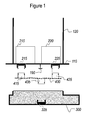
- FIGS 1-4 are not drawn to scale, and are only intended to schematically illustrate the interaction of the relevant components. For reasons of clarity, no hydraulic components are shown in the figures. Although various components will be understood to be sealingly attached to each other, the actual seals are not shown to keep the drawings clear. The skilled person will know where and how to apply conventional seals such as O-rings to obtain the required degree of sealing.
- Figure 1 represents a module consisting of a base plate 110 and a swirl pot 120 integrally moulded with the base plate 110.
- components 210 and 220 For reasons of clarity and without loss of generality, just two generic internal components of the module are schematically represented by components 210 and 220. Reference is made to WO 2009/007405 for a detailed description of a known module. Fluid communication between the inside and the outside of the tank is achieved by means of tubes passing through the base plate 110 (not shown).
- the base plate 110 is sometimes referred to in the art as the "flange".
- Module components 210 and 220 have respective connectors 215 and 225 protruding on the other side of the base plate 110.
- the interconnection apparatus comprises a substantially planar substrate 400 having a first side and a second side; at least one first connector 415, 425 arranged on the first side; and at least one second connector 435 arranged on the second side.
- the apparatus is adapted to compensate an alignment error of the complementary connectors intended to be mated with said at least one first connector 415, 425 and said at least one second connector 435.
- the complementary connectors are the connectors 215, 225 of the module; and the connector 335 of the external sub-assembly 300.
- the external sub-assembly 300 may take the form of one or more discrete components, or a number of such components pre-arranged in a housing (as illustrated). As the external sub-assembly 300 sometimes consist of a housing with pre-arranged components, which is mounted to cover the base plate, it is sometimes simply referred to in the art as a "cover”.
- the external sub-assembly 200 may include tubing that connects to a tube or nipple that passes through the base plate 110 (not shown).
- the external sub-assembly 300 is "external" in the sense that it comprises components that will reside outside the fluid containing volume of the vehicular fluid tank, after mounting of the assembly.
- the external sub-assembly 300 of the drawings will be considered to substantially consist of an electronic control unit.
- the relevant components are considered to be present in the shaded area, without being shown in detail.
- Electrical connections between terminals of the at least one first connector 415, 425 and terminals of the at least one second connector 435 may be provided by means of conductors arranged in or on said substrate 400 (not shown).
- the substrate 400 is preferably made of a material having an elastic modulus which is substantially lower than that of the connectors 415, 425, 435.
- the material may be a polymer, in particular an elastomer.
- the elastic modulus (Young's modulus) is preferably at least a factor 10 lower than that of the material of which the connectors 415, 425, 435 are made, more in particular at least a factor 100 lower. This ensures that mechanical stresses caused by initial misalignment of the connectors are absorbed by the substrate, and not by the connectors themselves.
- the substrate 400 may comprise a material that has appropriate thermal properties.
- the inventors have found that it may generally be desirable to conduct heat between components of the external sub-assembly and the contents of the vehicular fluid tank. For example, heat from an ECU could accelerate the process of thawing any frozen urea solution that may be present in the tank.
- the at least one first connector 415, 425 and/or the at least one second connector 435 are mounted onto the substrate 400 in a manner that allows a certain amount of relative movement. This avoids mechanical stresses in the connectors from being caused by initial misalignment of these connectors.
- the possible relative movement extends over a distance of at least 100 micrometer, more preferably at least 500 micrometer.
- the connectors 415, 425, 435 of the interconnection apparatus are provided with chamfered edges, which serve as guiding means for guiding the complementary connectors 215, 225; 335 into a connecting position during the coupling process.
- Spacers such as the exemplary spacer 190 shown in Figure 1 may be used to limit the deformation of the substrate 400 during the assembly process. They may be provided on the interconnection apparatus (not shown) or on the respective parts to be interconnected. The illustrated spacer 190 is placed such as to avoid excessive deformation of the substrate 400 during coupling of the external sub-assembly 300, which will place a certain amount of pressure on the second connector 435.
- Dashed arrows indicate the way in which the interconnection apparatus can be coupled with the module, by mating the first connectors 415, 425 of the interconnection apparatus with the complementary connectors 215, 225 of the module. At this point, there may be a certain misalignment between the connectors of the interconnection apparatus and their counterparts on the module, due to manufacturing tolerances of the module (this misalignment is not shown).
- the interconnection apparatus has been coupled with the module; i.e., the first connectors 415, 425 of the interconnection apparatus have been coupled with the complementary connectors 215, 225 of the module.
- the interconnection apparatus (in particular, the substrate 400) has absorbed any misalignment between the complementary connectors 215, 225 and their intended ideal positions.
- Dashed arrows indicate the way in which the interconnection apparatus can be coupled with the external sub-assembly, by mating the second connector 435 of the interconnection apparatus with the complementary connectors 335 of the external sub-assembly. At this point, there may be a certain misalignment between the connector of the interconnection apparatus and its counterpart on the external sub-assembly, due to manufacturing tolerances of the external sub-assembly (this misalignment is not shown).
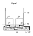
- the interconnection apparatus has further been coupled with the external sub-assembly 300; i.e., the second connector 435 of the interconnection apparatus has been coupled with the complementary connector 315 of the external sub-assembly 300.
- the interconnection apparatus (in particular, the substrate 400) has absorbed any misalignment between the complementary connector 435 and its intended ideal position.
- an assembly according to an embodiment of the present invention which can be mounted on a vehicular fluid tank, in particular in an SCR system of a motor vehicle.
- Figure 4 shows a variant of the assembly of Figure 3 , which is further equipped with a mounting ring 170.
- the module of Figure 4 may be attached to a tank wall (not shown) which has an opening with a mounting feature (not shown), in particular a thread or a cam lock. Attachment of the module takes place by arranging the base plate 110 over an opening in a tank wall, and securing a mounting ring 170 of the mason jar ring type over the based plate 110 so as to engage with the tank's thread.
- the mounting ring may be a component of a cam lock.
- a particular method of assembling an assembly includes attaching the external sub-assembly 300 to the base plate 110 with a mounting ring 170 interposed between them.
- the attaching takes place while the base plate 110 is not mounted to an opening of the tank.
- the size and shape of said external sub-assembly 300 and the base plate 110 prohibit the mounting ring 170 from being removed from between the external sub-assembly 300 and the base plate 110 after the attaching.
Landscapes
- Engineering & Computer Science (AREA)
- Chemical & Material Sciences (AREA)
- Chemical Kinetics & Catalysis (AREA)
- Combustion & Propulsion (AREA)
- Mechanical Engineering (AREA)
- General Engineering & Computer Science (AREA)
- Health & Medical Sciences (AREA)
- Toxicology (AREA)
- Manufacturing & Machinery (AREA)
- Exhaust Gas After Treatment (AREA)
Abstract
- a substantially planar substrate (400) having a first side and a second side;
- at least one first connector (415, 425) arranged on the first side; and
- at least one second connector (435) arranged on the second side.
Description
- The present invention pertains to electrical interconnection apparatus, in particular for use in vehicular fluid delivery systems such as systems for selective catalytic reduction of NOx in the exhaust gas of internal combustion engines.
- When two complex parts having multiple electrical connectors have to be coupled, small misalignments of the corresponding connectors of the respective parts can make the coupling more difficult or even impossible. This is of particular concern when the coupling is intended to take place in an automated environment, i.e. by robotic means.
- It is an object of embodiments of the present invention to at least partially overcome this problem.
- According to an aspect of the present invention, there is provided an interconnection apparatus comprising a substantially planar substrate having a first side and a second side; at least one first connector arranged on the first side; and at least one second connector arranged on the second side; the apparatus being adapted to compensate an alignment error of complementary connectors intended to be mated with the at least one first connector and the at least one second connector.
- It is an advantage of the present invention that the manufacturing tolerances of the parts to be interconnected can be absorbed by the interconnection apparatus, such that automated assembly can be ensured even in the presence of such tolerances (within certain limits). Moreover, the number of connectors on both sides need not be the same - in other words, the interconnection apparatus can act as an aggregator, combining the signals divided over multiple connectors on one side, into a smaller number of connectors (or even just one) on the other side. This further facilitates the assembly process.
- In an embodiment of the interconnection apparatus according to the present invention, the substrate is made of a material having an elastic modulus which is substantially lower than that of the connectors, in particular at least a factor 10 lower, more in particular at least a factor 100 lower.
- By choosing a relatively flexible material for the substrate, the interconnection apparatus will deform to absorb any misalignments, thus avoiding the introduction of mechanical stress into the actual connectors, which would otherwise risk damaging the conductive path of these connectors.
- In an embodiment of the interconnection apparatus according to the present invention, the at least one first connector and/or the at least one second connector are mounted onto the substrate in a manner that allows relative movement over a distance of at least 100 micrometer, preferably at least 500 micrometer.
- By allowing relative movement between the connectors, connector misalignments can be absorbed without risk of damaging the conductive path of these connectors.
- In an embodiment of the interconnection apparatus according to the present invention, the at least one first connector and/or the at least one second connector are provided with guiding means for guiding the complementary connectors into a connecting position. In a particular embodiment, the guiding means comprise chamfered or tapered edges.
- By providing guidance to the connector pairs, the connectors of the interconnection apparatus are allowed to move in a continuous manner from their resting position towards a position in which they absorb connector misalignments.
- In an embodiment of the interconnection apparatus according to the present invention, electrical connections are provided between terminals of the at least one first connector and terminals of the at least one second connector by means of conductors arranged in or on the substrate.
- According to an aspect of the present invention, there is provided an assembly comprising a delivery module for a vehicular fluid tank, an interconnection apparatus as described above, and an electronic control unit, each of the delivery module and the electronic control unit being equipped with at least of one of the complementary connectors, wherein the delivery module is coupled to the interconnection apparatus by means of the at least one first connector, and wherein the electronic control unit is coupled to the interconnection apparatus by means of the at least one second connector.
- According to an aspect of the present invention, there is provided a motor vehicle equipped with an assembly as described above.
- According to an aspect of the present invention, there is provided a method of assembling an assembly as described above, the method comprising: coupling an interconnection apparatus as described above to the delivery module, by coupling the at least one first connector to the complementary connector provided on the module; and coupling the electronic control unit to the interconnection apparatus by coupling the complementary connector provided on the electronic control unit to the at least one second connector.
- In the case of a delivery module for a vehicular fluid tank, such as a urea solution delivery module in a system for selective catalytic reduction (SCR) of NOx in engine exhaust gases, it is desirable to provide controllers for the active components of the module, for instance in the form of an electronic control unit (ECU), directly below the base plate. It is desirable to achieve interconnection between the delivery module and the controlling logic in an automated environment. The housing of the controlling logic and the module are mechanically aligned by means of guiding elements, such as protrusions and complementary recesses. Due to manufacturing tolerances, a correct mechanical alignment of the parts as such does not necessarily imply perfect alignment of the respective connectors of these parts. Thus, the interconnection apparatus of the present invention is particularly useful in this context.
- International patent application publication
WO 2007/141312 A1 in the name of the present applicant discloses a system for storing an internal combustion engine exhaust gas liquid additive, the said system comprising a tank for storing the additive and an "immersed" baseplate positioned through an opening made in the bottom wall of the tank, the said baseplate comprising at least one orifice through which a system for injecting the said additive into the exhaust gases can be fed, and also incorporating at least one other active component of the storage system and/or of the injection system. The baseplate may particularly be assembled with the opening in the tank using a ring-nut system screwed onto a thread on the tank side. - International patent application publication
WO 2009/007405 A1 in the name of the present applicant discloses a supply system for a liquid comprising a liquid tank, a supply line, a pump, a filter and a device that makes it possible to purge the line, pump and filter and that comprises a non-return device preventing liquid from entering into these elements once they have been purged. In this system, the pump, filter and non-return device are combined in a compact module, the filter at least partly surrounding the pump and the non-return device being an integral part of a common housing that surrounds the filter and at least one part of the pump. The tank may be equipped with a base plate or mounting plate which is a flattened part intended to block off an opening in its lower wall. This base plate may integrate the pump/filter/non-return device module. This is understood to mean that this module is either attached to this base plate or produced at least partly from one piece with this base plate. - It is a disadvantage of the ring-nut system that it constrains the spatial extent of any components that are pre-assembled on the bottom side (i.e., the side facing outwards from the tank) of the flange (hereinafter collectively referred to as the "cover"). This constraint is present because the ring has to be able to pass over the preassembled structure in order to reach its counterpart on the tank (i.e., the thread on surrounding the opening in the tank).
- In an embodiment of the method according to the present invention, the module is supported by a base plate suitable for being sealingly mounted onto an opening of a vehicular fluid tank, and the electronic control unit is comprised in an external sub-assembly, the method including attaching the external sub-assembly to the base plate with a mounting ring interposed between them, the attaching takes place while the base plate is not mounted onto the opening of the tank, and the size and shape of the external sub-assembly and the base plate prohibit the mounting ring from being removed from between the external sub-assembly and the base plate after the attaching.
- This embodiment is based inter alia on the insight of the inventor that the geometric constraints resting on the external sub-assembly due to the fact that the mounting ring must be able to pass over it afterwards, can be avoided by preassembling the base plate and the external sub-assembly with the mounting ring in between.
- It is a further advantage of this method that the leak-tightness and/or electrical connectivity of the assembly can be tested before the assembly is mounted onto a vehicle.
- The vehicular fluid tank may be a tank for a reducing agent used in selective catalytic reduction of engine exhaust gases. In particular, the vehicular fluid tank may be a tank for an aquous urea solution (such as the solutions commercially available under the trademarks AdBlue and Denoxium). Alternatively, the vehicular fluid tank may be a fuel tank. Still alternatively, the vehicular fluid tank may be a tank for storing liquids such as coolant, windscreen washer fluid, or oil.
- These and other aspects and advantages of the present invention will now be described in more detail with reference to the accompanying drawings, in which:
-
Figure 1 schematically represents an interconnection apparatus according to an embodiment of the present invention, prior to coupling to a vehicular fluid delivery module and an external sub-assembly; -
Figure 2 schematically represents the interconnection apparatus ofFigure 1 , coupled to the vehicular fluid delivery module, but prior to coupling to the external sub-assembly; -
Figure 3 schematically represents the interconnection apparatus ofFigure 1 , coupled to the vehicular fluid delivery module and the external sub-assembly; and -
Figure 4 schematically represents a variant of the assembly ofFigure 3 , wherein a coupling ring is interposed between the base plate of the delivery module and the external sub-assembly. -
Figures 1-4 are not drawn to scale, and are only intended to schematically illustrate the interaction of the relevant components. For reasons of clarity, no hydraulic components are shown in the figures. Although various components will be understood to be sealingly attached to each other, the actual seals are not shown to keep the drawings clear. The skilled person will know where and how to apply conventional seals such as O-rings to obtain the required degree of sealing. -
Figure 1 represents a module consisting of abase plate 110 and aswirl pot 120 integrally moulded with thebase plate 110. For reasons of clarity and without loss of generality, just two generic internal components of the module are schematically represented bycomponents WO 2009/007405 for a detailed description of a known module. Fluid communication between the inside and the outside of the tank is achieved by means of tubes passing through the base plate 110 (not shown). - The
base plate 110 is sometimes referred to in the art as the "flange". -
Module components respective connectors base plate 110. - The interconnection apparatus comprises a substantially
planar substrate 400 having a first side and a second side; at least onefirst connector second connector 435 arranged on the second side. The apparatus is adapted to compensate an alignment error of the complementary connectors intended to be mated with said at least onefirst connector second connector 435. In the illustrated case, the complementary connectors are theconnectors connector 335 of theexternal sub-assembly 300. - The
external sub-assembly 300 may take the form of one or more discrete components, or a number of such components pre-arranged in a housing (as illustrated). As theexternal sub-assembly 300 sometimes consist of a housing with pre-arranged components, which is mounted to cover the base plate, it is sometimes simply referred to in the art as a "cover". The external sub-assembly 200 may include tubing that connects to a tube or nipple that passes through the base plate 110 (not shown). Theexternal sub-assembly 300 is "external" in the sense that it comprises components that will reside outside the fluid containing volume of the vehicular fluid tank, after mounting of the assembly. - Without loss of generality, the
external sub-assembly 300 of the drawings will be considered to substantially consist of an electronic control unit. The relevant components are considered to be present in the shaded area, without being shown in detail. - Without loss of generality, two
first connectors second connector 435 are shown. - Electrical connections between terminals of the at least one
first connector second connector 435 may be provided by means of conductors arranged in or on said substrate 400 (not shown). - The
substrate 400 is preferably made of a material having an elastic modulus which is substantially lower than that of theconnectors connectors - The
substrate 400 may comprise a material that has appropriate thermal properties. In particular, the inventors have found that it may generally be desirable to conduct heat between components of the external sub-assembly and the contents of the vehicular fluid tank. For example, heat from an ECU could accelerate the process of thawing any frozen urea solution that may be present in the tank. Thus, it may be advantageous to include a material with good thermal conductivity in thesubstrate 400. - Preferably, the at least one
first connector second connector 435 are mounted onto thesubstrate 400 in a manner that allows a certain amount of relative movement. This avoids mechanical stresses in the connectors from being caused by initial misalignment of these connectors. Preferably, the possible relative movement extends over a distance of at least 100 micrometer, more preferably at least 500 micrometer. - It can be seen in the figures that the
connectors complementary connectors - Spacers, such as the
exemplary spacer 190 shown inFigure 1 may be used to limit the deformation of thesubstrate 400 during the assembly process. They may be provided on the interconnection apparatus (not shown) or on the respective parts to be interconnected. The illustratedspacer 190 is placed such as to avoid excessive deformation of thesubstrate 400 during coupling of theexternal sub-assembly 300, which will place a certain amount of pressure on thesecond connector 435. - Dashed arrows indicate the way in which the interconnection apparatus can be coupled with the module, by mating the
first connectors complementary connectors - In
Figure 2 , the interconnection apparatus has been coupled with the module; i.e., thefirst connectors complementary connectors complementary connectors - Dashed arrows indicate the way in which the interconnection apparatus can be coupled with the external sub-assembly, by mating the
second connector 435 of the interconnection apparatus with thecomplementary connectors 335 of the external sub-assembly. At this point, there may be a certain misalignment between the connector of the interconnection apparatus and its counterpart on the external sub-assembly, due to manufacturing tolerances of the external sub-assembly (this misalignment is not shown). - In
Figure 3 , the interconnection apparatus has further been coupled with theexternal sub-assembly 300; i.e., thesecond connector 435 of the interconnection apparatus has been coupled with the complementary connector 315 of theexternal sub-assembly 300. Again, the interconnection apparatus (in particular, the substrate 400) has absorbed any misalignment between thecomplementary connector 435 and its intended ideal position. - Thus is formed an assembly according to an embodiment of the present invention, which can be mounted on a vehicular fluid tank, in particular in an SCR system of a motor vehicle.
-
Figure 4 shows a variant of the assembly ofFigure 3 , which is further equipped with a mountingring 170. - The module of
Figure 4 may be attached to a tank wall (not shown) which has an opening with a mounting feature (not shown), in particular a thread or a cam lock. Attachment of the module takes place by arranging thebase plate 110 over an opening in a tank wall, and securing a mountingring 170 of the mason jar ring type over the basedplate 110 so as to engage with the tank's thread. Alternatively, the mounting ring may be a component of a cam lock. - Thus, a particular method of assembling an assembly according to an embodiment of the present invention includes attaching the
external sub-assembly 300 to thebase plate 110 with a mountingring 170 interposed between them. The attaching takes place while thebase plate 110 is not mounted to an opening of the tank. The size and shape of saidexternal sub-assembly 300 and thebase plate 110 prohibit the mountingring 170 from being removed from between theexternal sub-assembly 300 and thebase plate 110 after the attaching. - While the invention has been described hereinabove with reference to separate system and method embodiments, this was done for clarifying purposes only. The skilled person will appreciate that features described in connection with the system or the method alone, can also be applied to the method or the system, respectively, with the same technical effects and advantages. Furthermore, the scope of the invention is not limited to these embodiments, but is defined by the accompanying claims.
Claims (10)
- An interconnection apparatus comprising:- a substantially planar substrate (400) having a first side and a second side;- at least one first connector (415, 425) arranged on said first side; and- at least one second connector (435) arranged on said second side;said apparatus being adapted to compensate an alignment error of complementary connectors (215, 225; 335) intended to be mated with said at least one first connector (415, 425) and said at least one second connector (435).
- The interconnection apparatus according to claim 1, wherein said substrate (400) is made of a material having an elastic modulus which is substantially lower than that of the connectors (415, 425, 435), in particular at least a factor 10 lower, more in particular at least a factor 100 lower.
- The interconnection apparatus according to claim 1 or claim 2, wherein said at least one first connector (415, 425) and/or said at least one second connector (435) are mounted onto said substrate (400) in a manner that allows relative movement over a distance of at least 100 micrometer, preferably at least 500 micrometer.
- The interconnection apparatus according to any of the preceding claims, wherein said at least one first connector (415, 425) and/or said at least one second connector (435) are provided with guiding means for guiding said complementary connectors (215, 225; 335) into a connecting position.
- The interconnection apparatus according to any of the preceding claims, wherein said guiding means comprise chamfered or tapered edges.
- The interconnection apparatus according to any of the preceding claims, wherein electrical connections are provided between terminals of said at least one first connector (415, 425) and terminals of said at least one second connector (435) by means of conductors arranged in or on said substrate (400).
- An assembly comprising a delivery module (110, 120) for a vehicular fluid tank, an interconnection apparatus according to any of the preceding claims, and an electronic control unit (300),
each of said delivery module (110, 120) and said electronic control unit (300) being equipped with at least of one of said complementary connectors (215, 225; 335),
wherein said delivery module (110, 120) is coupled to said interconnection apparatus by means of said at least one first connector (415, 425), and wherein said electronic control unit (300) is coupled to said interconnection apparatus by means of said at least one second connector (435). - A motor vehicle equipped with an assembly according to claim 7.
- A method of assembling an assembly according to claim 7, the method comprising:- coupling an interconnection apparatus according to any of claims 1-6 to said delivery module (110, 120), by coupling said at least one first connector (415, 425) to said complementary connector (215, 225) provided on said module (110, 120); and- coupling said electronic control unit (300) to said interconnection apparatus by coupling said complementary connector (335) provided on said electronic control unit to said at least one second connector (435).
- The method according to claim 9, wherein said module (110, 120) is supported by a base plate (110) suitable for being sealingly mounted onto an opening of a vehicular fluid tank (100), and wherein said electronic control unit is comprised in an external sub-assembly (300), the method including attaching the external sub-assembly (300) to the base plate (110) with a mounting ring (170) interposed (610) between them,
wherein said attaching takes place while the base plate (110) is not mounted onto said opening of said tank (100),
and wherein the size and shape of said external sub-assembly (300) and said base plate (110) prohibit the mounting ring (170) from being removed from between said external sub-assembly (300) and said base plate (110) after said attaching.
Priority Applications (4)
| Application Number | Priority Date | Filing Date | Title |
|---|---|---|---|
| EP13183686.8A EP2846015B1 (en) | 2013-09-10 | 2013-09-10 | Assembly comprising a delivery module, an interconnection apparatus and an electronic control unit |
| PCT/EP2014/069321 WO2015036448A1 (en) | 2013-09-10 | 2014-09-10 | Interconnection apparatus and assembly comprising same |
| CN201480049212.7A CN105531454B (en) | 2013-09-10 | 2014-09-10 | Interconnect device and assembly comprising the same |
| US14/917,854 US9608371B2 (en) | 2013-09-10 | 2014-09-10 | Interconnection apparatus and assembly comprising same |
Applications Claiming Priority (1)
| Application Number | Priority Date | Filing Date | Title |
|---|---|---|---|
| EP13183686.8A EP2846015B1 (en) | 2013-09-10 | 2013-09-10 | Assembly comprising a delivery module, an interconnection apparatus and an electronic control unit |
Publications (2)
| Publication Number | Publication Date |
|---|---|
| EP2846015A1 true EP2846015A1 (en) | 2015-03-11 |
| EP2846015B1 EP2846015B1 (en) | 2017-05-24 |
Family
ID=49150804
Family Applications (1)
| Application Number | Title | Priority Date | Filing Date |
|---|---|---|---|
| EP13183686.8A Active EP2846015B1 (en) | 2013-09-10 | 2013-09-10 | Assembly comprising a delivery module, an interconnection apparatus and an electronic control unit |
Country Status (4)
| Country | Link |
|---|---|
| US (1) | US9608371B2 (en) |
| EP (1) | EP2846015B1 (en) |
| CN (1) | CN105531454B (en) |
| WO (1) | WO2015036448A1 (en) |
Families Citing this family (11)
| Publication number | Priority date | Publication date | Assignee | Title |
|---|---|---|---|---|
| PT3076073T (en) * | 2015-04-02 | 2017-06-09 | Schreder | IMPROVEMENTS IN OR RELATING TO MODULAR LUMINAIRE SETS |
| US10355383B2 (en) | 2017-03-13 | 2019-07-16 | Te Connectivity Corporation | Circuit card assemblies for a communication system |
| US11025004B2 (en) | 2017-08-09 | 2021-06-01 | TE Connectivity Services Gmbh | Circuit card assemblies for a communication system |
| US10553968B2 (en) | 2017-08-09 | 2020-02-04 | Te Connectivity Corporation | Electrical connector for a circuit card assembly of a communication system |
| US10411378B2 (en) | 2017-08-09 | 2019-09-10 | Te Connectivity Corporation | Circuit card assemblies for a communication system |
| US10381762B2 (en) * | 2017-09-29 | 2019-08-13 | Te Connectivity Corporation | Electrical connector for a circuit card assembly of a communication system |
| US10522925B2 (en) | 2017-09-29 | 2019-12-31 | Te Connectivity Corporation | Circuit card assemblies for a communication system |
| US10461470B2 (en) | 2018-02-14 | 2019-10-29 | Te Connectivity Corporation | Circuit card assemblies for a communication system |
| US10587064B1 (en) | 2019-01-23 | 2020-03-10 | Te Connectivity Corporation | Circuit card assemblies for a communication system |
| US10741950B1 (en) | 2019-03-14 | 2020-08-11 | Te Connectivity Corporation | Circuit card assemblies for a communication system |
| US11063391B2 (en) | 2019-10-11 | 2021-07-13 | TE Connectivity Services Gmbh | Circuit card assemblies for a communication system |
Citations (4)
| Publication number | Priority date | Publication date | Assignee | Title |
|---|---|---|---|---|
| US6790075B1 (en) * | 2003-07-18 | 2004-09-14 | Yun-Ching Sung | Serial ATA interface connector |
| WO2007141312A1 (en) | 2006-06-08 | 2007-12-13 | Inergy Automotive Systems Research (Société Anonyme) | Engine exhaust gas additive storage system |
| WO2009007405A1 (en) | 2007-07-10 | 2009-01-15 | Inergy Automotive Systems Research (Societe Anonyme) | System for supplying a liquid for a vehicle and integrated pump/filter module |
| DE102010062982A1 (en) * | 2010-12-14 | 2012-06-14 | Robert Bosch Gmbh | Tank module, liquid tank |
Family Cites Families (21)
| Publication number | Priority date | Publication date | Assignee | Title |
|---|---|---|---|---|
| US4850883A (en) * | 1987-05-21 | 1989-07-25 | Intel Corporation | High density flexible circuit connector |
| US4997377A (en) * | 1990-02-22 | 1991-03-05 | Amp Incorporated | Adaptor for computers |
| NL9200117A (en) * | 1992-01-22 | 1993-08-16 | Du Pont Nederland | SYSTEM AND CONNECTORS FOR THE ELECTRICAL CONNECTION OF COMPONENT BOARDS. |
| US5474458A (en) * | 1993-07-13 | 1995-12-12 | Fujitsu Limited | Interconnect carriers having high-density vertical connectors and methods for making the same |
| US5530623A (en) * | 1993-11-19 | 1996-06-25 | Ncr Corporation | High speed memory packaging scheme |
| JP3474655B2 (en) * | 1994-11-24 | 2003-12-08 | 株式会社ルネサスLsiデザイン | Emulator probe and debugging method using emulator probe |
| JP3589726B2 (en) * | 1995-01-31 | 2004-11-17 | 株式会社ルネサスソリューションズ | Emulator probe |
| JPH097715A (en) * | 1995-06-16 | 1997-01-10 | Canon Inc | Multilayer board design method and multilayer board |
| US6168459B1 (en) * | 1998-06-15 | 2001-01-02 | Seagate Technology Llc | Flex support and seal apparatus for a disc drive |
| US6144559A (en) * | 1999-04-08 | 2000-11-07 | Agilent Technologies | Process for assembling an interposer to probe dense pad arrays |
| US6491543B1 (en) * | 2000-06-22 | 2002-12-10 | Cray Inc. | Electrical circuit connector with tapered surface |
| US6347946B1 (en) * | 2000-11-08 | 2002-02-19 | Intel Corporation | Pin grid array socket |
| JP4131935B2 (en) * | 2003-02-18 | 2008-08-13 | 株式会社東芝 | Interface module, LSI package with interface module, and mounting method thereof |
| US6971887B1 (en) * | 2004-06-24 | 2005-12-06 | Intel Corporation | Multi-portion socket and related apparatuses |
| CN2731905Y (en) * | 2004-08-07 | 2005-10-05 | 鸿富锦精密工业(深圳)有限公司 | Connection face of circuit board |
| JP2007018785A (en) * | 2005-07-06 | 2007-01-25 | D D K Ltd | Connector |
| US7326092B2 (en) * | 2005-08-11 | 2008-02-05 | Tyco Electronics Corporation | Double ended guide pin assembly |
| FR2902136B1 (en) * | 2006-06-08 | 2008-08-08 | Inergy Automotive Systems Res | STORAGE SYSTEM FOR EXHAUST GAS ADDITIVE OF AN ENGINE |
| JP4496240B2 (en) * | 2007-08-10 | 2010-07-07 | 株式会社東芝 | LSI package with interface module |
| JP2011249076A (en) * | 2010-05-25 | 2011-12-08 | Fujitsu Component Ltd | Floating connector |
| US9076698B2 (en) * | 2012-10-23 | 2015-07-07 | Intel Corporation | Flexible package-to-socket interposer |
-
2013
- 2013-09-10 EP EP13183686.8A patent/EP2846015B1/en active Active
-
2014
- 2014-09-10 US US14/917,854 patent/US9608371B2/en active Active
- 2014-09-10 CN CN201480049212.7A patent/CN105531454B/en active Active
- 2014-09-10 WO PCT/EP2014/069321 patent/WO2015036448A1/en not_active Ceased
Patent Citations (4)
| Publication number | Priority date | Publication date | Assignee | Title |
|---|---|---|---|---|
| US6790075B1 (en) * | 2003-07-18 | 2004-09-14 | Yun-Ching Sung | Serial ATA interface connector |
| WO2007141312A1 (en) | 2006-06-08 | 2007-12-13 | Inergy Automotive Systems Research (Société Anonyme) | Engine exhaust gas additive storage system |
| WO2009007405A1 (en) | 2007-07-10 | 2009-01-15 | Inergy Automotive Systems Research (Societe Anonyme) | System for supplying a liquid for a vehicle and integrated pump/filter module |
| DE102010062982A1 (en) * | 2010-12-14 | 2012-06-14 | Robert Bosch Gmbh | Tank module, liquid tank |
Also Published As
| Publication number | Publication date |
|---|---|
| CN105531454B (en) | 2018-09-18 |
| US9608371B2 (en) | 2017-03-28 |
| CN105531454A (en) | 2016-04-27 |
| EP2846015B1 (en) | 2017-05-24 |
| US20160226190A1 (en) | 2016-08-04 |
| WO2015036448A1 (en) | 2015-03-19 |
Similar Documents
| Publication | Publication Date | Title |
|---|---|---|
| EP2846015B1 (en) | Assembly comprising a delivery module, an interconnection apparatus and an electronic control unit | |
| EP2538048B1 (en) | Reductant delivery unit for selective catalytic reduction | |
| US8464966B2 (en) | Delivery module for selective catalytic reduction | |
| EP2837785B1 (en) | Urea solution pumping module | |
| KR20200019781A (en) | Engine device | |
| US9121318B2 (en) | Delivery unit for delivering a liquid additive and motor vehicle having a delivery unit | |
| US9985378B2 (en) | Liquid extraction module, liquid tank | |
| US8413431B2 (en) | Tank assembly | |
| KR101855546B1 (en) | Engine exhaust gas additive storage tank | |
| US9587542B2 (en) | Metering module with high-temperature resistance | |
| US6598592B2 (en) | Fuel system including a fuel injector internally mounted to a fuel rail | |
| RU2650240C1 (en) | Liquid additive feeding device | |
| US8671915B2 (en) | Fuel pump module including a flange groove rod attachment | |
| KR101599666B1 (en) | Flange structure and pump module having the same | |
| US20250369383A1 (en) | Doser assembly with sensor assembly | |
| CN216866820U (en) | Selective catalytic reduction subsystem and vehicle exhaust aftertreatment system | |
| DE202008013048U1 (en) | Medium coupling with electrical connection | |
| CN214170650U (en) | Multi-section urea tank filling pipe and exhaust pipe combined structure for diesel vehicle | |
| CN214741887U (en) | Pump housing applied to urea pump | |
| KR101592815B1 (en) | Combination structure for pump and pump module having the same | |
| JP3714782B2 (en) | Engine harness mounting structure |
Legal Events
| Date | Code | Title | Description |
|---|---|---|---|
| 17P | Request for examination filed |
Effective date: 20130910 |
|
| AK | Designated contracting states |
Kind code of ref document: A1 Designated state(s): AL AT BE BG CH CY CZ DE DK EE ES FI FR GB GR HR HU IE IS IT LI LT LU LV MC MK MT NL NO PL PT RO RS SE SI SK SM TR |
|
| AX | Request for extension of the european patent |
Extension state: BA ME |
|
| PUAI | Public reference made under article 153(3) epc to a published international application that has entered the european phase |
Free format text: ORIGINAL CODE: 0009012 |
|
| R17P | Request for examination filed (corrected) |
Effective date: 20150904 |
|
| RBV | Designated contracting states (corrected) |
Designated state(s): AL AT BE BG CH CY CZ DE DK EE ES FI FR GB GR HR HU IE IS IT LI LT LU LV MC MK MT NL NO PL PT RO RS SE SI SK SM TR |
|
| 17Q | First examination report despatched |
Effective date: 20160428 |
|
| RIC1 | Information provided on ipc code assigned before grant |
Ipc: H01R 43/26 20060101ALI20161109BHEP Ipc: F01N 3/20 20060101AFI20161109BHEP Ipc: H01R 13/631 20060101ALI20161109BHEP Ipc: F01N 13/18 20100101ALI20161109BHEP Ipc: H01R 13/00 20060101ALI20161109BHEP |
|
| GRAP | Despatch of communication of intention to grant a patent |
Free format text: ORIGINAL CODE: EPIDOSNIGR1 |
|
| INTG | Intention to grant announced |
Effective date: 20161221 |
|
| GRAS | Grant fee paid |
Free format text: ORIGINAL CODE: EPIDOSNIGR3 |
|
| GRAA | (expected) grant |
Free format text: ORIGINAL CODE: 0009210 |
|
| AK | Designated contracting states |
Kind code of ref document: B1 Designated state(s): AL AT BE BG CH CY CZ DE DK EE ES FI FR GB GR HR HU IE IS IT LI LT LU LV MC MK MT NL NO PL PT RO RS SE SI SK SM TR |
|
| REG | Reference to a national code |
Ref country code: GB Ref legal event code: FG4D |
|
| REG | Reference to a national code |
Ref country code: CH Ref legal event code: EP |
|
| REG | Reference to a national code |
Ref country code: IE Ref legal event code: FG4D |
|
| REG | Reference to a national code |
Ref country code: AT Ref legal event code: REF Ref document number: 896133 Country of ref document: AT Kind code of ref document: T Effective date: 20170615 |
|
| REG | Reference to a national code |
Ref country code: DE Ref legal event code: R096 Ref document number: 602013021475 Country of ref document: DE |
|
| REG | Reference to a national code |
Ref country code: FR Ref legal event code: PLFP Year of fee payment: 5 |
|
| REG | Reference to a national code |
Ref country code: NL Ref legal event code: MP Effective date: 20170524 |
|
| REG | Reference to a national code |
Ref country code: LT Ref legal event code: MG4D |
|
| REG | Reference to a national code |
Ref country code: AT Ref legal event code: MK05 Ref document number: 896133 Country of ref document: AT Kind code of ref document: T Effective date: 20170524 |
|
| PG25 | Lapsed in a contracting state [announced via postgrant information from national office to epo] |
Ref country code: GR Free format text: LAPSE BECAUSE OF FAILURE TO SUBMIT A TRANSLATION OF THE DESCRIPTION OR TO PAY THE FEE WITHIN THE PRESCRIBED TIME-LIMIT Effective date: 20170825 Ref country code: FI Free format text: LAPSE BECAUSE OF FAILURE TO SUBMIT A TRANSLATION OF THE DESCRIPTION OR TO PAY THE FEE WITHIN THE PRESCRIBED TIME-LIMIT Effective date: 20170524 Ref country code: HR Free format text: LAPSE BECAUSE OF FAILURE TO SUBMIT A TRANSLATION OF THE DESCRIPTION OR TO PAY THE FEE WITHIN THE PRESCRIBED TIME-LIMIT Effective date: 20170524 Ref country code: NO Free format text: LAPSE BECAUSE OF FAILURE TO SUBMIT A TRANSLATION OF THE DESCRIPTION OR TO PAY THE FEE WITHIN THE PRESCRIBED TIME-LIMIT Effective date: 20170824 Ref country code: ES Free format text: LAPSE BECAUSE OF FAILURE TO SUBMIT A TRANSLATION OF THE DESCRIPTION OR TO PAY THE FEE WITHIN THE PRESCRIBED TIME-LIMIT Effective date: 20170524 Ref country code: LT Free format text: LAPSE BECAUSE OF FAILURE TO SUBMIT A TRANSLATION OF THE DESCRIPTION OR TO PAY THE FEE WITHIN THE PRESCRIBED TIME-LIMIT Effective date: 20170524 Ref country code: AT Free format text: LAPSE BECAUSE OF FAILURE TO SUBMIT A TRANSLATION OF THE DESCRIPTION OR TO PAY THE FEE WITHIN THE PRESCRIBED TIME-LIMIT Effective date: 20170524 |
|
| PG25 | Lapsed in a contracting state [announced via postgrant information from national office to epo] |
Ref country code: SE Free format text: LAPSE BECAUSE OF FAILURE TO SUBMIT A TRANSLATION OF THE DESCRIPTION OR TO PAY THE FEE WITHIN THE PRESCRIBED TIME-LIMIT Effective date: 20170524 Ref country code: LV Free format text: LAPSE BECAUSE OF FAILURE TO SUBMIT A TRANSLATION OF THE DESCRIPTION OR TO PAY THE FEE WITHIN THE PRESCRIBED TIME-LIMIT Effective date: 20170524 Ref country code: IS Free format text: LAPSE BECAUSE OF FAILURE TO SUBMIT A TRANSLATION OF THE DESCRIPTION OR TO PAY THE FEE WITHIN THE PRESCRIBED TIME-LIMIT Effective date: 20170924 Ref country code: NL Free format text: LAPSE BECAUSE OF FAILURE TO SUBMIT A TRANSLATION OF THE DESCRIPTION OR TO PAY THE FEE WITHIN THE PRESCRIBED TIME-LIMIT Effective date: 20170524 Ref country code: RS Free format text: LAPSE BECAUSE OF FAILURE TO SUBMIT A TRANSLATION OF THE DESCRIPTION OR TO PAY THE FEE WITHIN THE PRESCRIBED TIME-LIMIT Effective date: 20170524 Ref country code: BG Free format text: LAPSE BECAUSE OF FAILURE TO SUBMIT A TRANSLATION OF THE DESCRIPTION OR TO PAY THE FEE WITHIN THE PRESCRIBED TIME-LIMIT Effective date: 20170824 |
|
| PG25 | Lapsed in a contracting state [announced via postgrant information from national office to epo] |
Ref country code: RO Free format text: LAPSE BECAUSE OF FAILURE TO SUBMIT A TRANSLATION OF THE DESCRIPTION OR TO PAY THE FEE WITHIN THE PRESCRIBED TIME-LIMIT Effective date: 20170524 Ref country code: SK Free format text: LAPSE BECAUSE OF FAILURE TO SUBMIT A TRANSLATION OF THE DESCRIPTION OR TO PAY THE FEE WITHIN THE PRESCRIBED TIME-LIMIT Effective date: 20170524 Ref country code: EE Free format text: LAPSE BECAUSE OF FAILURE TO SUBMIT A TRANSLATION OF THE DESCRIPTION OR TO PAY THE FEE WITHIN THE PRESCRIBED TIME-LIMIT Effective date: 20170524 Ref country code: DK Free format text: LAPSE BECAUSE OF FAILURE TO SUBMIT A TRANSLATION OF THE DESCRIPTION OR TO PAY THE FEE WITHIN THE PRESCRIBED TIME-LIMIT Effective date: 20170524 Ref country code: CZ Free format text: LAPSE BECAUSE OF FAILURE TO SUBMIT A TRANSLATION OF THE DESCRIPTION OR TO PAY THE FEE WITHIN THE PRESCRIBED TIME-LIMIT Effective date: 20170524 |
|
| REG | Reference to a national code |
Ref country code: DE Ref legal event code: R097 Ref document number: 602013021475 Country of ref document: DE |
|
| PG25 | Lapsed in a contracting state [announced via postgrant information from national office to epo] |
Ref country code: IT Free format text: LAPSE BECAUSE OF FAILURE TO SUBMIT A TRANSLATION OF THE DESCRIPTION OR TO PAY THE FEE WITHIN THE PRESCRIBED TIME-LIMIT Effective date: 20170524 Ref country code: PL Free format text: LAPSE BECAUSE OF FAILURE TO SUBMIT A TRANSLATION OF THE DESCRIPTION OR TO PAY THE FEE WITHIN THE PRESCRIBED TIME-LIMIT Effective date: 20170524 Ref country code: SM Free format text: LAPSE BECAUSE OF FAILURE TO SUBMIT A TRANSLATION OF THE DESCRIPTION OR TO PAY THE FEE WITHIN THE PRESCRIBED TIME-LIMIT Effective date: 20170524 |
|
| PLBE | No opposition filed within time limit |
Free format text: ORIGINAL CODE: 0009261 |
|
| STAA | Information on the status of an ep patent application or granted ep patent |
Free format text: STATUS: NO OPPOSITION FILED WITHIN TIME LIMIT |
|
| REG | Reference to a national code |
Ref country code: CH Ref legal event code: PL |
|
| 26N | No opposition filed |
Effective date: 20180227 |
|
| GBPC | Gb: european patent ceased through non-payment of renewal fee |
Effective date: 20170910 |
|
| PG25 | Lapsed in a contracting state [announced via postgrant information from national office to epo] |
Ref country code: SI Free format text: LAPSE BECAUSE OF FAILURE TO SUBMIT A TRANSLATION OF THE DESCRIPTION OR TO PAY THE FEE WITHIN THE PRESCRIBED TIME-LIMIT Effective date: 20170524 Ref country code: MC Free format text: LAPSE BECAUSE OF FAILURE TO SUBMIT A TRANSLATION OF THE DESCRIPTION OR TO PAY THE FEE WITHIN THE PRESCRIBED TIME-LIMIT Effective date: 20170524 |
|
| REG | Reference to a national code |
Ref country code: IE Ref legal event code: MM4A |
|
| REG | Reference to a national code |
Ref country code: BE Ref legal event code: MM Effective date: 20170930 |
|
| PG25 | Lapsed in a contracting state [announced via postgrant information from national office to epo] |
Ref country code: LU Free format text: LAPSE BECAUSE OF NON-PAYMENT OF DUE FEES Effective date: 20170910 |
|
| PG25 | Lapsed in a contracting state [announced via postgrant information from national office to epo] |
Ref country code: LI Free format text: LAPSE BECAUSE OF NON-PAYMENT OF DUE FEES Effective date: 20170930 Ref country code: CH Free format text: LAPSE BECAUSE OF NON-PAYMENT OF DUE FEES Effective date: 20170930 Ref country code: GB Free format text: LAPSE BECAUSE OF NON-PAYMENT OF DUE FEES Effective date: 20170910 Ref country code: IE Free format text: LAPSE BECAUSE OF NON-PAYMENT OF DUE FEES Effective date: 20170910 |
|
| PG25 | Lapsed in a contracting state [announced via postgrant information from national office to epo] |
Ref country code: BE Free format text: LAPSE BECAUSE OF NON-PAYMENT OF DUE FEES Effective date: 20170930 |
|
| REG | Reference to a national code |
Ref country code: FR Ref legal event code: PLFP Year of fee payment: 6 |
|
| PG25 | Lapsed in a contracting state [announced via postgrant information from national office to epo] |
Ref country code: MT Free format text: LAPSE BECAUSE OF NON-PAYMENT OF DUE FEES Effective date: 20170910 |
|
| PG25 | Lapsed in a contracting state [announced via postgrant information from national office to epo] |
Ref country code: HU Free format text: LAPSE BECAUSE OF FAILURE TO SUBMIT A TRANSLATION OF THE DESCRIPTION OR TO PAY THE FEE WITHIN THE PRESCRIBED TIME-LIMIT; INVALID AB INITIO Effective date: 20130910 |
|
| PG25 | Lapsed in a contracting state [announced via postgrant information from national office to epo] |
Ref country code: CY Free format text: LAPSE BECAUSE OF FAILURE TO SUBMIT A TRANSLATION OF THE DESCRIPTION OR TO PAY THE FEE WITHIN THE PRESCRIBED TIME-LIMIT Effective date: 20170524 |
|
| PG25 | Lapsed in a contracting state [announced via postgrant information from national office to epo] |
Ref country code: MK Free format text: LAPSE BECAUSE OF FAILURE TO SUBMIT A TRANSLATION OF THE DESCRIPTION OR TO PAY THE FEE WITHIN THE PRESCRIBED TIME-LIMIT Effective date: 20170524 |
|
| PG25 | Lapsed in a contracting state [announced via postgrant information from national office to epo] |
Ref country code: TR Free format text: LAPSE BECAUSE OF FAILURE TO SUBMIT A TRANSLATION OF THE DESCRIPTION OR TO PAY THE FEE WITHIN THE PRESCRIBED TIME-LIMIT Effective date: 20170524 |
|
| PG25 | Lapsed in a contracting state [announced via postgrant information from national office to epo] |
Ref country code: PT Free format text: LAPSE BECAUSE OF FAILURE TO SUBMIT A TRANSLATION OF THE DESCRIPTION OR TO PAY THE FEE WITHIN THE PRESCRIBED TIME-LIMIT Effective date: 20170524 |
|
| PG25 | Lapsed in a contracting state [announced via postgrant information from national office to epo] |
Ref country code: AL Free format text: LAPSE BECAUSE OF FAILURE TO SUBMIT A TRANSLATION OF THE DESCRIPTION OR TO PAY THE FEE WITHIN THE PRESCRIBED TIME-LIMIT Effective date: 20170524 |
|
| P01 | Opt-out of the competence of the unified patent court (upc) registered |
Effective date: 20230515 |
|
| REG | Reference to a national code |
Ref country code: DE Ref legal event code: R081 Ref document number: 602013021475 Country of ref document: DE Owner name: OPMOBILITY C-POWER BELGIUM RESEARCH, BE Free format text: FORMER OWNER: INERGY AUTOMOTIVE SYSTEMS RESEARCH (SOCIETE ANONYME), BRUXELLES, BE |
|
| PGFP | Annual fee paid to national office [announced via postgrant information from national office to epo] |
Ref country code: DE Payment date: 20250919 Year of fee payment: 13 |
|
| PGFP | Annual fee paid to national office [announced via postgrant information from national office to epo] |
Ref country code: FR Payment date: 20250926 Year of fee payment: 13 |