EP2845957A1 - Outlet device for a sink - Google Patents
Outlet device for a sink Download PDFInfo
- Publication number
- EP2845957A1 EP2845957A1 EP14183141.2A EP14183141A EP2845957A1 EP 2845957 A1 EP2845957 A1 EP 2845957A1 EP 14183141 A EP14183141 A EP 14183141A EP 2845957 A1 EP2845957 A1 EP 2845957A1
- Authority
- EP
- European Patent Office
- Prior art keywords
- sink
- strainer
- valve
- control device
- plug
- Prior art date
- Legal status (The legal status is an assumption and is not a legal conclusion. Google has not performed a legal analysis and makes no representation as to the accuracy of the status listed.)
- Withdrawn
Links
- 230000001747 exhibiting effect Effects 0.000 claims abstract 2
- 238000004140 cleaning Methods 0.000 claims description 11
- 239000000463 material Substances 0.000 claims description 8
- 230000000284 resting effect Effects 0.000 claims description 5
- XLYOFNOQVPJJNP-UHFFFAOYSA-N water Substances O XLYOFNOQVPJJNP-UHFFFAOYSA-N 0.000 claims description 5
- 239000011343 solid material Substances 0.000 claims description 4
- 239000011345 viscous material Substances 0.000 claims description 3
- 239000010794 food waste Substances 0.000 description 4
- 238000010276 construction Methods 0.000 description 3
- 239000007788 liquid Substances 0.000 description 2
- 230000001419 dependent effect Effects 0.000 description 1
- 239000011346 highly viscous material Substances 0.000 description 1
- 238000012423 maintenance Methods 0.000 description 1
- 238000007790 scraping Methods 0.000 description 1
Images


Classifications
-
- E—FIXED CONSTRUCTIONS
- E03—WATER SUPPLY; SEWERAGE
- E03C—DOMESTIC PLUMBING INSTALLATIONS FOR FRESH WATER OR WASTE WATER; SINKS
- E03C1/00—Domestic plumbing installations for fresh water or waste water; Sinks
- E03C1/12—Plumbing installations for waste water; Basins or fountains connected thereto; Sinks
- E03C1/22—Outlet devices mounted in basins, baths, or sinks
- E03C1/23—Outlet devices mounted in basins, baths, or sinks with mechanical closure mechanisms
- E03C1/2304—Outlet devices mounted in basins, baths, or sinks with mechanical closure mechanisms the actuation force being transmitted to the plug via flexible elements, e.g. chain, Bowden cable
-
- E—FIXED CONSTRUCTIONS
- E03—WATER SUPPLY; SEWERAGE
- E03C—DOMESTIC PLUMBING INSTALLATIONS FOR FRESH WATER OR WASTE WATER; SINKS
- E03C1/00—Domestic plumbing installations for fresh water or waste water; Sinks
- E03C1/12—Plumbing installations for waste water; Basins or fountains connected thereto; Sinks
- E03C1/26—Object-catching inserts or similar devices for waste pipes or outlets
- E03C1/264—Separate sieves or similar object-catching inserts
-
- E—FIXED CONSTRUCTIONS
- E03—WATER SUPPLY; SEWERAGE
- E03C—DOMESTIC PLUMBING INSTALLATIONS FOR FRESH WATER OR WASTE WATER; SINKS
- E03C1/00—Domestic plumbing installations for fresh water or waste water; Sinks
- E03C1/12—Plumbing installations for waste water; Basins or fountains connected thereto; Sinks
- E03C1/22—Outlet devices mounted in basins, baths, or sinks
- E03C1/23—Outlet devices mounted in basins, baths, or sinks with mechanical closure mechanisms
- E03C2001/2311—Outlet devices mounted in basins, baths, or sinks with mechanical closure mechanisms the actuation force being magnetic or electromagnetic
Definitions
- Traditional kitchen sinks are provided with discharge with a strainer having a circular periphery and provided with a grip in the center of the strainer in order to retrieve it from the sink for cleaning and/or removal of food residues and similar, accumulated in the strainer.
- the strainer is combined with a plug to close the discharge in the sink. In a closed position, the strainer bears against the discharge opening in the sink. In order to drain the liquid content in the sink, the user grasps the grip in the center of the strainer and lifts the same a little bit out of the discharge opening, so that the strainer is located in an open position in the discharge opening.
- the strainer can be lifted totally out of the discharge opening to remove food residues, as mentioned above, from the strainer and possibly the sink, and perform cleaning of the same.
- a disadvantage of this construction is that the user must grip the strainer and touch food residues and similar, accumulated down in the strainer.
- DE 197 06 795 C1 describes a device at a discharge in a kitchen sink or similar.
- the device exhibits a bottom, walls and a valve arranged in a discharge formed in the bottom of the sink.
- a control device is arranged outside the sink and is connected with the valve to open the same.
- the discharge exhibits a strainer provided with recesses or openings to drain water but retain larger viscous or solid material when the valve is open.
- the strainer is formed with substantially right/even lateral edges viewed substantially perpendicular to the bottom plane of the sink, and is arranged detached from the sink and separate from the valve means, and is arranged in a recess in the bottom of the sink.
- the valve comprises a plug arranged under the strainer, and is formed with a periphery which is larger than or equal to the discharge opening in the bottom of the sink and is, in a closed position, arranged to bear sealingly against a land surface or seat in the bottom of the sink, whereby the control device by means of a force transmitting device is arranged to lift the valve from a closed position to an open position.
- the control device is not arranged to lift the valve further, and the operator must therefore guide the hand down into polluted water to grasp the strainer and lift it out of the sink.
- DE 296 03 146 U1 and EP 0 726 366 A1 disclose a similar construction, but here a control device is arranged outside the sink to open the valve. Neither here is the control device arranged to lift the valve further and push it out of the resting position.
- the present invention concerns a device at an outlet of a cleaning basin or similar, particularly a kitchen sink which exhibits a bottom, walls and a valve means arranged in a discharge opening formed in the bottom of the kitchen sink.
- a control device is located in a position outside the kitchen sink and is connected with the valve means to open the valve means.
- the discharge exhibits a strainer provided with recesses or openings to drain water but retain larger viscous or solid material when the valve is open, whereby the strainer is formed with substantially right lateral edges viewed substantially perpendicular to the bottom plane of the sink and is arranged detached from the sink and separate from the valve means and arranged in a recess in the bottom of the kitchen sink.
- the valve comprises a plug arranged under the strainer and is formed with a periphery larger than or equal to the discharge opening in the bottom of the sink and is, in a closing position, arranged to bear sealingly against a land surface or seat in the bottom of the sink, whereby the control device by means of a force transmitting device is arranged to lift the valve from a closed position to an open position.
- the plug is connected to a stem extending downwards from the plug in the discharge and contacts the force transmitting device comprising a lifting pin actuated by the control device to lift the valve means further and push it out of its resting position in the recess in the bottom of the sink, so that the strainer can be gripped by the hand of a person.
- the strainer is advantageously formed with a rectangular periphery and exhibits four right lateral edges.
- at least one of the right lateral edges of the strainer is provided with a brim of a softer material.
- the material is a wear resistant plastic material.
- the lifting pin is arranged pivotal about a shaft.
- the control device is connected mechanically to the lifting pin via a wire, to enable the valve to be opened by pressing the control device and make the lifting pin to contact the stem to push or pull the stem upwards and lift the plug out of the seat.
- the control device is provided with a return spring which is able to push the control device back to its starting position when no press force is exerted on the control device.
- the control device comprises one or more switches in the form of piezoelectric buttons integrated in the edge of the cleaning sink.
- the plug is located acentric to the strainer, so that only one side of the strainer is pushed upwards when the plug contacts the strainer from below.
- the strainer in a kitchen sink is arranged separate from the sink to enable detachment from the same, and formed separately from a stop valve in the kitchen sink.
- the valve is provided with a remote control device arranged adjacent to the sink and is connected, preferably mechanically, to a force transmitting device at the bottom of the sink to control valve position.
- the valve can be opened from a closed position to an open position to empty liquid from the sink, and further to a lifting position where the valve contacts the underside of the strainer and pushes the same out from its resting position in the bottom of the sink.
- the sink is formed with substantially right lateral edges substantially perpendicular to the bottom plane of the sink when the strainer rests within the same, particularly with a rectangular shape.
- the strainer is particularly provided with a brim of softer material, such as a wear resistant plastic material, to enable cleaning of the sink and adjacent areas by the strainer itself.
- An advantage of the present construction is that the user does not have to grip down into food residues and similar located down in the strainer, in order to lift the strainer out of the sink. Moreover, the strainer design provides a scraping tool to clean the bottom of the kitchen sink.
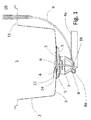
- FIG. 1 shows a schematic cross section through a kitchen sink 1 in a kitchen bench (not illustrated).
- the sink comprises walls 2 and a bottom 3 provided with a discharge 4 to drain wash water.
- a valve is provided in the bottom and comprises a plug 6 having a periphery which is larger than or equal to the opening 4 and is arranged to bear sealingly but releasable against a land surface 5 formed as a part of the bottom of the sink.
- the plug 6 is provided with a stem 7 extending downwards through the opening 4 in the sink and is supported by supporting means (not illustrated), so that the plug 6 and the valve stem 7 can be moved substantially vertically to bring the valve from a closed position to an open position.
- a force transmitting device 8 is arranged at the lower end of the stem 7 and exhibits a lifting pin 16 to contact the end of the stem 7 and push the plug upwards.
- the lifting pin 16 is supported pivotal about a shaft 8a and is connected to an operating device 10 via intermediate wire 9.
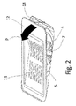
- Figure 2 shows the strainer 12 in perspective from above.
- the strainer exhibits a rectangular periphery having slit shaped recesses 13 to retain solid or highly viscous material.
- the strainer is arranged in a correspondingly formed rectangular recess 14 in the bottom 3 of the sink 1.
- Figure 2 shows a glimpse of parts of the land surface 5 for the plug 6 and the valve stem 7, including the discharge 4 in the bottom of the sink.
- figure 2 shows the strainer in a released position where the valve 6, 7 has pushed the strainer out of the resting position in the recess 14 in direction of the arrow P and ready to be gripped by the hand of a user.
- Figures 3a-3d show a highly schematic progress of opening of the valve and release of the strainer.
- Figure 3a shows the device in a closed position where the plug bears sealingly against the land surface 5 formed down within the recess 14 in the bottom 3 of the sink.
- Figure 3b shows the valve 6, 7 in an open position from where the lifting pin 16 is in contact with the valve stem 7 and has pushed the plug 6 up from closed position from the operating device (not shown).
- the lifting pin 16 is arranged pivotal about a shaft 8a.
- FIG. 5a and 5b show, very schematic, an example of a control device 10, here comprising a lid/control button 22 serving as a push button for the user.
- a shaft 23 is arranged, provided with a return spring 24.
- the control device (10) is connected mechanically to the lifting pin (16) via a wire (9, 18), to enable the valve (6, 7) to be opened by pressing the control device (10) and make the lifting pin (16) to contact the stem (7) to push or pull the stem upwards and lift the plug (6) out of the seat (5).
- the return spring (24) is able to push the control device (10) back to its starting position when no press force is exerted on the control device (10).
- control device comprises a middle piece 25 to assemble the control button 22 described above and the wire including accessories as described below.
- the (lowermost) end 25 of the middle piece is provided with internal threads.
- the upper end of the wire 18 is adapted within a guiding tube 26 and a nut 27 with internal threads to be screwed fixedly to the end part of the middle piece 25 together with the control button, and attached within the surface 11 of a kitchen bench aside the kitchen sink (see Fig. 1 ).
- the example described above shows a mechanical control of the valve.
- an electro-mechanical control of the valve is also conceivable, where an actuator is arranged in the form of an electro-mechanical device at the valve under the sink, which is controlled by control signals from switches in a piezoelectric push-button panel at the upper rim of the sink.
- the plug (6) is advantageously located acentric to the strainer (12), so that only one side of the strainer is pushed upwards when the plug contacts the strainer from below. This arrangement simplifies gripping of the strainer by the hand of a user.
Landscapes
- Engineering & Computer Science (AREA)
- Environmental & Geological Engineering (AREA)
- Health & Medical Sciences (AREA)
- Life Sciences & Earth Sciences (AREA)
- Hydrology & Water Resources (AREA)
- Public Health (AREA)
- Water Supply & Treatment (AREA)
- Mechanical Engineering (AREA)
- Sink And Installation For Waste Water (AREA)
- Non-Portable Lighting Devices Or Systems Thereof (AREA)
- Domestic Plumbing Installations (AREA)
Abstract
Device at an outlet of a kitchen sink (1), exhibiting a bottom (3), walls (2) and a vertically adjustable valve (6, 7) arranged in a discharge (4) in the bottom (3). A control device (10) is located in a position outside the kitchen sink (2, 3) and connected with the valve (6, 7) to control the valve (6, 7). A rectangular strainer (12) provided with recesses or openings (13) is arranged, detached from the sink (1) and separate from the valve (6, 7), in a recess (14) in the bottom (3) of the sink (1). A force transmitting device (8, 16) is, via the control device (8, 16), connected to the valve (6, 7) via a lifting pin (16) arranged to lift the valve (6, 7) from a closed valve position, to an open valve position, and further to a position where the strainer (12) is pushed out of the recess (14) in the sink so that the strainer (12) can be gripped by the hand (15) of a person.
Description
- Traditional kitchen sinks are provided with discharge with a strainer having a circular periphery and provided with a grip in the center of the strainer in order to retrieve it from the sink for cleaning and/or removal of food residues and similar, accumulated in the strainer. Usually, the strainer is combined with a plug to close the discharge in the sink. In a closed position, the strainer bears against the discharge opening in the sink. In order to drain the liquid content in the sink, the user grasps the grip in the center of the strainer and lifts the same a little bit out of the discharge opening, so that the strainer is located in an open position in the discharge opening. The strainer can be lifted totally out of the discharge opening to remove food residues, as mentioned above, from the strainer and possibly the sink, and perform cleaning of the same. A disadvantage of this construction is that the user must grip the strainer and touch food residues and similar, accumulated down in the strainer.
- Remotely operated discharges for kitchen sinks and similar, are known from the prior art. One example is
CA , which describes a remote operating device for a discharge fitting. The starting point of the invention described there is that known solutions, where the strainer is opened by pressing a button and closed by releasing the press force on the button; fail to provide a safe closure of the discharge. The object of the Canadian device is to provide a remote control device offering simplified maintenance of the same. In these prior art discharge devices, the strainer is fixedly connected to the remote control mechanism.patent publication 2 797 522 - An example of integrated means for cleaning sinks is described in
WO 04/04058 -
DE 197 06 795 C1 describes a device at a discharge in a kitchen sink or similar. The device exhibits a bottom, walls and a valve arranged in a discharge formed in the bottom of the sink. A control device is arranged outside the sink and is connected with the valve to open the same. The discharge exhibits a strainer provided with recesses or openings to drain water but retain larger viscous or solid material when the valve is open. Moreover, the strainer is formed with substantially right/even lateral edges viewed substantially perpendicular to the bottom plane of the sink, and is arranged detached from the sink and separate from the valve means, and is arranged in a recess in the bottom of the sink. The valve comprises a plug arranged under the strainer, and is formed with a periphery which is larger than or equal to the discharge opening in the bottom of the sink and is, in a closed position, arranged to bear sealingly against a land surface or seat in the bottom of the sink, whereby the control device by means of a force transmitting device is arranged to lift the valve from a closed position to an open position. However, the control device is not arranged to lift the valve further, and the operator must therefore guide the hand down into polluted water to grasp the strainer and lift it out of the sink. - For example
DE 296 03 146 U1 andEP 0 726 366 A1 disclose a similar construction, but here a control device is arranged outside the sink to open the valve. Neither here is the control device arranged to lift the valve further and push it out of the resting position. - Other examples of related prior art within this technical field are
DE 20 2012 011 181 U1EP 2 369 071 A1EP 1961874 A2 for discharge, control device with wire and return spring, including use of electric actuator, respectively. - An object of the invention is to provide a discharge in a cleaning basin where the strainer can be released from the basin without gripping the strainer. Another object of the invention is to provide a discharge in a kitchen sink which enables cleaning of the sink without the need for additional tools.
- These objects are achieved by a device at a discharge in a cleaning basin in accordance with
patent claim 1. Further advantageous features appear from the dependent patent claims. - The present invention concerns a device at an outlet of a cleaning basin or similar, particularly a kitchen sink which exhibits a bottom, walls and a valve means arranged in a discharge opening formed in the bottom of the kitchen sink. A control device is located in a position outside the kitchen sink and is connected with the valve means to open the valve means. Moreover, the discharge exhibits a strainer provided with recesses or openings to drain water but retain larger viscous or solid material when the valve is open, whereby the strainer is formed with substantially right lateral edges viewed substantially perpendicular to the bottom plane of the sink and is arranged detached from the sink and separate from the valve means and arranged in a recess in the bottom of the kitchen sink. The valve comprises a plug arranged under the strainer and is formed with a periphery larger than or equal to the discharge opening in the bottom of the sink and is, in a closing position, arranged to bear sealingly against a land surface or seat in the bottom of the sink, whereby the control device by means of a force transmitting device is arranged to lift the valve from a closed position to an open position. In accordance with the invention, the plug is connected to a stem extending downwards from the plug in the discharge and contacts the force transmitting device comprising a lifting pin actuated by the control device to lift the valve means further and push it out of its resting position in the recess in the bottom of the sink, so that the strainer can be gripped by the hand of a person.
- The strainer is advantageously formed with a rectangular periphery and exhibits four right lateral edges. Preferably, at least one of the right lateral edges of the strainer is provided with a brim of a softer material. In a preferred embodiment, the material is a wear resistant plastic material.
- Moreover, the lifting pin is arranged pivotal about a shaft. The control device is connected mechanically to the lifting pin via a wire, to enable the valve to be opened by pressing the control device and make the lifting pin to contact the stem to push or pull the stem upwards and lift the plug out of the seat. The control device is provided with a return spring which is able to push the control device back to its starting position when no press force is exerted on the control device. In an alternative embodiment, the control device comprises one or more switches in the form of piezoelectric buttons integrated in the edge of the cleaning sink.
- In yet an alternative embodiment, the plug is located acentric to the strainer, so that only one side of the strainer is pushed upwards when the plug contacts the strainer from below.
- Accordingly, in accordance with the invention, the strainer in a kitchen sink is arranged separate from the sink to enable detachment from the same, and formed separately from a stop valve in the kitchen sink. Moreover, the valve is provided with a remote control device arranged adjacent to the sink and is connected, preferably mechanically, to a force transmitting device at the bottom of the sink to control valve position. In this way, the valve can be opened from a closed position to an open position to empty liquid from the sink, and further to a lifting position where the valve contacts the underside of the strainer and pushes the same out from its resting position in the bottom of the sink. Moreover, the sink is formed with substantially right lateral edges substantially perpendicular to the bottom plane of the sink when the strainer rests within the same, particularly with a rectangular shape. The strainer is particularly provided with a brim of softer material, such as a wear resistant plastic material, to enable cleaning of the sink and adjacent areas by the strainer itself.
- An advantage of the present construction is that the user does not have to grip down into food residues and similar located down in the strainer, in order to lift the strainer out of the sink. Moreover, the strainer design provides a scraping tool to clean the bottom of the kitchen sink.
- In the following, the invention is described in further detail by an example of an embodiment and by references to drawings, where
-
Fig. 1 shows a section through a kitchen sink having a device at a discharge in accordance with the invention including a remote-controlled valve, and a strainer, -
Fig. 2 shows the strainer and parts of the discharge and the valve in the bottom of a kitchen sink, in perspective, -
Fig. 3a-d show a fundamental cross section similar to the one inFig. 1 , but only with the details around valve, strainer and discharge in different operating positions, -
Fig. 4 shows an enlarged partial cross section through the discharge of the sink to illustrate an embodiment of the discharge valve in further detail, -
Fig. 5a and 5b show an example of an embodiment of thecontrol device 10 with the valve embodiment illustrated inFig. 1 . -
Figure 1 shows a schematic cross section through akitchen sink 1 in a kitchen bench (not illustrated). The sink compriseswalls 2 and abottom 3 provided with adischarge 4 to drain wash water. A valve is provided in the bottom and comprises aplug 6 having a periphery which is larger than or equal to theopening 4 and is arranged to bear sealingly but releasable against aland surface 5 formed as a part of the bottom of the sink. Theplug 6 is provided with astem 7 extending downwards through theopening 4 in the sink and is supported by supporting means (not illustrated), so that theplug 6 and thevalve stem 7 can be moved substantially vertically to bring the valve from a closed position to an open position. Aforce transmitting device 8 is arranged at the lower end of thestem 7 and exhibits a liftingpin 16 to contact the end of thestem 7 and push the plug upwards. Thelifting pin 16 is supported pivotal about ashaft 8a and is connected to anoperating device 10 viaintermediate wire 9. -
Figure 2 shows thestrainer 12 in perspective from above. In this embodiment, the strainer exhibits a rectangular periphery having slit shapedrecesses 13 to retain solid or highly viscous material. The strainer is arranged in a correspondingly formedrectangular recess 14 in thebottom 3 of thesink 1.Figure 2 shows a glimpse of parts of theland surface 5 for theplug 6 and thevalve stem 7, including thedischarge 4 in the bottom of the sink. Moreover,figure 2 shows the strainer in a released position where thevalve recess 14 in direction of the arrow P and ready to be gripped by the hand of a user. -
Figures 3a-3d show a highly schematic progress of opening of the valve and release of the strainer.Figure 3a shows the device in a closed position where the plug bears sealingly against theland surface 5 formed down within therecess 14 in thebottom 3 of the sink.Figure 3b shows thevalve pin 16 is in contact with thevalve stem 7 and has pushed theplug 6 up from closed position from the operating device (not shown). The liftingpin 16 is arranged pivotal about ashaft 8a. -
Figure 5a and 5b show, very schematic, an example of acontrol device 10, here comprising a lid/control button 22 serving as a push button for the user. At one end of the lid 33, ashaft 23 is arranged, provided with areturn spring 24. The control device (10) is connected mechanically to the lifting pin (16) via a wire (9, 18), to enable the valve (6, 7) to be opened by pressing the control device (10) and make the lifting pin (16) to contact the stem (7) to push or pull the stem upwards and lift the plug (6) out of the seat (5). Thus, the return spring (24) is able to push the control device (10) back to its starting position when no press force is exerted on the control device (10). - In further detail, the control device comprises a
middle piece 25 to assemble thecontrol button 22 described above and the wire including accessories as described below. The (lowermost) end 25 of the middle piece is provided with internal threads. The upper end of thewire 18 is adapted within a guidingtube 26 and anut 27 with internal threads to be screwed fixedly to the end part of themiddle piece 25 together with the control button, and attached within thesurface 11 of a kitchen bench aside the kitchen sink (seeFig. 1 ). - The example described above shows a mechanical control of the valve. However, an electro-mechanical control of the valve is also conceivable, where an actuator is arranged in the form of an electro-mechanical device at the valve under the sink, which is controlled by control signals from switches in a piezoelectric push-button panel at the upper rim of the sink. Moreover, the plug (6) is advantageously located acentric to the strainer (12), so that only one side of the strainer is pushed upwards when the plug contacts the strainer from below. This arrangement simplifies gripping of the strainer by the hand of a user.
Claims (8)
- Device at an outlet of a cleaning basin or similar, particularly a kitchen sink (1), exhibiting a bottom (3), walls (2) and a valve means (6, 7) arranged in a discharge opening (4) formed in the bottom (3) of the kitchen sink (1), and a control device (10) located in a position outside the kitchen sink (2, 3) connected with the valve means (6, 7) to open the valve means (6, 7), whereby the discharge exhibits a strainer (12) provided with recesses or openings (13) to drain water but retain larger viscous or solid material when the valve is open, whereby the strainer (12) is formed with substantially right lateral edges viewed substantially perpendicular to the bottom plane of the sink and is arranged detached from the sink (1) and separate from the valve means (6, 7) and arranged in a recess (14) in the bottom (3) of the kitchen sink (1), and the valve comprises a plug (6) arranged under the strainer (12) and formed with a periphery larger than or equal to the discharge opening (4) in the bottom (3) of the sink and is, in a closing position, arranged to bear sealingly against a land surface or seat (5) in the bottom of the sink, whereby the control device (10) by means of a force transmitting device (8, 16) is arranged to lift the valve (6, 7) from a closed position to an open position, characterized in that the plug (6) is connected to a stem (7) extending downwards from the plug (6) in the discharge (4) and contacts the force transmitting device comprising a lifting pin (16) actuated by the control device (10) to lift the valve means (6, 7) further and push it out of its resting position in the recess (14) in the bottom (3) of the sink, so that the strainer (12) can be gripped by the hand (15) of a person.
- The device of claim 1, wherein the strainer (12) is rectangular and exhibits four right lateral edges.
- The device of claim 2, wherein at least one of the right lateral edges of the strainer (12) is provided with a brim (16) of a softer material.
- The device of claim 3, wherein the material is a wear resistant plastic material.
- The device of claim 1, wherein the lifting pin (16) is arranged pivotal about a shaft (8a).
- The device of claim 5, wherein the control device (10) is connected mechanically to the lifting pin (16) via a wire (9, 18), to enable the valve (6, 7) to be opened by pressing the control device (10) and make the lifting pin (16) to contact the stem (7) to push or pull the stem upwards and lift the plug (6) out of the seat (5), and wherein the control device (10) is provided with a return spring (24) which is able to push the control device (10) back to its starting position when no press force is exerted on the control device (10).
- The device of claim 5, wherein the control device (10) comprises one or more switches in the form of piezoelectric buttons integrated in the edge (11) of the cleaning sink (1).
- The device of claim 5, wherein the plug (6) is located acentric to the strainer (12), so that only one side of the strainer is pushed upwards when the plug contacts the strainer from below.
Applications Claiming Priority (1)
| Application Number | Priority Date | Filing Date | Title |
|---|---|---|---|
| NO20131212A NO337297B1 (en) | 2013-09-09 | 2013-09-09 | Device at outlet in sink |
Publications (1)
| Publication Number | Publication Date |
|---|---|
| EP2845957A1 true EP2845957A1 (en) | 2015-03-11 |
Family
ID=51485484
Family Applications (1)
| Application Number | Title | Priority Date | Filing Date |
|---|---|---|---|
| EP14183141.2A Withdrawn EP2845957A1 (en) | 2013-09-09 | 2014-09-02 | Outlet device for a sink |
Country Status (2)
| Country | Link |
|---|---|
| EP (1) | EP2845957A1 (en) |
| NO (1) | NO337297B1 (en) |
Cited By (5)
| Publication number | Priority date | Publication date | Assignee | Title |
|---|---|---|---|---|
| JP2018031171A (en) * | 2016-08-24 | 2018-03-01 | トクラス株式会社 | sink |
| CN108104215A (en) * | 2017-12-25 | 2018-06-01 | 宁波欧琳厨具有限公司 | A kind of automatically controlled outlet device |
| EP3910118A1 (en) * | 2020-05-13 | 2021-11-17 | Geberit International AG | Drain assembly |
| US11649623B2 (en) | 2020-05-13 | 2023-05-16 | Geberit International Ag | Drain arrangement |
| US12264462B2 (en) | 2018-08-07 | 2025-04-01 | Delta Faucet Company | Liquid control apparatus and related methods |
Citations (10)
| Publication number | Priority date | Publication date | Assignee | Title |
|---|---|---|---|---|
| US950574A (en) * | 1907-02-28 | 1910-03-01 | John Morgan | Sink-strainer. |
| DE29501998U1 (en) * | 1995-02-08 | 1995-03-30 | Fa. Franz Viegener Ii, 57439 Attendorn | Basket valve, especially for sinks |
| DE29603146U1 (en) | 1996-02-22 | 1996-04-11 | Elbl, Günter, Dipl.-Designer (FH), 73614 Schorndorf | kitchen sink |
| DE19706795C1 (en) | 1997-02-20 | 1998-09-24 | Bulthaup Gmbh & Co | Metal sink with drainage hole between bottom and side in corner |
| WO2004004058A2 (en) | 2002-06-28 | 2004-01-08 | Harris Corporation | A compact waveguide filter and method |
| WO2005012657A1 (en) * | 2003-07-24 | 2005-02-10 | Blanco Gmbh + Co Kg | Displacement device for displacing a sealing element that is used to seal an outflow opening |
| EP1961874A2 (en) | 2007-02-21 | 2008-08-27 | Blanco GmbH & Co. KG | Movement device for moving a sealing element for sealing a drain opening |
| EP2369071A1 (en) | 2010-03-11 | 2011-09-28 | Sanitärtechnik Eisenberg GmbH | Power transmission assembly for an actuation device and actuation device |
| DE202012011181U1 (en) | 2011-11-22 | 2012-12-21 | Suter Inox Ag | Floor drain, especially in the bottom of a tub or basin |
| CA2797522A1 (en) | 2011-11-30 | 2013-05-30 | Franke Technology And Trademark Ltd | Remote controller unit for control of a valve of a drain fitting |
-
2013
- 2013-09-09 NO NO20131212A patent/NO337297B1/en not_active IP Right Cessation
-
2014
- 2014-09-02 EP EP14183141.2A patent/EP2845957A1/en not_active Withdrawn
Patent Citations (11)
| Publication number | Priority date | Publication date | Assignee | Title |
|---|---|---|---|---|
| US950574A (en) * | 1907-02-28 | 1910-03-01 | John Morgan | Sink-strainer. |
| DE29501998U1 (en) * | 1995-02-08 | 1995-03-30 | Fa. Franz Viegener Ii, 57439 Attendorn | Basket valve, especially for sinks |
| EP0726366A1 (en) | 1995-02-08 | 1996-08-14 | Viegener, Franz II | Basket type outlet device, in particular for sinks |
| DE29603146U1 (en) | 1996-02-22 | 1996-04-11 | Elbl, Günter, Dipl.-Designer (FH), 73614 Schorndorf | kitchen sink |
| DE19706795C1 (en) | 1997-02-20 | 1998-09-24 | Bulthaup Gmbh & Co | Metal sink with drainage hole between bottom and side in corner |
| WO2004004058A2 (en) | 2002-06-28 | 2004-01-08 | Harris Corporation | A compact waveguide filter and method |
| WO2005012657A1 (en) * | 2003-07-24 | 2005-02-10 | Blanco Gmbh + Co Kg | Displacement device for displacing a sealing element that is used to seal an outflow opening |
| EP1961874A2 (en) | 2007-02-21 | 2008-08-27 | Blanco GmbH & Co. KG | Movement device for moving a sealing element for sealing a drain opening |
| EP2369071A1 (en) | 2010-03-11 | 2011-09-28 | Sanitärtechnik Eisenberg GmbH | Power transmission assembly for an actuation device and actuation device |
| DE202012011181U1 (en) | 2011-11-22 | 2012-12-21 | Suter Inox Ag | Floor drain, especially in the bottom of a tub or basin |
| CA2797522A1 (en) | 2011-11-30 | 2013-05-30 | Franke Technology And Trademark Ltd | Remote controller unit for control of a valve of a drain fitting |
Cited By (8)
| Publication number | Priority date | Publication date | Assignee | Title |
|---|---|---|---|---|
| JP2018031171A (en) * | 2016-08-24 | 2018-03-01 | トクラス株式会社 | sink |
| CN108104215A (en) * | 2017-12-25 | 2018-06-01 | 宁波欧琳厨具有限公司 | A kind of automatically controlled outlet device |
| US12264462B2 (en) | 2018-08-07 | 2025-04-01 | Delta Faucet Company | Liquid control apparatus and related methods |
| EP3910118A1 (en) * | 2020-05-13 | 2021-11-17 | Geberit International AG | Drain assembly |
| US11649623B2 (en) | 2020-05-13 | 2023-05-16 | Geberit International Ag | Drain arrangement |
| US11649622B2 (en) | 2020-05-13 | 2023-05-16 | Geberit International Ag | Drain arrangement |
| AU2021202928B2 (en) * | 2020-05-13 | 2026-04-02 | Geberit International Ag | Drain arrangement |
| AU2021202929B2 (en) * | 2020-05-13 | 2026-04-02 | Geberit International Ag | Drain arrangement |
Also Published As
| Publication number | Publication date |
|---|---|
| NO20131212A1 (en) | 2015-03-10 |
| NO337297B1 (en) | 2016-03-07 |
Similar Documents
| Publication | Publication Date | Title |
|---|---|---|
| EP2634319B1 (en) | Tub with separate compartment with integrated water discharge system | |
| US20040073992A1 (en) | Combined strainer and stopper for basin drain | |
| CA2804433A1 (en) | Lid for a pressure cooking pot and pressure cooking pot having a lid | |
| RU2664394C2 (en) | Device for cutting foodstuffs | |
| NO337297B1 (en) | Device at outlet in sink | |
| US9339156B2 (en) | Cover installation | |
| KR20140113847A (en) | Auto flushing devices of chamber pot | |
| KR101008046B1 (en) | Washbasin drain plug | |
| US20090271919A1 (en) | Manually Operable Drain Device | |
| US6138297A (en) | Gravity ball valve and operating mechanism | |
| CN104799754B (en) | Safe and simple dismounting device and dismounting method for toilet bowl overturning body | |
| CN103924647B (en) | Drain valve starting switch and toilet bowl flushing device and flushing method | |
| US20070044231A1 (en) | A motor activated bathtub drain closure | |
| KR20150001495U (en) | Drain device of vessel | |
| KR100776355B1 (en) | Automatically picking cork bottle cap | |
| JP6631779B2 (en) | Remotely operated drain valve | |
| KR20050076339A (en) | A device for open and close pop-up valve of wash vessel | |
| US20130139705A1 (en) | Pot boss | |
| CN204683480U (en) | A safe and simple dismantling device for a toilet turning body | |
| KR20130064098A (en) | Adhesion type strainer cap for washbowl popup valve | |
| JP6860419B2 (en) | Remote control type drain plug device | |
| US20160120359A1 (en) | Drip Beverage Machine with Brew and Steep Feature | |
| KR200146204Y1 (en) | Drainage of wash basin | |
| KR20110001706U (en) | Rotating separate pop-up valve of wash basin | |
| KR100849353B1 (en) | Cutlery container that can easily withdraw the cutlery |
Legal Events
| Date | Code | Title | Description |
|---|---|---|---|
| 17P | Request for examination filed |
Effective date: 20140902 |
|
| AK | Designated contracting states |
Kind code of ref document: A1 Designated state(s): AL AT BE BG CH CY CZ DE DK EE ES FI FR GB GR HR HU IE IS IT LI LT LU LV MC MK MT NL NO PL PT RO RS SE SI SK SM TR |
|
| AX | Request for extension of the european patent |
Extension state: BA ME |
|
| PUAI | Public reference made under article 153(3) epc to a published international application that has entered the european phase |
Free format text: ORIGINAL CODE: 0009012 |
|
| 17Q | First examination report despatched |
Effective date: 20190924 |
|
| STAA | Information on the status of an ep patent application or granted ep patent |
Free format text: STATUS: THE APPLICATION IS DEEMED TO BE WITHDRAWN |
|
| 18D | Application deemed to be withdrawn |
Effective date: 20200205 |