EP2845953A1 - Welded excavator box section arm and method of fabrication - Google Patents
Welded excavator box section arm and method of fabrication Download PDFInfo
- Publication number
- EP2845953A1 EP2845953A1 EP20140184019 EP14184019A EP2845953A1 EP 2845953 A1 EP2845953 A1 EP 2845953A1 EP 20140184019 EP20140184019 EP 20140184019 EP 14184019 A EP14184019 A EP 14184019A EP 2845953 A1 EP2845953 A1 EP 2845953A1
- Authority
- EP
- European Patent Office
- Prior art keywords
- arm
- projections
- excavator
- plate members
- weld
- Prior art date
- Legal status (The legal status is an assumption and is not a legal conclusion. Google has not performed a legal analysis and makes no representation as to the accuracy of the status listed.)
- Granted
Links
Images

Classifications
-
- B—PERFORMING OPERATIONS; TRANSPORTING
- B23—MACHINE TOOLS; METAL-WORKING NOT OTHERWISE PROVIDED FOR
- B23K—SOLDERING OR UNSOLDERING; WELDING; CLADDING OR PLATING BY SOLDERING OR WELDING; CUTTING BY APPLYING HEAT LOCALLY, e.g. FLAME CUTTING; WORKING BY LASER BEAM
- B23K9/00—Arc welding or cutting
-
- B—PERFORMING OPERATIONS; TRANSPORTING
- B23—MACHINE TOOLS; METAL-WORKING NOT OTHERWISE PROVIDED FOR
- B23K—SOLDERING OR UNSOLDERING; WELDING; CLADDING OR PLATING BY SOLDERING OR WELDING; CUTTING BY APPLYING HEAT LOCALLY, e.g. FLAME CUTTING; WORKING BY LASER BEAM
- B23K31/00—Processes relevant to this subclass, specially adapted for particular articles or purposes, but not covered by any single one of main groups B23K1/00 - B23K28/00
- B23K31/02—Processes relevant to this subclass, specially adapted for particular articles or purposes, but not covered by any single one of main groups B23K1/00 - B23K28/00 relating to soldering or welding
-
- B—PERFORMING OPERATIONS; TRANSPORTING
- B23—MACHINE TOOLS; METAL-WORKING NOT OTHERWISE PROVIDED FOR
- B23K—SOLDERING OR UNSOLDERING; WELDING; CLADDING OR PLATING BY SOLDERING OR WELDING; CUTTING BY APPLYING HEAT LOCALLY, e.g. FLAME CUTTING; WORKING BY LASER BEAM
- B23K33/00—Specially-profiled edge portions of workpieces for making soldering or welding connections; Filling the seams formed thereby
- B23K33/004—Filling of continuous seams
- B23K33/008—Filling of continuous seams for automotive applications
-
- B—PERFORMING OPERATIONS; TRANSPORTING
- B23—MACHINE TOOLS; METAL-WORKING NOT OTHERWISE PROVIDED FOR
- B23K—SOLDERING OR UNSOLDERING; WELDING; CLADDING OR PLATING BY SOLDERING OR WELDING; CUTTING BY APPLYING HEAT LOCALLY, e.g. FLAME CUTTING; WORKING BY LASER BEAM
- B23K37/00—Auxiliary devices or processes, not specially adapted for a procedure covered by only one of the other main groups of this subclass
- B23K37/08—Auxiliary devices or processes, not specially adapted for a procedure covered by only one of the other main groups of this subclass for flash removal
-
- B—PERFORMING OPERATIONS; TRANSPORTING
- B23—MACHINE TOOLS; METAL-WORKING NOT OTHERWISE PROVIDED FOR
- B23K—SOLDERING OR UNSOLDERING; WELDING; CLADDING OR PLATING BY SOLDERING OR WELDING; CUTTING BY APPLYING HEAT LOCALLY, e.g. FLAME CUTTING; WORKING BY LASER BEAM
- B23K9/00—Arc welding or cutting
- B23K9/0026—Arc welding or cutting specially adapted for particular articles or work
-
- B—PERFORMING OPERATIONS; TRANSPORTING
- B23—MACHINE TOOLS; METAL-WORKING NOT OTHERWISE PROVIDED FOR
- B23K—SOLDERING OR UNSOLDERING; WELDING; CLADDING OR PLATING BY SOLDERING OR WELDING; CUTTING BY APPLYING HEAT LOCALLY, e.g. FLAME CUTTING; WORKING BY LASER BEAM
- B23K9/00—Arc welding or cutting
- B23K9/02—Seam welding; Backing means; Inserts
- B23K9/025—Seam welding; Backing means; Inserts for rectilinear seams
-
- B—PERFORMING OPERATIONS; TRANSPORTING
- B23—MACHINE TOOLS; METAL-WORKING NOT OTHERWISE PROVIDED FOR
- B23K—SOLDERING OR UNSOLDERING; WELDING; CLADDING OR PLATING BY SOLDERING OR WELDING; CUTTING BY APPLYING HEAT LOCALLY, e.g. FLAME CUTTING; WORKING BY LASER BEAM
- B23K9/00—Arc welding or cutting
- B23K9/16—Arc welding or cutting making use of shielding gas
- B23K9/167—Arc welding or cutting making use of shielding gas and of a non-consumable electrode
-
- B—PERFORMING OPERATIONS; TRANSPORTING
- B23—MACHINE TOOLS; METAL-WORKING NOT OTHERWISE PROVIDED FOR
- B23K—SOLDERING OR UNSOLDERING; WELDING; CLADDING OR PLATING BY SOLDERING OR WELDING; CUTTING BY APPLYING HEAT LOCALLY, e.g. FLAME CUTTING; WORKING BY LASER BEAM
- B23K9/00—Arc welding or cutting
- B23K9/16—Arc welding or cutting making use of shielding gas
- B23K9/173—Arc welding or cutting making use of shielding gas and of a consumable electrode
-
- B—PERFORMING OPERATIONS; TRANSPORTING
- B23—MACHINE TOOLS; METAL-WORKING NOT OTHERWISE PROVIDED FOR
- B23K—SOLDERING OR UNSOLDERING; WELDING; CLADDING OR PLATING BY SOLDERING OR WELDING; CUTTING BY APPLYING HEAT LOCALLY, e.g. FLAME CUTTING; WORKING BY LASER BEAM
- B23K9/00—Arc welding or cutting
- B23K9/23—Arc welding or cutting taking account of the properties of the materials to be welded
-
- E—FIXED CONSTRUCTIONS
- E02—HYDRAULIC ENGINEERING; FOUNDATIONS; SOIL SHIFTING
- E02F—DREDGING; SOIL-SHIFTING
- E02F3/00—Dredgers; Soil-shifting machines
- E02F3/04—Dredgers; Soil-shifting machines mechanically-driven
- E02F3/28—Dredgers; Soil-shifting machines mechanically-driven with digging tools mounted on a dipper- or bucket-arm, i.e. there is either one arm or a pair of arms, e.g. dippers, buckets
- E02F3/36—Component parts
- E02F3/38—Cantilever beams, i.e. booms;, e.g. manufacturing processes, forms, geometry or materials used for booms; Dipper-arms, e.g. manufacturing processes, forms, geometry or materials used for dipper-arms; Bucket-arms
-
- B—PERFORMING OPERATIONS; TRANSPORTING
- B23—MACHINE TOOLS; METAL-WORKING NOT OTHERWISE PROVIDED FOR
- B23K—SOLDERING OR UNSOLDERING; WELDING; CLADDING OR PLATING BY SOLDERING OR WELDING; CUTTING BY APPLYING HEAT LOCALLY, e.g. FLAME CUTTING; WORKING BY LASER BEAM
- B23K2103/00—Materials to be soldered, welded or cut
- B23K2103/02—Iron or ferrous alloys
- B23K2103/04—Steel or steel alloys
-
- E—FIXED CONSTRUCTIONS
- E02—HYDRAULIC ENGINEERING; FOUNDATIONS; SOIL SHIFTING
- E02F—DREDGING; SOIL-SHIFTING
- E02F3/00—Dredgers; Soil-shifting machines
- E02F3/04—Dredgers; Soil-shifting machines mechanically-driven
- E02F3/28—Dredgers; Soil-shifting machines mechanically-driven with digging tools mounted on a dipper- or bucket-arm, i.e. there is either one arm or a pair of arms, e.g. dippers, buckets
- E02F3/36—Component parts
Definitions
- This invention relates to a welded component, in particular a deposition welded, hollow steel fabrication for an articulating arm of an excavator, and a method of fabrication thereof.
- a fabrication may consist of a somewhat rectangular box section incorporating a pivot and comprising a plurality of substantially flat plates connected together by welding; such an arm can be both strong and of low mass and low inertia.
- a method of fabricating a box section arm for an excavator said arm defining a transverse pivot axis between the ends thereof, one side of said arm comprising substantially flat plate members meeting at a transverse plane coincident with said axis, and each plate member including opposite transverse projections at the mutually adjacent ends, the method comprising:
- Such a fabricated arm has reduced stress at each end of the transverse weld bead, and provides for an improved connection in the region of a pivot of the arm. It has been found that the number of fatigue cycles before failure is substantially increased by the invention, typically by 50-100%.
- the projections are preferably located at edges at the mutually adjacent ends of the plate members, for example at side edges of the box section arm.
- the projections preferably extend from a side edge of the plate members, most preferably at the mutually adjacent ends of the plate members.
- the projections may project in a direction parallel to the said transverse pivot axis and preferably project only in that direction. Each projection is preferably flush with the plate from which it projects.
- the gap between the plates is preferably an open "V" in order to accommodate the deposition weld bead.
- the pivot axis may be defined by an annular casting to be welded along a peripheral edge to the sides of the arm, and to the flat plate members.
- Such a casting may define the pivot axis in a through bore, and one such casting is generally provided at each side of the box section, so that each casting is welded to both of the flat plate members, and the flat plate members are welded to each other.
- the invention provides an arm for an excavator fabricated by the method of the invention, and an excavator fitted with such an arm.
- the fabricated arm of the invention may be used on other kinds of machinery having similarly pivoted arms.
- a conventional excavator 10 comprises a tracked chassis 11 on which is provided a body 12 comprising a driver cab 13 and an engine 14.
- a first arm 15 extends forwards from the body and supports thereon a second pivoting arm 16.
- a hydraulic strut 17 controls pivoting of the arm 16, which carries at the free end a shovel 18.
- Many features of the excavator are omitted, in particular the first arm 15 may pivot up and down with respect to the body 12, and the shovel 18 may pivot with respect to the second arm 16.
- the first and second arms are connected at pivot axis 19.
- the second arm is illustrated in more detail in figures 2 and 3 , and comprises a box-section comprising two side plates 21, a top 22 and a underside 23.
- a typical second arm has a length in the range of 1.9 to 3.0 m, but could be up to 6 m long.
- the width and height of the arm in the region of the pivot axis is around 300 mm, but could be less or more.
- the arm tapers towards the ends thereof, but is typically of substantially constant width.
- the pivot axis 19 is defined by a pair of pivot castings 24 which are welded in corresponding recesses of the side plates 21.
- the underside 23 is constituted by two plate members 25, 26 extending on either side of the axis 19. As can be seen from figure 3 , these plate members meet transversely underneath the castings 24 (as viewed), and must be welded together at this interface as well as to the side plates and pivot castings.
- the flat plate have an obtuse included angle, as illustrated.
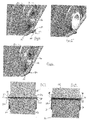
- FIG. 4 illustrates one side of the arm 16 in more detail and shows a pivot casting 24 and the two plate members 25, 26.
- Each pivot casting 24 has a circular boss 31.
- the interface comprises a "V" shaped slot 27 formed by a chamfer at the end of each of the plate members 25, 26.
- such a slot is suitable for deposition welding, for example by electric arc, MIG or TIG welding apparatus.
- the plates 25, 26 define a respective projection or tab 28, 29 which constitute a starting and a stopping surface for the deposition weld.
- Each projection projects about 25 mm prior to welding.
- Figure 7 illustrates the conventional arrangement from the underside prior to welding.
- the projections 28, 29 can be clearly seen at either end of the slot 27.
- the invention is illustrated in figures 5 and 8 .
- the projections 28, 29 are partially removed along with the corresponding weld bead. As seen in figure 8 , the remaining projection does not extend beyond the boss 31 provided on each pivot casting 24.
- the projections may be reduced in any convenient manner, for example by grinding, prior to anti corrosion treatment and painting.
- the method of fabrication comprises placing the two pivot castings 24 in a jig with the sides top and bottom of the excavator arm, and tack welding of the components prior to seam welding.
- the plate components of the arm are typically of steel having a thickness in the range 4-8 mm. After welding the projections and associated portions of weld are removed by grinding, so that for example 10-20 mm of projection is removed from either end of the weld, and 5-15 mm of the projection remains. In one embodiment a 25 mm projection is reduced to 10 mm.
Landscapes
- Engineering & Computer Science (AREA)
- Mechanical Engineering (AREA)
- Physics & Mathematics (AREA)
- Plasma & Fusion (AREA)
- Civil Engineering (AREA)
- Structural Engineering (AREA)
- General Engineering & Computer Science (AREA)
- Mining & Mineral Resources (AREA)
- Optics & Photonics (AREA)
- Materials Engineering (AREA)
- Chemical & Material Sciences (AREA)
- Butt Welding And Welding Of Specific Article (AREA)
- Body Structure For Vehicles (AREA)
- Shovels (AREA)
Abstract
Description
- This invention relates to a welded component, in particular a deposition welded, hollow steel fabrication for an articulating arm of an excavator, and a method of fabrication thereof.
- Steel fabrications are often employed in the manufacture of components for construction equipment and the like. In the case of an arm for lifting or loading, a fabrication may consist of a somewhat rectangular box section incorporating a pivot and comprising a plurality of substantially flat plates connected together by welding; such an arm can be both strong and of low mass and low inertia.
- Care is required during welding to avoid the introduction or creation of concentrations of stress, which may result in failure of the weld in use. In particular high stresses can be produced at the start or at the end of an electro-deposition weld, for example where two plates are joined together by a transverse weld.
- In such circumstances, it is conventional to provide a run-on and run-off feature at the end of the joint to be welded, generally in the form of a plate extension or protuberance. The weld is started and stopped on the projection which is at either end of the weld run, and this ensures that over the length of the substantive joint the weld is of substantially consistent quality.
- After completion of the weld, the run-on and run-off features, together with the start and end of the deposition weld, are removed by grinding to leave only the welded joint flush with the longitudinal edge of the respective plates. In this way any potential weld defect is removed from the start and stop positions, and a consistently strong fabrication is thus provided.
- Nevertheless it would be desirable to further reduce the stress levels at the start and end of such a deposition weld, in particular in the region of a pivot of a box section fabrication.
- According to the invention there is provided a method of fabricating a box section arm for an excavator, said arm defining a transverse pivot axis between the ends thereof, one side of said arm comprising substantially flat plate members meeting at a transverse plane coincident with said axis, and each plate member including opposite transverse projections at the mutually adjacent ends, the method comprising:
- transversely welding said plate members together, said weld commencing at the projections at one side, and finishing at the projections at the opposite side, and
- partially removing the projections and weld at both sides.
- Such a fabricated arm has reduced stress at each end of the transverse weld bead, and provides for an improved connection in the region of a pivot of the arm. It has been found that the number of fatigue cycles before failure is substantially increased by the invention, typically by 50-100%.
- The projections are preferably located at edges at the mutually adjacent ends of the plate members, for example at side edges of the box section arm. The projections preferably extend from a side edge of the plate members, most preferably at the mutually adjacent ends of the plate members. The projections may project in a direction parallel to the said transverse pivot axis and preferably project only in that direction. Each projection is preferably flush with the plate from which it projects.
- Continuous deposition welding is preferred, and the gap between the plates is preferably an open "V" in order to accommodate the deposition weld bead.
- The pivot axis may be defined by an annular casting to be welded along a peripheral edge to the sides of the arm, and to the flat plate members. Such a casting may define the pivot axis in a through bore, and one such casting is generally provided at each side of the box section, so that each casting is welded to both of the flat plate members, and the flat plate members are welded to each other.
- In another aspect the invention provides an arm for an excavator fabricated by the method of the invention, and an excavator fitted with such an arm. The fabricated arm of the invention may be used on other kinds of machinery having similarly pivoted arms.
- Other features of the invention will be apparent from the following description of a preferred embodiment illustrated by way of example only in the accompanying drawings, in which:-
-
Figure 1 illustrates in side elevation an exemplar excavator incorporating the invention, -
Figure 2 is a perspective view from one side and above, of an excavator arm incorporating the invention, -
Figure 3 corresponds tofigure 2 , and shows the excavator arm from one side and below, -
Figure 4 is an enlarged partial perspective of conventional weld projection prior to welding, -
Figure 5 is an enlarged partial perspective view of the invention after welding and finishing, -
Figure 6 corresponds tofigure 4 and shows conventional finishing of a welded joint, -
Figure 7 corresponds tofigure 4 and shows the excavator arm from below, prior to transverse welding, -
Figure 8 corresponds tofigure 6 and shows the excavator of the invention arm from below, after transverse welding and finishing. - With reference to
figure 1 , a conventional excavator 10 comprises a tracked chassis 11 on which is provided abody 12 comprising adriver cab 13 and an engine 14. A first arm 15 extends forwards from the body and supports thereon asecond pivoting arm 16. A hydraulic strut 17 controls pivoting of thearm 16, which carries at the free end ashovel 18. Many features of the excavator are omitted, in particular the first arm 15 may pivot up and down with respect to thebody 12, and theshovel 18 may pivot with respect to thesecond arm 16. The first and second arms are connected atpivot axis 19. - The second arm is illustrated in more detail in
figures 2 and 3 , and comprises a box-section comprising twoside plates 21, atop 22 and aunderside 23. A typical second arm has a length in the range of 1.9 to 3.0 m, but could be up to 6 m long. The width and height of the arm in the region of the pivot axis is around 300 mm, but could be less or more. As illustrated the arm tapers towards the ends thereof, but is typically of substantially constant width. - The
pivot axis 19 is defined by a pair ofpivot castings 24 which are welded in corresponding recesses of theside plates 21. Theunderside 23 is constituted by twoplate members axis 19. As can be seen fromfigure 3 , these plate members meet transversely underneath the castings 24 (as viewed), and must be welded together at this interface as well as to the side plates and pivot castings. The flat plate have an obtuse included angle, as illustrated. -
Figure 4 illustrates one side of thearm 16 in more detail and shows apivot casting 24 and the twoplate members pivot casting 24 has acircular boss 31. The interface comprises a "V"shaped slot 27 formed by a chamfer at the end of each of theplate members - At each end of the
transverse slot 27, theplates tab - Conventionally, after welding is completed, such projections are completely removed along with the corresponding weld bead to leave a flush finish, as illustrated in
figure 6 , in which the weld bead 30 is shown. -
Figure 7 illustrates the conventional arrangement from the underside prior to welding. Theprojections slot 27. - The invention is illustrated in
figures 5 and 8 . After welding theprojections figure 8 , the remaining projection does not extend beyond theboss 31 provided on eachpivot casting 24. The projections may be reduced in any convenient manner, for example by grinding, prior to anti corrosion treatment and painting. - The method of fabrication comprises placing the two
pivot castings 24 in a jig with the sides top and bottom of the excavator arm, and tack welding of the components prior to seam welding. The plate components of the arm are typically of steel having a thickness in the range 4-8 mm. After welding the projections and associated portions of weld are removed by grinding, so that for example 10-20 mm of projection is removed from either end of the weld, and 5-15 mm of the projection remains. In one embodiment a 25 mm projection is reduced to 10 mm.
Claims (15)
- A method of fabricating a box section arm for an excavator, said arm defining a transverse pivot axis between the ends thereof, one side of said arm comprising substantially flat plate members meeting at a transverse plane coincident with said axis, and each plate member including opposite transverse projections at the mutually adjacent ends, the method comprising:transversely welding said plate members together, said weld commencing at the projections at one side, and finishing at the projections at the opposite side, andpartially removing the projections and weld at both sides.
- The method of claim 1 wherein the step of transversely welding is by continuous deposition weld.
- The method of claim 1 or claim 2 including the preparatory step of chamfering the adjacent ends of the plate members to provide a "V" shaped slot for the transverse weld.
- The method of any of claims 1 to 3 wherein said pivot axis is defined by a annular bearing at either side of said arm, the bearings bridging said plate members, the method including the step of welding said bearings to said plate members.
- The method of claim 4 wherein said axis is positioned to one side of said arm immediately adjacent said plate members.
- The method of claim 4 or claim 5 wherein said annular bearings each comprise an externally facing circular boss coaxial about said axis, and said projections are removed so as to project less than each respective boss.
- The method according to any preceding claim wherein said projections are reduced in length by about 50-75%.
- The method of any of claims 1 to 6 wherein said projections are reduced in length by 10-20 mm.
- The method of any one of claims 1 to 6 wherein said projections project by 5-15 mm after said partial removal thereof.
- The method of any of claims 1 to 9 wherein the step of partial removal is by grinding.
- A box-selection arm for an excavator, said arm being made by the method of any of claims 1 to 10.
- A box section arm for an excavator, said arm defining a transverse pivot axis between the ends thereof, one side of said arm comprising two substantially flat plate members meeting at the transverse plane coincident with said axis, and each plate member including opposite transverse projections at the mutually adjacent ends, between which a continuous weld bead projects, said projections protruding 10-20 mm and having a flush end face.
- An excavator having a box-section arm according to claim 11 or claim 12.
- A method of fabricating a box-section arm for a excavator, substantially as described herein with reference to figures 5 and 8 of the accompanying drawings.
- A box-section arm substantially as described herein with reference to figures 5 and 8 of the accompanying drawings.
Applications Claiming Priority (1)
| Application Number | Priority Date | Filing Date | Title |
|---|---|---|---|
| GB1316070.0A GB2518000B (en) | 2013-09-10 | 2013-09-10 | Welded component and method of fabrication |
Publications (2)
| Publication Number | Publication Date |
|---|---|
| EP2845953A1 true EP2845953A1 (en) | 2015-03-11 |
| EP2845953B1 EP2845953B1 (en) | 2017-03-01 |
Family
ID=49486978
Family Applications (1)
| Application Number | Title | Priority Date | Filing Date |
|---|---|---|---|
| EP14184019.9A Active EP2845953B1 (en) | 2013-09-10 | 2014-09-09 | Welded excavator box section arm and method of fabrication |
Country Status (8)
| Country | Link |
|---|---|
| US (1) | US9856624B2 (en) |
| EP (1) | EP2845953B1 (en) |
| JP (1) | JP6512779B2 (en) |
| KR (1) | KR20150029598A (en) |
| CN (1) | CN104416261B (en) |
| BR (1) | BR102014022303B1 (en) |
| GB (1) | GB2518000B (en) |
| IN (1) | IN2014DE02581A (en) |
Cited By (2)
| Publication number | Priority date | Publication date | Assignee | Title |
|---|---|---|---|---|
| US10688600B2 (en) | 2016-12-13 | 2020-06-23 | Caterpillar Inc. | Structure having stress protected groove weld and structural members forming the same |
| US10981253B2 (en) | 2016-12-13 | 2021-04-20 | Caterpillar Inc. | Structure having stress protected groove weld and structural members forming the same |
Families Citing this family (5)
| Publication number | Priority date | Publication date | Assignee | Title |
|---|---|---|---|---|
| CN107859079A (en) * | 2016-09-22 | 2018-03-30 | 日立建机株式会社 | Preceding apparatus for work and excavator |
| EP3612683B1 (en) | 2017-04-19 | 2023-03-08 | Clark Equipment Company | Loader lift arm assembly for a power machine |
| CN107956227A (en) * | 2017-12-12 | 2018-04-24 | 肖水顺 | Middle pin hole sticking board type mental rocking arm |
| DE102019110607A1 (en) * | 2019-04-24 | 2020-10-29 | Liebherr-France Sas | Equipment component |
| CN113073694B (en) * | 2021-04-14 | 2022-05-17 | 山推工程机械股份有限公司 | Pivot box, bogie frame and bulldozer |
Citations (4)
| Publication number | Priority date | Publication date | Assignee | Title |
|---|---|---|---|---|
| US4392314A (en) * | 1982-02-16 | 1983-07-12 | J. I. Case Company | Boom and dipper stick construction |
| JP2001123471A (en) * | 1999-10-22 | 2001-05-08 | Shin Caterpillar Mitsubishi Ltd | Work arm structure of work machine |
| JP2004092210A (en) * | 2002-08-30 | 2004-03-25 | Komatsu Ltd | Work machine |
| JP2013147794A (en) * | 2012-01-17 | 2013-08-01 | Hitachi Constr Mach Co Ltd | Arm for construction machine |
Family Cites Families (4)
| Publication number | Priority date | Publication date | Assignee | Title |
|---|---|---|---|---|
| WO2005001211A1 (en) * | 2003-06-30 | 2005-01-06 | Hitachi Construction Machinery Co., Ltd. | Working arm for construction machine and method of producing the same |
| CN103547738B (en) * | 2011-05-19 | 2016-01-20 | 日立建机株式会社 | Arm for construction machinery |
| US9255378B2 (en) | 2011-05-19 | 2016-02-09 | Hitachi Construction Machinery Co., Ltd. | Arm for construction machine |
| CN202390866U (en) * | 2011-12-20 | 2012-08-22 | 中联重科股份有限公司 | Excavator bucket rod and excavator |
-
2013
- 2013-09-10 GB GB1316070.0A patent/GB2518000B/en active Active
-
2014
- 2014-09-09 JP JP2014183412A patent/JP6512779B2/en active Active
- 2014-09-09 EP EP14184019.9A patent/EP2845953B1/en active Active
- 2014-09-09 US US14/481,724 patent/US9856624B2/en active Active
- 2014-09-09 BR BR102014022303-7A patent/BR102014022303B1/en active IP Right Grant
- 2014-09-10 IN IN2581DE2014 patent/IN2014DE02581A/en unknown
- 2014-09-10 CN CN201410459231.9A patent/CN104416261B/en active Active
- 2014-09-11 KR KR20140120252A patent/KR20150029598A/en not_active Abandoned
Patent Citations (4)
| Publication number | Priority date | Publication date | Assignee | Title |
|---|---|---|---|---|
| US4392314A (en) * | 1982-02-16 | 1983-07-12 | J. I. Case Company | Boom and dipper stick construction |
| JP2001123471A (en) * | 1999-10-22 | 2001-05-08 | Shin Caterpillar Mitsubishi Ltd | Work arm structure of work machine |
| JP2004092210A (en) * | 2002-08-30 | 2004-03-25 | Komatsu Ltd | Work machine |
| JP2013147794A (en) * | 2012-01-17 | 2013-08-01 | Hitachi Constr Mach Co Ltd | Arm for construction machine |
Cited By (3)
| Publication number | Priority date | Publication date | Assignee | Title |
|---|---|---|---|---|
| US10688600B2 (en) | 2016-12-13 | 2020-06-23 | Caterpillar Inc. | Structure having stress protected groove weld and structural members forming the same |
| US10981253B2 (en) | 2016-12-13 | 2021-04-20 | Caterpillar Inc. | Structure having stress protected groove weld and structural members forming the same |
| US11253956B2 (en) | 2016-12-13 | 2022-02-22 | Caterpillar Inc. | Structure having stress protected groove weld and structural members forming the same |
Also Published As
| Publication number | Publication date |
|---|---|
| GB2518000B (en) | 2017-05-31 |
| JP6512779B2 (en) | 2019-05-15 |
| BR102014022303A2 (en) | 2016-05-31 |
| EP2845953B1 (en) | 2017-03-01 |
| CN104416261B (en) | 2018-11-27 |
| KR20150029598A (en) | 2015-03-18 |
| GB201316070D0 (en) | 2013-10-23 |
| JP2015054350A (en) | 2015-03-23 |
| US9856624B2 (en) | 2018-01-02 |
| IN2014DE02581A (en) | 2015-06-26 |
| CN104416261A (en) | 2015-03-18 |
| GB2518000A (en) | 2015-03-11 |
| BR102014022303B1 (en) | 2020-10-20 |
| US20150071752A1 (en) | 2015-03-12 |
| BR102014022303A8 (en) | 2018-06-05 |
Similar Documents
| Publication | Publication Date | Title |
|---|---|---|
| EP2845953B1 (en) | Welded excavator box section arm and method of fabrication | |
| CN105935843B (en) | A method of welding structural parts | |
| US20180029851A1 (en) | Linkage assembly for machine | |
| JP5994879B2 (en) | Lap fillet arc welded joint | |
| JP2017080802A (en) | Lap-fillet arc welded joint, joining structure for press-formed component | |
| KR101485101B1 (en) | method of constructing truss structure | |
| US20100001044A1 (en) | Full penetration weld joint | |
| JP5866947B2 (en) | Overlap fillet arc welded joint with excellent fatigue characteristics and method for manufacturing the same | |
| JP2006306211A (en) | Tailored blank welded structural members | |
| JPS62286680A (en) | Butt welding method for aluminum thin plate | |
| JP2018158364A (en) | Fillet-welded joint structure of vehicle body closed cross-sectional member | |
| CN115319350A (en) | Frame assembly welding tool and frame assembly welding method | |
| JPH09253843A (en) | Stress relaxation weld bead structure | |
| US10072392B2 (en) | Boom foot design with protruding flanges | |
| CN118545206A (en) | A rapid assembly device for the joint beam of the deck of an offshore platform | |
| US9545693B2 (en) | Consumable insert for welding | |
| JP3567366B2 (en) | Work arm structure of work machine | |
| US8304093B2 (en) | Apparatus and method for preferential formation of weld joint | |
| CN108463595B (en) | Improved upper hinge design for buckets | |
| JP2012115858A (en) | Groove of weld joint and welding procedure | |
| JP4698199B2 (en) | Closed section welded structure and manufacturing method thereof | |
| JP3292412B2 (en) | How to attach chucking plate | |
| JP3462424B2 (en) | Truck frame for construction machinery | |
| JP2017160740A (en) | Upper frame of construction machine | |
| JPH0788650A (en) | Method for preventing longitudinal cracking of end in one-side submerged arc welding |
Legal Events
| Date | Code | Title | Description |
|---|---|---|---|
| 17P | Request for examination filed |
Effective date: 20140909 |
|
| AK | Designated contracting states |
Kind code of ref document: A1 Designated state(s): AL AT BE BG CH CY CZ DE DK EE ES FI FR GB GR HR HU IE IS IT LI LT LU LV MC MK MT NL NO PL PT RO RS SE SI SK SM TR |
|
| AX | Request for extension of the european patent |
Extension state: BA ME |
|
| PUAI | Public reference made under article 153(3) epc to a published international application that has entered the european phase |
Free format text: ORIGINAL CODE: 0009012 |
|
| R17P | Request for examination filed (corrected) |
Effective date: 20150505 |
|
| RBV | Designated contracting states (corrected) |
Designated state(s): AL AT BE BG CH CY CZ DE DK EE ES FI FR GB GR HR HU IE IS IT LI LT LU LV MC MK MT NL NO PL PT RO RS SE SI SK SM TR |
|
| 17Q | First examination report despatched |
Effective date: 20160421 |
|
| GRAP | Despatch of communication of intention to grant a patent |
Free format text: ORIGINAL CODE: EPIDOSNIGR1 |
|
| RIC1 | Information provided on ipc code assigned before grant |
Ipc: B23K 9/23 20060101ALI20160822BHEP Ipc: B23K 31/02 20060101ALI20160822BHEP Ipc: E02F 3/38 20060101AFI20160822BHEP Ipc: B23K 9/167 20060101ALI20160822BHEP Ipc: B23K 9/00 20060101ALI20160822BHEP Ipc: B23K 37/08 20060101ALI20160822BHEP Ipc: B23K 9/173 20060101ALI20160822BHEP Ipc: B23K 103/04 20060101ALI20160822BHEP Ipc: B23K 33/00 20060101ALI20160822BHEP Ipc: B23K 9/025 20060101ALI20160822BHEP |
|
| INTG | Intention to grant announced |
Effective date: 20160922 |
|
| STAA | Information on the status of an ep patent application or granted ep patent |
Free format text: STATUS: GRANT OF PATENT IS INTENDED |
|
| GRAS | Grant fee paid |
Free format text: ORIGINAL CODE: EPIDOSNIGR3 |
|
| GRAA | (expected) grant |
Free format text: ORIGINAL CODE: 0009210 |
|
| STAA | Information on the status of an ep patent application or granted ep patent |
Free format text: STATUS: THE PATENT HAS BEEN GRANTED |
|
| AK | Designated contracting states |
Kind code of ref document: B1 Designated state(s): AL AT BE BG CH CY CZ DE DK EE ES FI FR GB GR HR HU IE IS IT LI LT LU LV MC MK MT NL NO PL PT RO RS SE SI SK SM TR |
|
| REG | Reference to a national code |
Ref country code: GB Ref legal event code: FG4D |
|
| REG | Reference to a national code |
Ref country code: CH Ref legal event code: EP Ref country code: AT Ref legal event code: REF Ref document number: 871510 Country of ref document: AT Kind code of ref document: T Effective date: 20170315 |
|
| REG | Reference to a national code |
Ref country code: IE Ref legal event code: FG4D |
|
| REG | Reference to a national code |
Ref country code: DE Ref legal event code: R096 Ref document number: 602014007062 Country of ref document: DE |
|
| REG | Reference to a national code |
Ref country code: NL Ref legal event code: MP Effective date: 20170301 |
|
| REG | Reference to a national code |
Ref country code: LT Ref legal event code: MG4D |
|
| REG | Reference to a national code |
Ref country code: AT Ref legal event code: MK05 Ref document number: 871510 Country of ref document: AT Kind code of ref document: T Effective date: 20170301 |
|
| PG25 | Lapsed in a contracting state [announced via postgrant information from national office to epo] |
Ref country code: FI Free format text: LAPSE BECAUSE OF FAILURE TO SUBMIT A TRANSLATION OF THE DESCRIPTION OR TO PAY THE FEE WITHIN THE PRESCRIBED TIME-LIMIT Effective date: 20170301 Ref country code: LT Free format text: LAPSE BECAUSE OF FAILURE TO SUBMIT A TRANSLATION OF THE DESCRIPTION OR TO PAY THE FEE WITHIN THE PRESCRIBED TIME-LIMIT Effective date: 20170301 Ref country code: NO Free format text: LAPSE BECAUSE OF FAILURE TO SUBMIT A TRANSLATION OF THE DESCRIPTION OR TO PAY THE FEE WITHIN THE PRESCRIBED TIME-LIMIT Effective date: 20170601 Ref country code: HR Free format text: LAPSE BECAUSE OF FAILURE TO SUBMIT A TRANSLATION OF THE DESCRIPTION OR TO PAY THE FEE WITHIN THE PRESCRIBED TIME-LIMIT Effective date: 20170301 Ref country code: GR Free format text: LAPSE BECAUSE OF FAILURE TO SUBMIT A TRANSLATION OF THE DESCRIPTION OR TO PAY THE FEE WITHIN THE PRESCRIBED TIME-LIMIT Effective date: 20170602 |
|
| PG25 | Lapsed in a contracting state [announced via postgrant information from national office to epo] |
Ref country code: BG Free format text: LAPSE BECAUSE OF FAILURE TO SUBMIT A TRANSLATION OF THE DESCRIPTION OR TO PAY THE FEE WITHIN THE PRESCRIBED TIME-LIMIT Effective date: 20170601 Ref country code: LV Free format text: LAPSE BECAUSE OF FAILURE TO SUBMIT A TRANSLATION OF THE DESCRIPTION OR TO PAY THE FEE WITHIN THE PRESCRIBED TIME-LIMIT Effective date: 20170301 Ref country code: AT Free format text: LAPSE BECAUSE OF FAILURE TO SUBMIT A TRANSLATION OF THE DESCRIPTION OR TO PAY THE FEE WITHIN THE PRESCRIBED TIME-LIMIT Effective date: 20170301 Ref country code: ES Free format text: LAPSE BECAUSE OF FAILURE TO SUBMIT A TRANSLATION OF THE DESCRIPTION OR TO PAY THE FEE WITHIN THE PRESCRIBED TIME-LIMIT Effective date: 20170301 Ref country code: RS Free format text: LAPSE BECAUSE OF FAILURE TO SUBMIT A TRANSLATION OF THE DESCRIPTION OR TO PAY THE FEE WITHIN THE PRESCRIBED TIME-LIMIT Effective date: 20170301 Ref country code: SE Free format text: LAPSE BECAUSE OF FAILURE TO SUBMIT A TRANSLATION OF THE DESCRIPTION OR TO PAY THE FEE WITHIN THE PRESCRIBED TIME-LIMIT Effective date: 20170301 |
|
| REG | Reference to a national code |
Ref country code: FR Ref legal event code: PLFP Year of fee payment: 4 |
|
| PG25 | Lapsed in a contracting state [announced via postgrant information from national office to epo] |
Ref country code: NL Free format text: LAPSE BECAUSE OF FAILURE TO SUBMIT A TRANSLATION OF THE DESCRIPTION OR TO PAY THE FEE WITHIN THE PRESCRIBED TIME-LIMIT Effective date: 20170301 |
|
| PG25 | Lapsed in a contracting state [announced via postgrant information from national office to epo] |
Ref country code: RO Free format text: LAPSE BECAUSE OF FAILURE TO SUBMIT A TRANSLATION OF THE DESCRIPTION OR TO PAY THE FEE WITHIN THE PRESCRIBED TIME-LIMIT Effective date: 20170301 Ref country code: EE Free format text: LAPSE BECAUSE OF FAILURE TO SUBMIT A TRANSLATION OF THE DESCRIPTION OR TO PAY THE FEE WITHIN THE PRESCRIBED TIME-LIMIT Effective date: 20170301 Ref country code: SK Free format text: LAPSE BECAUSE OF FAILURE TO SUBMIT A TRANSLATION OF THE DESCRIPTION OR TO PAY THE FEE WITHIN THE PRESCRIBED TIME-LIMIT Effective date: 20170301 Ref country code: CZ Free format text: LAPSE BECAUSE OF FAILURE TO SUBMIT A TRANSLATION OF THE DESCRIPTION OR TO PAY THE FEE WITHIN THE PRESCRIBED TIME-LIMIT Effective date: 20170301 |
|
| PG25 | Lapsed in a contracting state [announced via postgrant information from national office to epo] |
Ref country code: PT Free format text: LAPSE BECAUSE OF FAILURE TO SUBMIT A TRANSLATION OF THE DESCRIPTION OR TO PAY THE FEE WITHIN THE PRESCRIBED TIME-LIMIT Effective date: 20170703 Ref country code: SM Free format text: LAPSE BECAUSE OF FAILURE TO SUBMIT A TRANSLATION OF THE DESCRIPTION OR TO PAY THE FEE WITHIN THE PRESCRIBED TIME-LIMIT Effective date: 20170301 Ref country code: PL Free format text: LAPSE BECAUSE OF FAILURE TO SUBMIT A TRANSLATION OF THE DESCRIPTION OR TO PAY THE FEE WITHIN THE PRESCRIBED TIME-LIMIT Effective date: 20170301 Ref country code: IS Free format text: LAPSE BECAUSE OF FAILURE TO SUBMIT A TRANSLATION OF THE DESCRIPTION OR TO PAY THE FEE WITHIN THE PRESCRIBED TIME-LIMIT Effective date: 20170701 |
|
| REG | Reference to a national code |
Ref country code: DE Ref legal event code: R097 Ref document number: 602014007062 Country of ref document: DE |
|
| PLBE | No opposition filed within time limit |
Free format text: ORIGINAL CODE: 0009261 |
|
| STAA | Information on the status of an ep patent application or granted ep patent |
Free format text: STATUS: NO OPPOSITION FILED WITHIN TIME LIMIT |
|
| PG25 | Lapsed in a contracting state [announced via postgrant information from national office to epo] |
Ref country code: DK Free format text: LAPSE BECAUSE OF FAILURE TO SUBMIT A TRANSLATION OF THE DESCRIPTION OR TO PAY THE FEE WITHIN THE PRESCRIBED TIME-LIMIT Effective date: 20170301 |
|
| 26N | No opposition filed |
Effective date: 20171204 |
|
| PG25 | Lapsed in a contracting state [announced via postgrant information from national office to epo] |
Ref country code: SI Free format text: LAPSE BECAUSE OF FAILURE TO SUBMIT A TRANSLATION OF THE DESCRIPTION OR TO PAY THE FEE WITHIN THE PRESCRIBED TIME-LIMIT Effective date: 20170301 |
|
| REG | Reference to a national code |
Ref country code: CH Ref legal event code: PL |
|
| PG25 | Lapsed in a contracting state [announced via postgrant information from national office to epo] |
Ref country code: MC Free format text: LAPSE BECAUSE OF FAILURE TO SUBMIT A TRANSLATION OF THE DESCRIPTION OR TO PAY THE FEE WITHIN THE PRESCRIBED TIME-LIMIT Effective date: 20170301 |
|
| REG | Reference to a national code |
Ref country code: IE Ref legal event code: MM4A |
|
| REG | Reference to a national code |
Ref country code: BE Ref legal event code: MM Effective date: 20170930 |
|
| PG25 | Lapsed in a contracting state [announced via postgrant information from national office to epo] |
Ref country code: LU Free format text: LAPSE BECAUSE OF NON-PAYMENT OF DUE FEES Effective date: 20170909 |
|
| PG25 | Lapsed in a contracting state [announced via postgrant information from national office to epo] |
Ref country code: LI Free format text: LAPSE BECAUSE OF NON-PAYMENT OF DUE FEES Effective date: 20170930 Ref country code: CH Free format text: LAPSE BECAUSE OF NON-PAYMENT OF DUE FEES Effective date: 20170930 Ref country code: IE Free format text: LAPSE BECAUSE OF NON-PAYMENT OF DUE FEES Effective date: 20170909 |
|
| PG25 | Lapsed in a contracting state [announced via postgrant information from national office to epo] |
Ref country code: BE Free format text: LAPSE BECAUSE OF NON-PAYMENT OF DUE FEES Effective date: 20170930 |
|
| REG | Reference to a national code |
Ref country code: FR Ref legal event code: PLFP Year of fee payment: 5 |
|
| PG25 | Lapsed in a contracting state [announced via postgrant information from national office to epo] |
Ref country code: MT Free format text: LAPSE BECAUSE OF NON-PAYMENT OF DUE FEES Effective date: 20170909 |
|
| PG25 | Lapsed in a contracting state [announced via postgrant information from national office to epo] |
Ref country code: HU Free format text: LAPSE BECAUSE OF FAILURE TO SUBMIT A TRANSLATION OF THE DESCRIPTION OR TO PAY THE FEE WITHIN THE PRESCRIBED TIME-LIMIT; INVALID AB INITIO Effective date: 20140909 |
|
| PG25 | Lapsed in a contracting state [announced via postgrant information from national office to epo] |
Ref country code: CY Free format text: LAPSE BECAUSE OF FAILURE TO SUBMIT A TRANSLATION OF THE DESCRIPTION OR TO PAY THE FEE WITHIN THE PRESCRIBED TIME-LIMIT Effective date: 20170301 |
|
| PG25 | Lapsed in a contracting state [announced via postgrant information from national office to epo] |
Ref country code: MK Free format text: LAPSE BECAUSE OF FAILURE TO SUBMIT A TRANSLATION OF THE DESCRIPTION OR TO PAY THE FEE WITHIN THE PRESCRIBED TIME-LIMIT Effective date: 20170301 |
|
| PG25 | Lapsed in a contracting state [announced via postgrant information from national office to epo] |
Ref country code: TR Free format text: LAPSE BECAUSE OF FAILURE TO SUBMIT A TRANSLATION OF THE DESCRIPTION OR TO PAY THE FEE WITHIN THE PRESCRIBED TIME-LIMIT Effective date: 20170301 |
|
| PG25 | Lapsed in a contracting state [announced via postgrant information from national office to epo] |
Ref country code: AL Free format text: LAPSE BECAUSE OF FAILURE TO SUBMIT A TRANSLATION OF THE DESCRIPTION OR TO PAY THE FEE WITHIN THE PRESCRIBED TIME-LIMIT Effective date: 20170301 |
|
| PLAA | Information modified related to event that no opposition was filed |
Free format text: ORIGINAL CODE: 0009299DELT |
|
| PLBE | No opposition filed within time limit |
Free format text: ORIGINAL CODE: 0009261 |
|
| R26N | No opposition filed (corrected) |
Effective date: 20171204 |
|
| 26N | No opposition filed |
Effective date: 20171204 |
|
| P01 | Opt-out of the competence of the unified patent court (upc) registered |
Effective date: 20230524 |
|
| PGFP | Annual fee paid to national office [announced via postgrant information from national office to epo] |
Ref country code: DE Payment date: 20250919 Year of fee payment: 12 |
|
| PGFP | Annual fee paid to national office [announced via postgrant information from national office to epo] |
Ref country code: IT Payment date: 20250919 Year of fee payment: 12 |
|
| PGFP | Annual fee paid to national office [announced via postgrant information from national office to epo] |
Ref country code: GB Payment date: 20250917 Year of fee payment: 12 |
|
| PGFP | Annual fee paid to national office [announced via postgrant information from national office to epo] |
Ref country code: FR Payment date: 20250922 Year of fee payment: 12 |