EP2845672A1 - Drill bit - Google Patents
Drill bit Download PDFInfo
- Publication number
- EP2845672A1 EP2845672A1 EP14183745.0A EP14183745A EP2845672A1 EP 2845672 A1 EP2845672 A1 EP 2845672A1 EP 14183745 A EP14183745 A EP 14183745A EP 2845672 A1 EP2845672 A1 EP 2845672A1
- Authority
- EP
- European Patent Office
- Prior art keywords
- drill
- core reinforcement
- width
- webs
- helix
- Prior art date
- Legal status (The legal status is an assumption and is not a legal conclusion. Google has not performed a legal analysis and makes no representation as to the accuracy of the status listed.)
- Granted
Links
- 230000002787 reinforcement Effects 0.000 claims abstract description 61
- 239000000428 dust Substances 0.000 claims description 4
- 230000007423 decrease Effects 0.000 claims 1
- 238000005553 drilling Methods 0.000 description 5
- 230000008901 benefit Effects 0.000 description 4
- 230000007704 transition Effects 0.000 description 4
- 230000000694 effects Effects 0.000 description 2
- 230000002349 favourable effect Effects 0.000 description 2
- 239000011435 rock Substances 0.000 description 2
- 230000003313 weakening effect Effects 0.000 description 2
- 238000010521 absorption reaction Methods 0.000 description 1
- 230000004323 axial length Effects 0.000 description 1
- 238000004200 deflagration Methods 0.000 description 1
- 238000011161 development Methods 0.000 description 1
- 230000018109 developmental process Effects 0.000 description 1
- 230000007774 longterm Effects 0.000 description 1
- 235000012054 meals Nutrition 0.000 description 1
- 230000003014 reinforcing effect Effects 0.000 description 1
- 230000003763 resistance to breakage Effects 0.000 description 1
- 230000035939 shock Effects 0.000 description 1
- 239000002699 waste material Substances 0.000 description 1
Images


Classifications
-
- B—PERFORMING OPERATIONS; TRANSPORTING
- B23—MACHINE TOOLS; METAL-WORKING NOT OTHERWISE PROVIDED FOR
- B23B—TURNING; BORING
- B23B51/00—Tools for drilling machines
- B23B51/02—Twist drills
-
- B—PERFORMING OPERATIONS; TRANSPORTING
- B28—WORKING CEMENT, CLAY, OR STONE
- B28D—WORKING STONE OR STONE-LIKE MATERIALS
- B28D1/00—Working stone or stone-like materials, e.g. brick, concrete or glass, not provided for elsewhere; Machines, devices, tools therefor
- B28D1/14—Working stone or stone-like materials, e.g. brick, concrete or glass, not provided for elsewhere; Machines, devices, tools therefor by boring or drilling
- B28D1/146—Tools therefor
-
- B—PERFORMING OPERATIONS; TRANSPORTING
- B23—MACHINE TOOLS; METAL-WORKING NOT OTHERWISE PROVIDED FOR
- B23B—TURNING; BORING
- B23B2226/00—Materials of tools or workpieces not comprising a metal
- B23B2226/75—Stone, rock or concrete
-
- B—PERFORMING OPERATIONS; TRANSPORTING
- B23—MACHINE TOOLS; METAL-WORKING NOT OTHERWISE PROVIDED FOR
- B23B—TURNING; BORING
- B23B2251/00—Details of tools for drilling machines
- B23B2251/40—Flutes, i.e. chip conveying grooves
- B23B2251/406—Flutes, i.e. chip conveying grooves of special form not otherwise provided for
-
- B—PERFORMING OPERATIONS; TRANSPORTING
- B23—MACHINE TOOLS; METAL-WORKING NOT OTHERWISE PROVIDED FOR
- B23B—TURNING; BORING
- B23B2251/00—Details of tools for drilling machines
- B23B2251/44—Margins, i.e. the narrow portion of the land which is not cut away to provide clearance on the circumferential surface
- B23B2251/446—Drills with variable margins
Definitions
- the invention relates to a drill, according to the preamble of claim 1, in particular a rock drill with a equipped with a carbide insert drill head.
- Such a drill is for example from the DE 197 27 070 C2 known. This drill with core reinforcement has proven in practice to be particularly powerful and durable.
- Core reinforcement is understood as meaning a convexity in the direction of the longitudinal axis of the drill, that is to say a crowned structure of the drill core within each drill waste discharge groove, viewed in a longitudinal section of the drill.
- the invention has for its object to provide a drill according to the preamble of claim 1, whose long-term stability and resistance to breakage is further increased.
- a drill is provided with a core reinforcement whose back land width is lower at the drill head end than at the shank end of the lands or the drill spiral.
- the drill bit is provided in a conventional manner with a drill head with a carbide insert.
- the drill according to the invention is thus particularly suitable for rock and the like.
- the core reinforcement on the shank-side end of the helix leaner that is, less spherical.
- the rigidity and stability of the core is not affected by this or only to a very limited extent, because the absolute depth of the Bohrmehlabschreibnut at the top of the core reinforcement remains unchanged.
- the slimmer design provides more space for the removal of the dustbin by further increasing the volume of the dustbin discharge groove to the side of the center of the core reinforcement. This compensates by far the reduction of the volume or clearance available for the removal of the drilling dust per axial length section of the drill in the region of the shank-side end of the helix.
- the width of the back ribs is correspondingly lower than at the shank end.
- the drill is less rigid there.
- the more spherical configuration of the core reinforcement that is to say a design with larger radii of the convexity in the longitudinal section of the drill, there is a more massive spiral section available, which accordingly transmits the introduced impact energy better.
- the core reinforcement is made stiffer at the point where the drill is weakened by a weaker helix, and less rigid at the point where the drill is stiffer due to a stiffer helix having a wider back.
- Another advantage results from the reduction of the back width in the front area of the drill. Due to the narrower back webs, there is less contact surface between the drill hole and the drill. It results in less friction, which increases the drilling speed leads, especially during the creation of a borehole. The front part of the drill is already in contact with the drill hole at the beginning of the drilling, and its friction is decisive for the drilling performance.
- the shock wave introduced from the shaft end onto the drill can be better introduced into the drill spiral, whereby more impact energy is introduced into the drill head, which increases the drill performance.
- the change in shape of the core reinforcement is symmetrical, ie on both flanks of the core reinforcement mirror image of each other.
- the maximum possible increase in volume is achieved, which simultaneously prevents weakening of the core reinforcement.
- the core thickness of the drill measured at the tip or center of the core reinforcement, constant over the course of the helix. This avoids weakening the drill and reducing rigidity due to any reduction in core diameter.
- variable core reinforcement is combined with a drill spiral variable in the form of the variable spine width of the web.
- the shape of the core reinforcement changes over the course of the drill.
- the surface of the core reinforcement is reduced in a favorable embodiment of the shank end of the helix.
- the web over the course of the drill spiral considered a different mass. This surprisingly leads to avoid resonances due to the introduced longitudinal pulses of impact energy.
- this embodiment has the particular advantage that at the point at which the web wear is largest, the largest web mass is available. This point, ie the drill head end of the conveyor spiral, is most frequently in contact with the borehole surrounding the drill bit and is therefore exposed to the strongest wear. In this respect, in this embodiment, a particularly favorable wear compensation.
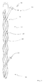
- the in Fig. 1 illustrated drill 10 has a drill bit 12 which extends from a shaft end 14, which is also referred to as the rear end, to a front end or drill bit end 16.
- the drill 10 has in the field of helix in a conventional manner a Bohrmehlabbownut 18, which is formed spirally encircling.
- a back web 20 is likewise designed to run in the same direction in a spiral manner, which back web 20 is embodied according to the invention in a special manner, as described below.
- the Bohrmehlabbow 18 has a core reinforcement 22.
- the core reinforcement 22 is more spherical in the area of the drill head end 16 and sharper or slimmer in the region of the shaft end 14 in the sense of a smaller cross section of the core reinforcement. Regarding the shape of the core reinforcement 22 in detail let the Figures 2 and 3 directed.
- the width 24 of the web 20 in the region of the drill head 16 is relatively narrow and the width 26 of the web 20 in the region of the shaft end 24 is large.
- the width 24 at the drill head end 16 is 2mm and the width 26 at the shaft end 14 is 5mm.
- the ratio of the back widths 24 to 26 can be adapted to the requirements in a wide range.
- the width ratio can also be 1 to 1.2 or up to 1 to 6.
- the dorsal ridge width ratio is between 1 to 1.5 and 1 to 3.5, more preferably between 1 in 2 and 1 in 3.
- the core reinforcement 22 changes in its configuration in the opposite direction to the change in the width 24 or 26.
- the core reinforcement 22 is wider in the area of the drill head end 16, so narrow at the point where the width 24 of the web 20 is narrower, and in the region of the shank end 14, at which point the width 26 of the web 20 is wider. This results in the desired compensation of the relatively narrower meal removal groove 18 in the region of the shank end 14 due to the higher width 24 and thus provides a relative increase in the Bohrmehlabssel 18, despite increasing the stiffness.
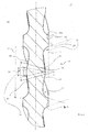
- Fig. 2 It can be seen that almost two courses of the helix are shown.
- the shaft end side web width 26a is larger than the drill head facing web width 26b.
- the Bohrmehlabbownut 18 has symmetrical outlet angles 30 and 32. This means the end angle of the Bohrmehlabbownut 18 to the web 20 toward meant, ie at the transition between the Bohrmehlabschreibnut 18 and the web 20th
- the outlet angle 30 at the drill-head-side end of the web 20 is exactly the same as the outlet angle 32 at the shank-side end of the web 20.
- this angle is 72 °, but can be adapted in many areas to the requirements. In order to limit the wear and to avoid jamming of the drill, the angle should, if possible, be significantly less than 85 °, preferably less than 80 °.
- the Bohrmehlabbow 18 is configured with the core reinforcement 22 in a special way.
- the core reinforcement 22 is quite slender.
- Their central radius 40 ie the radius of the convexity in the view according to Fig.2 in the immediate vicinity of the central center of the core reinforcement 22, is quite low. In the illustrated embodiment, it is significantly less than the nominal diameter of the drill, namely about half of the nominal diameter. This radius is detected via the central central 20 ° of the convex core reinforcement 22.
- the side radius 42 is significantly larger in contrast. In the illustrated embodiment, it is slightly less than the nominal diameter of the drill, which is slightly larger than the diameter of the drill in the region of the webs 20 due to the projecting in a conventional manner carbide tip. But it can also be slightly larger than the nominal diameter and can be preferably determined as an angle of about 35 ° over the central convexity of the core reinforcement 22.
- flanks of the core reinforcement 22 namely the leading edge 46 facing the drill head and the return flank 48, are straight and flat.
- the skew angle against the drill axis is between 5 and 18 degrees and in the illustrated embodiment about 10 degrees.
- the core reinforcement 22 becomes sharper and narrower.
- the Bohrmehlabschreibnut 18 in the region of the flutes 52 and 54 has an involute adhering structure, almost to the point where it merges into the center 60 of the core reinforcement 22.
- FIG. 3 shows the configuration of the Bohrmehlabschreibnut 18 and the core reinforcement 22 in the region of the drill head end of the coil.
- the core reinforcement 22 is in the view according to FIG Fig. 3 , so viewed in the longitudinal section through the drill, much more spherical. This results in that the central radius 40 and the side radius 42 coincide and are substantially larger than the respective radii according to FIG Fig. 2 , In the illustrated embodiment, both radii are about as large as twice the nominal diameter of the drill 10th
- the flutes 52 and 54 are such that, viewed from the outlet angles 30 and 32, they pass quite quickly into the convexity of the core reinforcement 22. Immediately following the concave region of the flutes 52 and 54, the convex region of the core reinforcement 22 adjoins in this embodiment.
- the convexity range of the core reinforcement 22 in this embodiment assumes a convexity width 70 that is opposite to the convexity width 70 in FIG Fig. 2 is significantly increased. It is significantly more than half the width 72 of the Bohrmehlabschreibnut 18.
- the width ratio is at the head end according to Fig. 3 about 0.8 to 1 while it is about 0.2 to 1 at the shank end.
- the ratio of the convexity width 70 to the drill dust removal groove width 72 is adaptable to the requirements in wide proportions, and a more convexity of the core reinforcement 22 is inherent with a relatively higher convexity width.
- width ratio of the widths 24 and 26 of the webs 20 here is 1 to 2
- the core reinforcement 22 changes in the opposite sense to the width change of the webs 20 as described above.
- the rear third 80 is equipped with a larger web width 26, and the two front thirds 82 of the drill 10 have a smaller web width 24. In between, there is a continuous transition.
Abstract
Die Erfindung weist einen Bohrer, mit einer Bohrerwendel (12), bei welcher sich zueinander symmetrische Stege (20) schraubenwendelförmig um einen Kern erstrecken, wobei zwischen den Stegen Nuten (18) verbleiben, deren Breite (72) die Rückenbreite (24) der Stege (20) übersteigt und wobei die Nuten (18) an ihren Nutengrund eine konvexe Kernverstärkung (22) aufweisen. Erfindungsgemäß ist die Breite (24) der Stege (20) am bohrerkopfseitigen Ende (16) geringer als am schaftseitigen Ende (14) der Stege (20) und nimmt mindestens bereichsweise zu. Die Kernverstärkung (22) am bohrerkopfseitigen Ende (16) ist balliger als am schaftseitigen Ende (14), also weist größere Radien (40,42) auf.The invention relates to a drill with a drill helix (12) in which mutually symmetrical webs (20) extend helically around a core, wherein between the webs grooves (18) remain whose width (72) the back width (24) of the webs (20) and wherein the grooves (18) have at their groove bottom a convex core reinforcement (22). According to the invention, the width (24) of the webs (20) at the drill head end (16) is smaller than at the shaft end (14) of the webs (20) and increases at least in some areas. The core reinforcement (22) at the drill head end (16) is more spherical than at the shank end (14), so has larger radii (40,42).
Description
Die Erfindung betrifft einen Bohrer, gemäß dem Oberbegriff von Anspruch 1, insbesondere einen Gesteinsbohrer mit einem mit einem Hartmetalleinsatz ausgerüsteten Bohrerkopf.The invention relates to a drill, according to the preamble of claim 1, in particular a rock drill with a equipped with a carbide insert drill head.
Ein derartiger Bohrer ist beispielsweise aus der
Er wird auch heutzutage noch als sogenannter Vierschneider eingesetzt und bietet die Möglichkeit, eine gute Stabilität mit einer relativ großen Bohrmehlabfuhrnut zu verbinden. Die Kernverstärkung ermöglicht es, mit einem recht dünnen Kern zu arbeiten, was eine entsprechend große Bohrmehlabfuhrnut ergibt, aber durch die wiederum vorgenommene Verstärkung des Kerns dennoch die Bruchneigung zu reduzieren.It is still used today as a so-called four-cutter and offers the opportunity to combine good stability with a relatively large Bohrmehlabfuhrnut. The core reinforcement makes it possible to work with a rather thin core, which gives a correspondingly large Bohrmehlabfuhrnut, but by the turn made reinforcing the core yet to reduce the tendency to breakage.
Unter Kernverstärkung versteht man eine Konvexität in Richtung der Bohrerlängsachse betrachtet, also einen balligen Aufbau des Bohrerkerns innerhalb jeder Bohrmehlabfuhrnut, betrachtet bei einem Längschnitt des Bohrers.Core reinforcement is understood as meaning a convexity in the direction of the longitudinal axis of the drill, that is to say a crowned structure of the drill core within each drill waste discharge groove, viewed in a longitudinal section of the drill.
Demgegenüber liegt der Erfindung die Aufgabe zugrunde, einen Bohrer gemäß dem Oberbegriff von Anspruch 1 zu schaffen, dessen Langzeitstabilität und Bruchsicherheit noch weiter erhöht ist.In contrast, the invention has for its object to provide a drill according to the preamble of claim 1, whose long-term stability and resistance to breakage is further increased.
Diese Aufgabe wird erfindungsgemäß durch Anspruch 1 gelöst. Vorteilhafte Weiterbildungen ergeben sich aus den Unteransprüchen.This object is achieved by claim 1. Advantageous developments emerge from the subclaims.
Erfindungsgemäß ist ein Bohrer mit einer Kernverstärkung vorgesehen, dessen Rückenstegbreite am bohrerkopfseitigen Ende geringer als am schaftseitigen Ende der Stege oder der Bohrerwendel ist. Hierdurch lässt sich mit überraschend einfachen Mitteln die Neigung der Bohrer, am Übergang zwischen dem zylindrischen Teil des Bohrer an dessen schaftseitigen Ende und der Bohrerwendel zu brechen, beseitigen. Durch die Zunahme der Rückenbreite an dieser Stelle oder Verbreiterung der Rückenstege wird die Kerbwirkung an dieser Stelle stark reduziert.According to the invention, a drill is provided with a core reinforcement whose back land width is lower at the drill head end than at the shank end of the lands or the drill spiral. As a result, the inclination of the drills to break at the transition between the cylindrical part of the drill at its shank-side end and the drill helix can be eliminated with surprisingly simple means. By the increase the spine width at this point or broadening of the back webs, the notch effect is greatly reduced at this point.
Zugleich wird der Bohrer an dieser Stelle steifer, und übeträgt daher die Schlagenergie besser zur Bohrerspitze.At the same time the drill is stiffer at this point, and therefore transmits the impact energy better to the drill tip.
Die Bohrerspitze ist in an sich bekannter Weise mit einem Bohrerkopf mit einem Hartmetalleinsatz versehen. Der erfindungsgemäße Bohrer ist damit besonders für Gestein und dergleichen geeignet.The drill bit is provided in a conventional manner with a drill head with a carbide insert. The drill according to the invention is thus particularly suitable for rock and the like.
Erfindungsgemäß ist es vorgesehen, die Kernverstärkung am schaftseitigen Ende der Wendel schlanker auszugestalten, also weniger ballig. Die Steifigkeit und Stabilität des Kernes wird hierdurch nicht oder nur in ganz geringem Umfang beeinflußt, denn die absolute Tiefe der Bohrmehlabfuhrnut an der Spitze der Kernverstärkung verbleibt unverändert. Jedoch wird durch die schlankere Ausgestaltung mehr Raum für die Bohrmehlabfuhr geschaffen, in dem das Volumen der Bohrmehlabfuhrnut seitlich der Mitte der Kernverstärkung noch erhöht wird. Dies kompensiert bei weitem die Reduktion des für die Bohrmehlabfuhr zu Verfügung stehenden Volumen oder Freiraum pro axialen Längenabschnitt des Bohrers im Bereich des schaftseitigen Endes der Wendel.According to the invention, it is provided to make the core reinforcement on the shank-side end of the helix leaner, that is, less spherical. The rigidity and stability of the core is not affected by this or only to a very limited extent, because the absolute depth of the Bohrmehlabfuhrnut at the top of the core reinforcement remains unchanged. However, the slimmer design provides more space for the removal of the dustbin by further increasing the volume of the dustbin discharge groove to the side of the center of the core reinforcement. This compensates by far the reduction of the volume or clearance available for the removal of the drilling dust per axial length section of the drill in the region of the shank-side end of the helix.
Am bohrerkopfseitigen Ende der Wendel ist die Breite der Rückenstege dementsprechend geringer als am schaftseitigen Ende. Hierdurch ist der Bohrer an sich dort weniger steif. Durch die balligere Ausgestaltung der Kernverstärkung, also einer Ausgestaltung mit größeren Radien der Konvexität im Längsschnitt des Bohrers betrachtet, steht dort jedoch ein massereicherer Wendelabschnitt zur Verfügung, der dementsprechend die eingeleitete Schlagenergie besser überträgt.At the drill head end of the helix, the width of the back ribs is correspondingly lower than at the shank end. As a result, the drill is less rigid there. However, as a result of the more spherical configuration of the core reinforcement, that is to say a design with larger radii of the convexity in the longitudinal section of the drill, there is a more massive spiral section available, which accordingly transmits the introduced impact energy better.
Insofern ist die Kernverstärkung erfindungsgemäß steifer an der Stelle ausgebildet, an der der Bohrer durch eine schwächere Wendel geschwächt ist, und weniger steif an der Stelle, an der der Bohrer durch eine steifere und einen breiteren Rücken aufweisende Wendel steifer ist.Thus, according to the invention, the core reinforcement is made stiffer at the point where the drill is weakened by a weaker helix, and less rigid at the point where the drill is stiffer due to a stiffer helix having a wider back.
Damit lässt sich in überraschend einfacher Weise die Bruchneigung der bislang verwendeten Bohrer, insbesondere der Bohrer ohne Kernverstärkung, an den Stellen kompensieren, an denen der Bohrer zum Brechen neigt, nämlich insbesondere an dem Übergang zwischen Schaft und Bohrerwendel.This makes it possible to compensate in a surprisingly simple manner, the tendency to fracture of previously used drills, especially the drill without core reinforcement, at the points where the drill tends to break, namely in particular at the transition between shaft and drill spiral.
Ein weiterer Vorteil ergibt sich aus der Reduktion der Rückenbreite im vorderen Bereich des Bohrers. Durch die schmaleren Rückenstege besteht eine geringere Kontaktfläche zwischen Bohrloch und Bohrer. Es ergibt sich eine geringere Reibung, was zur Erhöhung der Bohrgeschwindigkeit führt, gerade auch während der Erstellung eines Bohrlochs. Der vordere Teil des Bohrers ist bereits beim Beginn der Bohrung in Kontakt mit dem Bohrloch, und dessen Reibung entscheiden maßgeblich über die Bohrleistung.Another advantage results from the reduction of the back width in the front area of the drill. Due to the narrower back webs, there is less contact surface between the drill hole and the drill. It results in less friction, which increases the drilling speed leads, especially during the creation of a borehole. The front part of the drill is already in contact with the drill hole at the beginning of the drilling, and its friction is decisive for the drilling performance.
Durch den im rückwertigen Bereich vergrößerten Nutraum steht mehr Volumen für die Bohrmehlaufnahme zur Verfügung. Hierdurch wird die Neigung zu Verpuffungen bei einem nahezu fertiggestellten Bohrloch geringer.Due to the enlarged groove area in the rear-valued area, more volume is available for the drilling dust absorption. This reduces the tendency for deflagrations in a nearly completed wellbore.
Besonders vorteilhaft ist auch, dass durch den steileren Spiralwinkel der Bohrerwendel die von dem Schaftende auf den Bohrer eingeleitete Stoßwelle besser in die Bohrerwendel eingeleitet werden kann, wodurch mehr Schlagenergie in den Bohrerkopf eingeleitet wird, was die Bohrerleistung erhöht.It is also particularly advantageous that due to the steeper spiral angle of the drill spiral, the shock wave introduced from the shaft end onto the drill can be better introduced into the drill spiral, whereby more impact energy is introduced into the drill head, which increases the drill performance.
In vorteilhafter Ausgestaltung ist die Formänderung der Kernverstärkung symmetrisch, also auf beiden Flanken der Kernverstärkung spiegelbildlich zueinander. Hierdurch wird die maximal mögliche Volumenvergrößerung erreicht, die gleichzeitig eine Schwächung der Kernverstärkung verhindert.In an advantageous embodiment, the change in shape of the core reinforcement is symmetrical, ie on both flanks of the core reinforcement mirror image of each other. As a result, the maximum possible increase in volume is achieved, which simultaneously prevents weakening of the core reinforcement.
In weiterer vorteilhafter Ausgestaltung ist die Kernstärke des Bohrers, gemessen an der Spitze oder Mitte der Kernverstärkung, über den Verlauf der Wendel konstant. Hierdurch wird eine Schwächung des Bohrers und eine Reduktion der Steifigkeit aufgrund einer etwaigen Reduktion des Kerndurchmessers vermieden.In a further advantageous embodiment, the core thickness of the drill, measured at the tip or center of the core reinforcement, constant over the course of the helix. This avoids weakening the drill and reducing rigidity due to any reduction in core diameter.
Erfindungsgemäß wird eine besonders vorteilhafte Kombination einer variablen Kernverstärkung mit einer in Form der variablen Rückenbreite des Stegs variablen Bohrerwendel kombiniert.According to the invention, a particularly advantageous combination of a variable core reinforcement is combined with a drill spiral variable in the form of the variable spine width of the web.
Erfindungsgemäß ändert sich insofern die Form der Kernverstärkung über den Verlauf des Bohrers. Die Fläche der Kernverstärkung ist in günstiger Ausgestaltung zum schaftseitigen Ende der Wendel reduziert.In accordance with the invention, the shape of the core reinforcement changes over the course of the drill. The surface of the core reinforcement is reduced in a favorable embodiment of the shank end of the helix.
Durch die Änderung der Stegbreite über den Verlauf der Bohrerwendel hat der Steg über den Verlauf der Bohrerwendel betrachtet eine unterschiedliche Masse. Dies führt überraschenderweise dazu, Resonanzen aufgrund der eingeleiteten Längsimpulse der Schlagenergie zu vermeiden.By changing the web width over the course of the drill spiral, the web over the course of the drill spiral considered a different mass. This surprisingly leads to avoid resonances due to the introduced longitudinal pulses of impact energy.
In einer weiteren vorteilhaften Ausgestaltung der Erfindung ist es vorgesehen, an dem bohrerkopfseitigen Ende die Breite der Stege zu erhöhen und die Kernverstärkung an dieser Stelle schlanker und damit schmaler auszugestalten als am schaftseitigen Ende. Diese Ausgestaltung hat den besonderen Vorteil, dass an der Stelle, an welcher der Stegverschleiß am größten ist, die größte Stegmasse zur Verfügung steht. Diese Stelle, also das bohrerkopfseitige Ende der Förderwendel, steht am häufigsten in Kontakt mit dem dem Bohrer umgebenden Bohrloch und ist daher dem stärksten Verschleiß ausgesetzt. Insofern liegt bei dieser Ausgestaltung eine besonders günstige Verschleißkompensation vor.In a further advantageous embodiment of the invention, it is provided to increase the width of the webs at the drill head end and to make the core reinforcement at this point slimmer and thus narrower than at the shank end. This embodiment has the particular advantage that at the point at which the web wear is largest, the largest web mass is available. This point, ie the drill head end of the conveyor spiral, is most frequently in contact with the borehole surrounding the drill bit and is therefore exposed to the strongest wear. In this respect, in this embodiment, a particularly favorable wear compensation.
Weitere Vorteile, Einzelheiten und Merkmale ergeben sich aus der nachfolgenden Beschreibung zweier Ausführungsbeispiele der Erfindung anhand der Zeichnung.Further advantages, details and features will become apparent from the following description of two embodiments of the invention with reference to the drawing.
Es zeigen:
- Fig. 1
- eine Seitenansicht eines wesentlichen Teils einer Ausführungsform eines erfindungsgemäßen Bohrers;
- Fig. 2
- eine vergrößerte Längschnittansicht eines Details des Bohrers gemäß
Fig. 1 , im rückwärtigen oder schaftendseitigen Bereich des Bohrers; - Fig. 3
- eine Schnittansicht ähnlich zu
Fig. 2 , jedoch in einem bohrerkopfseitigen oder vorderen Endbereich des Bohrers gemäßFig. 1 ;
und - Fig. 4
- eine Ansicht einer weiteren Ausführungsform eines erfindungsgemäßen Bohrers, in einer Darstellung entsprechend
Fig. 1 .
- Fig. 1
- a side view of an essential part of an embodiment of a drill according to the invention;
- Fig. 2
- an enlarged longitudinal sectional view of a detail of the drill according to
Fig. 1 , in the rear or end of the drill range; - Fig. 3
- a sectional view similar to
Fig. 2 but in a drill bit side or front end portion of the drill according toFig. 1 ;
and - Fig. 4
- a view of a further embodiment of a drill according to the invention, in a representation corresponding to
Fig. 1 ,
Der in
Der Bohrer 10 weist im Bereich der Wendel in an sich bekannter Weise eine Bohrmehlabfuhrnut 18 auf, die spiralig umlaufend ausgebildet ist. In ebenfalls an sich bekannter Weise ist ein Rückensteg 20 ebenfalls gleichsinnig spiralig umlaufend ausgebildet, welcher Rückensteg 20 erfindungsgemäß in besonderer Weise ausgebildet ist, wie es nachstehend beschrieben ist.The
Die Bohrmehlabfuhrnut 18 weist eine Kernverstärkung 22 auf. Die Kernverstärkung 22 ist im Bereich des Bohrerkopfendes 16 balliger und im Bereich des Schaftendes 14 spitzer oder schlanker im Sinne eines geringeren Querschnitts der Kernverstärkung. Zur Form der Kernverstärkung 22 im Einzelnen sei auf die
Erfindungsgemäß ist die Breite 24 des Stegs 20 im Bereich des Bohrerkopfes 16 relativ schmal und die Breite 26 des Steges 20 im Bereich des Schaftendes 24 groß. In dem dargestellten Ausführungsbeispiel, das einen Bohrer mit dem Nennurchmesser 14mm zeigt, beträgt die Breite 24 am Bohrerkopfende 16 2mm und die Breite 26 am Schaftende 14 5mm.According to the invention, the
Es versteht sich, dass das Verhältnis der Rückenbreiten 24 zu 26 in weiten Bereichen an die Erfordernisse anpassbar ist. Beispielsweise kann das Breitenverhältnis auch 1 zu 1,2 oder aber bis zu 1 zu 6 betragen. Bevorzugt ist das Rückenstegbreitenverhältnis zwischen 1 zu 1,5 und 1 zu 3,5, besonders bevorzugt zwischen 1 zu 2 und 1 zu 3.It is understood that the ratio of the
Erfindungsgemäß ist es ferner vorgesehen, dass sich die Kernverstärkung 22 in ihrer Ausgestaltung gegensinnig zur Änderung der Breite 24 bzw. 26 ändert. Die Kernverstärkung 22 ist insofern im Bereich des Bohrerkopfendes 16 breiter, an der Stelle also, an der die Breite 24 des Stegs 20 schmaler ist, und im Bereich des Schaftendes 14, an welcher Stelle die Breite 26 des Stegs 20 breiter ist, schmaler. Dies ergibt die erwünschte Kompensation der relativ schmaleren Bohrmehlabfuhrnut 18 im Bereich des Schaftendes 14 aufgrund der höheren Breite 24 und schafft insofern eine relative Vergrößerung der Bohrmehlabfuhrnut 18, trotz Zunahme der Steifheit.According to the invention, it is further provided that the
Aus
Wie aus
Die Bohrmehlabfuhrnut 18 weist symmetrische Auslaufwinkel 30 und 32 auf. Hiermit sind die Endwinkel der Bohrmehlabfuhrnut 18 zum Steg 20 hin gemeint, also am Übergang zwischen der Bohrmehlabfuhrnut 18 und dem Steg 20.The
Der Auslaufwinkel 30 an dem bohrerkopfseitigen Ende des Stegs 20 ist dementsprechend genau so groß wie der Auslaufwinkel 32 an dem schaftseitigen Ende des Stegs 20.Accordingly, the
In dem dargestellten Ausführungsbeispiel beträgt dieser Winkel 72°, lässt sich jedoch in weiten Bereichen an die Erfordernisse anpassen. Um den Verschleiß zu begrenzen und ein Klemmen des Bohrers zu vermeiden, sollte der Winkel jedenfalls nach Möglichkeit deutlich geringer als 85° sein, bevorzugt unter 80° betragen.In the illustrated embodiment, this angle is 72 °, but can be adapted in many areas to the requirements. In order to limit the wear and to avoid jamming of the drill, the angle should, if possible, be significantly less than 85 °, preferably less than 80 °.
Die Bohrmehlabfuhrnut 18 ist mit der Kernverstärkung 22 in besonderer Weise ausgestaltet. In dem Bereich 14 des Bohrers ist die Kernverstärkung 22 recht schlank. Ihr Zentralradius 40, also der Radius der Konvexität in der Ansicht gemäß
Der Seitenradius 42 ist demgegenüber deutlich größer. Im dargestellten Ausführungsbeispiel beträgt er etwas weniger als der Nenndurchmesser des Bohrers, der aufgrund der in an sich bekannter Weise vorragenden Hartmetallspitze etwas größer als der Durchmesser des Bohrers im Bereich der Stege 20 ist. Er kann aber auch etwas größer als der Nenndurchmesser sein und lässt sich bevorzugt als ein Winkel von etwa 35° über die zentrale Konvexität der Kernverstärkung 22 ermitteln.The
Durch diese Ausgestaltung sind die Flanken der Kernverstärkung 22, nämlich die dem Bohrerkopf zugewandte Vorlaufflanke 46 und die Rücklaufflanke 48, gerade abfallend und in sich flach. Der Schrägstellungswinkel gegen die Bohrerachse beträgt zwischen 5 und 18 Grad und im dargestellten Ausführungsbeispiel etwa 10 Grad.With this configuration, the flanks of the
Durch diese Ausgestltung mit flachen Flanken wird die Kernverstärkung 22 spitzer und schmaler.By doing this with flat flanks, the
Dies kommt dem Volumen 50 der Bohrmehlabfuhrnut 18 zugute, das dadurch im Bereich der seitlichen Hohlkehlen 52 und 54 der Bohrmehlabfuhrnut 18 vergrößert wird.This benefits the
Von dem Auslaufwinkel 30 bzw. 32 aus betrachtet, hat die Bohrmehlabfuhrnut 18 im Bereich der Hohlkehlen 52 und 54 einen evolventen haften Aufbau, und zwar nahezu bis zu dem Punkt, an dem sie in das Zentrum 60 der Kernverstärkung 22 übergeht.Viewed from the
Eine demgegenüber andere Bohrmehlabfuhrnut 18 ist aus
Die Hohlkehlen 52 und 54 verlaufen so, dass sie von den Auslaufwinkeln 30 bzw. 32 betrachtet recht rasch in die Konvexität der Kernverstärkung 22 übergehen. Unmittelbar anschließend an den konkaven Bereich der Hohlkehlen 52 und 54 schließt sich bei dieser Ausgestaltung der konvexe Bereich der Kernverstärkung 22 an. Der Bereich der Konvexität der Kernverstärkung 22 nimmt bei dieser Ausgestaltung eine Konvexitätsbreite 70 ein, die gegenüber der Konvexitätsbreite 70 gemäß
Es versteht sich, dass das Verhältnis der Konvexitätsbreite 70 zur Bohrmehlabfuhrnutbreite 72 in weiten Verhältnissen an die Erfordernisse anpassbar ist und bei einer relativ höheren Konvexitätsbreite eine balligere Ausgestaltung der Kernverstärkung 22 immanent ist.It will be appreciated that the ratio of the
Während bei den hier dargestellten Bohreren eine zweiwendelige Spirale vorgesehen ist, die typischerweise bei sogenannten Zweischneidern verwendet wird, versteht sich, dass an Stelle dessen die gleichen Wirkungen sich bei vierwendeligen Spiralen oder Bohrerwendeln erzielen lassen, wie sie bei Vierschneidern typisch sind. Eine entsprechend ausgestaltete Bohrerwendel 12 ist aus
Hier wie auch in den übrigen Figuren weisen gleiche Bezugszeichen auf gleiche Teile hin und bedürfen keiner weiteren Erwähnung. Das Breitenverhältnis der Breiten 24 und 26 der Stege 20 beträgt hier 1 zu 2, und die Kernverstärkung 22 ändert sich wie vorstehend beschrieben gegensinnig zur Breitenänderung der Stege 20.Here, as in the remaining figures, like reference numerals indicate like parts and need no further mention. The width ratio of the
Gleiches gilt sinngemäß auch für Dreischneider und andere Mehrschneider.The same applies mutatis mutandis to three-knife trimmer and other multi-cutter.
Wie aus
Hieraus ergibt sich, dass die Formänderung der Kernverstärkung 22 und die Änderung der Stegbreiten 24 bzw. 26 nicht kontinuierlich und stetig über den Verlauf des Bohrers 10 nun erfolgen muss, sondern eine abschnittsweise Änderung gegebenenfalls auch ausreichend ist.It follows that the change in shape of the
Claims (14)
Applications Claiming Priority (1)
| Application Number | Priority Date | Filing Date | Title |
|---|---|---|---|
| DE102013109796.0A DE102013109796A1 (en) | 2013-09-06 | 2013-09-06 | drill |
Publications (2)
| Publication Number | Publication Date |
|---|---|
| EP2845672A1 true EP2845672A1 (en) | 2015-03-11 |
| EP2845672B1 EP2845672B1 (en) | 2019-01-30 |
Family
ID=51492199
Family Applications (1)
| Application Number | Title | Priority Date | Filing Date |
|---|---|---|---|
| EP14183745.0A Active EP2845672B1 (en) | 2013-09-06 | 2014-09-05 | Drill bit |
Country Status (2)
| Country | Link |
|---|---|
| EP (1) | EP2845672B1 (en) |
| DE (1) | DE102013109796A1 (en) |
Cited By (3)
| Publication number | Priority date | Publication date | Assignee | Title |
|---|---|---|---|---|
| WO2017080917A1 (en) * | 2015-11-09 | 2017-05-18 | Robert Bosch Gmbh | Drilling tool |
| DE102016214386A1 (en) * | 2016-07-14 | 2018-01-18 | MAPAL Fabrik für Präzisionswerkzeuge Dr. Kress KG | Step drills |
| US11123809B2 (en) | 2018-06-14 | 2021-09-21 | Black & Decker Inc. | Drill bit |
Citations (3)
| Publication number | Priority date | Publication date | Assignee | Title |
|---|---|---|---|---|
| DE19727070C2 (en) | 1997-06-25 | 2000-07-06 | Drebo Werkzeugfab Gmbh | drill |
| DE20108179U1 (en) * | 2001-05-15 | 2001-07-26 | Plica Werkzeugfabrik Ag Mollis | drill |
| DE10053342A1 (en) * | 2000-10-27 | 2002-05-08 | Hilti Ag | twist drill |
-
2013
- 2013-09-06 DE DE102013109796.0A patent/DE102013109796A1/en not_active Withdrawn
-
2014
- 2014-09-05 EP EP14183745.0A patent/EP2845672B1/en active Active
Patent Citations (3)
| Publication number | Priority date | Publication date | Assignee | Title |
|---|---|---|---|---|
| DE19727070C2 (en) | 1997-06-25 | 2000-07-06 | Drebo Werkzeugfab Gmbh | drill |
| DE10053342A1 (en) * | 2000-10-27 | 2002-05-08 | Hilti Ag | twist drill |
| DE20108179U1 (en) * | 2001-05-15 | 2001-07-26 | Plica Werkzeugfabrik Ag Mollis | drill |
Cited By (5)
| Publication number | Priority date | Publication date | Assignee | Title |
|---|---|---|---|---|
| WO2017080917A1 (en) * | 2015-11-09 | 2017-05-18 | Robert Bosch Gmbh | Drilling tool |
| US10695951B2 (en) | 2015-11-09 | 2020-06-30 | Robert Bosch Gmbh | Drilling tool |
| DE102016214386A1 (en) * | 2016-07-14 | 2018-01-18 | MAPAL Fabrik für Präzisionswerkzeuge Dr. Kress KG | Step drills |
| US11077504B2 (en) | 2016-07-14 | 2021-08-03 | Mapal Fabrik Fur Prazisionswerkzeuge Dr. Kress Kg | Step drill |
| US11123809B2 (en) | 2018-06-14 | 2021-09-21 | Black & Decker Inc. | Drill bit |
Also Published As
| Publication number | Publication date |
|---|---|
| EP2845672B1 (en) | 2019-01-30 |
| DE102013109796A1 (en) | 2015-03-12 |
Similar Documents
| Publication | Publication Date | Title |
|---|---|---|
| EP1273372B1 (en) | Drill for stone | |
| EP2237913B1 (en) | Drilling tool having point thinning | |
| EP0126409B2 (en) | Boring tool | |
| DE3339211C2 (en) | ||
| EP2934802B2 (en) | Twist drill | |
| EP2454043B1 (en) | Drill | |
| EP2117752B1 (en) | Rock drill | |
| DE102009049087C5 (en) | drill | |
| EP3150315B1 (en) | Mill | |
| EP1047857B1 (en) | Rock drilling tool | |
| DE102007062539B4 (en) | drilling | |
| EP2845672B1 (en) | Drill bit | |
| DE102014207502A1 (en) | Rotary tool and tool head | |
| WO2003051565A1 (en) | Percussion or hammer drill | |
| EP1431511B1 (en) | Rock drill | |
| EP2577074B1 (en) | Self-tapping screw | |
| DE102015116624B4 (en) | end mill | |
| EP1558851B1 (en) | Screw for hard materials | |
| EP1217165B1 (en) | Rock drill | |
| EP3150347B1 (en) | Driller | |
| EP3943763B1 (en) | Wood or plastic screw | |
| DE19860528B4 (en) | Rock drills for hammer drills | |
| EP0322554A1 (en) | Rock drill bit | |
| EP1188897A1 (en) | Rock drill bit | |
| EP2818289A1 (en) | Rock drill shaft and method of production thereof |
Legal Events
| Date | Code | Title | Description |
|---|---|---|---|
| 17P | Request for examination filed |
Effective date: 20140905 |
|
| AK | Designated contracting states |
Kind code of ref document: A1 Designated state(s): AL AT BE BG CH CY CZ DE DK EE ES FI FR GB GR HR HU IE IS IT LI LT LU LV MC MK MT NL NO PL PT RO RS SE SI SK SM TR |
|
| AX | Request for extension of the european patent |
Extension state: BA ME |
|
| PUAI | Public reference made under article 153(3) epc to a published international application that has entered the european phase |
Free format text: ORIGINAL CODE: 0009012 |
|
| R17P | Request for examination filed (corrected) |
Effective date: 20150317 |
|
| RBV | Designated contracting states (corrected) |
Designated state(s): AL AT BE BG CH CY CZ DE DK EE ES FI FR GB GR HR HU IE IS IT LI LT LU LV MC MK MT NL NO PL PT RO RS SE SI SK SM TR |
|
| RIC1 | Information provided on ipc code assigned before grant |
Ipc: B23B 51/02 20060101AFI20180626BHEP Ipc: B28D 1/14 20060101ALI20180626BHEP |
|
| GRAP | Despatch of communication of intention to grant a patent |
Free format text: ORIGINAL CODE: EPIDOSNIGR1 |
|
| STAA | Information on the status of an ep patent application or granted ep patent |
Free format text: STATUS: GRANT OF PATENT IS INTENDED |
|
| INTG | Intention to grant announced |
Effective date: 20180813 |
|
| GRAS | Grant fee paid |
Free format text: ORIGINAL CODE: EPIDOSNIGR3 |
|
| GRAA | (expected) grant |
Free format text: ORIGINAL CODE: 0009210 |
|
| STAA | Information on the status of an ep patent application or granted ep patent |
Free format text: STATUS: THE PATENT HAS BEEN GRANTED |
|
| AK | Designated contracting states |
Kind code of ref document: B1 Designated state(s): AL AT BE BG CH CY CZ DE DK EE ES FI FR GB GR HR HU IE IS IT LI LT LU LV MC MK MT NL NO PL PT RO RS SE SI SK SM TR |
|
| REG | Reference to a national code |
Ref country code: GB Ref legal event code: FG4D Free format text: NOT ENGLISH |
|
| REG | Reference to a national code |
Ref country code: CH Ref legal event code: EP |
|
| REG | Reference to a national code |
Ref country code: AT Ref legal event code: REF Ref document number: 1092842 Country of ref document: AT Kind code of ref document: T Effective date: 20190215 |
|
| REG | Reference to a national code |
Ref country code: IE Ref legal event code: FG4D Free format text: LANGUAGE OF EP DOCUMENT: GERMAN |
|
| REG | Reference to a national code |
Ref country code: DE Ref legal event code: R096 Ref document number: 502014010694 Country of ref document: DE |
|
| REG | Reference to a national code |
Ref country code: LT Ref legal event code: MG4D |
|
| REG | Reference to a national code |
Ref country code: NL Ref legal event code: MP Effective date: 20190130 |
|
| PG25 | Lapsed in a contracting state [announced via postgrant information from national office to epo] |
Ref country code: ES Free format text: LAPSE BECAUSE OF FAILURE TO SUBMIT A TRANSLATION OF THE DESCRIPTION OR TO PAY THE FEE WITHIN THE PRESCRIBED TIME-LIMIT Effective date: 20190130 Ref country code: SE Free format text: LAPSE BECAUSE OF FAILURE TO SUBMIT A TRANSLATION OF THE DESCRIPTION OR TO PAY THE FEE WITHIN THE PRESCRIBED TIME-LIMIT Effective date: 20190130 Ref country code: NO Free format text: LAPSE BECAUSE OF FAILURE TO SUBMIT A TRANSLATION OF THE DESCRIPTION OR TO PAY THE FEE WITHIN THE PRESCRIBED TIME-LIMIT Effective date: 20190430 Ref country code: PT Free format text: LAPSE BECAUSE OF FAILURE TO SUBMIT A TRANSLATION OF THE DESCRIPTION OR TO PAY THE FEE WITHIN THE PRESCRIBED TIME-LIMIT Effective date: 20190530 Ref country code: PL Free format text: LAPSE BECAUSE OF FAILURE TO SUBMIT A TRANSLATION OF THE DESCRIPTION OR TO PAY THE FEE WITHIN THE PRESCRIBED TIME-LIMIT Effective date: 20190130 Ref country code: LT Free format text: LAPSE BECAUSE OF FAILURE TO SUBMIT A TRANSLATION OF THE DESCRIPTION OR TO PAY THE FEE WITHIN THE PRESCRIBED TIME-LIMIT Effective date: 20190130 Ref country code: FI Free format text: LAPSE BECAUSE OF FAILURE TO SUBMIT A TRANSLATION OF THE DESCRIPTION OR TO PAY THE FEE WITHIN THE PRESCRIBED TIME-LIMIT Effective date: 20190130 Ref country code: NL Free format text: LAPSE BECAUSE OF FAILURE TO SUBMIT A TRANSLATION OF THE DESCRIPTION OR TO PAY THE FEE WITHIN THE PRESCRIBED TIME-LIMIT Effective date: 20190130 |
|
| PG25 | Lapsed in a contracting state [announced via postgrant information from national office to epo] |
Ref country code: BG Free format text: LAPSE BECAUSE OF FAILURE TO SUBMIT A TRANSLATION OF THE DESCRIPTION OR TO PAY THE FEE WITHIN THE PRESCRIBED TIME-LIMIT Effective date: 20190430 Ref country code: GR Free format text: LAPSE BECAUSE OF FAILURE TO SUBMIT A TRANSLATION OF THE DESCRIPTION OR TO PAY THE FEE WITHIN THE PRESCRIBED TIME-LIMIT Effective date: 20190501 Ref country code: RS Free format text: LAPSE BECAUSE OF FAILURE TO SUBMIT A TRANSLATION OF THE DESCRIPTION OR TO PAY THE FEE WITHIN THE PRESCRIBED TIME-LIMIT Effective date: 20190130 Ref country code: HR Free format text: LAPSE BECAUSE OF FAILURE TO SUBMIT A TRANSLATION OF THE DESCRIPTION OR TO PAY THE FEE WITHIN THE PRESCRIBED TIME-LIMIT Effective date: 20190130 Ref country code: IS Free format text: LAPSE BECAUSE OF FAILURE TO SUBMIT A TRANSLATION OF THE DESCRIPTION OR TO PAY THE FEE WITHIN THE PRESCRIBED TIME-LIMIT Effective date: 20190530 Ref country code: LV Free format text: LAPSE BECAUSE OF FAILURE TO SUBMIT A TRANSLATION OF THE DESCRIPTION OR TO PAY THE FEE WITHIN THE PRESCRIBED TIME-LIMIT Effective date: 20190130 |
|
| PG25 | Lapsed in a contracting state [announced via postgrant information from national office to epo] |
Ref country code: SK Free format text: LAPSE BECAUSE OF FAILURE TO SUBMIT A TRANSLATION OF THE DESCRIPTION OR TO PAY THE FEE WITHIN THE PRESCRIBED TIME-LIMIT Effective date: 20190130 Ref country code: RO Free format text: LAPSE BECAUSE OF FAILURE TO SUBMIT A TRANSLATION OF THE DESCRIPTION OR TO PAY THE FEE WITHIN THE PRESCRIBED TIME-LIMIT Effective date: 20190130 Ref country code: EE Free format text: LAPSE BECAUSE OF FAILURE TO SUBMIT A TRANSLATION OF THE DESCRIPTION OR TO PAY THE FEE WITHIN THE PRESCRIBED TIME-LIMIT Effective date: 20190130 Ref country code: DK Free format text: LAPSE BECAUSE OF FAILURE TO SUBMIT A TRANSLATION OF THE DESCRIPTION OR TO PAY THE FEE WITHIN THE PRESCRIBED TIME-LIMIT Effective date: 20190130 Ref country code: AL Free format text: LAPSE BECAUSE OF FAILURE TO SUBMIT A TRANSLATION OF THE DESCRIPTION OR TO PAY THE FEE WITHIN THE PRESCRIBED TIME-LIMIT Effective date: 20190130 Ref country code: CZ Free format text: LAPSE BECAUSE OF FAILURE TO SUBMIT A TRANSLATION OF THE DESCRIPTION OR TO PAY THE FEE WITHIN THE PRESCRIBED TIME-LIMIT Effective date: 20190130 |
|
| REG | Reference to a national code |
Ref country code: DE Ref legal event code: R097 Ref document number: 502014010694 Country of ref document: DE |
|
| PG25 | Lapsed in a contracting state [announced via postgrant information from national office to epo] |
Ref country code: SM Free format text: LAPSE BECAUSE OF FAILURE TO SUBMIT A TRANSLATION OF THE DESCRIPTION OR TO PAY THE FEE WITHIN THE PRESCRIBED TIME-LIMIT Effective date: 20190130 |
|
| PLBE | No opposition filed within time limit |
Free format text: ORIGINAL CODE: 0009261 |
|
| STAA | Information on the status of an ep patent application or granted ep patent |
Free format text: STATUS: NO OPPOSITION FILED WITHIN TIME LIMIT |
|
| 26N | No opposition filed |
Effective date: 20191031 |
|
| PG25 | Lapsed in a contracting state [announced via postgrant information from national office to epo] |
Ref country code: SI Free format text: LAPSE BECAUSE OF FAILURE TO SUBMIT A TRANSLATION OF THE DESCRIPTION OR TO PAY THE FEE WITHIN THE PRESCRIBED TIME-LIMIT Effective date: 20190130 |
|
| PG25 | Lapsed in a contracting state [announced via postgrant information from national office to epo] |
Ref country code: TR Free format text: LAPSE BECAUSE OF FAILURE TO SUBMIT A TRANSLATION OF THE DESCRIPTION OR TO PAY THE FEE WITHIN THE PRESCRIBED TIME-LIMIT Effective date: 20190130 |
|
| REG | Reference to a national code |
Ref country code: DE Ref legal event code: R119 Ref document number: 502014010694 Country of ref document: DE Ref country code: DE Ref legal event code: R409 Ref document number: 502014010694 Country of ref document: DE |
|
| PG25 | Lapsed in a contracting state [announced via postgrant information from national office to epo] |
Ref country code: MC Free format text: LAPSE BECAUSE OF FAILURE TO SUBMIT A TRANSLATION OF THE DESCRIPTION OR TO PAY THE FEE WITHIN THE PRESCRIBED TIME-LIMIT Effective date: 20190130 |
|
| REG | Reference to a national code |
Ref country code: CH Ref legal event code: PL |
|
| PG25 | Lapsed in a contracting state [announced via postgrant information from national office to epo] |
Ref country code: CH Free format text: LAPSE BECAUSE OF NON-PAYMENT OF DUE FEES Effective date: 20190930 Ref country code: LI Free format text: LAPSE BECAUSE OF NON-PAYMENT OF DUE FEES Effective date: 20190930 Ref country code: LU Free format text: LAPSE BECAUSE OF NON-PAYMENT OF DUE FEES Effective date: 20190905 Ref country code: IE Free format text: LAPSE BECAUSE OF NON-PAYMENT OF DUE FEES Effective date: 20190905 |
|
| REG | Reference to a national code |
Ref country code: BE Ref legal event code: MM Effective date: 20190930 |
|
| PG25 | Lapsed in a contracting state [announced via postgrant information from national office to epo] |
Ref country code: BE Free format text: LAPSE BECAUSE OF NON-PAYMENT OF DUE FEES Effective date: 20190930 |
|
| REG | Reference to a national code |
Ref country code: AT Ref legal event code: MM01 Ref document number: 1092842 Country of ref document: AT Kind code of ref document: T Effective date: 20190905 |
|
| PG25 | Lapsed in a contracting state [announced via postgrant information from national office to epo] |
Ref country code: AT Free format text: LAPSE BECAUSE OF NON-PAYMENT OF DUE FEES Effective date: 20190905 |
|
| PG25 | Lapsed in a contracting state [announced via postgrant information from national office to epo] |
Ref country code: CY Free format text: LAPSE BECAUSE OF FAILURE TO SUBMIT A TRANSLATION OF THE DESCRIPTION OR TO PAY THE FEE WITHIN THE PRESCRIBED TIME-LIMIT Effective date: 20190130 |
|
| PG25 | Lapsed in a contracting state [announced via postgrant information from national office to epo] |
Ref country code: HU Free format text: LAPSE BECAUSE OF FAILURE TO SUBMIT A TRANSLATION OF THE DESCRIPTION OR TO PAY THE FEE WITHIN THE PRESCRIBED TIME-LIMIT; INVALID AB INITIO Effective date: 20140905 Ref country code: MT Free format text: LAPSE BECAUSE OF FAILURE TO SUBMIT A TRANSLATION OF THE DESCRIPTION OR TO PAY THE FEE WITHIN THE PRESCRIBED TIME-LIMIT Effective date: 20190130 |
|
| PG25 | Lapsed in a contracting state [announced via postgrant information from national office to epo] |
Ref country code: MK Free format text: LAPSE BECAUSE OF FAILURE TO SUBMIT A TRANSLATION OF THE DESCRIPTION OR TO PAY THE FEE WITHIN THE PRESCRIBED TIME-LIMIT Effective date: 20190130 |
|
| P01 | Opt-out of the competence of the unified patent court (upc) registered |
Effective date: 20230530 |
|
| PGFP | Annual fee paid to national office [announced via postgrant information from national office to epo] |
Ref country code: IT Payment date: 20230920 Year of fee payment: 10 Ref country code: GB Payment date: 20230918 Year of fee payment: 10 |
|
| PGFP | Annual fee paid to national office [announced via postgrant information from national office to epo] |
Ref country code: FR Payment date: 20230926 Year of fee payment: 10 Ref country code: DE Payment date: 20230728 Year of fee payment: 10 |