EP2844987B1 - Sorting materials using pattern recognition, such as upgrading nickel laterite ores through electromagnetic sensor-based methods - Google Patents
Sorting materials using pattern recognition, such as upgrading nickel laterite ores through electromagnetic sensor-based methods Download PDFInfo
- Publication number
- EP2844987B1 EP2844987B1 EP13784189.6A EP13784189A EP2844987B1 EP 2844987 B1 EP2844987 B1 EP 2844987B1 EP 13784189 A EP13784189 A EP 13784189A EP 2844987 B1 EP2844987 B1 EP 2844987B1
- Authority
- EP
- European Patent Office
- Prior art keywords
- mineral
- unblended
- sample
- product
- mineral sample
- Prior art date
- Legal status (The legal status is an assumption and is not a legal conclusion. Google has not performed a legal analysis and makes no representation as to the accuracy of the status listed.)
- Active
Links
- 238000000034 method Methods 0.000 title claims description 47
- 229910001710 laterite Inorganic materials 0.000 title claims description 4
- 239000011504 laterite Substances 0.000 title claims description 4
- 239000000463 material Substances 0.000 title description 54
- PXHVJJICTQNCMI-UHFFFAOYSA-N Nickel Chemical compound [Ni] PXHVJJICTQNCMI-UHFFFAOYSA-N 0.000 title description 16
- 238000003909 pattern recognition Methods 0.000 title description 15
- 229910052759 nickel Inorganic materials 0.000 title description 8
- 229910052500 inorganic mineral Inorganic materials 0.000 claims description 104
- 239000011707 mineral Substances 0.000 claims description 104
- 230000003595 spectral effect Effects 0.000 claims description 35
- 239000000203 mixture Substances 0.000 claims description 31
- 230000004044 response Effects 0.000 claims description 28
- 239000002699 waste material Substances 0.000 claims description 15
- 230000008569 process Effects 0.000 claims description 12
- 238000011282 treatment Methods 0.000 claims description 8
- 230000005670 electromagnetic radiation Effects 0.000 claims description 7
- 230000001143 conditioned effect Effects 0.000 claims description 4
- 238000009854 hydrometallurgy Methods 0.000 claims description 4
- 238000009853 pyrometallurgy Methods 0.000 claims description 4
- 238000010183 spectrum analysis Methods 0.000 claims description 4
- 230000001678 irradiating effect Effects 0.000 claims 5
- 238000013528 artificial neural network Methods 0.000 claims 2
- 238000001228 spectrum Methods 0.000 description 22
- VYPSYNLAJGMNEJ-UHFFFAOYSA-N Silicium dioxide Chemical compound O=[Si]=O VYPSYNLAJGMNEJ-UHFFFAOYSA-N 0.000 description 14
- 238000004458 analytical method Methods 0.000 description 12
- XEEYBQQBJWHFJM-UHFFFAOYSA-N Iron Chemical compound [Fe] XEEYBQQBJWHFJM-UHFFFAOYSA-N 0.000 description 10
- 238000003860 storage Methods 0.000 description 9
- 239000000126 substance Substances 0.000 description 9
- 238000012545 processing Methods 0.000 description 8
- 238000004891 communication Methods 0.000 description 7
- 239000000377 silicon dioxide Substances 0.000 description 7
- CWYNVVGOOAEACU-UHFFFAOYSA-N Fe2+ Chemical compound [Fe+2] CWYNVVGOOAEACU-UHFFFAOYSA-N 0.000 description 6
- 238000005065 mining Methods 0.000 description 6
- 229910052742 iron Inorganic materials 0.000 description 5
- 229910052751 metal Inorganic materials 0.000 description 5
- 239000002184 metal Substances 0.000 description 5
- 239000011435 rock Substances 0.000 description 5
- 238000010521 absorption reaction Methods 0.000 description 4
- 238000012986 modification Methods 0.000 description 4
- 230000004048 modification Effects 0.000 description 4
- 238000012549 training Methods 0.000 description 4
- 238000003491 array Methods 0.000 description 3
- 238000000605 extraction Methods 0.000 description 3
- 239000012634 fragment Substances 0.000 description 3
- 230000006870 function Effects 0.000 description 3
- 238000005259 measurement Methods 0.000 description 3
- 229910000863 Ferronickel Inorganic materials 0.000 description 2
- 239000002253 acid Substances 0.000 description 2
- 238000013459 approach Methods 0.000 description 2
- 230000009286 beneficial effect Effects 0.000 description 2
- 238000012512 characterization method Methods 0.000 description 2
- 238000006243 chemical reaction Methods 0.000 description 2
- 230000001010 compromised effect Effects 0.000 description 2
- 230000008878 coupling Effects 0.000 description 2
- 238000010168 coupling process Methods 0.000 description 2
- 238000005859 coupling reaction Methods 0.000 description 2
- 238000001514 detection method Methods 0.000 description 2
- 238000009826 distribution Methods 0.000 description 2
- 238000002386 leaching Methods 0.000 description 2
- 238000004519 manufacturing process Methods 0.000 description 2
- 230000007246 mechanism Effects 0.000 description 2
- 238000011369 optimal treatment Methods 0.000 description 2
- 238000005070 sampling Methods 0.000 description 2
- 230000003068 static effect Effects 0.000 description 2
- RYGMFSIKBFXOCR-UHFFFAOYSA-N Copper Chemical compound [Cu] RYGMFSIKBFXOCR-UHFFFAOYSA-N 0.000 description 1
- FYYHWMGAXLPEAU-UHFFFAOYSA-N Magnesium Chemical compound [Mg] FYYHWMGAXLPEAU-UHFFFAOYSA-N 0.000 description 1
- 238000007476 Maximum Likelihood Methods 0.000 description 1
- 238000003723 Smelting Methods 0.000 description 1
- HZVVJJIYJKGMFL-UHFFFAOYSA-N almasilate Chemical compound O.[Mg+2].[Al+3].[Al+3].O[Si](O)=O.O[Si](O)=O HZVVJJIYJKGMFL-UHFFFAOYSA-N 0.000 description 1
- 239000004411 aluminium Substances 0.000 description 1
- 229910052782 aluminium Inorganic materials 0.000 description 1
- XAGFODPZIPBFFR-UHFFFAOYSA-N aluminium Chemical compound [Al] XAGFODPZIPBFFR-UHFFFAOYSA-N 0.000 description 1
- 238000003556 assay Methods 0.000 description 1
- 238000001354 calcination Methods 0.000 description 1
- 230000001413 cellular effect Effects 0.000 description 1
- 239000003795 chemical substances by application Substances 0.000 description 1
- 239000004927 clay Substances 0.000 description 1
- 238000012790 confirmation Methods 0.000 description 1
- 239000000470 constituent Substances 0.000 description 1
- 229910052802 copper Inorganic materials 0.000 description 1
- 239000010949 copper Substances 0.000 description 1
- 238000013500 data storage Methods 0.000 description 1
- 238000011161 development Methods 0.000 description 1
- 239000003085 diluting agent Substances 0.000 description 1
- 230000005611 electricity Effects 0.000 description 1
- 230000005284 excitation Effects 0.000 description 1
- 239000002360 explosive Substances 0.000 description 1
- 239000000835 fiber Substances 0.000 description 1
- 238000005188 flotation Methods 0.000 description 1
- 230000005484 gravity Effects 0.000 description 1
- 238000000227 grinding Methods 0.000 description 1
- 230000008676 import Effects 0.000 description 1
- 230000006698 induction Effects 0.000 description 1
- 229910052749 magnesium Inorganic materials 0.000 description 1
- 239000011777 magnesium Substances 0.000 description 1
- 238000007885 magnetic separation Methods 0.000 description 1
- 239000011159 matrix material Substances 0.000 description 1
- 230000005055 memory storage Effects 0.000 description 1
- 238000002156 mixing Methods 0.000 description 1
- 230000003287 optical effect Effects 0.000 description 1
- 238000005457 optimization Methods 0.000 description 1
- 239000002245 particle Substances 0.000 description 1
- 230000001376 precipitating effect Effects 0.000 description 1
- 238000001556 precipitation Methods 0.000 description 1
- 238000004886 process control Methods 0.000 description 1
- 230000000644 propagated effect Effects 0.000 description 1
- 239000002994 raw material Substances 0.000 description 1
- 239000004065 semiconductor Substances 0.000 description 1
- 238000000926 separation method Methods 0.000 description 1
- 230000007704 transition Effects 0.000 description 1
- 238000012795 verification Methods 0.000 description 1
- 239000011800 void material Substances 0.000 description 1
- 238000004876 x-ray fluorescence Methods 0.000 description 1
- 229910052727 yttrium Inorganic materials 0.000 description 1
Images


Classifications
-
- G—PHYSICS
- G01—MEASURING; TESTING
- G01N—INVESTIGATING OR ANALYSING MATERIALS BY DETERMINING THEIR CHEMICAL OR PHYSICAL PROPERTIES
- G01N21/00—Investigating or analysing materials by the use of optical means, i.e. using sub-millimetre waves, infrared, visible or ultraviolet light
- G01N21/84—Systems specially adapted for particular applications
- G01N21/85—Investigating moving fluids or granular solids
-
- B—PERFORMING OPERATIONS; TRANSPORTING
- B07—SEPARATING SOLIDS FROM SOLIDS; SORTING
- B07C—POSTAL SORTING; SORTING INDIVIDUAL ARTICLES, OR BULK MATERIAL FIT TO BE SORTED PIECE-MEAL, e.g. BY PICKING
- B07C5/00—Sorting according to a characteristic or feature of the articles or material being sorted, e.g. by control effected by devices which detect or measure such characteristic or feature; Sorting by manually actuated devices, e.g. switches
- B07C5/34—Sorting according to other particular properties
- B07C5/342—Sorting according to other particular properties according to optical properties, e.g. colour
-
- B—PERFORMING OPERATIONS; TRANSPORTING
- B07—SEPARATING SOLIDS FROM SOLIDS; SORTING
- B07C—POSTAL SORTING; SORTING INDIVIDUAL ARTICLES, OR BULK MATERIAL FIT TO BE SORTED PIECE-MEAL, e.g. BY PICKING
- B07C5/00—Sorting according to a characteristic or feature of the articles or material being sorted, e.g. by control effected by devices which detect or measure such characteristic or feature; Sorting by manually actuated devices, e.g. switches
- B07C5/34—Sorting according to other particular properties
- B07C5/344—Sorting according to other particular properties according to electric or electromagnetic properties
-
- G—PHYSICS
- G01—MEASURING; TESTING
- G01N—INVESTIGATING OR ANALYSING MATERIALS BY DETERMINING THEIR CHEMICAL OR PHYSICAL PROPERTIES
- G01N33/00—Investigating or analysing materials by specific methods not covered by groups G01N1/00 - G01N31/00
- G01N33/24—Earth materials
-
- G—PHYSICS
- G06—COMPUTING; CALCULATING OR COUNTING
- G06F—ELECTRIC DIGITAL DATA PROCESSING
- G06F18/00—Pattern recognition
- G06F18/20—Analysing
- G06F18/29—Graphical models, e.g. Bayesian networks
- G06F18/295—Markov models or related models, e.g. semi-Markov models; Markov random fields; Networks embedding Markov models
-
- Y—GENERAL TAGGING OF NEW TECHNOLOGICAL DEVELOPMENTS; GENERAL TAGGING OF CROSS-SECTIONAL TECHNOLOGIES SPANNING OVER SEVERAL SECTIONS OF THE IPC; TECHNICAL SUBJECTS COVERED BY FORMER USPC CROSS-REFERENCE ART COLLECTIONS [XRACs] AND DIGESTS
- Y02—TECHNOLOGIES OR APPLICATIONS FOR MITIGATION OR ADAPTATION AGAINST CLIMATE CHANGE
- Y02P—CLIMATE CHANGE MITIGATION TECHNOLOGIES IN THE PRODUCTION OR PROCESSING OF GOODS
- Y02P10/00—Technologies related to metal processing
- Y02P10/20—Recycling
Definitions
- a novel solution to the common challenge of economic processing of laterites is described herein. It is possible to determine the variable chemical composition of unblended mineral samples or streams by exposing the mineral sample or stream to electromagnetic radiation and measuring a signal produced therefrom, such as an absorption, reflectance or Compton backscatter response.
- a machine comprising arrays of source-detector-type mineral sensors, coupled to high-speed, digital signal processing software incorporating rapid pattern recognition algorithms scans the ore stream in real-time and interprets the chemical composition of the ore.
- An array of physical diverters connected to the sensor array via a high-speed, real-time machine control layer are actuated to deflect the mineral sample or stream when the mineral composition as measured by the sensor array reaches a certain pre-determined value.
- Embodiments of the present invention applied in the form of arrays of the described machines, sensibly arranged in a logical process sequence, can process large quantities of unblended laterite material mined unselectively at high throughput rates into streams of material simultaneously curated either for hydrometallurgical-optimal treatment, pyrometallurgical-optimal treatment, or as a waste product for disposal back into the mining void. Accordingly, in some embodiments, multiple economic streams from one deposit may simultaneously be produced using sensor-based methods.
- Discrete power spectrum data thus generated may then be compared using pattern recognition algorithms to determine the mineral content. Results of the pattern recognition algorithm may then be compared to pre-determined results in an embedded industrial computer 90.
- a diverter comprising relay/solenoid 110, actuator 120 and gate 130 may be controlled by the embedded industrial computer 90 via the programmable logic controller 100. Material with a recognized chemical composition above a certain pre-set value may be diverted to a product chute 140. Material with a recognized chemical composition below a certain pre-set value may be diverted to a waste chute 150.
- a sample might be subjected to, for example, an X-ray Fluorescence sensor for analytic purposes.
- a spectral pattern is created in the lab using analytical procedures (i.e., samples from the deposit of interest are characterized or identified using analytical procedures in the lab). This is to say that the objective of the sampling is to yield the most accurate and precise result: a sensor-based assay.
- a sensor-based assay In this way the identity of a mineral sample as determined by sensor-based techniques is a priori determined.
- This template is programmed into field units so that results from new samples can be compared to it in quasi -real time.
- a composition of the mineral sample is identified by comparing the characteristics of the mineral sample to characteristics of known mineral samples. Pattern matching algorithms may be used in identifying the composition.
Description
- Material extracted from the earth may be processed using various mining processes. Using various techniques, after materials are mined from the ground, they are typically blended to achieve as much as possible a homogeneous condition. Thereafter, those portions of the blended material that have no beneficial use or value are typically separated or extracted from the portions of the material that have beneficial use or value by various conventional means.
- For example, rock material may be mined using explosives, excavated and then transported to crushers that crush the rock material into smaller grain size. After crushing, the rock material may be further ground finer in grinding mills. The process may also include a vibrating screen that classifies the crushed or ground material into desired grain sizes. Next, valuable minerals may be concentrated by removing unnecessary substances from the excavated rock material. The separation process may include leaching, flotation, gravity methods and magnetic separation, or concentration by pyrometallurgical methods.
- After separating the most valuable fragments, metal may be extracted from the mineral. Common extraction methods include pyrometallurgy (a metal production method employing high temperatures), alternately hydrometallurgy (producing metal by leaching the raw material and precipitating the pure metal from the solution) and alternately electrometallurgy (a metal production method applying electricity).
-
WO 2011/116417 A1 discloses a method and an apparatus for sorting mined material based on using a range of options for sensing multiple properties of a mined material on a fragment by fragment basis. -
WO 2011/120086 A1 discloses a process for real-time classification of materials. -
US 2008/192987 A1 discloses equipment and process for three-dimensional measurement of size and shape for compositional analysis of mineral and rock particles and the like objects. -
US 6 753 957 B1 discloses a system and method for online, essentially instantaneous analyses of ore compositions on a moving belt. -
CA 2 629 408 A1 discloses an induction -balance type sensor system and method for detecting and recording electrical characteristics of conductive media, specifically low grade nickel ore and other conductive ores. - The present invention provides a method according to claim 1, at least one tangible computer-readable medium according to claim 8, and a system according to claim 11. Further aspects of the present invention are set out in the remaining claims.
- Embodiments of the present disclosure will be described and explained through the use of the accompanying drawings in which:
-
Fig. 1 illustrates an example of an arrangement for a sorting machine; -
Fig. 2 illustrates an example of a control system with embedded pattern recognition and discrimination algorithms; -
Fig. 3 illustrates an example of an arrangement of a sorting system; -
Fig. 4 is a flow chart having an example set of instructions for identifying mineral composition; and -
Fig. 5 an example of a computer system with which one or more embodiments of the present disclosure may be utilized. - The drawings have not necessarily been drawn to scale. For example, the dimensions of some of the elements in the figures may be expanded or reduced to help improve the understanding of the embodiments of the present invention. Similarly, some components and/or operations may be separated into different blocks or combined into a single block for the purposes of discussion of some of the embodiments of the present invention. Moreover, while the disclosure is amenable to various modifications and alternative forms, specific embodiments have been shown by way of example in the drawings and are described in detail below. The intention, however, is not to limit the disclosure to the particular embodiments described. On the contrary, the disclosure is intended to cover all modifications, equivalents, and alternatives falling within the scope of the disclosure.
- In the field of mineral extraction and beneficiation, several methods exist for the extraction and beneficiation of lateritic nickel ores to ferronickel. Lateritic deposits are so named in cases where silica has been selectively leached from a nickel containing ultramafic magnesium-aluminosilicate deposit, selectively concentrating the nickel in heterogeneous proto-horizontal layers. Mining by mechanised open pit methods is common, however two principal beneficiation methods are used depending on the specific composition of the ore.
- Iron-rich, predominantly limonitic ores are mined, blended, and treated hydrometallurgically, either by acid heap leach at atmospheric pressure, or by pressurized acid leach methods. Ferronickel is produced from the leachate by precipitation and electrorefining. Silica-rich predominantly saprolitic ores are treated pyrometallurgically firstly by calcining the crushed, mined and blended saprolite, and then smelting of the calcine, by either AC or DC methods. Lateritic deposits are seldom solely of one type or the other and generally contain significant quantities of both limonite and saprolite as well as intermediate or transition material, plus remnant silica basement material along with other diluents presented in a highly heterogeneous manner.
- Each method is therefore compromised in the presence of too much of the other lithology (i.e., too much saprolite in the limonite when hydrometallurgical routes are selected, and too much limonite in the saprolite when pyrometallurgical methods are selected). Both treatment methods are compromised in the case of unilaterally low grades of nickel.
- A novel solution to the common challenge of economic processing of laterites is described herein. It is possible to determine the variable chemical composition of unblended mineral samples or streams by exposing the mineral sample or stream to electromagnetic radiation and measuring a signal produced therefrom, such as an absorption, reflectance or Compton backscatter response. A machine comprising arrays of source-detector-type mineral sensors, coupled to high-speed, digital signal processing software incorporating rapid pattern recognition algorithms scans the ore stream in real-time and interprets the chemical composition of the ore. An array of physical diverters connected to the sensor array via a high-speed, real-time machine control layer are actuated to deflect the mineral sample or stream when the mineral composition as measured by the sensor array reaches a certain pre-determined value.
- Embodiments of the present invention applied in the form of arrays of the described machines, sensibly arranged in a logical process sequence, can process large quantities of unblended laterite material mined unselectively at high throughput rates into streams of material simultaneously curated either for hydrometallurgical-optimal treatment, pyrometallurgical-optimal treatment, or as a waste product for disposal back into the mining void. Accordingly, in some embodiments, multiple economic streams from one deposit may simultaneously be produced using sensor-based methods.
- Embodiments of the present invention described herein depart from conventional practice whereby in some described embodiments, the recovered value of mineral ores is maximized by preserving the natural heterogeneity of the mineral ore as much as possible by not blending the mineral ore prior to introducing it into a sorting system trained to recognise distinct species within the heterogeneous material. In some embodiments, a sorting system may then simultaneously classify the mineral ore into several fractions of arbitrary but variant value for processing in separate treatment streams (including a waste stream designated for disposal), thereby maximizing the recovered value of the mineral ore.
- While multiple embodiments are disclosed, still other embodiments of the present disclosure will become apparent to those skilled in the art from the following detailed description, which shows and describes illustrative embodiments. As will be realized, embodiments of the present invention are capable of modifications in various aspects, all without departing from the scope of the present disclosure. Accordingly, the drawings and detailed description are to be regarded as illustrative in nature and not restrictive.
- The terminology used below is to be interpreted in its broadest reasonable manner, even though it is being used in conjunction with a detailed description of certain specific examples of the invention. Indeed, certain terms may even be emphasized below; however, any terminology intended to be interpreted in any restricted manner will be overtly and specifically defined as such in this Detailed Description section.
-
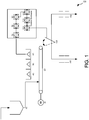
Fig. 1 illustrates an example of an arrangement for a sorting machine. The sorting machine may include a feed mechanism, an electromagnetic source/detector array, and a control enclosure. The control enclosure may include an analog to digital signal conversion and signal analysis system, and a diverter array system connected to the control enclosure. - A
sorter 100 may include a Teflon-lined, steep-sided feed bin suitable for accepting clay orrocky material feed 10, delivering material to a sortingconveyor 20 driven byvariable speed motor 30. Material present on thesorting conveyor 20 may be detected by a scanning laser 40 which activates an electromagnetic energy source array 50. Consequent electromagnetic radiation absorption, reflectance or backscatter from the material present in the source energy field may be detected by a detector array 60. Analogue signals from the detector array may then be converted by analogue todigital signal converter 70 to digital form and be passed to a digitalsignal processing stage 80 where Fourier Analysis is performed to generate a discrete power spectrum analyzed by frequency or wavelength. - Discrete power spectrum data thus generated may then be compared using pattern recognition algorithms to determine the mineral content. Results of the pattern recognition algorithm may then be compared to pre-determined results in an embedded
industrial computer 90. A diverter comprising relay/solenoid 110,actuator 120 andgate 130 may be controlled by the embeddedindustrial computer 90 via theprogrammable logic controller 100. Material with a recognized chemical composition above a certain pre-set value may be diverted to aproduct chute 140. Material with a recognized chemical composition below a certain pre-set value may be diverted to awaste chute 150. -
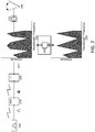
Fig. 2 illustrates an example of a control system with embedded pattern recognition and discrimination algorithms. The control system may include an analogue to digital conversion stage, a digital signal processing stage, a pattern recognition stage, comparator stage and a diverter array control stage. - Signals of arbitrary waveform, wavelength and frequency from a
detector array 200 may be converted by analog todigital signal converter 210. Digital signals from theconverter 210 may be passed to a Fourier Analysis stage where spectral data of amplitude/frequency or amplitude/wavelength format may be generated by Fast Fourier Transform implemented on a field programmable gate array (FPGA) 220 or other suitable device (e.g. a digital signal processor (DSP), application specific IC (ASIC), microcontroller, etc.). Arbitrary power spectra generated 230 in theFourier Analysis stage 220 may be compared to previously determined and known spectra 260. Spectra of desired material may be recognized bypattern recognition algorithm 240 running on an embeddedcomputer 250. Recognition of desired material may result in "accept" instructions being passed from the embeddedcomputer 250 to thediverter array 280 via aprogrammable logic controller 270 or other suitable device (e.g. FPGA, DSP, ASIC, microcontroller, etc.). Recognition of undesired material may result in "reject" instructions being passed to adiverter array 280. The equivalency between like components inFIGS. 2 and1 are evident -detector array 200 ofFIG. 2 is equivalent to detector array 60 inFIG. 1 ;signal converter 210 to signalconverter 70; embeddedcomputer 250 tocomputer 90;diverter array 280 todiverter gate 130;PLC 270 toPLC 100 and so on. - Referring now to the pattern recognition algorithm in more detail, the concepts of recognition and identification as used in biometric security are introduced. Automated digital signal analysis is conventionally applied for pattern recognition using an exact matched, or identified, signal. In spectrum matching, both wavelength and amplitude, or frequency and amplitude of an arbitrary power spectrum are to be matched. Traditional pattern matching requires comparison of every inbound spectrum to the sample spectrum to achieve an exact match and is computationally very intensive and time consuming and therefore not practical in high-speed mineral recognition applications. Recognition is hereby differentiated from identification, or matching, for the purpose of the present system. As used in biometric security, for instance, recognition is the verification of a claim of identity, while identification is the determination of identity. These scenarios loosely correspond to the use of sensor telemetry for classification (e.g., sorting applications in the field) and characterization (e.g., analytical operations in the laboratory). To build further intuition, the biometric identification/recognition scenario will be further elucidated:
- In the laboratory, a sample might be subjected to, for example, an X-ray Fluorescence sensor for analytic purposes. In the mining practice of interest, a spectral pattern is created in the lab using analytical procedures (i.e., samples from the deposit of interest are characterized or identified using analytical procedures in the lab). This is to say that the objective of the sampling is to yield the most accurate and precise result: a sensor-based assay. In this way the identity of a mineral sample as determined by sensor-based techniques is a priori determined. This template is programmed into field units so that results from new samples can be compared to it in quasi-real time.
- The biometric analogy might go as follows: You are returning to your home country at one of its major international airports and have the option of using a kiosk equipped with an iris scanner. You simply approach the kiosk and present only your eye for examination by the scanner. The kiosk reads your iris and prints out a receipt with your name on it for you to present to a customs agent. The kiosk has clearly searched for a closest match to the sample you just provided, from a database of templates. You have been identified by the kiosk. Leaving aside the question of whether or not this is good security practice, it is clear that the kiosk is programmed to minimize the possibility of identity fraud (i.e., the incidence of false acceptance).
- In the field, samples are to be analyzed quickly-in quasi-real time-in order to produce economically viable results. There is neither time nor, as it turns out, need for exactitude in matching. A sample is to simply match the a priori pattern within a pre-determined tolerance; it is then recognized as a positive instance, or else it is classified as a negative instance.
- It is therefore necessary only to recognize the emerging spectral pattern, based on the a priori identification described above, in time to make a classification decision.
- The biometric analogy might go as follows: You are returning to your home country at one of its major international airports and have the option of using a kiosk equipped with an iris scanner. You approach the kiosk and present your passport, thereby making an identity claim. You then present your eye for examination by the scanner. The kiosk reads your iris and compares the sample to a stored template (derived, perhaps, from information encrypted in your passport). Identity has been rapidly confirmed by recognition of the subject based on a priori knowledge of the subject content. This is analogous to the pattern recognition algorithm deployed in various embodiments of the present invention.
- The advanced pattern recognition methodology deployed involves pattern learning (or classification) of absorbed, reflected or backscattered energy from the irradiation of previously characterized mineral samples and pattern recognition comprising fuzzy analysis and resource-bounded matching of absorption, reflectance or backscattered spectra from newly irradiated mineral samples through a trained conditional random field (CRF) algorithm. The algorithms that match of absorption, reflectance or backscattered spectra may be resource-bounded, meaning that energy physics determines when measurement of a sample is complete.
- Referring now to the CRF algorithm, CRF involves the "training" of the random field on known spectra, as well as the use of the random field under resource bounded conditions to rapidly recognize new spectra similar to the "trained" spectrum. In contrast to an ordinary matching algorithm which predicts a result for a single sample without regard to "neighboring" samples, the CRF algorithm deployed predicts a likely sequence of results for sequences of input samples analysed. Let X be an array observed spectral measurements with Y a corresponding array of random output spectra. Let


-
Fig. 2 references therefore a pattern recognition algorithm of the conditional random field type, using back-propagation when in the training mode to define matching coefficients e for the conditional random field, which additionally incorporates pseudo-random sampling, and boundary detection comprising confirmation of the spectral upper and lower bounds. The system is trained to recognize the presence of a range of typical mineral constituents in a matrix such as iron, aluminium, silica and magnesium present in a sample which is moving with reference to the sensor, calculate the specific and total concentration of each element in the sample and compare it to the pre-defined spectrum of known material obtained during the "training" phase of the algorithm development. - Other pattern recognition algorithms such as inter alia brute-force, nearest-neighbour, peak matching etc. may be used. As such, embodiments of the present invention are not limited to the particular algorithm described. For example, the peak frequencies from a few samples with certain amplitudes may be identified, and then each sample may be analyzed for peaks near those frequencies and above a certain amplitude.
-
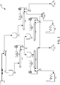
Fig. 3 illustrates an example of an arrangement of a sorting system in an open pit mining application. Embodiments depicted inFig. 3 may be used, for example to classify a pyrometallurgical process feed, a hydrometallurgical process feed and a waste product simultaneously from the same deposit. Typical bulk open pit mining equipment delivers unblended mineral feed to an ore sorting facility comprising arrays of electromagnetic sorting machines described. Saprolitic material produced by the sorting facility is delivered topyrometallurgical plant 480. Limonitic material simultaneously recovered by the sorting facility is delivered tohydrometallurgical plant 550. Waste material simultaneously recovered by the sorting facility is delivered to wastepiles -
Unblended laterite material 310 from the open pit may be delivered bytruck 320 tocoarse separator 330. Fine fractions fromseparator 330 underflow may be passed to finesorter feed bin 340 where material may be held prior to delivery to sortingconveyor 350. Material travelling on the sortingconveyor 350 may be scanned by an array ofelectromagnetic sensors 360. Results from theelectromagnetic sensors 360 may be passed tocontroller 370 which compares the sensor results to pre-set values and may instruct thediverter 380 to divert the material according to its chemical content. High iron limonitic material may be diverted tolimonite sorter 490. High silica saprolitic material may be diverted to saprolitesorter feed bin 560. - High iron limonitic material from the sorting
conveyor 350 may be passed to the limonitesorter feed bin 490 where material is held prior to delivery to sortingconveyor 500. Material traveling on the sortingconveyor 500 may be scanned by an array ofelectromagnetic sensors 510. Results from theelectromagnetic sensors 510 may be passed tocontroller 520 which compares the sensor results to pre-set values and instructsdiverter 530 to divert the material according to its chemical content. Material not suitable for treatment is diverted to thewaste pile 540. Limonitic material suitable for treatment is passed via the limonite product conveyor to thehydrometallurgical facility 550. - Similarly high silica saprolitic material from the sorting
conveyor 350 may be passed to saprolitesorter feed bin 560 where material may be held prior to delivery to sortingconveyor 570. Material travelling on the sorting conveyor may be scanned by an array ofelectromagnetic sensors 580. Results from theelectromagnetic sensors 580 may be passed to thecontroller 590 which compares the sensor results to pre-set values and instructs thediverter 600 to divert the material according to its chemical content. Material not suitable for treatment is diverted to thewaste pile 540. Saprolitic material suitable for treatment is passed via thesaprolite product conveyor 460 topyrometallurgical facility 480. - Coarse fractions from the
separator 330 overflow may be passed to coarsesorter feed bin 410 where material may be held prior to delivery to the sorting conveyor. Material traveling on sortingconveyor 420 may scanned by an array ofelectromagnetic sensors 430. Results from the array ofelectromagnetic sensors 430 may be passed tocontroller 440 which compares the sensor results to pre-set values and instructs thediverter array 450 to divert the material according to its chemical content. High nickel saprolitic material may be diverted tosaprolite product conveyor 460. Low nickel, high iron and high silica material may be diverted to thewaste pile 470. Note that some elements may be combined together, such as a single controller that performs comparisons and instructs diverters. -
Fig. 4 is a flowchart having an example set of instructions for determining mineral content. The operations can be performed by various components such as processors, controllers, and/or other components. In receivingoperation 410, response data from a mineral sample is received. The response data may be detected by a scanner that detects the response of the mineral sample to electromagnetic radiation (i.e., reflected or absorbed energy). An analog to digital converter may digitize the response data. - In determining
operation 420, the spectral characteristics of the mineral sample may be determined. A spectral analysis may be performed on the response data to determine characteristics of the mineral sample. Characteristics may include frequency, wavelength, and/or amplitude. In some embodiments, characteristics include other user-defined characteristics. - In identifying
operation 430, a composition of the mineral sample is identified by comparing the characteristics of the mineral sample to characteristics of known mineral samples. Pattern matching algorithms may be used in identifying the composition. - In assigning
operation 440, a composition value is assigned to the mineral sample. - In
decision operation 450, it is determined whether the composition value is within a predetermined tolerance of composition values. Inreject operation 460, the assigned value of the composition is not within the predetermined tolerance (i.e., the characteristics do not fit with in a pattern), and, thus, the mineral sample is diverted to a waste pile. In acceptoperation 470, the assigned value of the composition is within the predetermined tolerance (i.e., the characteristics fit within a pattern), and thus, the mineral sample is diverted to a hydrometallurgical or pyrometallurgical process. - Embodiments of the present invention include various steps and operations, which have been described above. A variety of these steps and operations may be performed by hardware components or may be embodied in machine-executable instructions, which may be used to cause a general-purpose or special-purpose processor programmed with the instructions to perform the steps. Alternatively, the steps may be performed by a combination of hardware, software, and/or firmware. As such,
Fig. 5 is an example of acomputer system 500 with which embodiments of the present invention may be utilized. According to the present example, the computer system includes abus 510, at least oneprocessor 520, at least onecommunication port 530, amain memory 540, aremovable storage media 550, a read onlymemory 560, and amass storage 570. - Processor(s) 520 can be any known processor, such as, but not limited to, an Intel® Itanium® or Itanium 2® processor(s); AMD® Opteron® or Athlon MP® processor(s); or Motorola® lines of processors. Communication port(s) 530 can be any of an RS-232 port for use with a modem-based dialup connection, a 10/100 Ethernet port, or a Gigabit port using copper or fiber. Communications may also take place over wireless interfaces. Communication port(s) 530 may be chosen depending on a network such as a Local Area Network (LAN), Wide Area Network (WAN), or any network to which the
computer system 500 connects. -
Main memory 540 can be Random Access Memory (RAM) or any other dynamic storage device(s) commonly known in the art. Read onlymemory 560 can be any static storage device(s) such as Programmable Read Only Memory (PROM) chips for storing static information such as instructions forprocessor 520. -
Mass storage 570 can be used to store information and instructions. For example, hard disks such as the Adaptec® family of SCSI drives, an optical disc, an array of disks such as RAID, such as the Adaptec family of RAID drives, or any other mass storage devices may be used. -
Bus 510 communicatively couples processor(s) 520 with the other memory, storage and communication blocks.Bus 510 can be a PCI /PCI-X or SCSI based system bus depending on the storage devices used. -
Removable storage media 550 can be any kind of external hard-drives, floppy drives, IOMEGA® Zip Drives, Compact Disc - Read Only Memory (CD-ROM), Compact Disc - Re-Writable (CD-RW), and/or Digital Video Disk - Read Only Memory (DVD-ROM). - Although not required, aspects of the invention may be practiced in the general context of computer-executable instructions, such as routines executed by a general-purpose data processing device, e.g., a server computer, wireless device or personal computer. Those skilled in the relevant art will appreciate that aspects of the invention can be practiced with other communications, data processing, or computer system configurations, including: Internet appliances, hand-held devices (including personal digital assistants (PDAs)), wearable computers, all manner of cellular or mobile phones (including Voice over IP (VoIP) phones), dumb terminals, multi-processor systems, microprocessor-based or programmable consumer electronics, set-top boxes, network PCs, mini-computers, mainframe computers, and the like.
- Aspects of the invention can be embodied in a special purpose computer or data processor that is specifically programmed, configured, or constructed to perform one or more of the computer-executable instructions explained in detail herein. While aspects of the invention, such as certain functions, are described as being performed exclusively on a single device, the invention can also be practiced in distributed environments where functions or modules are shared among disparate processing devices, which are linked through a communications network, such as a Local Area Network (LAN), Wide Area Network (WAN), or the Internet. In a distributed computing environment, program modules may be located in both local and remote memory storage devices.
- Aspects of the invention may be stored or distributed on tangible computer-readable media, including magnetically or optically readable computer discs, hardwired or preprogrammed chips (e.g., EEPROM semiconductor chips), nanotechnology memory, biological memory, or other data storage media. Alternatively, computer implemented instructions, data structures, screen displays, and other data under aspects of the invention may be distributed over the Internet or over other networks (including wireless networks), on a propagated signal on a propagation medium (e.g., an electromagnetic wave(s), a sound wave, etc.) over a period of time, or they may be provided on any analog or digital network (packet switched, circuit switched, or other scheme).
- As one of ordinary skill in the art will appreciate based on the detailed description provided herein, and various novel concepts are realized, some of which are listed below:
- 1. A source-detector type electromagnetic sorting system comprising:
- a. a device for the introduction of mineral feed to the sensor;
- b. a device for the generation of a range of excitation beams;
- c. a scanner for the detection of resulting reflected, absorbed, or backscattered energy;
- d. an analog to digital converter to digitize both the signal in (c);
- e. a software program for signal analysis, data recording, and process control;
- f. a control system for processing signal outputs; and
- g. a diverter connected to the control system for the diversion of minerals.
- 2. The source-detector type electromagnetic sorting system of claim 1, wherein the software program comprises:
- a. a subroutine to convert incoming analog signals to digital format
- b. a subroutine to express spectral content of the converted analog signal
- c. a subroutine to perform spectral analysis on both digitized signals in 1(c), determining frequency or wavelength content and amplitude;
- d. a subroutine to calibrate the system;
- e. a subroutine to record the response data in (b) and (c) along with additional user defined fields;
- f. a subroutine to compare spectral response data to previously recorded spectral data from samples of known composition by means of conditional random field analysis;
- g. a subroutine to generate a sort signal based on the comparison in (f); and
- h. a graphical user interface to control operation and data recording.
- 3. A method of determining the spectral response of a mineral sample under irradiation by electromagnetic means using said system comprising:
- a. providing said source detector sensing and sorting system;
- b. exposing said sensor to a mineral sample;
- c. converting the spectral response of said mineral sample to digital format by means of the software program in 1(e);
- d. measuring the spectral response of said mineral sample to said sensor by means of the software program in 1(e); and
- e. converting the measured response (c) into a power spectrum by means of the software program described in 1(e).
- f. assigning an appropriate threshold of acceptance for spectral responses above a certain pre-determined value and 'training' the algorithm to recognize those responses
- 4. A method of determining the mineral composition of an unknown sample using said sensor comprising:
- a. providing said system;
- b. measuring the spectral response due to the unknown sample;
- c. using the software program described in 1(e) to compare the measured data in (b) to previously recorded response data from samples of known grade as describe in 3; and
- d. using said software program to assign a compositional value to the unknown sample based on the comparison in (c).
- 5. A method of discriminating mineral samples based on spectral response using said sensor comprising:
- a. providing said system;
- b. determining characteristic spectral response of the mineral sample as described in 3 and 4;
- c. using the software program in 1(e) to compare the values determined in (b) to predefined spectra of previously characterized mineral samples by means of the conditional random field algorithm described; and
- d. using the control system described in 1(f) to control the diverter system based upon results of the comparison described in (c).
- 6. A method of automatically rejecting or accepting mineral samples based on spectral response using the system of claim 1 comprising the steps of:
- a. providing said system;
- b. discriminating between sample materials;
- c. using the software program in 1(e) to generate a sort decision based on the discrimination in (b); and
- d. effecting the sort based on the decision in (c) by means of the sorting mechanism described in 1 and 2.
- Unless the context clearly requires otherwise, throughout the description and the claims, the words "comprise," "comprising," and the like are to be construed in an inclusive sense, as opposed to an exclusive or exhaustive sense; that is to say, in the sense of "including, but not limited to." As used herein, the terms "connected," "coupled," or any variant thereof means any connection or coupling, either direct or indirect, between two or more elements; the coupling or connection between the elements can be physical, logical, or a combination thereof. Additionally, the words "herein," "above," "below," and words of similar import, when used in this application, refer to this application as a whole and not to any particular portions of this application. Where the context permits, words in the above Detailed Description using the singular or plural number may also include the plural or singular number respectively. The word "or," in reference to a list of two or more items, covers all of the following interpretations of the word: any of the items in the list, all of the items in the list, and any combination of the items in the list.
- The above Detailed Description of examples of the invention is not intended to be exhaustive or to limit the invention to the precise form disclosed above. While specific examples for the invention are described above for illustrative purposes, various equivalent modifications are possible within the scope of the invention, as those skilled in the relevant art will recognize. For example, while processes or blocks are presented in a given order, alternative implementations may perform routines having steps, or employ systems having blocks, in a different order, and some processes or blocks may be deleted, moved, added, subdivided, combined, and/or modified to provide alternative or subcombinations. Each of these processes or blocks may be implemented in a variety of different ways. Also, while processes or blocks are at times shown as being performed in series, these processes or blocks may instead be performed or implemented in parallel, or may be performed at different times. Further any specific numbers noted herein are only examples: alternative implementations may employ differing values or ranges.
- The teachings of the invention provided herein can be applied to other systems, not necessarily the system described above. The elements and acts of the various examples described above can be combined to provide further implementations of the invention. Some alternative implementations of the invention may include not only additional elements to those implementations noted above, but also may include fewer elements. Aspects of the invention can be modified, if necessary, to employ the systems, functions, and concepts of the various references described above to provide yet further implementations of the invention.
- These and other changes can be made to the invention in light of the above Detailed Description. While the above description describes certain examples of the invention, and describes the best mode contemplated, no matter how detailed the above appears in text, the invention can be practiced in many ways. Details of the system may vary considerably in its specific implementation. As noted above, particular terminology used when describing certain features or aspects of the invention should not be taken to imply that the terminology is being redefined herein to be restricted to any specific characteristics, features, or aspects of the invention with which that terminology is associated. In general, the terms used in the following claims should not be construed to limit the invention to the specific examples disclosed in the specification, unless the above Detailed Description section explicitly defines such terms. Accordingly, the actual scope of the invention encompasses not only the disclosed examples, but also all equivalent ways of practicing or implementing the invention under the claims.
Claims (13)
- A method of sorting a stream of unblended minerals, comprising:irradiating an unblended mineral sample (310) with electromagnetic energy to thereby generate reflected, absorbed, or backscattered energy from the unblended mineral sample;measuring the reflected, absorbed or backscattered energy generated by irradiating the unblended mineral sample with a sensor (60, 200, 360) configured to measure reflected, absorbed or backscattered energy;determining spectral characteristics of the unblended mineral sample by performing spectral analysis on the measured reflected, absorbed or backscattered energy generated by irradiating the unblended mineral sample, wherein the spectral characteristics include at least one of frequency content, wavelength content, or amplitude of the response data;identifying a composition of the unblended mineral sample by comparing the spectral characteristics of the unblended mineral sample to previously developed spectral characteristics of samples of known composition, wherein the spectral characteristics of samples of known composition are developed using at least one of: conditional random field algorithms, Bayesian network, one or more Markov models, neural networks, or fuzzy logic techniques; andgenerating a sort decision for the unblended mineral sample based on the comparison, wherein the sort decision is used in diverting the mineral sample to a desired destination.
- The method of claim 1 further comprising collecting spectral response data from a series of mineral samples irradiated with electromagnetic energy and exposed to a sensor to develop the spectral characteristics of samples of known composition.
- The method of claim 1 wherein identifying a composition of the unblended mineral sample includes assigning a compositional value to the unblended mineral sample based on the comparison.
- The method of claim 3 wherein the unblended mineral sample is diverted to an accept pile when the compositional value is within a predetermined variation of the previously developed spectral characteristics.
- The method of claim 1 wherein comparing the spectral characteristics of the unblended mineral sample to previously developed spectral characteristics of samples of known composition includes matching the spectral characteristics of the unblended mineral sample to previously developed pattern sets.
- The method of claim 1 wherein the method further comprises:extracting the unblended mineral ore from a mine bench or pit using a mechanical excavator or similar earthmoving device;delivering the unblended mineral ore to a haul truck or conveyor belt using the excavator;transporting the unblended mineral ore to a first mineral sorting system (340, 350, 360, 370, 380), the first mineral sorting system that performs the steps of irradiating an unblended mineral sample with electromagnetic energy, measuring the reflected, absorbed or backscattered energy, determining spectral characteristics of the unblended mineral sample, identifying a composition of the unblended mineral sample:generating the sort decision by classifying the unblended mineral ore, based on the comparison, into a first mineral product and a second mineral product;transporting the first mineral product to a second mineral sorting system (560, 570, 580, 590, 600), the second mineral sorting system configured to:apply electromagnetic radiation to the first mineral product;detect a response of the first mineral product to the electromagnetic radiation, andcompare the response data to previously determined response data of samples of known composition to determine the composition of the first mineral product;classifying the first mineral product, based on the comparison, into a final first mineral product and waste product;transporting the second mineral product to a third mineral sorting system (490, 500, 510, 520, 530), the third mineral sorting system configured to:apply electromagnetic radiation to the second mineral product;detect a response of the second mineral product to the electromagnetic radiation, andcompare the response data to previously determined response data of samples of known composition to determine the composition of the second mineral product;classifying the second mineral product, based on the comparison, into a final second mineral product and waste product.
- The method of claim 6, wherein:the final first mineral product is conditioned for pyrometallurgical treatment,the final second mineral product is conditioned for hydrometallurgical treatment, andthe waste product is conditioned for disposal as a waste product.
- At least one tangible computer-readable medium carrying instructions which, when executed by at least one processor, causes the system of claim 11 to carry out the steps of the method of claim 1.
- The at least one tangible computer-readable medium of claim 8, wherein the unblended mineral sample is a laterite, and wherein the sort decision is used to divert the mineral sample to one of: a hydrometallurgical process, a pyrometallurgical process, or a waste pile.
- The at least one tangible computer-readable medium of claim 8, wherein the instructions, which when executed by the at least one processor, further causes the following method step to be performed:
transporting the unblended mineral sample into a source field. - A system for sorting minerals, comprising:a device configured to introduce an unblended mineral sample (310) to a sensor;a device (50) configured to generate electromagnetic energy to apply to the unblended mineral sample and thereby generate reflected, absorbed or backscattered energy from the unblended mineral sample;a sensor (60, 200, 360) configured to measure the reflected, absorbed or backscattered energy generated by applying electromagnetic energy to the unblended mineral sample;a means (220) configured to determine spectral characteristics of the unblended mineral sample by performing spectral analysis on the measured reflected, absorbed or backscattered energy generated by irradiating the unblended mineral sample, wherein the spectral characteristics include at least one of frequency content, wavelength content, or amplitude of the response data;a means (250) configured to identify a composition of the unblended mineral sample by comparing the spectral characteristics of the unblended mineral sample to previously developed spectral characteristics of samples of known composition, wherein the spectral characteristics of samples of known composition are developed using at least one of: conditional random field algorithms, Bayesian network, one or more Markov models, neural networks, or fuzzy logic techniques; anda means (250) configured to generate a sort decision for the unblended mineral sample based on the comparison, wherein the sort decision is used in diverting the mineral sample to a desired destination.
- The system of claim 11 further comprising:an analog to digital converter (70, 210) to digitize the measured reflected, absorbed or backscattered energy;a control system (250) to process signal outputs; anda diverter (280) coupled to the control system for the diversion of the mineral samples.
- The system of claim 11 further comprising a graphical user interface to control operation and record data.
Priority Applications (1)
| Application Number | Priority Date | Filing Date | Title |
|---|---|---|---|
| EP20160983.1A EP3734257A1 (en) | 2012-05-01 | 2013-04-30 | Sorting materials using pattern recognition, such as upgrading nickel laterite ores through electromagnetic sensor-based methods |
Applications Claiming Priority (4)
| Application Number | Priority Date | Filing Date | Title |
|---|---|---|---|
| US201261640749P | 2012-05-01 | 2012-05-01 | |
| US13/538,931 US8958905B2 (en) | 2011-06-29 | 2012-06-29 | Extracting mined ore, minerals or other materials using sensor-based sorting |
| US13/830,453 US9316537B2 (en) | 2011-06-29 | 2013-03-14 | Sorting materials using a pattern recognition, such as upgrading nickel laterite ores through electromagnetic sensor-based methods |
| PCT/CA2013/050330 WO2013163756A1 (en) | 2012-05-01 | 2013-04-30 | Sorting materials using pattern recognition, such as upgrading nickel laterite ores through electromagnetic sensor-based methods |
Related Child Applications (2)
| Application Number | Title | Priority Date | Filing Date |
|---|---|---|---|
| EP20160983.1A Division EP3734257A1 (en) | 2012-05-01 | 2013-04-30 | Sorting materials using pattern recognition, such as upgrading nickel laterite ores through electromagnetic sensor-based methods |
| EP20160983.1A Division-Into EP3734257A1 (en) | 2012-05-01 | 2013-04-30 | Sorting materials using pattern recognition, such as upgrading nickel laterite ores through electromagnetic sensor-based methods |
Publications (3)
| Publication Number | Publication Date |
|---|---|
| EP2844987A1 EP2844987A1 (en) | 2015-03-11 |
| EP2844987A4 EP2844987A4 (en) | 2015-12-09 |
| EP2844987B1 true EP2844987B1 (en) | 2020-04-15 |
Family
ID=49514152
Family Applications (2)
| Application Number | Title | Priority Date | Filing Date |
|---|---|---|---|
| EP20160983.1A Withdrawn EP3734257A1 (en) | 2012-05-01 | 2013-04-30 | Sorting materials using pattern recognition, such as upgrading nickel laterite ores through electromagnetic sensor-based methods |
| EP13784189.6A Active EP2844987B1 (en) | 2012-05-01 | 2013-04-30 | Sorting materials using pattern recognition, such as upgrading nickel laterite ores through electromagnetic sensor-based methods |
Family Applications Before (1)
| Application Number | Title | Priority Date | Filing Date |
|---|---|---|---|
| EP20160983.1A Withdrawn EP3734257A1 (en) | 2012-05-01 | 2013-04-30 | Sorting materials using pattern recognition, such as upgrading nickel laterite ores through electromagnetic sensor-based methods |
Country Status (4)
| Country | Link |
|---|---|
| EP (2) | EP3734257A1 (en) |
| AU (3) | AU2013255048B2 (en) |
| CA (1) | CA2871627C (en) |
| WO (1) | WO2013163756A1 (en) |
Families Citing this family (15)
| Publication number | Priority date | Publication date | Assignee | Title |
|---|---|---|---|---|
| US11219927B2 (en) | 2011-06-29 | 2022-01-11 | Minesense Technologies Ltd. | Sorting materials using pattern recognition, such as upgrading nickel laterite ores through electromagnetic sensor-based methods |
| EP3698889A1 (en) | 2011-06-29 | 2020-08-26 | Minesense Technologies Ltd. | Extracting mined ore, minerals or other materials using sensor-based sorting |
| US9316537B2 (en) | 2011-06-29 | 2016-04-19 | Minesense Technologies Ltd. | Sorting materials using a pattern recognition, such as upgrading nickel laterite ores through electromagnetic sensor-based methods |
| AU2013255051B2 (en) | 2012-05-01 | 2016-05-19 | Minesense Technologies Ltd. | High capacity cascade-type mineral sorting machine and method |
| US9884346B2 (en) | 2014-07-21 | 2018-02-06 | Minesense Technologies Ltd. | High capacity separation of coarse ore minerals from waste minerals |
| EP4219843A1 (en) | 2014-07-21 | 2023-08-02 | Minesense Technologies Ltd. | Mining shovel with compositional sensors |
| FR3074296B1 (en) * | 2017-11-28 | 2019-12-27 | Nge | METHOD OF ANALYSIS AND TREATMENT OF EXCAVATED LAND |
| RU2687213C1 (en) * | 2018-04-27 | 2019-05-07 | Федеральное государственное бюджетное учреждение науки Институт горного дела Дальневосточного отделения Российской академии наук | Method of open development of complex structural deposits of solid minerals |
| RU2682854C1 (en) * | 2018-05-14 | 2019-03-21 | Федеральное государственное бюджетное образовательное учреждение высшего образования "Воронежский государственный лесотехнический университет имени Г.Ф. Морозова" | Device for seeds sorting |
| RU2687509C1 (en) * | 2018-07-09 | 2019-05-14 | Федеральное государственное бюджетное образовательное учреждение высшего образования "Воронежский государственный лесотехнический университет имени Г.Ф. Морозова" | Seed sorting device |
| RU2714420C1 (en) * | 2019-08-08 | 2020-02-14 | Федеральное государственное бюджетное учреждение науки Хабаровский Федеральный исследовательский центр Дальневосточного отделения Российской академии наук (ХФИЦ ДВО РАН) | Method for development of complex-structure solid mineral deposits |
| CN114585453A (en) * | 2019-09-23 | 2022-06-03 | 保利斯科有限公司 | Classification method |
| CN111859811B (en) * | 2020-07-30 | 2021-03-16 | 中国地质科学院矿产资源研究所 | Ore formation prediction method and system based on fuzzy logic and machine learning |
| BR102022002312B1 (en) * | 2022-02-07 | 2023-02-07 | David Christopher Michael Madderson | INTEGRATED MINE PLANNING AND PROCESSING PROCESS, REAL-TIME DATA COLLECTION, PRE-CONCENTRATION VIA SENSOR ORE SORTING (DRY) TOGETHER WITH A DRY COMMINUTION FLOWCHART COMBINED WITH A WET FINAL CONCENTRATION FLOWCHART |
| WO2024040282A1 (en) * | 2022-08-23 | 2024-02-29 | Newcrest Mining Limited | Selective processing |
Family Cites Families (6)
| Publication number | Priority date | Publication date | Assignee | Title |
|---|---|---|---|---|
| US3747755A (en) * | 1971-12-27 | 1973-07-24 | Massachusetts Inst Technology | Apparatus for determining diffuse and specular reflections of infrared radiation from a sample to classify that sample |
| US6753957B1 (en) * | 2001-08-17 | 2004-06-22 | Florida Institute Of Phosphate Research | Mineral detection and content evaluation method |
| EA010956B1 (en) * | 2004-09-07 | 2008-12-30 | Петромодел Эхф | Apparatus and method for analysis of size, form and angularity and for compositional analysis of mineral and rock particles |
| CA2629408A1 (en) * | 2008-05-01 | 2009-11-01 | Andrew S. Bamber | Induction balance sensor |
| CN102892521A (en) * | 2010-03-23 | 2013-01-23 | 技术资源有限公司 | Sorting mined material on the basis of two or more properties of material |
| US20130169961A1 (en) * | 2010-03-29 | 2013-07-04 | Datatrace Dna Pty Limited | System for classification of materials using laser induced breakdown spectroscopy |
-
2013
- 2013-04-30 CA CA2871627A patent/CA2871627C/en active Active
- 2013-04-30 WO PCT/CA2013/050330 patent/WO2013163756A1/en active Application Filing
- 2013-04-30 EP EP20160983.1A patent/EP3734257A1/en not_active Withdrawn
- 2013-04-30 AU AU2013255048A patent/AU2013255048B2/en active Active
- 2013-04-30 EP EP13784189.6A patent/EP2844987B1/en active Active
-
2017
- 2017-02-27 AU AU2017201320A patent/AU2017201320B2/en active Active
-
2019
- 2019-06-10 AU AU2019204043A patent/AU2019204043A1/en not_active Abandoned
Non-Patent Citations (1)
| Title |
|---|
| None * |
Also Published As
| Publication number | Publication date |
|---|---|
| AU2017201320B2 (en) | 2019-03-14 |
| AU2013255048B2 (en) | 2016-12-08 |
| EP3734257A1 (en) | 2020-11-04 |
| WO2013163756A1 (en) | 2013-11-07 |
| EP2844987A1 (en) | 2015-03-11 |
| CA2871627A1 (en) | 2013-11-07 |
| AU2013255048A1 (en) | 2014-11-13 |
| AU2019204043A1 (en) | 2019-06-27 |
| AU2017201320A1 (en) | 2017-03-16 |
| CA2871627C (en) | 2017-06-20 |
| EP2844987A4 (en) | 2015-12-09 |
Similar Documents
| Publication | Publication Date | Title |
|---|---|---|
| US10259015B2 (en) | Sorting materials using pattern recognition, such as upgrading nickel laterite ores through electromagnetic sensor-based methods | |
| AU2017201320B2 (en) | Sorting materials using pattern recognition, such as upgrading nickel laterite ores through electromagnetic sensor-based methods | |
| US11219927B2 (en) | Sorting materials using pattern recognition, such as upgrading nickel laterite ores through electromagnetic sensor-based methods | |
| AU2018203576B2 (en) | High Capacity Cascade-Type Mineral Sorting Machine and Method | |
| Murphy et al. | Underground preconcentration by ore sorting and coarse gravity separation | |
| Michaux et al. | How to set up and develop a geometallurgical program | |
| Fu et al. | Quantitative ore texture analysis with convolutional neural networks | |
| Perez et al. | Lithological classification based on Gabor texture image analysis | |
| Maier et al. | A survey of the state of the art in sensor-based sorting technology and research | |
| de Sousa | Assessment of separation efficiency in mineral processing using the ultimate upgrading concept-a holistic window to integrate mineral liberation data | |
| Zhang | Assessment of dual-energy X-ray transmission image analysis process on sulphide ore and coal cases | |
| Robben et al. | X-ray transmission sorting of tungsten ore | |
| Müller et al. | Sorting of Construction and Demolition Waste for coarse fractions | |
| Bacchuwar | X-Ray Computed Tomography for Analysis of Gangue Rejection in Gravity Preconcentration of Low Grade Sulfide Ores | |
| Oghazi | Traceability in continuous ore beneficiation processes using process mineralogy signatures | |
| Duffy et al. | Bulk ore sorting for pre-concentration: what, how, and why? | |
| Fina Ferreira et al. | An Automated Mineralogy Derived Criterion for Clustering Ore Samples for Mineral Liberation Studies |
Legal Events
| Date | Code | Title | Description |
|---|---|---|---|
| PUAI | Public reference made under article 153(3) epc to a published international application that has entered the european phase |
Free format text: ORIGINAL CODE: 0009012 |
|
| 17P | Request for examination filed |
Effective date: 20141030 |
|
| AK | Designated contracting states |
Kind code of ref document: A1 Designated state(s): AL AT BE BG CH CY CZ DE DK EE ES FI FR GB GR HR HU IE IS IT LI LT LU LV MC MK MT NL NO PL PT RO RS SE SI SK SM TR |
|
| AX | Request for extension of the european patent |
Extension state: BA ME |
|
| DAX | Request for extension of the european patent (deleted) | ||
| RA4 | Supplementary search report drawn up and despatched (corrected) |
Effective date: 20151105 |
|
| RIC1 | Information provided on ipc code assigned before grant |
Ipc: G01N 21/85 20060101ALI20151030BHEP Ipc: G01N 23/00 20060101AFI20151030BHEP Ipc: B07B 13/18 20060101ALI20151030BHEP Ipc: G01N 33/24 20060101ALI20151030BHEP Ipc: E21C 41/30 20060101ALI20151030BHEP |
|
| STAA | Information on the status of an ep patent application or granted ep patent |
Free format text: STATUS: EXAMINATION IS IN PROGRESS |
|
| 17Q | First examination report despatched |
Effective date: 20190423 |
|
| GRAP | Despatch of communication of intention to grant a patent |
Free format text: ORIGINAL CODE: EPIDOSNIGR1 |
|
| STAA | Information on the status of an ep patent application or granted ep patent |
Free format text: STATUS: GRANT OF PATENT IS INTENDED |
|
| INTG | Intention to grant announced |
Effective date: 20191029 |
|
| GRAS | Grant fee paid |
Free format text: ORIGINAL CODE: EPIDOSNIGR3 |
|
| GRAA | (expected) grant |
Free format text: ORIGINAL CODE: 0009210 |
|
| STAA | Information on the status of an ep patent application or granted ep patent |
Free format text: STATUS: THE PATENT HAS BEEN GRANTED |
|
| AK | Designated contracting states |
Kind code of ref document: B1 Designated state(s): AL AT BE BG CH CY CZ DE DK EE ES FI FR GB GR HR HU IE IS IT LI LT LU LV MC MK MT NL NO PL PT RO RS SE SI SK SM TR |
|
| REG | Reference to a national code |
Ref country code: CH Ref legal event code: EP |
|
| REG | Reference to a national code |
Ref country code: DE Ref legal event code: R096 Ref document number: 602013067973 Country of ref document: DE |
|
| REG | Reference to a national code |
Ref country code: IE Ref legal event code: FG4D |
|
| REG | Reference to a national code |
Ref country code: AT Ref legal event code: REF Ref document number: 1257911 Country of ref document: AT Kind code of ref document: T Effective date: 20200515 |
|
| REG | Reference to a national code |
Ref country code: FI Ref legal event code: FGE |
|
| REG | Reference to a national code |
Ref country code: DK Ref legal event code: T3 Effective date: 20200720 |
|
| REG | Reference to a national code |
Ref country code: SE Ref legal event code: TRGR |
|
| REG | Reference to a national code |
Ref country code: NL Ref legal event code: MP Effective date: 20200415 |
|
| REG | Reference to a national code |
Ref country code: LT Ref legal event code: MG4D |
|
| PG25 | Lapsed in a contracting state [announced via postgrant information from national office to epo] |
Ref country code: NL Free format text: LAPSE BECAUSE OF FAILURE TO SUBMIT A TRANSLATION OF THE DESCRIPTION OR TO PAY THE FEE WITHIN THE PRESCRIBED TIME-LIMIT Effective date: 20200415 Ref country code: LT Free format text: LAPSE BECAUSE OF FAILURE TO SUBMIT A TRANSLATION OF THE DESCRIPTION OR TO PAY THE FEE WITHIN THE PRESCRIBED TIME-LIMIT Effective date: 20200415 Ref country code: PT Free format text: LAPSE BECAUSE OF FAILURE TO SUBMIT A TRANSLATION OF THE DESCRIPTION OR TO PAY THE FEE WITHIN THE PRESCRIBED TIME-LIMIT Effective date: 20200817 Ref country code: GR Free format text: LAPSE BECAUSE OF FAILURE TO SUBMIT A TRANSLATION OF THE DESCRIPTION OR TO PAY THE FEE WITHIN THE PRESCRIBED TIME-LIMIT Effective date: 20200716 Ref country code: NO Free format text: LAPSE BECAUSE OF FAILURE TO SUBMIT A TRANSLATION OF THE DESCRIPTION OR TO PAY THE FEE WITHIN THE PRESCRIBED TIME-LIMIT Effective date: 20200715 Ref country code: IS Free format text: LAPSE BECAUSE OF FAILURE TO SUBMIT A TRANSLATION OF THE DESCRIPTION OR TO PAY THE FEE WITHIN THE PRESCRIBED TIME-LIMIT Effective date: 20200815 |
|
| REG | Reference to a national code |
Ref country code: AT Ref legal event code: MK05 Ref document number: 1257911 Country of ref document: AT Kind code of ref document: T Effective date: 20200415 |
|
| PG25 | Lapsed in a contracting state [announced via postgrant information from national office to epo] |
Ref country code: RS Free format text: LAPSE BECAUSE OF FAILURE TO SUBMIT A TRANSLATION OF THE DESCRIPTION OR TO PAY THE FEE WITHIN THE PRESCRIBED TIME-LIMIT Effective date: 20200415 Ref country code: LV Free format text: LAPSE BECAUSE OF FAILURE TO SUBMIT A TRANSLATION OF THE DESCRIPTION OR TO PAY THE FEE WITHIN THE PRESCRIBED TIME-LIMIT Effective date: 20200415 Ref country code: HR Free format text: LAPSE BECAUSE OF FAILURE TO SUBMIT A TRANSLATION OF THE DESCRIPTION OR TO PAY THE FEE WITHIN THE PRESCRIBED TIME-LIMIT Effective date: 20200415 Ref country code: BG Free format text: LAPSE BECAUSE OF FAILURE TO SUBMIT A TRANSLATION OF THE DESCRIPTION OR TO PAY THE FEE WITHIN THE PRESCRIBED TIME-LIMIT Effective date: 20200715 |
|
| REG | Reference to a national code |
Ref country code: CH Ref legal event code: PL |
|
| PG25 | Lapsed in a contracting state [announced via postgrant information from national office to epo] |
Ref country code: AL Free format text: LAPSE BECAUSE OF FAILURE TO SUBMIT A TRANSLATION OF THE DESCRIPTION OR TO PAY THE FEE WITHIN THE PRESCRIBED TIME-LIMIT Effective date: 20200415 |
|
| REG | Reference to a national code |
Ref country code: DE Ref legal event code: R097 Ref document number: 602013067973 Country of ref document: DE |
|
| PG25 | Lapsed in a contracting state [announced via postgrant information from national office to epo] |
Ref country code: EE Free format text: LAPSE BECAUSE OF FAILURE TO SUBMIT A TRANSLATION OF THE DESCRIPTION OR TO PAY THE FEE WITHIN THE PRESCRIBED TIME-LIMIT Effective date: 20200415 Ref country code: SM Free format text: LAPSE BECAUSE OF FAILURE TO SUBMIT A TRANSLATION OF THE DESCRIPTION OR TO PAY THE FEE WITHIN THE PRESCRIBED TIME-LIMIT Effective date: 20200415 Ref country code: AT Free format text: LAPSE BECAUSE OF FAILURE TO SUBMIT A TRANSLATION OF THE DESCRIPTION OR TO PAY THE FEE WITHIN THE PRESCRIBED TIME-LIMIT Effective date: 20200415 Ref country code: CH Free format text: LAPSE BECAUSE OF NON-PAYMENT OF DUE FEES Effective date: 20200430 Ref country code: LI Free format text: LAPSE BECAUSE OF NON-PAYMENT OF DUE FEES Effective date: 20200430 Ref country code: RO Free format text: LAPSE BECAUSE OF FAILURE TO SUBMIT A TRANSLATION OF THE DESCRIPTION OR TO PAY THE FEE WITHIN THE PRESCRIBED TIME-LIMIT Effective date: 20200415 Ref country code: CZ Free format text: LAPSE BECAUSE OF FAILURE TO SUBMIT A TRANSLATION OF THE DESCRIPTION OR TO PAY THE FEE WITHIN THE PRESCRIBED TIME-LIMIT Effective date: 20200415 Ref country code: LU Free format text: LAPSE BECAUSE OF NON-PAYMENT OF DUE FEES Effective date: 20200430 Ref country code: ES Free format text: LAPSE BECAUSE OF FAILURE TO SUBMIT A TRANSLATION OF THE DESCRIPTION OR TO PAY THE FEE WITHIN THE PRESCRIBED TIME-LIMIT Effective date: 20200415 Ref country code: MC Free format text: LAPSE BECAUSE OF FAILURE TO SUBMIT A TRANSLATION OF THE DESCRIPTION OR TO PAY THE FEE WITHIN THE PRESCRIBED TIME-LIMIT Effective date: 20200415 Ref country code: IT Free format text: LAPSE BECAUSE OF FAILURE TO SUBMIT A TRANSLATION OF THE DESCRIPTION OR TO PAY THE FEE WITHIN THE PRESCRIBED TIME-LIMIT Effective date: 20200415 |
|
| REG | Reference to a national code |
Ref country code: BE Ref legal event code: MM Effective date: 20200430 |
|
| PLBE | No opposition filed within time limit |
Free format text: ORIGINAL CODE: 0009261 |
|
| STAA | Information on the status of an ep patent application or granted ep patent |
Free format text: STATUS: NO OPPOSITION FILED WITHIN TIME LIMIT |
|
| PG25 | Lapsed in a contracting state [announced via postgrant information from national office to epo] |
Ref country code: SK Free format text: LAPSE BECAUSE OF FAILURE TO SUBMIT A TRANSLATION OF THE DESCRIPTION OR TO PAY THE FEE WITHIN THE PRESCRIBED TIME-LIMIT Effective date: 20200415 Ref country code: BE Free format text: LAPSE BECAUSE OF NON-PAYMENT OF DUE FEES Effective date: 20200430 Ref country code: PL Free format text: LAPSE BECAUSE OF FAILURE TO SUBMIT A TRANSLATION OF THE DESCRIPTION OR TO PAY THE FEE WITHIN THE PRESCRIBED TIME-LIMIT Effective date: 20200415 |
|
| 26N | No opposition filed |
Effective date: 20210118 |
|
| PG25 | Lapsed in a contracting state [announced via postgrant information from national office to epo] |
Ref country code: IE Free format text: LAPSE BECAUSE OF NON-PAYMENT OF DUE FEES Effective date: 20200430 |
|
| PG25 | Lapsed in a contracting state [announced via postgrant information from national office to epo] |
Ref country code: SI Free format text: LAPSE BECAUSE OF FAILURE TO SUBMIT A TRANSLATION OF THE DESCRIPTION OR TO PAY THE FEE WITHIN THE PRESCRIBED TIME-LIMIT Effective date: 20200415 |
|
| PG25 | Lapsed in a contracting state [announced via postgrant information from national office to epo] |
Ref country code: TR Free format text: LAPSE BECAUSE OF FAILURE TO SUBMIT A TRANSLATION OF THE DESCRIPTION OR TO PAY THE FEE WITHIN THE PRESCRIBED TIME-LIMIT Effective date: 20200415 Ref country code: MT Free format text: LAPSE BECAUSE OF FAILURE TO SUBMIT A TRANSLATION OF THE DESCRIPTION OR TO PAY THE FEE WITHIN THE PRESCRIBED TIME-LIMIT Effective date: 20200415 Ref country code: CY Free format text: LAPSE BECAUSE OF FAILURE TO SUBMIT A TRANSLATION OF THE DESCRIPTION OR TO PAY THE FEE WITHIN THE PRESCRIBED TIME-LIMIT Effective date: 20200415 |
|
| PG25 | Lapsed in a contracting state [announced via postgrant information from national office to epo] |
Ref country code: MK Free format text: LAPSE BECAUSE OF FAILURE TO SUBMIT A TRANSLATION OF THE DESCRIPTION OR TO PAY THE FEE WITHIN THE PRESCRIBED TIME-LIMIT Effective date: 20200415 |
|
| PGFP | Annual fee paid to national office [announced via postgrant information from national office to epo] |
Ref country code: FR Payment date: 20230309 Year of fee payment: 11 |
|
| PGFP | Annual fee paid to national office [announced via postgrant information from national office to epo] |
Ref country code: SE Payment date: 20230310 Year of fee payment: 11 Ref country code: GB Payment date: 20230309 Year of fee payment: 11 |
|
| PGFP | Annual fee paid to national office [announced via postgrant information from national office to epo] |
Ref country code: DK Payment date: 20230414 Year of fee payment: 11 Ref country code: DE Payment date: 20230307 Year of fee payment: 11 |
|
| PGFP | Annual fee paid to national office [announced via postgrant information from national office to epo] |
Ref country code: FI Payment date: 20230411 Year of fee payment: 11 |
|
| P01 | Opt-out of the competence of the unified patent court (upc) registered |
Effective date: 20230821 |
|
| PGFP | Annual fee paid to national office [announced via postgrant information from national office to epo] |
Ref country code: GB Payment date: 20240307 Year of fee payment: 12 |