EP2844855B1 - Verteiler für gasturbinenmotor - Google Patents
Verteiler für gasturbinenmotor Download PDFInfo
- Publication number
- EP2844855B1 EP2844855B1 EP13820257.7A EP13820257A EP2844855B1 EP 2844855 B1 EP2844855 B1 EP 2844855B1 EP 13820257 A EP13820257 A EP 13820257A EP 2844855 B1 EP2844855 B1 EP 2844855B1
- Authority
- EP
- European Patent Office
- Prior art keywords
- flow
- manifold assembly
- mounting plate
- flow passage
- seal
- Prior art date
- Legal status (The legal status is an assumption and is not a legal conclusion. Google has not performed a legal analysis and makes no representation as to the accuracy of the status listed.)
- Active
Links
- 230000002093 peripheral effect Effects 0.000 claims description 39
- 239000012530 fluid Substances 0.000 claims description 21
- 238000004891 communication Methods 0.000 claims description 5
- 238000007789 sealing Methods 0.000 claims description 4
- 239000000446 fuel Substances 0.000 description 4
- 238000004519 manufacturing process Methods 0.000 description 4
- 238000012546 transfer Methods 0.000 description 3
- 230000003068 static effect Effects 0.000 description 2
- XAGFODPZIPBFFR-UHFFFAOYSA-N aluminium Chemical compound [Al] XAGFODPZIPBFFR-UHFFFAOYSA-N 0.000 description 1
- 229910052782 aluminium Inorganic materials 0.000 description 1
- 238000005266 casting Methods 0.000 description 1
- 230000006835 compression Effects 0.000 description 1
- 238000007906 compression Methods 0.000 description 1
- 238000012937 correction Methods 0.000 description 1
- 230000007547 defect Effects 0.000 description 1
- 238000007689 inspection Methods 0.000 description 1
- 238000005461 lubrication Methods 0.000 description 1
- 239000000463 material Substances 0.000 description 1
- 238000012986 modification Methods 0.000 description 1
- 230000004048 modification Effects 0.000 description 1
- 238000004806 packaging method and process Methods 0.000 description 1
Images


Classifications
-
- F—MECHANICAL ENGINEERING; LIGHTING; HEATING; WEAPONS; BLASTING
- F16—ENGINEERING ELEMENTS AND UNITS; GENERAL MEASURES FOR PRODUCING AND MAINTAINING EFFECTIVE FUNCTIONING OF MACHINES OR INSTALLATIONS; THERMAL INSULATION IN GENERAL
- F16H—GEARING
- F16H57/00—General details of gearing
- F16H57/04—Features relating to lubrication or cooling or heating
- F16H57/042—Guidance of lubricant
- F16H57/0427—Guidance of lubricant on rotary parts, e.g. using baffles for collecting lubricant by centrifugal force
-
- F—MECHANICAL ENGINEERING; LIGHTING; HEATING; WEAPONS; BLASTING
- F01—MACHINES OR ENGINES IN GENERAL; ENGINE PLANTS IN GENERAL; STEAM ENGINES
- F01D—NON-POSITIVE DISPLACEMENT MACHINES OR ENGINES, e.g. STEAM TURBINES
- F01D25/00—Component parts, details, or accessories, not provided for in, or of interest apart from, other groups
- F01D25/18—Lubricating arrangements
-
- F—MECHANICAL ENGINEERING; LIGHTING; HEATING; WEAPONS; BLASTING
- F02—COMBUSTION ENGINES; HOT-GAS OR COMBUSTION-PRODUCT ENGINE PLANTS
- F02C—GAS-TURBINE PLANTS; AIR INTAKES FOR JET-PROPULSION PLANTS; CONTROLLING FUEL SUPPLY IN AIR-BREATHING JET-PROPULSION PLANTS
- F02C7/00—Features, components parts, details or accessories, not provided for in, or of interest apart form groups F02C1/00 - F02C6/00; Air intakes for jet-propulsion plants
- F02C7/06—Arrangements of bearings; Lubricating
-
- F—MECHANICAL ENGINEERING; LIGHTING; HEATING; WEAPONS; BLASTING
- F02—COMBUSTION ENGINES; HOT-GAS OR COMBUSTION-PRODUCT ENGINE PLANTS
- F02C—GAS-TURBINE PLANTS; AIR INTAKES FOR JET-PROPULSION PLANTS; CONTROLLING FUEL SUPPLY IN AIR-BREATHING JET-PROPULSION PLANTS
- F02C7/00—Features, components parts, details or accessories, not provided for in, or of interest apart form groups F02C1/00 - F02C6/00; Air intakes for jet-propulsion plants
- F02C7/36—Power transmission arrangements between the different shafts of the gas turbine plant, or between the gas-turbine plant and the power user
-
- F—MECHANICAL ENGINEERING; LIGHTING; HEATING; WEAPONS; BLASTING
- F02—COMBUSTION ENGINES; HOT-GAS OR COMBUSTION-PRODUCT ENGINE PLANTS
- F02K—JET-PROPULSION PLANTS
- F02K3/00—Plants including a gas turbine driving a compressor or a ducted fan
- F02K3/02—Plants including a gas turbine driving a compressor or a ducted fan in which part of the working fluid by-passes the turbine and combustion chamber
- F02K3/04—Plants including a gas turbine driving a compressor or a ducted fan in which part of the working fluid by-passes the turbine and combustion chamber the plant including ducted fans, i.e. fans with high volume, low pressure outputs, for augmenting the jet thrust, e.g. of double-flow type
- F02K3/06—Plants including a gas turbine driving a compressor or a ducted fan in which part of the working fluid by-passes the turbine and combustion chamber the plant including ducted fans, i.e. fans with high volume, low pressure outputs, for augmenting the jet thrust, e.g. of double-flow type with front fan
-
- F—MECHANICAL ENGINEERING; LIGHTING; HEATING; WEAPONS; BLASTING
- F16—ENGINEERING ELEMENTS AND UNITS; GENERAL MEASURES FOR PRODUCING AND MAINTAINING EFFECTIVE FUNCTIONING OF MACHINES OR INSTALLATIONS; THERMAL INSULATION IN GENERAL
- F16H—GEARING
- F16H57/00—General details of gearing
- F16H57/04—Features relating to lubrication or cooling or heating
- F16H57/048—Type of gearings to be lubricated, cooled or heated
- F16H57/0482—Gearings with gears having orbital motion
- F16H57/0486—Gearings with gears having orbital motion with fixed gear ratio
-
- F—MECHANICAL ENGINEERING; LIGHTING; HEATING; WEAPONS; BLASTING
- F02—COMBUSTION ENGINES; HOT-GAS OR COMBUSTION-PRODUCT ENGINE PLANTS
- F02C—GAS-TURBINE PLANTS; AIR INTAKES FOR JET-PROPULSION PLANTS; CONTROLLING FUEL SUPPLY IN AIR-BREATHING JET-PROPULSION PLANTS
- F02C7/00—Features, components parts, details or accessories, not provided for in, or of interest apart form groups F02C1/00 - F02C6/00; Air intakes for jet-propulsion plants
- F02C7/12—Cooling of plants
- F02C7/14—Cooling of plants of fluids in the plant, e.g. lubricant or fuel
-
- Y—GENERAL TAGGING OF NEW TECHNOLOGICAL DEVELOPMENTS; GENERAL TAGGING OF CROSS-SECTIONAL TECHNOLOGIES SPANNING OVER SEVERAL SECTIONS OF THE IPC; TECHNICAL SUBJECTS COVERED BY FORMER USPC CROSS-REFERENCE ART COLLECTIONS [XRACs] AND DIGESTS
- Y10—TECHNICAL SUBJECTS COVERED BY FORMER USPC
- Y10T—TECHNICAL SUBJECTS COVERED BY FORMER US CLASSIFICATION
- Y10T137/00—Fluid handling
- Y10T137/8593—Systems
- Y10T137/85938—Non-valved flow dividers
Definitions
- each port includes a raised boss portion that extends outwardly from the second end face, the raised boss portions extending into the remaining portion of the flow plate.
- the present invention further provides a gas turbine engine as defined in claim 12.
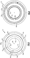
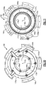
- first 172a and second 172b flow passages are not fluidly connected to each other, i.e. the first 172a and second 172b are discrete, separate flow passages.
- Each flow passage 172a, 172b has a fluid inlet 184 ( Figure 9 ) that receives fluid from a supply.
- the fluid inlets 184 are formed within the mounting plate 166.
- the first 172a and second 172b flow passages extend circumferentially around the ring portion 182 to at least partially surround the central axis 176.
- Figures 8-14 show a configuration where both flow passages 172a, 172b extend completely around the central axis 176.
Landscapes
- Engineering & Computer Science (AREA)
- General Engineering & Computer Science (AREA)
- Mechanical Engineering (AREA)
- Chemical & Material Sciences (AREA)
- Combustion & Propulsion (AREA)
- Sealing Using Fluids, Sealing Without Contact, And Removal Of Oil (AREA)
- Retarders (AREA)
- Turbine Rotor Nozzle Sealing (AREA)
Claims (12)
- Verteilerbaugruppe (64) für einen Gasturbinenmotor, umfassend:eine Montageplatte (66) mit einer Montageschnittstelle (68), die zur Befestigung an ein Gehäuse konfiguriert ist,gekennzeichnet dadurch, dass sie ferner folgendes umfasst:eine Strömungsplatte (70), die an die Montageplatte (66) befestigt ist, um mindestens einen Strömungskanal (72) dazwischen bereitzustellen,wobei die Strömungsplatte (70) eine ringförmige Struktur mit einer mittleren Öffnung (80) umfasst, die eine Mittelachse (76) und einen ersten Ringabschnitt (82) definiert, der durch eine erste innere periphere Fläche (82a), die sich umlaufend um die Achse (76) erstreckt, und eine erste äußere periphere Fläche (82b) definiert wird, die im Verhältnis zu der ersten inneren peripheren Fläche (82a) radial nach außen beabstandet ist;wobei die Montageplatte (66) eine ringförmige Struktur mit einer mittleren Öffnung (74), die zu der Mittelachse (76) konzentrisch ist, und einen zweiten Ringabschnitt (78) umfasst, der durch eine zweite innere periphere Fläche (78a), die sich umlaufend um die Achse (76) erstreckt, und eine zweite äußere periphere Fläche (78b) definiert ist, die im Verhältnis zu der zweiten inneren peripheren Fläche (78a) radial nach außen beabstandet ist; undwobei der mindestens eine Strömungskanal mindestens einen ersten Strömungskanal (72a), der neben der ersten und zweiten inneren peripheren Fläche gebildet ist, und einen zweiten Strömungskanal (72b) umfasst, der neben der ersten und zweiten äußeren peripheren Fläche gebildet ist, wobei sich der erste und zweite Strömungskanal (72a,72b) umlaufend um die ersten und zweiten Ringabschnitte erstrecken, um die Mittlachse (76) mindestens teilweise zu umgeben.
- Verteilerbaugruppe (64) nach Anspruch 1, wobei die Montageplatte (66) einen ersten Kanalabschnitt für jeden von dem ersten und zweiten Strömungskanal definiert, und wobei die Strömungsplatte (70) einen verbleibenden Abschnitt für jeden von dem ersten und zweiten Strömungskanal definiert, und wobei der erste Abschnitt und der verbleibende Abschnitt aneinander angeglichen sind, um den mindestens ersten und zweiten Strömungskanal zu bilden.
- Verteilerbaugruppe (64) nach Anspruch 2, wobei die Montageplatte (66) eine erste Endfläche beinhaltet, die konfiguriert ist, um auf das Gehäuse zu zeigen, und eine zweite Endfläche, die auf die Strömungsplatte (70) zeigt, und wobei die Montageplatte (66) eine Vielzahl von Öffnungen (88a, 88b) beinhaltet, die sich von der ersten Endfläche zu der zweiten Endfläche durch die Montageplatte (66) erstreckt.
- Verteilerbaugruppe (64) nach Anspruch 3, wobei jede Öffnung einen erhöhten Nabenabschnitt (90) beinhaltet, der sich nach außen von der zweiten Endfläche erstreckt, wobei sich die erhöhten Nabenabschnitte in den verbleibenden Abschnitt der Strömungsplatte (70) erstrecken.
- Verteilerbaugruppe (64) nach Anspruch 4, wobei eine äußere periphere Fläche der erhöhten Nabenabschnitte (90) gegen eine innere Fläche des verbleibenden Abschnitts der Strömungsplatte (70) mit mindestens einer Dichtung abgedichtet ist.
- Verteilerbaugruppe (64) nach Anspruch 5, wobei mindestens eine Dichtung ein Paar Dichtungen umfasst, die jeden erhöhten Nabenabschnitt kontaktieren, wobei eine erste Dichtung eine radial innere Nabenfläche abdichtet und eine zweite Dichtung eine radial äußere Nabenfläche abdichtet
- Verteilerbaugruppe (64) nach Anspruch 1, wobei der erste und zweite Strömungskanal (72a, 72b) nicht fluidisch miteinander verbunden sind.
- Verteilerbaugruppe (64) nach Anspruch 1, wobei sich der erste und zweite Strömungskanal (72a, 72b) vollständig um die Mittelachse (76) erstrecken.
- Verteilerbaugruppe (64) nach einem der vorhergehenden Ansprüche, wobei die Montageplatte (66) eine erste Vielzahl von Öffnungen (88a), die dem ersten Strömungskanal (72a) zugeordnet ist, und eine zweite Vielzahl von Öffnungen (88b) beinhaltet, die dem zweiten Strömungskanal (72b) zugeordnet ist, und wobei jede Öffnung einen erhöhten Nabenabschnitt (90) mit einer äußeren Fläche (90a) umfasst, die gegen eine innere Strömungskanalfläche der Strömungsplatte (70) abgedichtet ist.
- Verteilerbaugruppe (64) nach Anspruch 9, wobei mindestens eine Öffnung einen Einlass in Fluidkommunikation mit der Strömungsplatte (70) definiert und ein Auslass zur Leitung von Fluid an eine Getriebebaugruppe (60) konfiguriert ist, die innerhalb des Gehäuses angeordnet ist, und wobei der Einlass durch einen ersten Durchmesser und der Auslass durch einen zweiten Durchmesser definiert ist, der sich von dem ersten Durchmesser unterscheidet.
- Verteilerbaugruppe (164) nach einem der vorhergehenden Ansprüche, wobei der erste Strömungskanal (172a) eine erste radial innerste Fläche (172c) und eine zweite radial äußerste Fläche (172d) beinhaltet, und der zweite Strömungskanal (172b) eine zweite radial innerste Fläche (172e) und eine zweite radial äußerste Fläche (172f) beinhaltet, und beinhaltend eine erste Dichtung (198a), die die erste radial innerste Fläche in Eingriff nimmt, eine zweite Dichtung (198b), die die erste radial äußerste Fläche in Eingriff nimmt, eine dritte Dichtung (198c), die die zweite radial innerste Fläche und eine vierte Dichtung (198d), die die zweite radial äußerste Fläche in Eingriff nimmt.
- Gasturbinenmotor (20), umfassend:eine erste Welle (40), die einen Ventilator (42), einen Niederdruckkompressor (44) und eine Niederdruckturbine (46) verbindet;eine zweite Welle (50), die einen Hochdruckkompressor (52) und eine Hochdruckturbine (54) verbindet, wobei die zweite Welle konfiguriert ist, um sich bei einer schnelleren Geschwindigkeit als die erste Welle zu drehen;eine Getriebearchitektur (48), die die erste Welle zum Antrieb des Ventilators verbindet, wobei die Getriebearchitektur eine Getriebebaugruppe (60) beinhaltet, die innerhalb eines Getriebegehäuses (62) umschlossen ist; undeine Verteilerbaugruppe (64) nach einem der vorhergehenden Ansprüche, wobei die Verteilerbaugruppe mindestens einen Fluideinlass, der zum Aufnehmen von Fluid von einer Zufuhr konfiguriert ist, und mindestens einen Fluidauslass zur Leitung des Fluids in das Getriebegehäuse beinhaltet.
Applications Claiming Priority (2)
| Application Number | Priority Date | Filing Date | Title |
|---|---|---|---|
| US13/459,532 US9163717B2 (en) | 2012-04-30 | 2012-04-30 | Multi-piece fluid manifold for gas turbine engine |
| PCT/US2013/038569 WO2014014538A2 (en) | 2012-04-30 | 2013-04-29 | Manifold for gas turbine engine |
Publications (3)
| Publication Number | Publication Date |
|---|---|
| EP2844855A2 EP2844855A2 (de) | 2015-03-11 |
| EP2844855A4 EP2844855A4 (de) | 2016-03-30 |
| EP2844855B1 true EP2844855B1 (de) | 2017-08-23 |
Family
ID=49476122
Family Applications (1)
| Application Number | Title | Priority Date | Filing Date |
|---|---|---|---|
| EP13820257.7A Active EP2844855B1 (de) | 2012-04-30 | 2013-04-29 | Verteiler für gasturbinenmotor |
Country Status (3)
| Country | Link |
|---|---|
| US (1) | US9163717B2 (de) |
| EP (1) | EP2844855B1 (de) |
| WO (1) | WO2014014538A2 (de) |
Cited By (3)
| Publication number | Priority date | Publication date | Assignee | Title |
|---|---|---|---|---|
| EP3696448A1 (de) | 2019-02-14 | 2020-08-19 | Safran Transmission Systems | Schmierung eines satellitenträgers für ein mechanisches reduktionsgetriebe für turbotriebwerk, insbesondere eines luftfahrzeugs |
| EP3696449A1 (de) | 2019-02-14 | 2020-08-19 | Safran Transmission Systems | Schmierung eines satellitenträgers für ein mechanisches reduktionsgetriebe für turbotriebwerk, insbesondere eines luftfahrzeugs |
| US11598407B1 (en) * | 2022-02-16 | 2023-03-07 | Pratt & Whitney Canada Corp. | Epicyclic gear train of aircraft powerplant |
Families Citing this family (7)
| Publication number | Priority date | Publication date | Assignee | Title |
|---|---|---|---|---|
| WO2015002680A2 (en) * | 2013-06-06 | 2015-01-08 | United Technologies Corporation | Manifold for gas turbine |
| EP3099766B1 (de) | 2014-01-30 | 2018-09-26 | UNL Holdings LLC | Sprühkonfigurationen für doppelkammermischvorrichtungen |
| US9689444B2 (en) * | 2014-04-10 | 2017-06-27 | United Technologies Corporation | Damped anti-rotational systems |
| US10619567B2 (en) * | 2016-04-29 | 2020-04-14 | Rolls-Royce Corporation | Reconfigurable lubrication system for multiple powertrain orientations |
| GB201816504D0 (en) | 2018-10-10 | 2018-11-28 | Rolls Royce Plc | Lubrication system |
| FR3088977B1 (fr) * | 2018-11-23 | 2020-11-27 | Safran Trans Systems | Distributeur d’huile de lubrification pour un reducteur mecanique de turbomachine d’aeronef |
| FR3090786B1 (fr) * | 2018-12-21 | 2020-12-04 | Safran Trans Systems | Distributeur d’huile de lubrification pour un reducteur mecanique de turbomachine d’aeronef |
Family Cites Families (48)
| Publication number | Priority date | Publication date | Assignee | Title |
|---|---|---|---|---|
| US1588632A (en) * | 1924-11-14 | 1926-06-15 | William S Sullivan | Rotary gas engine |
| US2180795A (en) * | 1937-10-02 | 1939-11-21 | Niels A Christensen | Packing |
| US2971334A (en) * | 1955-01-04 | 1961-02-14 | Solar Aircraft Co | Gas turbine engine adaptable for multi-purpose use |
| NL7005063A (de) * | 1970-04-08 | 1971-10-12 | ||
| US3908379A (en) * | 1972-11-10 | 1975-09-30 | William Maurice Bar Fitzgerald | Opposed free piston engine having start, stop, and restart control means |
| US4153141A (en) * | 1977-06-20 | 1979-05-08 | General Electric Company | Auxiliary oil supply system |
| US4152032A (en) * | 1977-10-21 | 1979-05-01 | Westinghouse Electric Corp. | Pressure-fed journal bearing |
| US4265334A (en) * | 1978-12-04 | 1981-05-05 | General Electric Company | Apparatus for lubrication of a differential bearing mounted between concentric shafts |
| GB2043799B (en) * | 1979-03-05 | 1983-03-16 | Rolls Royce | Draining oil from bearing |
| US4243156A (en) * | 1979-03-19 | 1981-01-06 | Lobbestael David A | Closure for a beverage receptacle |
| US4553855A (en) * | 1984-10-18 | 1985-11-19 | Elliott Turbomachinery Company, Inc. | Damper and spring shaft support assembly |
| GB2199900B (en) | 1987-01-15 | 1991-06-19 | Rolls Royce Plc | A turbopropeller or turbofan gas turbine engine |
| US4969325A (en) | 1989-01-03 | 1990-11-13 | General Electric Company | Turbofan engine having a counterrotating partially geared fan drive turbine |
| US4916894A (en) | 1989-01-03 | 1990-04-17 | General Electric Company | High bypass turbofan engine having a partially geared fan drive turbine |
| US5018407A (en) * | 1989-10-27 | 1991-05-28 | Scientific-Atlanta, Inc. | Pedestal assembly having a reduced volume in a lubricant filled housing |
| US5119905A (en) | 1991-10-28 | 1992-06-09 | General Motors Corporation | Accessory drive spline lubrication system for a turbine engine reduction gear box |
| US5183342A (en) * | 1991-12-16 | 1993-02-02 | General Electric Company | Lubricated bearing assembly |
| US5398843A (en) * | 1993-12-02 | 1995-03-21 | Letica Corporation | Drink-through lid for disposable cup |
| US6058694A (en) | 1997-11-11 | 2000-05-09 | Alliedsignal Inc. | Gas turbine engine commanded oil flow valve with failsafe |
| US6746152B2 (en) * | 2001-07-27 | 2004-06-08 | Pioneer Motor Bearing Company | Thrust bearing and method for equalizing load |
| US6682222B2 (en) * | 2001-08-22 | 2004-01-27 | General Electric Company | Bi-directional oil scoop for bearing lubrication |
| JP3495730B2 (ja) * | 2002-04-15 | 2004-02-09 | 三菱重工業株式会社 | ガスタービンの燃焼器 |
| US6997618B2 (en) * | 2003-12-29 | 2006-02-14 | United Technologies Corporation | Bearing housing with divided drainage and oil pooling annulus |
| DE102004042739A1 (de) * | 2004-09-03 | 2006-03-09 | Mtu Aero Engines Gmbh | Fan für ein Flugtriebwerk sowie Flugtriebwerk |
| US8267826B2 (en) * | 2005-03-15 | 2012-09-18 | United Technologies Corporation | Uninterruptible oil supply in planetary system |
| US7329048B2 (en) * | 2005-07-19 | 2008-02-12 | Rolls-Royce Corporation | Self contained squeeze film damping system |
| US7475549B2 (en) * | 2005-08-03 | 2009-01-13 | Hamilton Sundstrand Corporation | Thermal management system for a gas turbine engine |
| US7493753B2 (en) | 2005-10-19 | 2009-02-24 | General Electric Company | Gas turbine engine assembly and methods of assembling same |
| JP4773810B2 (ja) * | 2005-11-28 | 2011-09-14 | 三菱重工業株式会社 | ガスタービン |
| US7861533B2 (en) * | 2006-04-21 | 2011-01-04 | Pratt & Whitney Canada Corp | Relighting a turbofan engine |
| US7704178B2 (en) | 2006-07-05 | 2010-04-27 | United Technologies Corporation | Oil baffle for gas turbine fan drive gear system |
| FR2907167B1 (fr) * | 2006-10-13 | 2011-11-18 | Snecma | Arbre d'entrainement de boitier a engrenages de machines auxiliaires d'un turboreacteur; machine auxiliaire supplementaire modulaire |
| US7662059B2 (en) * | 2006-10-18 | 2010-02-16 | United Technologies Corporation | Lubrication of windmilling journal bearings |
| US7748208B2 (en) * | 2006-12-04 | 2010-07-06 | Hamilton Sundstrand Corporation | Compact recirculating lubrication system for a miniature gas turbine engine |
| US20080135336A1 (en) * | 2006-12-11 | 2008-06-12 | Jewess Gordon F | Under race bearing lubrication system for gas turbine engines |
| US8205432B2 (en) * | 2007-10-03 | 2012-06-26 | United Technologies Corporation | Epicyclic gear train for turbo fan engine |
| US8262344B2 (en) * | 2008-04-02 | 2012-09-11 | Hamilton Sundstrand Corporation | Thermal management system for a gas turbine engine |
| US20100084872A1 (en) * | 2008-10-07 | 2010-04-08 | Adi Wind, Llc | Speed increaser |
| US20100096395A1 (en) * | 2008-10-16 | 2010-04-22 | Mint Urban Technologies Limited | Degradable Beverage Container Lid |
| US8307626B2 (en) | 2009-02-26 | 2012-11-13 | United Technologies Corporation | Auxiliary pump system for fan drive gear system |
| US8398517B2 (en) * | 2009-06-10 | 2013-03-19 | United Technologies Corporation | Journal bearing with single unit jumper tube and filter |
| US8246503B2 (en) * | 2009-06-10 | 2012-08-21 | United Technologies Corporation | Epicyclic gear system with improved lubrication system |
| US8176725B2 (en) | 2009-09-09 | 2012-05-15 | United Technologies Corporation | Reversed-flow core for a turbofan with a fan drive gear system |
| US8381878B2 (en) | 2009-11-12 | 2013-02-26 | United Technologies Corporation | Oil capture and bypass system |
| US9046036B2 (en) * | 2011-05-31 | 2015-06-02 | Honeywell International Inc. | Bearing assembly |
| US8893469B2 (en) * | 2011-06-22 | 2014-11-25 | United Technologies Corporation | Oil bypass channel deaerator for a geared turbofan engine |
| US8690721B2 (en) * | 2011-08-02 | 2014-04-08 | United Technologies Corporation | Journal pin oil supply for gear system |
| US20130319006A1 (en) * | 2012-05-31 | 2013-12-05 | Francis Parnin | Direct feed auxiliary oil system for geared turbofan engine |
-
2012
- 2012-04-30 US US13/459,532 patent/US9163717B2/en active Active
-
2013
- 2013-04-29 WO PCT/US2013/038569 patent/WO2014014538A2/en active Application Filing
- 2013-04-29 EP EP13820257.7A patent/EP2844855B1/de active Active
Non-Patent Citations (1)
| Title |
|---|
| None * |
Cited By (4)
| Publication number | Priority date | Publication date | Assignee | Title |
|---|---|---|---|---|
| EP3696448A1 (de) | 2019-02-14 | 2020-08-19 | Safran Transmission Systems | Schmierung eines satellitenträgers für ein mechanisches reduktionsgetriebe für turbotriebwerk, insbesondere eines luftfahrzeugs |
| EP3696449A1 (de) | 2019-02-14 | 2020-08-19 | Safran Transmission Systems | Schmierung eines satellitenträgers für ein mechanisches reduktionsgetriebe für turbotriebwerk, insbesondere eines luftfahrzeugs |
| EP3696449B1 (de) * | 2019-02-14 | 2024-05-22 | Safran Transmission Systems | Schmierung eines satellitenträgers für ein mechanisches reduktionsgetriebe für turbotriebwerk, insbesondere eines luftfahrzeugs |
| US11598407B1 (en) * | 2022-02-16 | 2023-03-07 | Pratt & Whitney Canada Corp. | Epicyclic gear train of aircraft powerplant |
Also Published As
| Publication number | Publication date |
|---|---|
| US9163717B2 (en) | 2015-10-20 |
| EP2844855A4 (de) | 2016-03-30 |
| US20130283756A1 (en) | 2013-10-31 |
| WO2014014538A2 (en) | 2014-01-23 |
| WO2014014538A3 (en) | 2014-03-27 |
| EP2844855A2 (de) | 2015-03-11 |
Similar Documents
| Publication | Publication Date | Title |
|---|---|---|
| EP2844855B1 (de) | Verteiler für gasturbinenmotor | |
| EP3628850B1 (de) | Getriebe für gasturbinenmotoren | |
| US11391172B2 (en) | Piloted retaining plate for a face seal arrangement | |
| EP3543464B1 (de) | Doppelhohlraumleitblech | |
| EP2921672B1 (de) | Ölverlustschutz für ein getriebefansystem | |
| EP3832088B1 (de) | Verteiler für getriebefanmotor | |
| EP2880275B1 (de) | Versorgungssystem des vorderen bauraums für einen getriebefan | |
| EP3019776B1 (de) | Untrennbarer gefertigter schmiermittelverteiler | |
| EP3296519B1 (de) | Strömungswegkomponente für einen gasturbinenmotor mit einer sehnendichtung | |
| EP3085899A1 (de) | Mittelturbinenrahmen mit abgedichtetem torsionskasten für ein gasturbinentriebwerk | |
| EP2971585B1 (de) | Schienendichtung für eine gasturbinenschaufel | |
| EP3084180B1 (de) | Übertragungslager für getriebefan | |
| EP3450692B1 (de) | Dichtungsanordnung für die schnittstelle zwischen brennkammer und leitschaufel | |
| EP3450693B1 (de) | Dichtungsanordnung für die schnittstelle zwischen brennkammer und leitschaufel | |
| EP2937512B1 (de) | Anordnung für ein gasturbinentriebwerk | |
| EP2867501A1 (de) | Turbinenschaufelplattform mit u-kanal-kühllöchern | |
| EP3450686B1 (de) | Turbinenschaufel-cluster mit verbesserter plattformkühlung | |
| EP2905427B1 (de) | Dichtungsanordnung für Gasturbinenmotor | |
| EP2900960B1 (de) | Auf schwerkraft basierendes siphonsystem mit einer axialdichtung | |
| EP2904217B1 (de) | Leitschaufel und zugehöriger gasturbinenmotor | |
| EP3044424B1 (de) | Blindverschluss für gasturbinenmotor | |
| EP3404215B1 (de) | Gasturbinentriebwerk mit dichtungsverdrehsicherung | |
| EP3192974B1 (de) | Gasturbinenmotorkomponente und zugehöriger gasturbinenmotor |
Legal Events
| Date | Code | Title | Description |
|---|---|---|---|
| PUAI | Public reference made under article 153(3) epc to a published international application that has entered the european phase |
Free format text: ORIGINAL CODE: 0009012 |
|
| 17P | Request for examination filed |
Effective date: 20141112 |
|
| AK | Designated contracting states |
Kind code of ref document: A2 Designated state(s): AL AT BE BG CH CY CZ DE DK EE ES FI FR GB GR HR HU IE IS IT LI LT LU LV MC MK MT NL NO PL PT RO RS SE SI SK SM TR |
|
| AX | Request for extension of the european patent |
Extension state: BA ME |
|
| DAX | Request for extension of the european patent (deleted) | ||
| A4 | Supplementary search report drawn up and despatched |
Effective date: 20160229 |
|
| RIC1 | Information provided on ipc code assigned before grant |
Ipc: F02C 7/22 20060101AFI20160223BHEP Ipc: F02C 7/00 20060101ALI20160223BHEP |
|
| RAP1 | Party data changed (applicant data changed or rights of an application transferred) |
Owner name: UNITED TECHNOLOGIES CORPORATION |
|
| GRAP | Despatch of communication of intention to grant a patent |
Free format text: ORIGINAL CODE: EPIDOSNIGR1 |
|
| STAA | Information on the status of an ep patent application or granted ep patent |
Free format text: STATUS: GRANT OF PATENT IS INTENDED |
|
| INTG | Intention to grant announced |
Effective date: 20170310 |
|
| GRAS | Grant fee paid |
Free format text: ORIGINAL CODE: EPIDOSNIGR3 |
|
| GRAA | (expected) grant |
Free format text: ORIGINAL CODE: 0009210 |
|
| STAA | Information on the status of an ep patent application or granted ep patent |
Free format text: STATUS: THE PATENT HAS BEEN GRANTED |
|
| AK | Designated contracting states |
Kind code of ref document: B1 Designated state(s): AL AT BE BG CH CY CZ DE DK EE ES FI FR GB GR HR HU IE IS IT LI LT LU LV MC MK MT NL NO PL PT RO RS SE SI SK SM TR |
|
| REG | Reference to a national code |
Ref country code: GB Ref legal event code: FG4D |
|
| REG | Reference to a national code |
Ref country code: CH Ref legal event code: EP |
|
| REG | Reference to a national code |
Ref country code: AT Ref legal event code: REF Ref document number: 921608 Country of ref document: AT Kind code of ref document: T Effective date: 20170915 |
|
| REG | Reference to a national code |
Ref country code: IE Ref legal event code: FG4D |
|
| REG | Reference to a national code |
Ref country code: DE Ref legal event code: R096 Ref document number: 602013025584 Country of ref document: DE |
|
| REG | Reference to a national code |
Ref country code: NL Ref legal event code: MP Effective date: 20170823 |
|
| REG | Reference to a national code |
Ref country code: LT Ref legal event code: MG4D |
|
| REG | Reference to a national code |
Ref country code: AT Ref legal event code: MK05 Ref document number: 921608 Country of ref document: AT Kind code of ref document: T Effective date: 20170823 |
|
| PG25 | Lapsed in a contracting state [announced via postgrant information from national office to epo] |
Ref country code: LT Free format text: LAPSE BECAUSE OF FAILURE TO SUBMIT A TRANSLATION OF THE DESCRIPTION OR TO PAY THE FEE WITHIN THE PRESCRIBED TIME-LIMIT Effective date: 20170823 Ref country code: HR Free format text: LAPSE BECAUSE OF FAILURE TO SUBMIT A TRANSLATION OF THE DESCRIPTION OR TO PAY THE FEE WITHIN THE PRESCRIBED TIME-LIMIT Effective date: 20170823 Ref country code: FI Free format text: LAPSE BECAUSE OF FAILURE TO SUBMIT A TRANSLATION OF THE DESCRIPTION OR TO PAY THE FEE WITHIN THE PRESCRIBED TIME-LIMIT Effective date: 20170823 Ref country code: NO Free format text: LAPSE BECAUSE OF FAILURE TO SUBMIT A TRANSLATION OF THE DESCRIPTION OR TO PAY THE FEE WITHIN THE PRESCRIBED TIME-LIMIT Effective date: 20171123 Ref country code: SE Free format text: LAPSE BECAUSE OF FAILURE TO SUBMIT A TRANSLATION OF THE DESCRIPTION OR TO PAY THE FEE WITHIN THE PRESCRIBED TIME-LIMIT Effective date: 20170823 Ref country code: NL Free format text: LAPSE BECAUSE OF FAILURE TO SUBMIT A TRANSLATION OF THE DESCRIPTION OR TO PAY THE FEE WITHIN THE PRESCRIBED TIME-LIMIT Effective date: 20170823 Ref country code: AT Free format text: LAPSE BECAUSE OF FAILURE TO SUBMIT A TRANSLATION OF THE DESCRIPTION OR TO PAY THE FEE WITHIN THE PRESCRIBED TIME-LIMIT Effective date: 20170823 |
|
| PG25 | Lapsed in a contracting state [announced via postgrant information from national office to epo] |
Ref country code: LV Free format text: LAPSE BECAUSE OF FAILURE TO SUBMIT A TRANSLATION OF THE DESCRIPTION OR TO PAY THE FEE WITHIN THE PRESCRIBED TIME-LIMIT Effective date: 20170823 Ref country code: PL Free format text: LAPSE BECAUSE OF FAILURE TO SUBMIT A TRANSLATION OF THE DESCRIPTION OR TO PAY THE FEE WITHIN THE PRESCRIBED TIME-LIMIT Effective date: 20170823 Ref country code: GR Free format text: LAPSE BECAUSE OF FAILURE TO SUBMIT A TRANSLATION OF THE DESCRIPTION OR TO PAY THE FEE WITHIN THE PRESCRIBED TIME-LIMIT Effective date: 20171124 Ref country code: IS Free format text: LAPSE BECAUSE OF FAILURE TO SUBMIT A TRANSLATION OF THE DESCRIPTION OR TO PAY THE FEE WITHIN THE PRESCRIBED TIME-LIMIT Effective date: 20171223 Ref country code: BG Free format text: LAPSE BECAUSE OF FAILURE TO SUBMIT A TRANSLATION OF THE DESCRIPTION OR TO PAY THE FEE WITHIN THE PRESCRIBED TIME-LIMIT Effective date: 20171123 Ref country code: ES Free format text: LAPSE BECAUSE OF FAILURE TO SUBMIT A TRANSLATION OF THE DESCRIPTION OR TO PAY THE FEE WITHIN THE PRESCRIBED TIME-LIMIT Effective date: 20170823 Ref country code: RS Free format text: LAPSE BECAUSE OF FAILURE TO SUBMIT A TRANSLATION OF THE DESCRIPTION OR TO PAY THE FEE WITHIN THE PRESCRIBED TIME-LIMIT Effective date: 20170823 |
|
| REG | Reference to a national code |
Ref country code: FR Ref legal event code: PLFP Year of fee payment: 6 |
|
| PG25 | Lapsed in a contracting state [announced via postgrant information from national office to epo] |
Ref country code: CZ Free format text: LAPSE BECAUSE OF FAILURE TO SUBMIT A TRANSLATION OF THE DESCRIPTION OR TO PAY THE FEE WITHIN THE PRESCRIBED TIME-LIMIT Effective date: 20170823 Ref country code: RO Free format text: LAPSE BECAUSE OF FAILURE TO SUBMIT A TRANSLATION OF THE DESCRIPTION OR TO PAY THE FEE WITHIN THE PRESCRIBED TIME-LIMIT Effective date: 20170823 Ref country code: DK Free format text: LAPSE BECAUSE OF FAILURE TO SUBMIT A TRANSLATION OF THE DESCRIPTION OR TO PAY THE FEE WITHIN THE PRESCRIBED TIME-LIMIT Effective date: 20170823 |
|
| REG | Reference to a national code |
Ref country code: DE Ref legal event code: R097 Ref document number: 602013025584 Country of ref document: DE |
|
| PG25 | Lapsed in a contracting state [announced via postgrant information from national office to epo] |
Ref country code: SK Free format text: LAPSE BECAUSE OF FAILURE TO SUBMIT A TRANSLATION OF THE DESCRIPTION OR TO PAY THE FEE WITHIN THE PRESCRIBED TIME-LIMIT Effective date: 20170823 Ref country code: SM Free format text: LAPSE BECAUSE OF FAILURE TO SUBMIT A TRANSLATION OF THE DESCRIPTION OR TO PAY THE FEE WITHIN THE PRESCRIBED TIME-LIMIT Effective date: 20170823 Ref country code: EE Free format text: LAPSE BECAUSE OF FAILURE TO SUBMIT A TRANSLATION OF THE DESCRIPTION OR TO PAY THE FEE WITHIN THE PRESCRIBED TIME-LIMIT Effective date: 20170823 |
|
| PLBE | No opposition filed within time limit |
Free format text: ORIGINAL CODE: 0009261 |
|
| STAA | Information on the status of an ep patent application or granted ep patent |
Free format text: STATUS: NO OPPOSITION FILED WITHIN TIME LIMIT |
|
| 26N | No opposition filed |
Effective date: 20180524 |
|
| PG25 | Lapsed in a contracting state [announced via postgrant information from national office to epo] |
Ref country code: SI Free format text: LAPSE BECAUSE OF FAILURE TO SUBMIT A TRANSLATION OF THE DESCRIPTION OR TO PAY THE FEE WITHIN THE PRESCRIBED TIME-LIMIT Effective date: 20170823 |
|
| PG25 | Lapsed in a contracting state [announced via postgrant information from national office to epo] |
Ref country code: MC Free format text: LAPSE BECAUSE OF FAILURE TO SUBMIT A TRANSLATION OF THE DESCRIPTION OR TO PAY THE FEE WITHIN THE PRESCRIBED TIME-LIMIT Effective date: 20170823 |
|
| REG | Reference to a national code |
Ref country code: CH Ref legal event code: PL |
|
| REG | Reference to a national code |
Ref country code: BE Ref legal event code: MM Effective date: 20180430 |
|
| REG | Reference to a national code |
Ref country code: IE Ref legal event code: MM4A |
|
| PG25 | Lapsed in a contracting state [announced via postgrant information from national office to epo] |
Ref country code: LU Free format text: LAPSE BECAUSE OF NON-PAYMENT OF DUE FEES Effective date: 20180429 |
|
| PG25 | Lapsed in a contracting state [announced via postgrant information from national office to epo] |
Ref country code: BE Free format text: LAPSE BECAUSE OF NON-PAYMENT OF DUE FEES Effective date: 20180430 Ref country code: LI Free format text: LAPSE BECAUSE OF NON-PAYMENT OF DUE FEES Effective date: 20180430 Ref country code: CH Free format text: LAPSE BECAUSE OF NON-PAYMENT OF DUE FEES Effective date: 20180430 |
|
| PG25 | Lapsed in a contracting state [announced via postgrant information from national office to epo] |
Ref country code: IE Free format text: LAPSE BECAUSE OF NON-PAYMENT OF DUE FEES Effective date: 20180429 |
|
| PG25 | Lapsed in a contracting state [announced via postgrant information from national office to epo] |
Ref country code: MT Free format text: LAPSE BECAUSE OF NON-PAYMENT OF DUE FEES Effective date: 20180429 |
|
| PG25 | Lapsed in a contracting state [announced via postgrant information from national office to epo] |
Ref country code: TR Free format text: LAPSE BECAUSE OF FAILURE TO SUBMIT A TRANSLATION OF THE DESCRIPTION OR TO PAY THE FEE WITHIN THE PRESCRIBED TIME-LIMIT Effective date: 20170823 |
|
| PG25 | Lapsed in a contracting state [announced via postgrant information from national office to epo] |
Ref country code: PT Free format text: LAPSE BECAUSE OF FAILURE TO SUBMIT A TRANSLATION OF THE DESCRIPTION OR TO PAY THE FEE WITHIN THE PRESCRIBED TIME-LIMIT Effective date: 20170823 Ref country code: HU Free format text: LAPSE BECAUSE OF FAILURE TO SUBMIT A TRANSLATION OF THE DESCRIPTION OR TO PAY THE FEE WITHIN THE PRESCRIBED TIME-LIMIT; INVALID AB INITIO Effective date: 20130429 |
|
| PG25 | Lapsed in a contracting state [announced via postgrant information from national office to epo] |
Ref country code: CY Free format text: LAPSE BECAUSE OF FAILURE TO SUBMIT A TRANSLATION OF THE DESCRIPTION OR TO PAY THE FEE WITHIN THE PRESCRIBED TIME-LIMIT Effective date: 20170823 Ref country code: MK Free format text: LAPSE BECAUSE OF NON-PAYMENT OF DUE FEES Effective date: 20170823 |
|
| PG25 | Lapsed in a contracting state [announced via postgrant information from national office to epo] |
Ref country code: AL Free format text: LAPSE BECAUSE OF FAILURE TO SUBMIT A TRANSLATION OF THE DESCRIPTION OR TO PAY THE FEE WITHIN THE PRESCRIBED TIME-LIMIT Effective date: 20170823 |
|
| REG | Reference to a national code |
Ref country code: DE Ref legal event code: R081 Ref document number: 602013025584 Country of ref document: DE Owner name: RAYTHEON TECHNOLOGIES CORPORATION (N.D.GES.D.S, US Free format text: FORMER OWNER: UNITED TECHNOLOGIES CORPORATION, FARMINGTON, CONN., US |
|
| P01 | Opt-out of the competence of the unified patent court (upc) registered |
Effective date: 20230520 |
|
| PGFP | Annual fee paid to national office [announced via postgrant information from national office to epo] |
Ref country code: GB Payment date: 20240320 Year of fee payment: 12 |
|
| PGFP | Annual fee paid to national office [announced via postgrant information from national office to epo] |
Ref country code: IT Payment date: 20240320 Year of fee payment: 12 Ref country code: FR Payment date: 20240320 Year of fee payment: 12 |
|
| PGFP | Annual fee paid to national office [announced via postgrant information from national office to epo] |
Ref country code: DE Payment date: 20240320 Year of fee payment: 12 |