EP2844492B1 - Web inkjet printing method and apparatus using an air bar - Google Patents
Web inkjet printing method and apparatus using an air bar Download PDFInfo
- Publication number
- EP2844492B1 EP2844492B1 EP13785264.6A EP13785264A EP2844492B1 EP 2844492 B1 EP2844492 B1 EP 2844492B1 EP 13785264 A EP13785264 A EP 13785264A EP 2844492 B1 EP2844492 B1 EP 2844492B1
- Authority
- EP
- European Patent Office
- Prior art keywords
- web
- air
- air bar
- zone
- bar
- Prior art date
- Legal status (The legal status is an assumption and is not a legal conclusion. Google has not performed a legal analysis and makes no representation as to the accuracy of the status listed.)
- Active
Links
- 238000000034 method Methods 0.000 title claims description 16
- 238000007641 inkjet printing Methods 0.000 title claims description 14
- 238000007639 printing Methods 0.000 claims description 31
- 238000001035 drying Methods 0.000 claims description 23
- 230000007246 mechanism Effects 0.000 claims 2
- 230000007723 transport mechanism Effects 0.000 claims 1
- 239000000976 ink Substances 0.000 description 24
- 239000000463 material Substances 0.000 description 5
- 238000010438 heat treatment Methods 0.000 description 4
- 239000000758 substrate Substances 0.000 description 4
- 230000008859 change Effects 0.000 description 2
- 230000000694 effects Effects 0.000 description 2
- 238000012546 transfer Methods 0.000 description 2
- OKTJSMMVPCPJKN-UHFFFAOYSA-N Carbon Chemical compound [C] OKTJSMMVPCPJKN-UHFFFAOYSA-N 0.000 description 1
- 230000009471 action Effects 0.000 description 1
- 230000015572 biosynthetic process Effects 0.000 description 1
- 238000007664 blowing Methods 0.000 description 1
- 229910052799 carbon Inorganic materials 0.000 description 1
- 230000015556 catabolic process Effects 0.000 description 1
- 238000006243 chemical reaction Methods 0.000 description 1
- 239000002131 composite material Substances 0.000 description 1
- 230000003750 conditioning effect Effects 0.000 description 1
- 238000006731 degradation reaction Methods 0.000 description 1
- 230000018044 dehydration Effects 0.000 description 1
- 238000006297 dehydration reaction Methods 0.000 description 1
- 238000013461 design Methods 0.000 description 1
- 230000006866 deterioration Effects 0.000 description 1
- 230000005684 electric field Effects 0.000 description 1
- 230000005484 gravity Effects 0.000 description 1
- 238000001459 lithography Methods 0.000 description 1
- 238000004519 manufacturing process Methods 0.000 description 1
- 239000011159 matrix material Substances 0.000 description 1
- 229910052751 metal Inorganic materials 0.000 description 1
- 239000002184 metal Substances 0.000 description 1
- 230000004048 modification Effects 0.000 description 1
- 238000012986 modification Methods 0.000 description 1
- 230000008569 process Effects 0.000 description 1
- 238000012545 processing Methods 0.000 description 1
- 238000011160 research Methods 0.000 description 1
- 230000007480 spreading Effects 0.000 description 1
- 239000000126 substance Substances 0.000 description 1
- WFKWXMTUELFFGS-UHFFFAOYSA-N tungsten Chemical compound [W] WFKWXMTUELFFGS-UHFFFAOYSA-N 0.000 description 1
- 229910052721 tungsten Inorganic materials 0.000 description 1
- 239000010937 tungsten Substances 0.000 description 1
- XLYOFNOQVPJJNP-UHFFFAOYSA-N water Substances O XLYOFNOQVPJJNP-UHFFFAOYSA-N 0.000 description 1
Images
Classifications
-
- B—PERFORMING OPERATIONS; TRANSPORTING
- B41—PRINTING; LINING MACHINES; TYPEWRITERS; STAMPS
- B41J—TYPEWRITERS; SELECTIVE PRINTING MECHANISMS, i.e. MECHANISMS PRINTING OTHERWISE THAN FROM A FORME; CORRECTION OF TYPOGRAPHICAL ERRORS
- B41J11/00—Devices or arrangements of selective printing mechanisms, e.g. ink-jet printers or thermal printers, for supporting or handling copy material in sheet or web form
- B41J11/0015—Devices or arrangements of selective printing mechanisms, e.g. ink-jet printers or thermal printers, for supporting or handling copy material in sheet or web form for treating before, during or after printing or for uniform coating or laminating the copy material before or after printing
- B41J11/002—Curing or drying the ink on the copy materials, e.g. by heating or irradiating
-
- B—PERFORMING OPERATIONS; TRANSPORTING
- B41—PRINTING; LINING MACHINES; TYPEWRITERS; STAMPS
- B41J—TYPEWRITERS; SELECTIVE PRINTING MECHANISMS, i.e. MECHANISMS PRINTING OTHERWISE THAN FROM A FORME; CORRECTION OF TYPOGRAPHICAL ERRORS
- B41J11/00—Devices or arrangements of selective printing mechanisms, e.g. ink-jet printers or thermal printers, for supporting or handling copy material in sheet or web form
- B41J11/0015—Devices or arrangements of selective printing mechanisms, e.g. ink-jet printers or thermal printers, for supporting or handling copy material in sheet or web form for treating before, during or after printing or for uniform coating or laminating the copy material before or after printing
-
- B—PERFORMING OPERATIONS; TRANSPORTING
- B41—PRINTING; LINING MACHINES; TYPEWRITERS; STAMPS
- B41J—TYPEWRITERS; SELECTIVE PRINTING MECHANISMS, i.e. MECHANISMS PRINTING OTHERWISE THAN FROM A FORME; CORRECTION OF TYPOGRAPHICAL ERRORS
- B41J11/00—Devices or arrangements of selective printing mechanisms, e.g. ink-jet printers or thermal printers, for supporting or handling copy material in sheet or web form
- B41J11/0015—Devices or arrangements of selective printing mechanisms, e.g. ink-jet printers or thermal printers, for supporting or handling copy material in sheet or web form for treating before, during or after printing or for uniform coating or laminating the copy material before or after printing
- B41J11/002—Curing or drying the ink on the copy materials, e.g. by heating or irradiating
- B41J11/0022—Curing or drying the ink on the copy materials, e.g. by heating or irradiating using convection means, e.g. by using a fan for blowing or sucking air
-
- B—PERFORMING OPERATIONS; TRANSPORTING
- B41—PRINTING; LINING MACHINES; TYPEWRITERS; STAMPS
- B41J—TYPEWRITERS; SELECTIVE PRINTING MECHANISMS, i.e. MECHANISMS PRINTING OTHERWISE THAN FROM A FORME; CORRECTION OF TYPOGRAPHICAL ERRORS
- B41J15/00—Devices or arrangements of selective printing mechanisms, e.g. ink-jet printers or thermal printers, specially adapted for supporting or handling copy material in continuous form, e.g. webs
- B41J15/04—Supporting, feeding, or guiding devices; Mountings for web rolls or spindles
-
- B—PERFORMING OPERATIONS; TRANSPORTING
- B41—PRINTING; LINING MACHINES; TYPEWRITERS; STAMPS
- B41J—TYPEWRITERS; SELECTIVE PRINTING MECHANISMS, i.e. MECHANISMS PRINTING OTHERWISE THAN FROM A FORME; CORRECTION OF TYPOGRAPHICAL ERRORS
- B41J3/00—Typewriters or selective printing or marking mechanisms characterised by the purpose for which they are constructed
- B41J3/60—Typewriters or selective printing or marking mechanisms characterised by the purpose for which they are constructed for printing on both faces of the printing material
Definitions
- This invention relates to duplex inkjet printing onto a web of paper or like medium.
- Such stations may include stations for preparing the surface of the paper with ink or some impregnating material to condition the paper for subsequent operations or to finish the paper for commercial sale and use. It is known to direct such a web along a path using rollers which may be drive rollers used to drive the web or idler rollers which may change the direction of the web. Rollers are contact elements and consequently, a web of paper or like material as it passes over a driven or idler roller will experience some pressure where it contacts the roller surface.
- a printed surface which will contact a roller in the course of paper feed is first dried by passing the web through a radiant heating station where the web passes between two banks of heat lamps.
- the lamps of the two banks are arranged vertically with the web being redirected upwardly from a horizontal printing orientation to a vertical drying orientation.
- the dryer fuser is preferably housed in a cabinet which is spaced from the printing zone in order that the dryer heat does not reach the printheads which might otherwise cause dehydration of the ink exposed at the printhead nozzles.
- EP2082885A1 describes a continuous paper web duplex inkjet printing unit for inkjet printing on both sides of a continuous paper web.
- WO2011/076677A1 describes a turning unit for sheet-like substrates with at least one first turning element with a basic body having an outer round substrate contact surface for deflecting the substrate.
- JPH0753102A describes a method for carrying out the conversion and drying of a traveling web without generating any dirt on a printed matter by suspending a sintered metal roller bar provided with multiple micro holes in the perpendicular direction to the traveling web and blowing out heated air from the micro holes.
- duplex inkjet printing apparatus according to claim 1.
- the web is transported in a transport direction past successive printing stations.
- One side of the web is printed at a first of the stations and the web is passed through a dryer to dry the applied ink and the underlying paper substrate and then a cooler to cool the web and to make its reverse surface receptive for printing.
- the dried, cooled web is then printed at the second of the printing stations.
- the one surface of the web is printed from above while the reverse surface of the web is printed from below.
- Such an arrangement is not effective for ink jet printing.
- FIG. 1 there is illustrated inkjet printing apparatus for duplex printing on a paper web 10 according to an embodiment of the invention.
- the paper web 10 is driven along a transport path by a combination of a drive roller 12 and idler rollers 14.
- One surface 16 of the web is printed at a printing station 18 and the other surface 20 of the web is printed at a printing station 22.
- Each of the printed images may be a composite image obtained by having multiple printheads in tandem so that the printheads at each station each print a partial image which is in accurate registration with the partial images printed by the other tandem-mounted printheads.
- Such combination image printing is done for any of a number of reasons including achieving high web processing speeds, printing an image on a sheet with a large number of inks, and printing characters with a greater ink thickness, and therefore colour density or magnetic ink character recognition (MICR) signal strength, than can be achieved with a single print head.
- the term "ink” is used to cover inks of different colour, primer materials for conditioning the paper to obtain quality print effects, water, and any other jettable substance that can contribute to the formation of an image on the paper web.
- inkjet printer heads operate by ejecting droplets of ink onto the paper web.
- Such printers have print heads that are non-contact heads with ink being transferred during the printing process as minute "flying" ink droplets over a short distance of the order of 1 ⁇ 2 to 1 millimetre.
- Modern inkjet printers are generally of the continuous type or the drop-on-demand type. In the continuous type, ink is pumped along conduits from ink reservoirs to nozzles. The ink is subjected to vibration to break the ink stream into droplets, with the droplets being charged so that they can be controllably deflected in an applied electric field.
- inkjet print heads Commercially available from Silverbrook Research, these being sold under the MEMJET ® tradename which have a very high nozzle density, page wide array and of the order of five channels per print head. Such inkjet print heads have a high resolution of the order of 1600 dots per inch.
- printheads 24, 26 at both the printing stations 18, 22 are oriented to print downwardly as shown in FIG. 1 .
- the print stations 18, 22 are stacked generally vertically.
- an S-form transport path is adopted with the print station sites occupying two of the horizontal spans of the S-form and with the web being turned between adjacent spans.
- the printing stations 18, 22 occupy the upper two horizontal spans of the S-form path but the stations could occupy the two lower spans in a different configuration according to an embodiment of the invention.
- While functional turning of the web 10 can be achieved with conventional rollers, there is a risk of an image being damaged if the printed image contacts an idler roller surface downstream of a printing station.
- the image may be damaged by smudging if there is even a minute movement of the web relative to the idler roller surface.
- the image may be damaged by localized transfer of ink from the paper to the roller with associated problems of leaving detritus on the roller which may affect the quality of images on a downstream length of the web.
- the web 10 is turned through substantially 180 degrees by means of two conventional rollers 30 to bring the web surface 20 under the printing station 22 to complete the duplex printing of the web.
- air bar 28 is used so that the printed image on the surface 16 of the web, which may still be wet, is separated from any hard surface as the web rounds the 180 turn.
- Suitable air bars are available commercially from DMS, Inc., 570a Telser Road, Lake Zurich, IL 60047, USA. The design and operation of an exemplary air bar is described and illustrated in U.S. Patent 6,364,247 .
- air bars can be used at these turn sites if desired for other reasons.
- the or each air bar 28 is operated so as to generate a cushion of air 32 over an appropriately configured arc between the inside surface of the web 10 and an air emission surface 34 of the air bar so that the image printed on the surface 16 of the web is not damaged by a hard contact at the associated turn.
- the air pressure at the surface of the air bar 28 is selected in relation to the tension in the transported web 10 to maintain an air cushion gap of a desired width.
- the air bar is formed as a hollow cylindrical plenum 36, the plenum having walls 38 that are rendered porous by a matrix of micro-perforations extending through the walls.
- the micro-perforations act to transfer air that is pumped under pressure into the plenum 36 so that air expelled from the micro-perforations form the air cushion to maintain the moving web 10 in spaced relationship from the air bar surface 34.
- the rate of escape of air around side edges of the web 10 is limited. This, in turn, limits the generation of air currents which are undesirable as they could cause deflection of flying droplets as they are transferred from the print heads 24, 26 to the paper surfaces.
- the air bar has an arc of porosity which depends on the angle of turn of the web.
- the air bar 28 there is a turn of 180 degrees at the air bar 28 and a further turn of 90 degrees at an air bar 40 to lead the web 10 from an output zone 42 to a drying unit 44.
- the porous regions within the walls of the air bars 28 and 40 are on the order of 180 degrees and 90 degrees respectively to match the turn angles.
- the porosity of plenum wall 38 at the arcuate active region varies from a central region 46 towards flanking outer regions 48. The variation is shown as a sudden variation but can be a phased variation.
- the porosity profile is such as to encourage a lower air flow at the central region 46 compared with the flanking regions 48 so as to maintain a desired turn profile in the web 10 as it is turned at the air bar 28.
- a tension in the paper web 10 in the order of 0.88 to 1.75 N/cm (0.5 to 1 pound per inch) of paper width was maintained, resulting in 44.5 to 89 N (10 to 20 pounds) of tension in a 0.51 m (20 inch) wide web.
- the air pressure within the air bars 28, 40 was measured at about 1379-1724 hPa (20-25 psi) with air consumption for 0.51 m (20 inch) wide being about 0.1 cubic meter per minute (3.6 cubic feet per minute).
- the drying unit / fuser 44 is mounted so that the paper web 10 is driven vertically through the drying zone.
- the drying unit 44 has two banks of heat lamps such as tungsten filament lamps to emit short wavelengths and carbon filament lamps to emit longer wavelengths.
- the lamps radiate heat at the respective surfaces of the web 10 as the web passes between the two banks.
- the heating elements and optional reflectors are rated and positioned so as to achieve distributed drying / fusing action over the area of the printed image but without causing high intensity heating of the paper and printed ink which might otherwise cause deterioration of the image or damage to the paper. If the web has to be stopped temporarily, the heat lamps are switched off or redirected to protect the paper and the images.
- drying unit / fuser from the heat lamp arrangements illustrated are envisaged for use in the context of other embodiments of the invention.
- the air bar (or air bars if used at more than one turn) can use heated and or dried air to provide preliminary drying of the associated surface of the web.
Landscapes
- Ink Jet (AREA)
Description
- The present application claims priority under 35 USC 119(e) to the provisionally filed U.S. Application entitled, WEB INKJET PRINTING METHOD AND APPARATUS USING AN AIR BAR, having serial no.
61/642291, and filed on May 3, 2012 - This invention relates to duplex inkjet printing onto a web of paper or like medium.
- Systems for driving a continuous web of paper or like material past various stations are known. Such stations may include stations for preparing the surface of the paper with ink or some impregnating material to condition the paper for subsequent operations or to finish the paper for commercial sale and use. It is known to direct such a web along a path using rollers which may be drive rollers used to drive the web or idler rollers which may change the direction of the web. Rollers are contact elements and consequently, a web of paper or like material as it passes over a driven or idler roller will experience some pressure where it contacts the roller surface. To prevent degradation of print quality by smudging or spreading of the ink, a printed surface which will contact a roller in the course of paper feed is first dried by passing the web through a radiant heating station where the web passes between two banks of heat lamps. Typically, the lamps of the two banks are arranged vertically with the web being redirected upwardly from a horizontal printing orientation to a vertical drying orientation. The dryer fuser is preferably housed in a cabinet which is spaced from the printing zone in order that the dryer heat does not reach the printheads which might otherwise cause dehydration of the ink exposed at the printhead nozzles.
-
EP2082885A1 describes a continuous paper web duplex inkjet printing unit for inkjet printing on both sides of a continuous paper web.WO2011/076677A1 describes a turning unit for sheet-like substrates with at least one first turning element with a basic body having an outer round substrate contact surface for deflecting the substrate.JPH0753102A - According to one aspect of the invention, there is provided duplex inkjet printing apparatus according to claim 1.
- According to another aspect of the invention, there is provided a method for duplex inkjet printing according to claim 7.
- For simplicity and clarity of illustration, elements illustrated in the following figures are not drawn to common scale. For example, the dimensions of some of the elements are exaggerated relative to other elements for clarity. Advantages, features and characteristics of the present invention, as well as methods, operation and functions of related elements of structure, and the combinations of parts and economies of manufacture, will become apparent upon consideration of the following description and claims with reference to the accompanying drawings, all of which form a part of the specification, wherein like reference numerals designate corresponding parts in the various figures, and wherein:
-
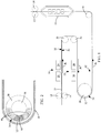
FIG. 1 is a side view of a duplex inkjet printing apparatus according to an embodiment of the invention. -
FIG. 2 is a sectional view of one form of air bar for effecting a web turn in the apparatus ofFIG. 1 - In known arrangements for printing of both sides of a web using, for example, a technique such as offset web lithography, the web is transported in a transport direction past successive printing stations. One side of the web is printed at a first of the stations and the web is passed through a dryer to dry the applied ink and the underlying paper substrate and then a cooler to cool the web and to make its reverse surface receptive for printing. The dried, cooled web is then printed at the second of the printing stations. For speed and ease of handling, the one surface of the web is printed from above while the reverse surface of the web is printed from below. Such an arrangement is not effective for ink jet printing. This sort of arrangement of cannot be used in inkjet printing because ink droplets from an inkjet print head can only really be accurately applied if ink from the print head is directed downwardly so that the droplets are subjected to a combination of an ejection pressure to eject them from the print head nozzles coupled with the application of gravity as the droplets "fly" from the nozzles to the paper web.
- Referring in detail to
FIG. 1 , there is illustrated inkjet printing apparatus for duplex printing on apaper web 10 according to an embodiment of the invention. Thepaper web 10 is driven along a transport path by a combination of adrive roller 12 andidler rollers 14. Onesurface 16 of the web is printed at aprinting station 18 and theother surface 20 of the web is printed at aprinting station 22. Each of the printed images may be a composite image obtained by having multiple printheads in tandem so that the printheads at each station each print a partial image which is in accurate registration with the partial images printed by the other tandem-mounted printheads. Such combination image printing is done for any of a number of reasons including achieving high web processing speeds, printing an image on a sheet with a large number of inks, and printing characters with a greater ink thickness, and therefore colour density or magnetic ink character recognition (MICR) signal strength, than can be achieved with a single print head. In this respect, the term "ink" is used to cover inks of different colour, primer materials for conditioning the paper to obtain quality print effects, water, and any other jettable substance that can contribute to the formation of an image on the paper web. - As is well-known, inkjet printer heads operate by ejecting droplets of ink onto the paper web. Such printers have print heads that are non-contact heads with ink being transferred during the printing process as minute "flying" ink droplets over a short distance of the order of ½ to 1 millimetre. Modern inkjet printers are generally of the continuous type or the drop-on-demand type. In the continuous type, ink is pumped along conduits from ink reservoirs to nozzles. The ink is subjected to vibration to break the ink stream into droplets, with the droplets being charged so that they can be controllably deflected in an applied electric field. In a thermal drop-on-demand type, the ink is subjected to rapid heating of a small volume of ink to form a vapour bubble which expels a corresponding droplet of ink. In piezoelectric drop-on-demand printers, a voltage is applied to change the shape of a piezoelectric material and so generate a pressure pulse in the ink and force a droplet from the nozzle. Of particular interest in the context of the present invention are inkjet print heads commercially available from Silverbrook Research, these being sold under the MEMJET ® tradename which have a very high nozzle density, page wide array and of the order of five channels per print head. Such inkjet print heads have a high resolution of the order of 1600 dots per inch.
- Unlike other printing techniques, an adequate image can only really be achieved by inkjet printing if the printheads print downwardly. Consequently,
printheads printing stations FIG. 1 . To accommodate the twoprinting stations print stations FIG. 1 , theprinting stations - While functional turning of the
web 10 can be achieved with conventional rollers, there is a risk of an image being damaged if the printed image contacts an idler roller surface downstream of a printing station. The image may be damaged by smudging if there is even a minute movement of the web relative to the idler roller surface. Or the image may be damaged by localized transfer of ink from the paper to the roller with associated problems of leaving detritus on the roller which may affect the quality of images on a downstream length of the web. - As illustrated in
FIG. 1 , following printing of theweb surface 16 at theprinting station 18, theweb 10 is turned through substantially 180 degrees by means of twoconventional rollers 30 to bring theweb surface 20 under theprinting station 22 to complete the duplex printing of the web. To effect a further 180 degree turn,air bar 28 is used so that the printed image on thesurface 16 of the web, which may still be wet, is separated from any hard surface as the web rounds the 180 turn. Suitable air bars are available commercially from DMS, Inc., 570a Telser Road, Lake Zurich, IL 60047, USA. The design and operation of an exemplary air bar is described and illustrated inU.S. Patent 6,364,247 . While the other turns in the S-form transport path are effected usingconventional rollers 30 in the illustrated embodiment, air bars can be used at these turn sites if desired for other reasons. The or eachair bar 28 is operated so as to generate a cushion ofair 32 over an appropriately configured arc between the inside surface of theweb 10 and anair emission surface 34 of the air bar so that the image printed on thesurface 16 of the web is not damaged by a hard contact at the associated turn. The air pressure at the surface of theair bar 28 is selected in relation to the tension in the transportedweb 10 to maintain an air cushion gap of a desired width. - In an embodiment of the invention, the air bar is formed as a hollow
cylindrical plenum 36, theplenum having walls 38 that are rendered porous by a matrix of micro-perforations extending through the walls. The micro-perforations act to transfer air that is pumped under pressure into theplenum 36 so that air expelled from the micro-perforations form the air cushion to maintain the movingweb 10 in spaced relationship from theair bar surface 34. By using micro-perforations, the rate of escape of air around side edges of theweb 10 is limited. This, in turn, limits the generation of air currents which are undesirable as they could cause deflection of flying droplets as they are transferred from the print heads 24, 26 to the paper surfaces. The air bar has an arc of porosity which depends on the angle of turn of the web. In the illustrated embodiment, there is a turn of 180 degrees at theair bar 28 and a further turn of 90 degrees at anair bar 40 to lead theweb 10 from anoutput zone 42 to adrying unit 44. The porous regions within the walls of the air bars 28 and 40 are on the order of 180 degrees and 90 degrees respectively to match the turn angles. In addition, as shown in the sectional view ofFIG. 2 , the porosity ofplenum wall 38 at the arcuate active region varies from acentral region 46 towards flankingouter regions 48. The variation is shown as a sudden variation but can be a phased variation. The porosity profile is such as to encourage a lower air flow at thecentral region 46 compared with the flankingregions 48 so as to maintain a desired turn profile in theweb 10 as it is turned at theair bar 28. In one specific implementation of the above described embodiment, a tension in thepaper web 10 in the order of 0.88 to 1.75 N/cm (0.5 to 1 pound per inch) of paper width was maintained, resulting in 44.5 to 89 N (10 to 20 pounds) of tension in a 0.51 m (20 inch) wide web. The air pressure within the air bars 28, 40 was measured at about 1379-1724 hPa (20-25 psi) with air consumption for 0.51 m (20 inch) wide being about 0.1 cubic meter per minute (3.6 cubic feet per minute). - It will be appreciated that using an air bar to turn paper at a wet image obviates a dryer and cooler that would normally be required immediately downstream of a printing station to stabilize the first printed surface before the reverse surface can be printed. By using the
air bar 28 with the stacked printhead configuration, the first printedsurface 16 can remain wet while thesecond surface 20 is being printed so that only onedownstream drying unit 44 is required. In the embodiment shown inFIG. 1 , after the reverse surface of the web is printed at the inkjet print head array , the web is turned through a 90 degree turn and is driven though the drying unit. - For convenience, the drying unit /
fuser 44 is mounted so that thepaper web 10 is driven vertically through the drying zone. The dryingunit 44 has two banks of heat lamps such as tungsten filament lamps to emit short wavelengths and carbon filament lamps to emit longer wavelengths. The lamps radiate heat at the respective surfaces of theweb 10 as the web passes between the two banks. The heating elements and optional reflectors are rated and positioned so as to achieve distributed drying / fusing action over the area of the printed image but without causing high intensity heating of the paper and printed ink which might otherwise cause deterioration of the image or damage to the paper. If the web has to be stopped temporarily, the heat lamps are switched off or redirected to protect the paper and the images. Alternative forms of drying unit / fuser from the heat lamp arrangements illustrated are envisaged for use in the context of other embodiments of the invention. As an adjunct to the dryer, the air bar (or air bars if used at more than one turn) can use heated and or dried air to provide preliminary drying of the associated surface of the web. - Other variations and modifications will be apparent to those skilled in the art. The embodiments of the invention described and illustrated are not intended to be limiting. The principles of the invention contemplate many alternatives having advantages and properties evident in the exemplary embodiments.
Claims (12)
- Duplex inkjet printing apparatus comprising first (24) and second (26) inkjet printheads for printing on opposite surfaces (16, 20) of a web medium (10), and a transport mechanism for transporting the web along an S-form transport path with generally horizontal top, middle and bottom spans and turns linking adjacent spans, the central span passing by the first printhead (24) for downward printing by the first printhead (24) onto one surface (16) of the web medium (10), one of the top and bottom spans passing by the second printhead (26) for downward printing by the second printhead (26) onto the other surface of the web (20), at least one of the turns defined by an air bar (28), one of the top and bottom spans including a web entry zone, the other of the top and bottom spans including a web exit zone, the apparatus further comprising a single web drying unit (44) located to receive the web (10) for drying from the web exit zone, the web drying unit (44) including radiant drying elements for drying both surfaces (16, 20) of the web (10) as the web passes through the drying unit (44).
- Printing apparatus as claimed in claim 1, wherein the level of the first printhead (24) is below the level of the second printhead (26).
- Printing apparatus as claimed in claim 1, the air bar (28) being a porous structure type air bar.
- Printing apparatus as claimed in claim 1, the air bar (28) having an air jet emission zone, the zone extending around the air bar (28) through an angle substantially equal to the angle through which the web is turned at the air bar (28).
- Printing apparatus as claimed in claim 4, the air jet emission zone having an entry region where the moving web is first turned onto the air bar (28), a central region (46) around which the moving web is driven, and an exit region where the moving web moves away from the air bar (28) after completing the turn, jet emission characteristics at the central region (46) being different from jet emission characteristics at the entry and exit regions.
- Printing apparatus as claimed in claim 1, the web drying unit (44) oriented to receive a web (10) passing generally vertically therethrough, and an air bar turn mechanism between the output zone and the web drying unit to turn the web from a generally horizontal orientation to a generally vertical orientation.
- A method for duplex inkjet printing on a web medium, comprising guiding a web medium (10) along an S-form transport path having generally horizontal top, middle and bottom spans and turns linking adjacent spans, operating a first inkjet printhead (24) to print onto a first surface (16) of the web at the middle span, operating a second inkjet printhead (26) to print onto the opposite surface (20) of the web at one of the top and bottom spans, effecting at least one of the turns by means of an air bar (28) directing air at a printed one of the surfaces, transporting the web along the S-form transport path from an input zone to an output zone, the method further comprising transporting the web from the output zone to a single web drying unit (44).
- A method as claimed in claim 7, wherein the web is transported generally vertically through the web drying unit (44), the method further comprising turning the web around an air bar mechanism from a generally horizontal orientation at the output zone to a generally vertical position for entry into the drying unit (44).
- A method as claimed in claim 7, further comprising using an air bar (28) of the porous type to generate an air cushion (32) without high pressure air jets at the air bar.
- A method as claimed in claim 7, further comprising the air bar (28) emitting air over an arc substantially the same as an arc of turn of the web at the air bar.
- A method as claimed in claim 10, further comprising developing an air cushion (32) at the air bar having an entry region where the moving web is first turned at the air bar (28), a central region (46) around which the moving web is driven, and an exit region where the moving web moves away from the air bar (28) after completing the turn, and developing such air cushion (32) to have a characteristic at the central region (46) that is different from a corresponding characteristic at at least one of the entry and exit regions.
- A method as claimed in claim 7, further comprising the air bar (28) emitting drying air.
Applications Claiming Priority (2)
| Application Number | Priority Date | Filing Date | Title |
|---|---|---|---|
| US201261642291P | 2012-05-03 | 2012-05-03 | |
| PCT/CA2013/000448 WO2013163750A1 (en) | 2012-05-03 | 2013-05-02 | Web inkjet printing method and apparatus using an air bar |
Publications (3)
| Publication Number | Publication Date |
|---|---|
| EP2844492A1 EP2844492A1 (en) | 2015-03-11 |
| EP2844492A4 EP2844492A4 (en) | 2016-10-19 |
| EP2844492B1 true EP2844492B1 (en) | 2019-07-31 |
Family
ID=49512227
Family Applications (1)
| Application Number | Title | Priority Date | Filing Date |
|---|---|---|---|
| EP13785264.6A Active EP2844492B1 (en) | 2012-05-03 | 2013-05-02 | Web inkjet printing method and apparatus using an air bar |
Country Status (3)
| Country | Link |
|---|---|
| US (1) | US8882258B2 (en) |
| EP (1) | EP2844492B1 (en) |
| WO (1) | WO2013163750A1 (en) |
Families Citing this family (9)
| Publication number | Priority date | Publication date | Assignee | Title |
|---|---|---|---|---|
| JP6354475B2 (en) * | 2014-09-09 | 2018-07-11 | 株式会社リコー | Image recording device |
| US9376582B1 (en) | 2015-07-30 | 2016-06-28 | Eastman Kodak Company | Printing on water-impermeable substrates with water-based inks |
| US9573349B1 (en) | 2015-07-30 | 2017-02-21 | Eastman Kodak Company | Multilayered structure with water-impermeable substrate |
| JP6778559B2 (en) * | 2016-09-07 | 2020-11-04 | 株式会社ミマキエンジニアリング | Color developer and printing equipment |
| JP6718390B2 (en) * | 2017-02-01 | 2020-07-08 | 株式会社Screenホールディングス | Printer |
| DE102017107991A1 (en) * | 2017-04-13 | 2018-10-18 | Océ Holding B.V. | Inkjet printing device with optimized guidance of a recording medium |
| NL2021317B1 (en) * | 2018-07-16 | 2020-01-24 | Xeikon Mfg Nv | Apparatus and method for inkjet printing on flexible webs |
| CN113524928A (en) * | 2021-08-12 | 2021-10-22 | 露乐健康科技股份有限公司 | Online printing device for paper diaper and paper product packaging materials |
| CN114654901B (en) * | 2022-03-14 | 2025-08-05 | 上海勋朗机电科技有限公司 | Double-sided printing material collection and unloading structure |
Family Cites Families (25)
| Publication number | Priority date | Publication date | Assignee | Title |
|---|---|---|---|---|
| DE2215532B2 (en) * | 1972-03-30 | 1976-01-02 | Saueressig Gmbh, 4422 Ahaus | Roller printing machine for multi-colored printing of webs |
| US4342413A (en) * | 1981-02-05 | 1982-08-03 | Crown Zellerbach Corporation | Turning bar for moving web |
| DE10235391A1 (en) * | 2002-08-02 | 2004-12-30 | Koenig & Bauer Ag | Device for guiding a web and processing machine with the device |
| US5070628A (en) * | 1990-01-16 | 1991-12-10 | W. R. Grace & Co.-Conn. | Rotatable slot nozzle air bar |
| JP2801519B2 (en) * | 1993-04-08 | 1998-09-21 | ゴス グラフイック システムズ インコーポレイテッド | Adjustable angle bar assembly for printing press |
| DE4317400C2 (en) * | 1993-05-25 | 1997-11-27 | Oliver Deppe | Device for drying printed material webs |
| JP3060791B2 (en) * | 1993-08-10 | 2000-07-10 | 東洋インキ製造株式会社 | Progressive web conversion method |
| US5764263A (en) * | 1996-02-05 | 1998-06-09 | Xerox Corporation | Printing process, apparatus, and materials for the reduction of paper curl |
| CH693304A5 (en) | 1997-08-01 | 2003-05-30 | Roland Man Druckmasch | Turning bar and turning bar arrangement for a rotary printing press. |
| US6004432A (en) * | 1998-01-28 | 1999-12-21 | Beloit Technologies, Inc. | Sheet turn with vectored air supply |
| JP3058880B1 (en) * | 1999-11-09 | 2000-07-04 | 株式会社東京機械製作所 | Turner device |
| US6364247B1 (en) | 2000-01-31 | 2002-04-02 | David T. Polkinghorne | Pneumatic flotation device for continuous web processing and method of making the pneumatic flotation device |
| JP3818368B2 (en) * | 2000-09-07 | 2006-09-06 | セイコーエプソン株式会社 | Duplex printing device |
| JP3836068B2 (en) * | 2002-03-05 | 2006-10-18 | 三菱重工業株式会社 | Air-floating web running support device and coating device using the same |
| JP2004077760A (en) * | 2002-08-16 | 2004-03-11 | Oki Data Corp | Printing method of printing device |
| SG122813A1 (en) | 2003-01-24 | 2006-06-29 | Seiko Epson Corp | Printing apparatus and printing method |
| DE20309429U1 (en) * | 2003-06-17 | 2003-09-18 | Reifenhäuser GmbH & Co. Maschinenfabrik, 53844 Troisdorf | Extraction device of a tubular film extrusion system |
| US7311234B2 (en) * | 2005-06-06 | 2007-12-25 | The Procter & Gamble Company | Vectored air web handling apparatus |
| JP2008105186A (en) * | 2006-10-23 | 2008-05-08 | Olympus Corp | Image recorder |
| JP4691568B2 (en) | 2008-01-25 | 2011-06-01 | 株式会社東京機械製作所 | Double-sided inkjet printing unit for continuous paper |
| JP4894887B2 (en) * | 2009-05-29 | 2012-03-14 | ブラザー工業株式会社 | Image forming apparatus, image forming system, and program |
| EP2507060A4 (en) * | 2009-08-21 | 2014-01-08 | Zamtec Ltd | CONTINUOUS BAND PRINTER WITH SHORT SUPPORT FEEDBACK |
| DE102009060276A1 (en) | 2009-12-23 | 2011-06-30 | Eastman Kodak Co., N.Y. | Device for turning web-like substrates |
| US8397539B2 (en) * | 2010-02-18 | 2013-03-19 | Corning Incorporated | Non-contact dancer mechanisms, web isolation apparatuses and methods for using the same |
| RU2516836C1 (en) * | 2010-03-31 | 2014-05-20 | Кэнон Кабусики Кайся | Printing system, system of sheets processing and device to switch sheet path |
-
2012
- 2012-07-24 US US13/556,538 patent/US8882258B2/en not_active Expired - Fee Related
-
2013
- 2013-05-02 WO PCT/CA2013/000448 patent/WO2013163750A1/en not_active Ceased
- 2013-05-02 EP EP13785264.6A patent/EP2844492B1/en active Active
Non-Patent Citations (1)
| Title |
|---|
| None * |
Also Published As
| Publication number | Publication date |
|---|---|
| WO2013163750A1 (en) | 2013-11-07 |
| US8882258B2 (en) | 2014-11-11 |
| US20130293649A1 (en) | 2013-11-07 |
| EP2844492A4 (en) | 2016-10-19 |
| EP2844492A1 (en) | 2015-03-11 |
Similar Documents
| Publication | Publication Date | Title |
|---|---|---|
| US8882258B2 (en) | Web inkjet printing method and apparatus using an air bar | |
| US8567936B2 (en) | LED roll to roll drum printer systems, structures and methods | |
| US9375953B2 (en) | Recording apparatus | |
| US20140176639A1 (en) | Inkjet printing with managed airflow for condensation control | |
| US20140176641A1 (en) | Condensation control system for inkjet printing system | |
| JP2012143874A (en) | Inkjet recording apparatus | |
| US9707778B2 (en) | Belt on belt sheet transport system for a printing system | |
| JPH11170495A (en) | Ink jet recorder | |
| KR20040067342A (en) | Ink-jet printer | |
| JPH11348313A5 (en) | ||
| US8876245B2 (en) | Inkjet printer with in-flight droplet drying system | |
| US9962962B2 (en) | Printing apparatus | |
| EP0997301A2 (en) | Infrared foil heater for drying ink jet images on a recording medium | |
| JP4143921B2 (en) | Inkjet printer | |
| US9908734B2 (en) | Printing system comprising a sheet separation system | |
| JP6186489B1 (en) | Inkjet printer | |
| US20130293619A1 (en) | In-flight ink droplet drying method | |
| JP2013107237A (en) | Liquid ejection apparatus | |
| KR100644664B1 (en) | Inkjet printer | |
| US7673979B2 (en) | Ink-jet printing device including a microwave heating device | |
| JP3969428B2 (en) | Inkjet recording apparatus and inkjet recording method | |
| JP6526994B2 (en) | Ink jet recording device | |
| US8820916B2 (en) | Managing condensation in an inkjet printing system with co-linear airflow | |
| KR100851984B1 (en) | Inkjet printer | |
| KR20080060643A (en) | Line Inkjet Printheads |
Legal Events
| Date | Code | Title | Description |
|---|---|---|---|
| PUAI | Public reference made under article 153(3) epc to a published international application that has entered the european phase |
Free format text: ORIGINAL CODE: 0009012 |
|
| 17P | Request for examination filed |
Effective date: 20141203 |
|
| AK | Designated contracting states |
Kind code of ref document: A1 Designated state(s): AL AT BE BG CH CY CZ DE DK EE ES FI FR GB GR HR HU IE IS IT LI LT LU LV MC MK MT NL NO PL PT RO RS SE SI SK SM TR |
|
| AX | Request for extension of the european patent |
Extension state: BA ME |
|
| DAX | Request for extension of the european patent (deleted) | ||
| RA4 | Supplementary search report drawn up and despatched (corrected) |
Effective date: 20160915 |
|
| RIC1 | Information provided on ipc code assigned before grant |
Ipc: B41J 3/60 20060101ALI20160909BHEP Ipc: B65H 27/00 20060101ALI20160909BHEP Ipc: B41J 11/00 20060101ALI20160909BHEP Ipc: B41J 15/04 20060101AFI20160909BHEP Ipc: B65H 23/00 20060101ALI20160909BHEP |
|
| GRAP | Despatch of communication of intention to grant a patent |
Free format text: ORIGINAL CODE: EPIDOSNIGR1 |
|
| STAA | Information on the status of an ep patent application or granted ep patent |
Free format text: STATUS: GRANT OF PATENT IS INTENDED |
|
| INTG | Intention to grant announced |
Effective date: 20190502 |
|
| GRAS | Grant fee paid |
Free format text: ORIGINAL CODE: EPIDOSNIGR3 |
|
| GRAA | (expected) grant |
Free format text: ORIGINAL CODE: 0009210 |
|
| STAA | Information on the status of an ep patent application or granted ep patent |
Free format text: STATUS: THE PATENT HAS BEEN GRANTED |
|
| RAP1 | Party data changed (applicant data changed or rights of an application transferred) |
Owner name: DELPHAX TECHNOLOGIES, INC. |
|
| AK | Designated contracting states |
Kind code of ref document: B1 Designated state(s): AL AT BE BG CH CY CZ DE DK EE ES FI FR GB GR HR HU IE IS IT LI LT LU LV MC MK MT NL NO PL PT RO RS SE SI SK SM TR |
|
| REG | Reference to a national code |
Ref country code: CH Ref legal event code: EP Ref country code: GB Ref legal event code: FG4D |
|
| REG | Reference to a national code |
Ref country code: AT Ref legal event code: REF Ref document number: 1160497 Country of ref document: AT Kind code of ref document: T Effective date: 20190815 |
|
| REG | Reference to a national code |
Ref country code: IE Ref legal event code: FG4D |
|
| REG | Reference to a national code |
Ref country code: DE Ref legal event code: R096 Ref document number: 602013058531 Country of ref document: DE |
|
| REG | Reference to a national code |
Ref country code: NL Ref legal event code: MP Effective date: 20190731 |
|
| REG | Reference to a national code |
Ref country code: LT Ref legal event code: MG4D |
|
| REG | Reference to a national code |
Ref country code: AT Ref legal event code: MK05 Ref document number: 1160497 Country of ref document: AT Kind code of ref document: T Effective date: 20190731 |
|
| PG25 | Lapsed in a contracting state [announced via postgrant information from national office to epo] |
Ref country code: NO Free format text: LAPSE BECAUSE OF FAILURE TO SUBMIT A TRANSLATION OF THE DESCRIPTION OR TO PAY THE FEE WITHIN THE PRESCRIBED TIME-LIMIT Effective date: 20191031 Ref country code: SE Free format text: LAPSE BECAUSE OF FAILURE TO SUBMIT A TRANSLATION OF THE DESCRIPTION OR TO PAY THE FEE WITHIN THE PRESCRIBED TIME-LIMIT Effective date: 20190731 Ref country code: AT Free format text: LAPSE BECAUSE OF FAILURE TO SUBMIT A TRANSLATION OF THE DESCRIPTION OR TO PAY THE FEE WITHIN THE PRESCRIBED TIME-LIMIT Effective date: 20190731 Ref country code: BG Free format text: LAPSE BECAUSE OF FAILURE TO SUBMIT A TRANSLATION OF THE DESCRIPTION OR TO PAY THE FEE WITHIN THE PRESCRIBED TIME-LIMIT Effective date: 20191031 Ref country code: PT Free format text: LAPSE BECAUSE OF FAILURE TO SUBMIT A TRANSLATION OF THE DESCRIPTION OR TO PAY THE FEE WITHIN THE PRESCRIBED TIME-LIMIT Effective date: 20191202 Ref country code: HR Free format text: LAPSE BECAUSE OF FAILURE TO SUBMIT A TRANSLATION OF THE DESCRIPTION OR TO PAY THE FEE WITHIN THE PRESCRIBED TIME-LIMIT Effective date: 20190731 Ref country code: LT Free format text: LAPSE BECAUSE OF FAILURE TO SUBMIT A TRANSLATION OF THE DESCRIPTION OR TO PAY THE FEE WITHIN THE PRESCRIBED TIME-LIMIT Effective date: 20190731 Ref country code: NL Free format text: LAPSE BECAUSE OF FAILURE TO SUBMIT A TRANSLATION OF THE DESCRIPTION OR TO PAY THE FEE WITHIN THE PRESCRIBED TIME-LIMIT Effective date: 20190731 Ref country code: FI Free format text: LAPSE BECAUSE OF FAILURE TO SUBMIT A TRANSLATION OF THE DESCRIPTION OR TO PAY THE FEE WITHIN THE PRESCRIBED TIME-LIMIT Effective date: 20190731 |
|
| PG25 | Lapsed in a contracting state [announced via postgrant information from national office to epo] |
Ref country code: ES Free format text: LAPSE BECAUSE OF FAILURE TO SUBMIT A TRANSLATION OF THE DESCRIPTION OR TO PAY THE FEE WITHIN THE PRESCRIBED TIME-LIMIT Effective date: 20190731 Ref country code: GR Free format text: LAPSE BECAUSE OF FAILURE TO SUBMIT A TRANSLATION OF THE DESCRIPTION OR TO PAY THE FEE WITHIN THE PRESCRIBED TIME-LIMIT Effective date: 20191101 Ref country code: RS Free format text: LAPSE BECAUSE OF FAILURE TO SUBMIT A TRANSLATION OF THE DESCRIPTION OR TO PAY THE FEE WITHIN THE PRESCRIBED TIME-LIMIT Effective date: 20190731 Ref country code: LV Free format text: LAPSE BECAUSE OF FAILURE TO SUBMIT A TRANSLATION OF THE DESCRIPTION OR TO PAY THE FEE WITHIN THE PRESCRIBED TIME-LIMIT Effective date: 20190731 Ref country code: AL Free format text: LAPSE BECAUSE OF FAILURE TO SUBMIT A TRANSLATION OF THE DESCRIPTION OR TO PAY THE FEE WITHIN THE PRESCRIBED TIME-LIMIT Effective date: 20190731 Ref country code: IS Free format text: LAPSE BECAUSE OF FAILURE TO SUBMIT A TRANSLATION OF THE DESCRIPTION OR TO PAY THE FEE WITHIN THE PRESCRIBED TIME-LIMIT Effective date: 20191130 |
|
| PG25 | Lapsed in a contracting state [announced via postgrant information from national office to epo] |
Ref country code: TR Free format text: LAPSE BECAUSE OF FAILURE TO SUBMIT A TRANSLATION OF THE DESCRIPTION OR TO PAY THE FEE WITHIN THE PRESCRIBED TIME-LIMIT Effective date: 20190731 |
|
| PG25 | Lapsed in a contracting state [announced via postgrant information from national office to epo] |
Ref country code: RO Free format text: LAPSE BECAUSE OF FAILURE TO SUBMIT A TRANSLATION OF THE DESCRIPTION OR TO PAY THE FEE WITHIN THE PRESCRIBED TIME-LIMIT Effective date: 20190731 Ref country code: IT Free format text: LAPSE BECAUSE OF FAILURE TO SUBMIT A TRANSLATION OF THE DESCRIPTION OR TO PAY THE FEE WITHIN THE PRESCRIBED TIME-LIMIT Effective date: 20190731 Ref country code: DK Free format text: LAPSE BECAUSE OF FAILURE TO SUBMIT A TRANSLATION OF THE DESCRIPTION OR TO PAY THE FEE WITHIN THE PRESCRIBED TIME-LIMIT Effective date: 20190731 Ref country code: EE Free format text: LAPSE BECAUSE OF FAILURE TO SUBMIT A TRANSLATION OF THE DESCRIPTION OR TO PAY THE FEE WITHIN THE PRESCRIBED TIME-LIMIT Effective date: 20190731 Ref country code: PL Free format text: LAPSE BECAUSE OF FAILURE TO SUBMIT A TRANSLATION OF THE DESCRIPTION OR TO PAY THE FEE WITHIN THE PRESCRIBED TIME-LIMIT Effective date: 20190731 |
|
| PG25 | Lapsed in a contracting state [announced via postgrant information from national office to epo] |
Ref country code: IS Free format text: LAPSE BECAUSE OF FAILURE TO SUBMIT A TRANSLATION OF THE DESCRIPTION OR TO PAY THE FEE WITHIN THE PRESCRIBED TIME-LIMIT Effective date: 20200224 Ref country code: SK Free format text: LAPSE BECAUSE OF FAILURE TO SUBMIT A TRANSLATION OF THE DESCRIPTION OR TO PAY THE FEE WITHIN THE PRESCRIBED TIME-LIMIT Effective date: 20190731 Ref country code: SM Free format text: LAPSE BECAUSE OF FAILURE TO SUBMIT A TRANSLATION OF THE DESCRIPTION OR TO PAY THE FEE WITHIN THE PRESCRIBED TIME-LIMIT Effective date: 20190731 Ref country code: CZ Free format text: LAPSE BECAUSE OF FAILURE TO SUBMIT A TRANSLATION OF THE DESCRIPTION OR TO PAY THE FEE WITHIN THE PRESCRIBED TIME-LIMIT Effective date: 20190731 |
|
| REG | Reference to a national code |
Ref country code: DE Ref legal event code: R097 Ref document number: 602013058531 Country of ref document: DE |
|
| PLBE | No opposition filed within time limit |
Free format text: ORIGINAL CODE: 0009261 |
|
| STAA | Information on the status of an ep patent application or granted ep patent |
Free format text: STATUS: NO OPPOSITION FILED WITHIN TIME LIMIT |
|
| PG2D | Information on lapse in contracting state deleted |
Ref country code: IS |
|
| PG25 | Lapsed in a contracting state [announced via postgrant information from national office to epo] |
Ref country code: IS Free format text: LAPSE BECAUSE OF FAILURE TO SUBMIT A TRANSLATION OF THE DESCRIPTION OR TO PAY THE FEE WITHIN THE PRESCRIBED TIME-LIMIT Effective date: 20191030 |
|
| 26N | No opposition filed |
Effective date: 20200603 |
|
| PG25 | Lapsed in a contracting state [announced via postgrant information from national office to epo] |
Ref country code: SI Free format text: LAPSE BECAUSE OF FAILURE TO SUBMIT A TRANSLATION OF THE DESCRIPTION OR TO PAY THE FEE WITHIN THE PRESCRIBED TIME-LIMIT Effective date: 20190731 |
|
| PG25 | Lapsed in a contracting state [announced via postgrant information from national office to epo] |
Ref country code: CH Free format text: LAPSE BECAUSE OF NON-PAYMENT OF DUE FEES Effective date: 20200531 Ref country code: LI Free format text: LAPSE BECAUSE OF NON-PAYMENT OF DUE FEES Effective date: 20200531 Ref country code: MC Free format text: LAPSE BECAUSE OF FAILURE TO SUBMIT A TRANSLATION OF THE DESCRIPTION OR TO PAY THE FEE WITHIN THE PRESCRIBED TIME-LIMIT Effective date: 20190731 |
|
| REG | Reference to a national code |
Ref country code: BE Ref legal event code: MM Effective date: 20200531 |
|
| PG25 | Lapsed in a contracting state [announced via postgrant information from national office to epo] |
Ref country code: LU Free format text: LAPSE BECAUSE OF NON-PAYMENT OF DUE FEES Effective date: 20200502 |
|
| PG25 | Lapsed in a contracting state [announced via postgrant information from national office to epo] |
Ref country code: IE Free format text: LAPSE BECAUSE OF NON-PAYMENT OF DUE FEES Effective date: 20200502 |
|
| PG25 | Lapsed in a contracting state [announced via postgrant information from national office to epo] |
Ref country code: BE Free format text: LAPSE BECAUSE OF NON-PAYMENT OF DUE FEES Effective date: 20200531 |
|
| PGFP | Annual fee paid to national office [announced via postgrant information from national office to epo] |
Ref country code: DE Payment date: 20210521 Year of fee payment: 9 Ref country code: FR Payment date: 20210511 Year of fee payment: 9 |
|
| PGFP | Annual fee paid to national office [announced via postgrant information from national office to epo] |
Ref country code: GB Payment date: 20210402 Year of fee payment: 9 |
|
| PG25 | Lapsed in a contracting state [announced via postgrant information from national office to epo] |
Ref country code: MT Free format text: LAPSE BECAUSE OF FAILURE TO SUBMIT A TRANSLATION OF THE DESCRIPTION OR TO PAY THE FEE WITHIN THE PRESCRIBED TIME-LIMIT Effective date: 20190731 Ref country code: CY Free format text: LAPSE BECAUSE OF FAILURE TO SUBMIT A TRANSLATION OF THE DESCRIPTION OR TO PAY THE FEE WITHIN THE PRESCRIBED TIME-LIMIT Effective date: 20190731 |
|
| PG25 | Lapsed in a contracting state [announced via postgrant information from national office to epo] |
Ref country code: MK Free format text: LAPSE BECAUSE OF FAILURE TO SUBMIT A TRANSLATION OF THE DESCRIPTION OR TO PAY THE FEE WITHIN THE PRESCRIBED TIME-LIMIT Effective date: 20190731 |
|
| REG | Reference to a national code |
Ref country code: DE Ref legal event code: R119 Ref document number: 602013058531 Country of ref document: DE |
|
| GBPC | Gb: european patent ceased through non-payment of renewal fee |
Effective date: 20220502 |
|
| PG25 | Lapsed in a contracting state [announced via postgrant information from national office to epo] |
Ref country code: FR Free format text: LAPSE BECAUSE OF NON-PAYMENT OF DUE FEES Effective date: 20220531 |
|
| PG25 | Lapsed in a contracting state [announced via postgrant information from national office to epo] |
Ref country code: GB Free format text: LAPSE BECAUSE OF NON-PAYMENT OF DUE FEES Effective date: 20220502 Ref country code: DE Free format text: LAPSE BECAUSE OF NON-PAYMENT OF DUE FEES Effective date: 20221201 |