EP2844424B1 - Procédé de fabrication d'un piston pour un moteur à combustion interne - Google Patents
Procédé de fabrication d'un piston pour un moteur à combustion interne Download PDFInfo
- Publication number
- EP2844424B1 EP2844424B1 EP13744420.4A EP13744420A EP2844424B1 EP 2844424 B1 EP2844424 B1 EP 2844424B1 EP 13744420 A EP13744420 A EP 13744420A EP 2844424 B1 EP2844424 B1 EP 2844424B1
- Authority
- EP
- European Patent Office
- Prior art keywords
- blank
- piston
- joining surface
- joining
- blanks
- Prior art date
- Legal status (The legal status is an assumption and is not a legal conclusion. Google has not performed a legal analysis and makes no representation as to the accuracy of the status listed.)
- Active
Links
Images


Classifications
-
- B—PERFORMING OPERATIONS; TRANSPORTING
- B23—MACHINE TOOLS; METAL-WORKING NOT OTHERWISE PROVIDED FOR
- B23K—SOLDERING OR UNSOLDERING; WELDING; CLADDING OR PLATING BY SOLDERING OR WELDING; CUTTING BY APPLYING HEAT LOCALLY, e.g. FLAME CUTTING; WORKING BY LASER BEAM
- B23K20/00—Non-electric welding by applying impact or other pressure, with or without the application of heat, e.g. cladding or plating
- B23K20/12—Non-electric welding by applying impact or other pressure, with or without the application of heat, e.g. cladding or plating the heat being generated by friction; Friction welding
- B23K20/129—Non-electric welding by applying impact or other pressure, with or without the application of heat, e.g. cladding or plating the heat being generated by friction; Friction welding specially adapted for particular articles or workpieces
-
- B—PERFORMING OPERATIONS; TRANSPORTING
- B23—MACHINE TOOLS; METAL-WORKING NOT OTHERWISE PROVIDED FOR
- B23K—SOLDERING OR UNSOLDERING; WELDING; CLADDING OR PLATING BY SOLDERING OR WELDING; CUTTING BY APPLYING HEAT LOCALLY, e.g. FLAME CUTTING; WORKING BY LASER BEAM
- B23K20/00—Non-electric welding by applying impact or other pressure, with or without the application of heat, e.g. cladding or plating
- B23K20/22—Non-electric welding by applying impact or other pressure, with or without the application of heat, e.g. cladding or plating taking account of the properties of the materials to be welded
- B23K20/227—Non-electric welding by applying impact or other pressure, with or without the application of heat, e.g. cladding or plating taking account of the properties of the materials to be welded with ferrous layer
-
- B—PERFORMING OPERATIONS; TRANSPORTING
- B23—MACHINE TOOLS; METAL-WORKING NOT OTHERWISE PROVIDED FOR
- B23P—METAL-WORKING NOT OTHERWISE PROVIDED FOR; COMBINED OPERATIONS; UNIVERSAL MACHINE TOOLS
- B23P15/00—Making specific metal objects by operations not covered by a single other subclass or a group in this subclass
- B23P15/10—Making specific metal objects by operations not covered by a single other subclass or a group in this subclass pistons
-
- B—PERFORMING OPERATIONS; TRANSPORTING
- B23—MACHINE TOOLS; METAL-WORKING NOT OTHERWISE PROVIDED FOR
- B23K—SOLDERING OR UNSOLDERING; WELDING; CLADDING OR PLATING BY SOLDERING OR WELDING; CUTTING BY APPLYING HEAT LOCALLY, e.g. FLAME CUTTING; WORKING BY LASER BEAM
- B23K2101/00—Articles made by soldering, welding or cutting
- B23K2101/003—Pistons
-
- B—PERFORMING OPERATIONS; TRANSPORTING
- B23—MACHINE TOOLS; METAL-WORKING NOT OTHERWISE PROVIDED FOR
- B23K—SOLDERING OR UNSOLDERING; WELDING; CLADDING OR PLATING BY SOLDERING OR WELDING; CUTTING BY APPLYING HEAT LOCALLY, e.g. FLAME CUTTING; WORKING BY LASER BEAM
- B23K2101/00—Articles made by soldering, welding or cutting
- B23K2101/006—Vehicles
-
- B—PERFORMING OPERATIONS; TRANSPORTING
- B23—MACHINE TOOLS; METAL-WORKING NOT OTHERWISE PROVIDED FOR
- B23K—SOLDERING OR UNSOLDERING; WELDING; CLADDING OR PLATING BY SOLDERING OR WELDING; CUTTING BY APPLYING HEAT LOCALLY, e.g. FLAME CUTTING; WORKING BY LASER BEAM
- B23K2103/00—Materials to be soldered, welded or cut
- B23K2103/02—Iron or ferrous alloys
- B23K2103/04—Steel or steel alloys
-
- F—MECHANICAL ENGINEERING; LIGHTING; HEATING; WEAPONS; BLASTING
- F02—COMBUSTION ENGINES; HOT-GAS OR COMBUSTION-PRODUCT ENGINE PLANTS
- F02F—CYLINDERS, PISTONS OR CASINGS, FOR COMBUSTION ENGINES; ARRANGEMENTS OF SEALINGS IN COMBUSTION ENGINES
- F02F3/00—Pistons
- F02F3/0015—Multi-part pistons
- F02F3/003—Multi-part pistons the parts being connected by casting, brazing, welding or clamping
- F02F2003/0061—Multi-part pistons the parts being connected by casting, brazing, welding or clamping by welding
-
- F—MECHANICAL ENGINEERING; LIGHTING; HEATING; WEAPONS; BLASTING
- F02—COMBUSTION ENGINES; HOT-GAS OR COMBUSTION-PRODUCT ENGINE PLANTS
- F02F—CYLINDERS, PISTONS OR CASINGS, FOR COMBUSTION ENGINES; ARRANGEMENTS OF SEALINGS IN COMBUSTION ENGINES
- F02F3/00—Pistons
- F02F3/16—Pistons having cooling means
- F02F3/20—Pistons having cooling means the means being a fluid flowing through or along piston
- F02F3/22—Pistons having cooling means the means being a fluid flowing through or along piston the fluid being liquid
-
- Y—GENERAL TAGGING OF NEW TECHNOLOGICAL DEVELOPMENTS; GENERAL TAGGING OF CROSS-SECTIONAL TECHNOLOGIES SPANNING OVER SEVERAL SECTIONS OF THE IPC; TECHNICAL SUBJECTS COVERED BY FORMER USPC CROSS-REFERENCE ART COLLECTIONS [XRACs] AND DIGESTS
- Y10—TECHNICAL SUBJECTS COVERED BY FORMER USPC
- Y10T—TECHNICAL SUBJECTS COVERED BY FORMER US CLASSIFICATION
- Y10T29/00—Metal working
- Y10T29/49—Method of mechanical manufacture
- Y10T29/49229—Prime mover or fluid pump making
- Y10T29/49249—Piston making
- Y10T29/49256—Piston making with assembly or composite article making
Definitions
- the present invention relates to a method for producing a piston for an internal combustion engine having a piston main body and a piston ring element, wherein the piston main body has at least one piston skirt and at least one bottom region of a combustion bowl, wherein the piston ring member has a piston crown, at least one wall region of the combustion bowl, a circumferential land and has at least a portion of an annular ring provided with annular grooves and wherein the piston body and the piston ring member form a circumferential closed cooling channel.
- a generic piston is, for example, from the published patent application US 2011/0107997 A1 known.
- Such pistons can have very shallow and large combustion bowls, especially if they are made for commercial vehicles.
- the blanks of the piston main body and of the piston ring element are preferably produced by a forging process on the one hand and, on the other hand, preferably joined by means of a friction welding process, friction welding beads being formed along the seams.
- a forging method which is substantially equal to a pipe end and corresponds to the joint surface of the piston ring body.
- the object of the present invention is to provide a manufacturing method for a generic piston, which makes it possible to produce the blanks for all types of piston body and piston ring element by means of a forging process and at the same time allows the use of a friction welding process for joining the blanks.
- the solution consists in a method comprising the following steps: (a) providing a blank of the piston main body, wherein an outer circumferential joining surface and an inner circumferential, in the direction of the bottom portion of the combustion bowl Broadened joining surface and a circumferential between two joining surfaces lower cooling channel part are pre-processed; (B) providing a blank of the piston ring member, in which an outer annular joining surface and an inner annular joining surface and a circumferential between two joining surfaces upper cooling channel part are pre-machined; (c) joining the blank with the blank via its joining surfaces to form a piston blank, such that a partial region of the widened joining surface of the blank remains free at least in the bottom region of the combustion trough; (D) reworking and / or finishing the piston blank to a piston while removing the part of the widened joining surface.
- the inventive idea is to widen the inner joining surface of the blank of the piston body in the direction of the combustion bowl.
- This joining surface is thus sized larger than the corresponding inner joining surface of the blank of the piston ring member. It no longer resembles a pipe end as before, but is substantially designed as a ring plate and thus much less filigree than has hitherto been the case in the prior art.
- This structurally simple design of the inner circumferential joining surface of the blank of the piston main body makes it possible to produce the blank by means of a forging process.
- the method according to the invention makes it possible to join the blanks by means of a friction welding method, since the friction weld bead occurring in the region of the combustion recess spreads above the free-standing joining surface and can be easily removed during finishing or finishing.
- the method according to the invention makes it possible subsequently to work the combustion bowl deeper, if this is expedient or desired.
- This makes it possible to rationalize the production of the piston blanks and thus to reduce the manufacturing costs.
- step (a) or step (b) the blank and / or the blank is produced by means of a forging process and then preprocessed.
- step (c) the blank is joined to the blank, preferably by means of a friction welding process, to form at least one friction weld.
- a particularly preferred development provides that before the joining by means of a friction welding process prior to step (c) circumferential widenings on the inner and outer joining surface of the blank and / or on the inner and outer joining surface of the blank are attached.
- the joining surfaces are thus formed such that a region of the joining surfaces during friction welding can absorb excess material. The typical rolled Reibsch spawulste can thus not arise.
- the widenings can be formed arbitrarily, for example in the form of an inclined surface, a chamfer or a trough.
- the widenings can be formed, for example, with an axial extent of 1.0 mm to 1.5 mm and / or with a radial extent of at least 0.5 mm.
- the blanks are suitably made of a tempered steel or a precipitation hardening steel.
- the blanks are annealed before step (c) and joined in step (c) to form a heat affected zone in the region of the at least one friction weld (25, 26, 125, 126) and after step (c ) the resulting piston blank is heat treated by tempering or stress relieving to obtain the heat affected zone (s).
- a hardening of the material of the blanks takes place in a known manner in the vicinity of the friction welds. The hardness increases in this range by up to 400 HV (Vickers). This hardened area is referred to as a "heat affected zone".
- the heat affected zone is harder than the tempered material of the piston blank outside the heat affected zone. A remuneration after joining by friction welding is no longer required. Instead, the resulting from the friction welding piston blank is subjected only to a tempering or stress relief annealing to reduce any existing stresses.
- the hardness in the heat-affected zone decreases slightly, but there remains a hardening with a hardness of up to 200 HV (Vickers). Since the hardness of the tempered material of the piston blank outside the heat affected zone also drops somewhat due to the tempering or stress relieving annealing, the heat affected zone is essentially retained.
- the heat-affected zone in the finished piston is thus an area around the friction weld, which has a greater Vickers hardness than the remaining material of the piston.
- This heat-affected zone can be used to subregions or partial structures of the piston, which are subject to increased wear.
- the friction weld or the joining surfaces of the blanks of the piston components to be joined by means of friction welding are positioned such that the partial regions or partial structures of the piston to be produced, which are subject to increased wear and should therefore be hardened, lie in the heat-affected zone after friction welding , Thus, it is no longer necessary to subject these subregions or partial structures to a separate curing process, such as nitriding or laser beam treatment.
- FIGS. 4 and 7 show a finished piston 10, 110, which was prepared according to the method according to the invention by means of a friction welding process.
- the piston 10, 110 consists of a piston body 11, 111 and a piston ring member 12, 112. Both components may consist of any metallic material which is suitable for friction welding and are connected via friction welds 35, 36, 135, 136 with each other.
- the piston main body consists of a steel material, for example. 42CrMo4.
- the piston base body 11, 111 has a piston shaft 15, 115 which is provided in known manner with piston hubs 16, 116 and hub bores 17, 117 for receiving a piston pin (not shown) and running surfaces 18, 118.
- the piston ring element 12, 112 is also made in the embodiment of a steel material, for example. 38MnVS6.
- the piston ring element 12, 112 has a piston head 19, 119 with a combustion bowl 21, 121 and a circumferential top land 22, 122 and a circumferential ring portion 23, 123 for receiving piston rings (not shown).
- the piston main body 11, 111 and the piston ring element 12, 112 together form a circumferential closed cooling channel 24, 124.
- the piston 10 according to FIG. 4 is produced by means of the method according to the invention described below.
- a pre-machined blank 11 'of a piston body 11 and a pre-machined blank 12' of a piston ring member 12 is provided.
- the blanks 11 ', 12' are produced in the embodiment by means of a forging process.
- the blanks 11 ', 12' were preprocessed.
- the embodiment of the bottom portion 27 of the combustion bowl 21 was incorporated, for example. Screwed.
- a circumferential lower cooling channel part 24a of the cooling channel 24 has been preprocessed. This results in an outer circumferential joining surface 29 and an inner circumferential joining surface 31.
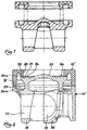
- the inner joining surface 31 is widened in the direction of the bottom region 27, as can be seen particularly clearly from the comparison with FIGS FIG. 1 shown piston blank according to the prior art.
- the wall portion 28 of the combustion bowl 21 is incorporated in the embodiment, for example. Screwed. Furthermore, a circumferential upper cooling channel part 24b of the cooling channel 24 is incorporated. This results in an outer peripheral joining surface 32 and an inner peripheral joining surface 33.
- the outer joining surface 29 of the blank 11 ' corresponds to the outer joining surface 32 of the blank 12'.
- the inner widened joining surface 31 of the blank 11 ' corresponds to the inner joining face 33 of the blank 12'. This means that the two blanks 11 ', 12' along their joining surfaces 29, 31 and 32, 33 can be connected together to form a piston blank 10 '.
- FIG. 2 can be clearly seen, especially in comparison to the prior art according to FIG. 1 , correspond to the inner, widened joining surface 31 of the Blank 11 'and the inner joining surface 33 of the blank 12' according to the invention with each other such that a directed toward the bottom portion 27 of the combustion bowl 21 toward portion 34 of the joining surface 31 remains free.
- a friction welding method provides that one of the two blanks 11 ', 12' is set in rotation until a speed of 1,500 rpm to 2,500 rpm is reached. Now, the blanks 11 ', 12' via their joining surfaces 29, 31 and 32, 33 are brought into contact with each other and under a contact pressure, based on the joining surfaces 29, 31 and 32, 33, of 10 N / mm 2 to 30 N / mm 2 compressed. The rotational movement and the contact pressure generate a friction which heats the joining surfaces 29, 31 or 32, 33.
- the speed and the contact pressure are chosen depending on the materials used so that the joining surfaces 29, 31 and 32, 33 to a temperature close to the melting point of the material or materials heat.
- the rotation is stopped while maintaining the contact pressure, ie the clamping device is braked and stopped as quickly as possible (if possible within less than 1 second).
- the contact pressure is maintained.
- After stopping the contact pressure is increased to a joining pressure, based on the joining surfaces 29, 31 and 32, 33 of 100 N / mm 2 to 140 N / mm 2 , and the blanks 11 ', 12' are about 5 seconds below this Joining pressure pressed together.
- FIG. 3 shows the thus manufactured piston blank 10 '.
- the piston blank 10 ' has friction welds 35, 36 as a result of the friction welding operation described above.
- the piston blank 10 ' is in a conventional manner, depending on the formation of the blanks 11', 12 ', reworked or finished.
- the outer shape, surfaces, combustion bowl, ring section, hub bores, etc. can be finished.
- the freestanding portion 34 of the joining surface 31 is removed, preferably by unscrewing.
- the bottom portion 27 and the wall portion 28 of the combustion bowl 21 are finished.
- the depth of the combustion bowl 21 in the course of the removal of the portion 34 of the joining surface 31 can be chosen freely.
- the blanks 11 ', 12' can be made of a tempered steel or a precipitation hardening steel and tempered before joining.
- the heat-affected zones extend above and below the friction welds 35, 36 each about 1 to 3 mm.
- the hardness of the material is increased by approximately 400 HV (Vickers) compared to the tempered material of the blanks 11 ', 12' outside the heat-affected zones.
- the resulting piston blank 10 ' is then subjected to a heat treatment, namely tempering or stress relief annealing, after friction welding. This heat treatment reduces the hardness of the material by about 200 HV (Vickers) both in the heat affected zones and outside the heat affected zones.
- the hardness difference between the harder heat affected zones and the remaining material of the blanks 11 ', 12' thus remains permanently preserved.
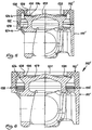
- FIG. 5 shows a further embodiment of a blank 111 'of a piston body 111 and a blank 112' of a piston ring member 112 for a piston 110 according to the invention.
- the blanks 111 ', 112' are produced in the exemplary embodiment by means of a forging process. Subsequently, the blanks 111 ', 112' were preprocessed.
- the embodiment of the bottom portion 127 of the combustion bowl 121 was incorporated, for example. Screwed.
- a circumferential lower cooling passage portion 124a of the cooling passage 124 has been preprocessed. This results in an outer peripheral joining surface 129 and an inner peripheral joining surface 131.
- the inner joining surface 131 is widened in the direction of the bottom region 127, as is particularly clear from the comparison with the in FIG. 1 shown piston blank according to the prior art.
- the wall portion 128 of the combustion bowl 121 incorporated, for example. Screwed. Furthermore, a circumferential upper cooling channel part 124b of the cooling channel 124 is incorporated. This results in an outer peripheral joining surface 132 and an inner peripheral joining surface 133.
- the outer joining surface 129 of the blank 111 ' corresponds to the outer joining surface 132 of the blank 112'.
- the inner widened joining surface 131 of the blank 111 ' corresponds to the inner joining face 133 of the blank 112'. This means that the two blanks 111 ', 112' along their joining surfaces 129, 131 and 132, 133 can be connected together to form a piston blank 110 '.
- the inner widened joining surface 131 of the blank 111 'and the inner joining surface 133 of the blank 112' correspond to one another in such a way that a partial region 134 of the joining surface 131 facing the bottom region 127 of the combustion trough 121 remains free.
- a circumferential widening 137 in the form of a bevel is formed on the inner joining surfaces 133 of the blank 112 'of the piston ring element 112.
- the widening 137 opens in the direction of the bottom region 127 of the combustion bowl 121.
- the maximum axial extension of the widening 137 in the exemplary embodiment is approximately 1 mm in each case.
- the widenings 137 in the embodiment form a space in the form of a right triangle with a maximum axial extent of about 1 mm, in which the molten material is distributed
- the excess material is absorbed in the above-described joints.
- widenings with different geometry can be combined with each other.
- FIG. 6 shows the thus produced piston blank 110 '.
- the piston blank 110 ' has friction welds 135, 136 as a result of the friction welding operation described above.
- FIG. 6 It can also be seen that along Reibsch conductednähte 135, 136 no Reibsch spawulste, as shown in FIG. 3 are shown, have arisen.
- the molten excess material released during the above-described friction welding operation was received by the free space formed by the widening 137 during the friction welding operation.
- the piston blank 110 ' is in a conventional manner, depending on the formation of the blanks 111', 112 ', reworked or finished.
- the outer shape, surfaces, combustion bowl, ring section, hub bores, etc. can be finished.
- the free-standing portion 134 of the joining surface 131 is removed, preferably by unscrewing.
- the bottom portion 127 and the wall portion 128 of the combustion bowl 121 are finished.
- the depth of the combustion bowl 121 in the course of the removal of the portion 134 of the joining surface 131 can be freely selected.
- FIG. 8 shows an enlarged partial view of another embodiment of blanks 211, 212, from which a piston is produced by the method according to the invention.
- a peripheral expansion 237a, 237b in the form of a chamfer are formed on both joining surfaces 229, 231 of the blank 211 'and on both joining surfaces 232, 233 of the blank 212'.
- the widenings 237a extend in the direction of the cooling channel part 224a of the blank 211 '.
- the widenings 237b extend in the direction of the cooling channel part 224b of the blank 212 '.
- the maximum axial extent of the widenings 237a, 237b in the exemplary embodiment is in each case about 1.0 mm, while the radial extent of the widenings 237a, 237b is in each case about 0.5 mm. If the joining surfaces 229, 231 or 232, 233 of the blanks 211 ', 212' come into contact with each other at the beginning of the above-described friction welding, the widening 237a, 237b in the embodiment form two opposing joints with a maximum axial extent of about 2 mm, which can accommodate excess material. Of course, widenings with different geometry can be combined with each other.
Claims (8)
- Procédé servant à fabriquer un piston (10, 110) pour un moteur à combustion interne, comprenant un corps de base de piston (11, 111) et un élément formant un segment de piston (12, 112), le corps de base de piston (11, 111) présentant au moins une tige de piston (15, 115) et au moins une zone de fond (27, 127) d'une cavité de combustion (21, 121), l'élément formant un segment de piston (12, 112) présentant un fond de piston (19, 119), au moins une zone de paroi (28, 128) de la cavité de combustion (21, 121), un cordon de feu (22, 122) périphérique et au moins une proportion d'une partie de segment (23, 123) périphérique pourvue de rainures de segment, et le corps de base de piston (11,111) et l'élément formant un segment de piston (12, 112) formant un canal de refroidissement (24, 124) fermé périphérique, caractérisé par les étapes de procédé qui suivent consistant à :a) fournir une ébauche (11', 111', 211') du corps de base de piston (11, 111), pour lequel une surface d'assemblage (29, 129, 229) périphérique extérieure et une surface d'assemblage (31, 131, 231) périphérique intérieure, élargie en direction de la zone de fond (27, 127) de la cavité de combustion (24, 124), ainsi qu'une proportion de canal de refroidissement (24a, 124a, 224a) inférieure périphérique située entre les deux surfaces d'assemblage (29, 31; 129, 131; 229, 231) sont préalablement usinées ;b) fournir une ébauche (12', 112', 212') de l'élément formant un segment de piston (12, 112), pour lequel une surface d'assemblage (32, 132, 232) extérieure présentant une forme de segment et une surface d'assemblage (33, 133, 133) intérieure présentant une forme de segment ainsi qu'une proportion de canal de refroidissement (24b, 124b, 224b) supérieure périphérique située entre les deux surfaces d'assemblage (32, 33 ; 132, 133 ; 232, 233) sont préalablement usinées;(c) assembler l'ébauche (11', 111', 211) à l'ébauche (12', 112' 212) par l'intermédiaire de leurs surfaces d'assemblage (29, 129, 229 ; 31, 131, 231; 32, 132, 232 ; 33, 133, 232) pour obtenir une ébauche de piston (10', 110') de telle manière qu'une zone partielle (34, 134, 234) de la surface d'assemblage (31, 131, 231) élargie de l'ébauche (11', 111', 211) reste dégagée au moins dans la zone de fond (27, 127) de la cavité de combustion (24, 124) ;(d) usiner ultérieurement et/ou finaliser l'ébauche de piston (10', 110') pour obtenir un piston (10, 110) en retirant la zone partielle (34, 134, 234) de la surface d'assemblage (31, 131, 231) élargie.
- Procédé selon la revendication 1, caractérisé en ce qu'à l'étape (a) ou à l'étape (b), l'ébauche (11', 111', 211') et/ou l'ébauche (12', 112', 212') sont fabriquées au moyen d'un procédé de forgeage et sont immédiatement après préalablement usinées.
- Procédé selon la revendication 1, caractérisé en ce qu'à l'étape (c), l'ébauche (11', 111', 211') est assemblée à l'ébauche (12', 112', 212') au moyen d'un procédé de soudage par friction en formant au moins un cordon de soudage par friction (35, 36, 135, 136).
- Procédé selon la revendication 3, caractérisé en ce qu'avant l'étape (c), des élargissements (137 ; 237a, 237b) périphériques sont pratiqués au niveau d'une surface d'assemblage intérieure et/ou au niveau d'une surface d'assemblage extérieure (133, 229, 231, 232, 233) de l'ébauche (111', 211') et/ou de l'ébauche (112', 212').
- Procédé selon la revendication 4, caractérisé en ce que l'élargissement (137 ; 237a, 237b) périphérique au moins au nombre de un est formé sous la forme d'une surface oblique, d'un chanfrein ou d'une cavité.
- Procédé selon la revendication 4, caractérisé en ce que les élargissements (137 ; 237a, 237b) périphériques sont formés avec une extension axiale allant de 1,0 mm à 1,5 mm et/ou avec une extension radiale d'au moins 0,5 mm.
- Procédé selon la revendication 3, caractérisé en ce que l'ébauche (11', 111', 211') et l'ébauche (12', 112', 212') sont fabriquées à partir d'un acier d'amélioration ou à partir d'un acier à durcissement par précipitation.
- Procédé selon la revendication 7, caractérisé en ce qu'avant l'étape (c) les ébauches (11', 111', 211', 12', 112', 212') sont améliorées, en ce qu'à l'étape (c) les ébauches (11', 111', 211', 12', 112', 212') sont assemblées en formant une zone affectée par la chaleur dans la zone du cordon de soudure par friction (35, 36, 135, 136) au moins au nombre de un, et en ce qu'après l'étape (c) l'ébauche de piston (10', 110') est traitée à chaud par revenu ou par recuit léger de détensionnement en obtenant la/les zone(s) affectée(s) par la chaleur.
Applications Claiming Priority (2)
| Application Number | Priority Date | Filing Date | Title |
|---|---|---|---|
| DE102012008947A DE102012008947A1 (de) | 2012-05-05 | 2012-05-05 | Verfahren zur Herstellung eines Kolbens für einen Verbrennungsmotor |
| PCT/DE2013/000241 WO2013167105A1 (fr) | 2012-05-05 | 2013-05-03 | Procédé de fabrication d'un piston pour un moteur à combustion |
Publications (2)
| Publication Number | Publication Date |
|---|---|
| EP2844424A1 EP2844424A1 (fr) | 2015-03-11 |
| EP2844424B1 true EP2844424B1 (fr) | 2016-05-25 |
Family
ID=48914022
Family Applications (1)
| Application Number | Title | Priority Date | Filing Date |
|---|---|---|---|
| EP13744420.4A Active EP2844424B1 (fr) | 2012-05-05 | 2013-05-03 | Procédé de fabrication d'un piston pour un moteur à combustion interne |
Country Status (7)
| Country | Link |
|---|---|
| US (1) | US9308607B2 (fr) |
| EP (1) | EP2844424B1 (fr) |
| JP (1) | JP6143847B2 (fr) |
| CN (1) | CN104379301B (fr) |
| BR (1) | BR112014027531A2 (fr) |
| DE (1) | DE102012008947A1 (fr) |
| WO (1) | WO2013167105A1 (fr) |
Cited By (1)
| Publication number | Priority date | Publication date | Assignee | Title |
|---|---|---|---|---|
| EP2969366B1 (fr) * | 2013-03-14 | 2019-01-30 | Mahle International GmbH | Assemblage de pistons soudés |
Families Citing this family (11)
| Publication number | Priority date | Publication date | Assignee | Title |
|---|---|---|---|---|
| BR112015005723A2 (pt) * | 2012-09-27 | 2017-07-04 | Ks Kolbenschmidt Gmbh | pistão construído em duas peças de uma máquina de combustão interna |
| EP3234330B1 (fr) * | 2014-12-19 | 2023-12-06 | Tenneco Inc. | Piston à galerie de refroidissement comportant une entrée d'huile améliorée et procédé de construction de celui-ci |
| EP3356666A1 (fr) * | 2015-10-01 | 2018-08-08 | KS Kolbenschmidt GmbH | Piston en deux parties à canal de refroidissement ouvert |
| EP3377748A1 (fr) * | 2015-11-17 | 2018-09-26 | KS Kolbenschmidt GmbH | Piston pour moteur à combustion interne |
| US11162453B2 (en) | 2016-05-04 | 2021-11-02 | Ks Kolbenschmidt Gmbh | Piston |
| WO2018092088A1 (fr) * | 2016-11-20 | 2018-05-24 | Dahan Oded | Piston léger |
| DE102017203433A1 (de) * | 2017-03-02 | 2018-09-06 | Mahle International Gmbh | Verfahren zur Herstellung eines Kolbens |
| DE102017210818A1 (de) * | 2017-06-27 | 2018-12-27 | Mahle International Gmbh | Verfahren zur Herstellung eines Kolbens für eine Brennkraftmaschine aus einem Kolbenoberteil und aus einem Kolbenunterteil |
| US20190010892A1 (en) * | 2017-07-10 | 2019-01-10 | Mahle International Gmbh | Piston with a cooling channel insert |
| CN113122771B (zh) * | 2019-12-31 | 2022-01-14 | 中内凯思汽车新动力系统有限公司 | 一种高性能摩擦焊接钢质活塞及其制备方法 |
| DE102021203241A1 (de) | 2021-03-30 | 2022-10-06 | Mahle International Gmbh | Kolben für eine Brennkraftmaschine und Verfahren zur Herstellung des Kolbens |
Citations (6)
| Publication number | Priority date | Publication date | Assignee | Title |
|---|---|---|---|---|
| DE4134529C2 (de) | 1990-10-18 | 2002-02-14 | Ae Goetze Inc Carolina Ann Arb | Verfahren zur Herstellung eines Kolbenkopfes mit Kühlkammer und nach diesem Verfahren hergestellter Kolbenkopf |
| DE102006002949A1 (de) | 2006-01-21 | 2007-08-02 | Ks Kolbenschmidt Gmbh | Kühlkanalkolben für eine Brennkraftmaschine |
| DE102006031094A1 (de) | 2006-07-05 | 2008-01-10 | Ks Kolbenschmidt Gmbh | Kühlmediumübertritt im Kolben mit kleiner Kompressionshöhe |
| DE102009058176A1 (de) | 2008-12-15 | 2011-01-13 | Ks Kolbenschmidt Gmbh | Einteiliger Kolben aus Stral mit optimiertem Mehrkomponentenkühlsystem |
| DE102010033881A1 (de) | 2010-08-10 | 2012-02-16 | Mahle International Gmbh | Kolben für einen Verbrennungsmotor und Verfahren zu seiner Herstellung |
| DE102011100521A1 (de) | 2010-08-10 | 2012-02-16 | Mahle International Gmbh | Kolben für einen Verbrennungsmotor und Verfahren zu seiner Herstellung |
Family Cites Families (8)
| Publication number | Priority date | Publication date | Assignee | Title |
|---|---|---|---|---|
| JPH1136978A (ja) * | 1997-07-16 | 1999-02-09 | Unisia Jecs Corp | 内燃機関用ピストン |
| DE102008038325A1 (de) * | 2007-12-20 | 2009-06-25 | Mahle International Gmbh | Verfahren zum Befestigen eines Ringelementes auf einem Kolben für einen Verbrennungsmotor |
| DE102008034430B4 (de) * | 2008-07-24 | 2015-02-19 | Ks Kolbenschmidt Gmbh | Reibgeschweißter Stahlkolben mit optimiertem Kühlkanal |
| DE102008045456A1 (de) * | 2008-09-02 | 2010-03-04 | Mahle International Gmbh | Kolben für einen Verbrennungsmotor |
| US8146560B2 (en) * | 2008-11-05 | 2012-04-03 | Mahle International Gmbh | Multi-part piston for an internal combustion engine and method for its production |
| US9970384B2 (en) * | 2009-11-06 | 2018-05-15 | Federal-Mogul Llc | Steel piston with cooling gallery and method of construction thereof |
| US8807109B2 (en) | 2009-11-06 | 2014-08-19 | Federal-Mogul Corporation | Steel piston with cooling gallery and method of construction thereof |
| US8631573B2 (en) * | 2010-08-10 | 2014-01-21 | Mahle International Gmbh | Piston for an internal combustion engine and method for its production |
-
2012
- 2012-05-05 DE DE102012008947A patent/DE102012008947A1/de not_active Withdrawn
-
2013
- 2013-05-03 WO PCT/DE2013/000241 patent/WO2013167105A1/fr active Application Filing
- 2013-05-03 CN CN201380032920.5A patent/CN104379301B/zh active Active
- 2013-05-03 EP EP13744420.4A patent/EP2844424B1/fr active Active
- 2013-05-03 BR BR112014027531A patent/BR112014027531A2/pt not_active Application Discontinuation
- 2013-05-03 JP JP2015510641A patent/JP6143847B2/ja not_active Expired - Fee Related
- 2013-05-03 US US14/398,787 patent/US9308607B2/en active Active
Patent Citations (6)
| Publication number | Priority date | Publication date | Assignee | Title |
|---|---|---|---|---|
| DE4134529C2 (de) | 1990-10-18 | 2002-02-14 | Ae Goetze Inc Carolina Ann Arb | Verfahren zur Herstellung eines Kolbenkopfes mit Kühlkammer und nach diesem Verfahren hergestellter Kolbenkopf |
| DE102006002949A1 (de) | 2006-01-21 | 2007-08-02 | Ks Kolbenschmidt Gmbh | Kühlkanalkolben für eine Brennkraftmaschine |
| DE102006031094A1 (de) | 2006-07-05 | 2008-01-10 | Ks Kolbenschmidt Gmbh | Kühlmediumübertritt im Kolben mit kleiner Kompressionshöhe |
| DE102009058176A1 (de) | 2008-12-15 | 2011-01-13 | Ks Kolbenschmidt Gmbh | Einteiliger Kolben aus Stral mit optimiertem Mehrkomponentenkühlsystem |
| DE102010033881A1 (de) | 2010-08-10 | 2012-02-16 | Mahle International Gmbh | Kolben für einen Verbrennungsmotor und Verfahren zu seiner Herstellung |
| DE102011100521A1 (de) | 2010-08-10 | 2012-02-16 | Mahle International Gmbh | Kolben für einen Verbrennungsmotor und Verfahren zu seiner Herstellung |
Cited By (1)
| Publication number | Priority date | Publication date | Assignee | Title |
|---|---|---|---|---|
| EP2969366B1 (fr) * | 2013-03-14 | 2019-01-30 | Mahle International GmbH | Assemblage de pistons soudés |
Also Published As
| Publication number | Publication date |
|---|---|
| CN104379301B (zh) | 2016-11-16 |
| US20150135533A1 (en) | 2015-05-21 |
| EP2844424A1 (fr) | 2015-03-11 |
| US9308607B2 (en) | 2016-04-12 |
| CN104379301A (zh) | 2015-02-25 |
| WO2013167105A1 (fr) | 2013-11-14 |
| DE102012008947A1 (de) | 2013-11-07 |
| BR112014027531A2 (pt) | 2017-06-27 |
| JP6143847B2 (ja) | 2017-06-07 |
| JP2015522430A (ja) | 2015-08-06 |
Similar Documents
| Publication | Publication Date | Title |
|---|---|---|
| EP2844424B1 (fr) | Procédé de fabrication d'un piston pour un moteur à combustion interne | |
| EP2603685B1 (fr) | Piston pour un moteur à combustion interne et procédé de fabrication correspondant | |
| EP2681437B1 (fr) | Piston pour moteur à combustion interne et son procédé de production | |
| EP2976179B1 (fr) | Procédé de production d'un piston pour moteur à combustion interne | |
| WO2013097839A2 (fr) | Piston pour moteur à combustion interne et procédé de fabrication dudit piston | |
| EP2681435A2 (fr) | Piston pour un moteur à combustion interne et procédé de fabrication | |
| DE102008056203A1 (de) | Mehrteiliger Kolben für einen Verbrennungsmotor und Verfahren zu seiner Herstellung | |
| DE102011013067A1 (de) | Verfahren zur Herstellung eines Kolbens für einen Verbrennungsmotor | |
| EP2603347B1 (fr) | Piston pour un moteur à combustion interne et procédé de fabrication correspondant | |
| WO2018158092A1 (fr) | Procédé de fabrication d'un piston | |
| WO2003093654A1 (fr) | Came monobloc, son procede de fabrication, et assemblage d'un arbre de commande ou arbre a came | |
| DE102008063947B4 (de) | Kolben mit standardisiertem Kolbenboden bei variabler Kompressionshöhe | |
| EP2976181B1 (fr) | Procédé de production d'un piston pour un moteur à combustion interne | |
| WO2017125580A1 (fr) | Piston muni de trois rainures de segment et d'une autre rainure présentant un joint de séparation | |
| EP2976180B1 (fr) | Procédé de production d'un piston pour moteur à combustion interne | |
| WO2015104013A1 (fr) | Piston pour moteur à combustion interne et son procédé de fabrication | |
| DE10311148A1 (de) | Verfahren zur Herstellung eines geschmiedeten Kolbens für einen Verbrennungsmotor | |
| CH714422A1 (de) | Verfahren zur Herstellung einer Trommel einer Axialkolbenmaschine. | |
| EP3063400A1 (fr) | Piston destiné à un moteur à combustion interne et procédé de fabrication dudit piston | |
| WO2013004219A1 (fr) | Piston pour moteur à combustion interne et son procédé de fabrication |
Legal Events
| Date | Code | Title | Description |
|---|---|---|---|
| PUAI | Public reference made under article 153(3) epc to a published international application that has entered the european phase |
Free format text: ORIGINAL CODE: 0009012 |
|
| 17P | Request for examination filed |
Effective date: 20141205 |
|
| AK | Designated contracting states |
Kind code of ref document: A1 Designated state(s): AL AT BE BG CH CY CZ DE DK EE ES FI FR GB GR HR HU IE IS IT LI LT LU LV MC MK MT NL NO PL PT RO RS SE SI SK SM TR |
|
| AX | Request for extension of the european patent |
Extension state: BA ME |
|
| DAX | Request for extension of the european patent (deleted) | ||
| GRAP | Despatch of communication of intention to grant a patent |
Free format text: ORIGINAL CODE: EPIDOSNIGR1 |
|
| INTG | Intention to grant announced |
Effective date: 20160205 |
|
| RIC1 | Information provided on ipc code assigned before grant |
Ipc: B23K 20/12 20060101ALI20160122BHEP Ipc: B23P 15/10 20060101AFI20160122BHEP Ipc: F02F 3/00 20060101ALI20160122BHEP Ipc: F16J 1/00 20060101ALI20160122BHEP Ipc: F02F 3/22 20060101ALN20160122BHEP |
|
| GRAS | Grant fee paid |
Free format text: ORIGINAL CODE: EPIDOSNIGR3 |
|
| GRAA | (expected) grant |
Free format text: ORIGINAL CODE: 0009210 |
|
| AK | Designated contracting states |
Kind code of ref document: B1 Designated state(s): AL AT BE BG CH CY CZ DE DK EE ES FI FR GB GR HR HU IE IS IT LI LT LU LV MC MK MT NL NO PL PT RO RS SE SI SK SM TR |
|
| REG | Reference to a national code |
Ref country code: GB Ref legal event code: FG4D Free format text: NOT ENGLISH |
|
| REG | Reference to a national code |
Ref country code: CH Ref legal event code: EP |
|
| REG | Reference to a national code |
Ref country code: IE Ref legal event code: FG4D Free format text: LANGUAGE OF EP DOCUMENT: GERMAN Ref country code: AT Ref legal event code: REF Ref document number: 801856 Country of ref document: AT Kind code of ref document: T Effective date: 20160615 |
|
| REG | Reference to a national code |
Ref country code: DE Ref legal event code: R096 Ref document number: 502013003207 Country of ref document: DE |
|
| REG | Reference to a national code |
Ref country code: LT Ref legal event code: MG4D |
|
| REG | Reference to a national code |
Ref country code: NL Ref legal event code: MP Effective date: 20160525 |
|
| PG25 | Lapsed in a contracting state [announced via postgrant information from national office to epo] |
Ref country code: LT Free format text: LAPSE BECAUSE OF FAILURE TO SUBMIT A TRANSLATION OF THE DESCRIPTION OR TO PAY THE FEE WITHIN THE PRESCRIBED TIME-LIMIT Effective date: 20160525 Ref country code: NL Free format text: LAPSE BECAUSE OF FAILURE TO SUBMIT A TRANSLATION OF THE DESCRIPTION OR TO PAY THE FEE WITHIN THE PRESCRIBED TIME-LIMIT Effective date: 20160525 Ref country code: NO Free format text: LAPSE BECAUSE OF FAILURE TO SUBMIT A TRANSLATION OF THE DESCRIPTION OR TO PAY THE FEE WITHIN THE PRESCRIBED TIME-LIMIT Effective date: 20160825 Ref country code: FI Free format text: LAPSE BECAUSE OF FAILURE TO SUBMIT A TRANSLATION OF THE DESCRIPTION OR TO PAY THE FEE WITHIN THE PRESCRIBED TIME-LIMIT Effective date: 20160525 |
|
| PG25 | Lapsed in a contracting state [announced via postgrant information from national office to epo] |
Ref country code: PT Free format text: LAPSE BECAUSE OF FAILURE TO SUBMIT A TRANSLATION OF THE DESCRIPTION OR TO PAY THE FEE WITHIN THE PRESCRIBED TIME-LIMIT Effective date: 20160926 Ref country code: SE Free format text: LAPSE BECAUSE OF FAILURE TO SUBMIT A TRANSLATION OF THE DESCRIPTION OR TO PAY THE FEE WITHIN THE PRESCRIBED TIME-LIMIT Effective date: 20160525 Ref country code: ES Free format text: LAPSE BECAUSE OF FAILURE TO SUBMIT A TRANSLATION OF THE DESCRIPTION OR TO PAY THE FEE WITHIN THE PRESCRIBED TIME-LIMIT Effective date: 20160525 Ref country code: RS Free format text: LAPSE BECAUSE OF FAILURE TO SUBMIT A TRANSLATION OF THE DESCRIPTION OR TO PAY THE FEE WITHIN THE PRESCRIBED TIME-LIMIT Effective date: 20160525 Ref country code: GR Free format text: LAPSE BECAUSE OF FAILURE TO SUBMIT A TRANSLATION OF THE DESCRIPTION OR TO PAY THE FEE WITHIN THE PRESCRIBED TIME-LIMIT Effective date: 20160826 Ref country code: LV Free format text: LAPSE BECAUSE OF FAILURE TO SUBMIT A TRANSLATION OF THE DESCRIPTION OR TO PAY THE FEE WITHIN THE PRESCRIBED TIME-LIMIT Effective date: 20160525 |
|
| PG25 | Lapsed in a contracting state [announced via postgrant information from national office to epo] |
Ref country code: IT Free format text: LAPSE BECAUSE OF FAILURE TO SUBMIT A TRANSLATION OF THE DESCRIPTION OR TO PAY THE FEE WITHIN THE PRESCRIBED TIME-LIMIT Effective date: 20160525 |
|
| PG25 | Lapsed in a contracting state [announced via postgrant information from national office to epo] |
Ref country code: RO Free format text: LAPSE BECAUSE OF FAILURE TO SUBMIT A TRANSLATION OF THE DESCRIPTION OR TO PAY THE FEE WITHIN THE PRESCRIBED TIME-LIMIT Effective date: 20160525 Ref country code: SK Free format text: LAPSE BECAUSE OF FAILURE TO SUBMIT A TRANSLATION OF THE DESCRIPTION OR TO PAY THE FEE WITHIN THE PRESCRIBED TIME-LIMIT Effective date: 20160525 Ref country code: CZ Free format text: LAPSE BECAUSE OF FAILURE TO SUBMIT A TRANSLATION OF THE DESCRIPTION OR TO PAY THE FEE WITHIN THE PRESCRIBED TIME-LIMIT Effective date: 20160525 Ref country code: DK Free format text: LAPSE BECAUSE OF FAILURE TO SUBMIT A TRANSLATION OF THE DESCRIPTION OR TO PAY THE FEE WITHIN THE PRESCRIBED TIME-LIMIT Effective date: 20160525 Ref country code: EE Free format text: LAPSE BECAUSE OF FAILURE TO SUBMIT A TRANSLATION OF THE DESCRIPTION OR TO PAY THE FEE WITHIN THE PRESCRIBED TIME-LIMIT Effective date: 20160525 |
|
| REG | Reference to a national code |
Ref country code: DE Ref legal event code: R026 Ref document number: 502013003207 Country of ref document: DE |
|
| PG25 | Lapsed in a contracting state [announced via postgrant information from national office to epo] |
Ref country code: SM Free format text: LAPSE BECAUSE OF FAILURE TO SUBMIT A TRANSLATION OF THE DESCRIPTION OR TO PAY THE FEE WITHIN THE PRESCRIBED TIME-LIMIT Effective date: 20160525 Ref country code: PL Free format text: LAPSE BECAUSE OF FAILURE TO SUBMIT A TRANSLATION OF THE DESCRIPTION OR TO PAY THE FEE WITHIN THE PRESCRIBED TIME-LIMIT Effective date: 20160525 |
|
| PLBI | Opposition filed |
Free format text: ORIGINAL CODE: 0009260 |
|
| PLAX | Notice of opposition and request to file observation + time limit sent |
Free format text: ORIGINAL CODE: EPIDOSNOBS2 |
|
| 26 | Opposition filed |
Opponent name: FEDERAL-MOGUL NUERNBERG GMBH Effective date: 20170227 |
|
| REG | Reference to a national code |
Ref country code: FR Ref legal event code: PLFP Year of fee payment: 5 |
|
| PG25 | Lapsed in a contracting state [announced via postgrant information from national office to epo] |
Ref country code: SI Free format text: LAPSE BECAUSE OF FAILURE TO SUBMIT A TRANSLATION OF THE DESCRIPTION OR TO PAY THE FEE WITHIN THE PRESCRIBED TIME-LIMIT Effective date: 20160525 |
|
| PLBB | Reply of patent proprietor to notice(s) of opposition received |
Free format text: ORIGINAL CODE: EPIDOSNOBS3 |
|
| PG25 | Lapsed in a contracting state [announced via postgrant information from national office to epo] |
Ref country code: LU Free format text: LAPSE BECAUSE OF NON-PAYMENT OF DUE FEES Effective date: 20170531 |
|
| REG | Reference to a national code |
Ref country code: CH Ref legal event code: PL |
|
| GBPC | Gb: european patent ceased through non-payment of renewal fee |
Effective date: 20170503 |
|
| PG25 | Lapsed in a contracting state [announced via postgrant information from national office to epo] |
Ref country code: MC Free format text: LAPSE BECAUSE OF FAILURE TO SUBMIT A TRANSLATION OF THE DESCRIPTION OR TO PAY THE FEE WITHIN THE PRESCRIBED TIME-LIMIT Effective date: 20160525 |
|
| REG | Reference to a national code |
Ref country code: IE Ref legal event code: MM4A |
|
| PG25 | Lapsed in a contracting state [announced via postgrant information from national office to epo] |
Ref country code: LI Free format text: LAPSE BECAUSE OF NON-PAYMENT OF DUE FEES Effective date: 20170531 Ref country code: CH Free format text: LAPSE BECAUSE OF NON-PAYMENT OF DUE FEES Effective date: 20170531 |
|
| PG25 | Lapsed in a contracting state [announced via postgrant information from national office to epo] |
Ref country code: LU Free format text: LAPSE BECAUSE OF NON-PAYMENT OF DUE FEES Effective date: 20170503 |
|
| REG | Reference to a national code |
Ref country code: BE Ref legal event code: MM Effective date: 20170531 |
|
| PG25 | Lapsed in a contracting state [announced via postgrant information from national office to epo] |
Ref country code: IE Free format text: LAPSE BECAUSE OF NON-PAYMENT OF DUE FEES Effective date: 20170503 Ref country code: GB Free format text: LAPSE BECAUSE OF NON-PAYMENT OF DUE FEES Effective date: 20170503 |
|
| REG | Reference to a national code |
Ref country code: DE Ref legal event code: R100 Ref document number: 502013003207 Country of ref document: DE |
|
| REG | Reference to a national code |
Ref country code: FR Ref legal event code: PLFP Year of fee payment: 6 |
|
| PLCK | Communication despatched that opposition was rejected |
Free format text: ORIGINAL CODE: EPIDOSNREJ1 |
|
| PG25 | Lapsed in a contracting state [announced via postgrant information from national office to epo] |
Ref country code: BE Free format text: LAPSE BECAUSE OF NON-PAYMENT OF DUE FEES Effective date: 20170531 |
|
| PG25 | Lapsed in a contracting state [announced via postgrant information from national office to epo] |
Ref country code: MT Free format text: LAPSE BECAUSE OF FAILURE TO SUBMIT A TRANSLATION OF THE DESCRIPTION OR TO PAY THE FEE WITHIN THE PRESCRIBED TIME-LIMIT Effective date: 20160525 |
|
| PLBN | Opposition rejected |
Free format text: ORIGINAL CODE: 0009273 |
|
| STAA | Information on the status of an ep patent application or granted ep patent |
Free format text: STATUS: OPPOSITION REJECTED |
|
| PG25 | Lapsed in a contracting state [announced via postgrant information from national office to epo] |
Ref country code: AL Free format text: LAPSE BECAUSE OF FAILURE TO SUBMIT A TRANSLATION OF THE DESCRIPTION OR TO PAY THE FEE WITHIN THE PRESCRIBED TIME-LIMIT Effective date: 20160525 |
|
| 27O | Opposition rejected |
Effective date: 20180518 |
|
| PG25 | Lapsed in a contracting state [announced via postgrant information from national office to epo] |
Ref country code: HU Free format text: LAPSE BECAUSE OF FAILURE TO SUBMIT A TRANSLATION OF THE DESCRIPTION OR TO PAY THE FEE WITHIN THE PRESCRIBED TIME-LIMIT; INVALID AB INITIO Effective date: 20130503 |
|
| REG | Reference to a national code |
Ref country code: AT Ref legal event code: MM01 Ref document number: 801856 Country of ref document: AT Kind code of ref document: T Effective date: 20180503 |
|
| PG25 | Lapsed in a contracting state [announced via postgrant information from national office to epo] |
Ref country code: BG Free format text: LAPSE BECAUSE OF FAILURE TO SUBMIT A TRANSLATION OF THE DESCRIPTION OR TO PAY THE FEE WITHIN THE PRESCRIBED TIME-LIMIT Effective date: 20160525 |
|
| PGFP | Annual fee paid to national office [announced via postgrant information from national office to epo] |
Ref country code: FR Payment date: 20190528 Year of fee payment: 7 |
|
| PG25 | Lapsed in a contracting state [announced via postgrant information from national office to epo] |
Ref country code: AT Free format text: LAPSE BECAUSE OF NON-PAYMENT OF DUE FEES Effective date: 20180503 Ref country code: CY Free format text: LAPSE BECAUSE OF FAILURE TO SUBMIT A TRANSLATION OF THE DESCRIPTION OR TO PAY THE FEE WITHIN THE PRESCRIBED TIME-LIMIT Effective date: 20160525 |
|
| PG25 | Lapsed in a contracting state [announced via postgrant information from national office to epo] |
Ref country code: MK Free format text: LAPSE BECAUSE OF FAILURE TO SUBMIT A TRANSLATION OF THE DESCRIPTION OR TO PAY THE FEE WITHIN THE PRESCRIBED TIME-LIMIT Effective date: 20160525 |
|
| PG25 | Lapsed in a contracting state [announced via postgrant information from national office to epo] |
Ref country code: TR Free format text: LAPSE BECAUSE OF FAILURE TO SUBMIT A TRANSLATION OF THE DESCRIPTION OR TO PAY THE FEE WITHIN THE PRESCRIBED TIME-LIMIT Effective date: 20160525 |
|
| PG25 | Lapsed in a contracting state [announced via postgrant information from national office to epo] |
Ref country code: HR Free format text: LAPSE BECAUSE OF FAILURE TO SUBMIT A TRANSLATION OF THE DESCRIPTION OR TO PAY THE FEE WITHIN THE PRESCRIBED TIME-LIMIT Effective date: 20160525 |
|
| PG25 | Lapsed in a contracting state [announced via postgrant information from national office to epo] |
Ref country code: IS Free format text: LAPSE BECAUSE OF FAILURE TO SUBMIT A TRANSLATION OF THE DESCRIPTION OR TO PAY THE FEE WITHIN THE PRESCRIBED TIME-LIMIT Effective date: 20160925 |
|
| PG25 | Lapsed in a contracting state [announced via postgrant information from national office to epo] |
Ref country code: FR Free format text: LAPSE BECAUSE OF NON-PAYMENT OF DUE FEES Effective date: 20200531 |
|
| PGFP | Annual fee paid to national office [announced via postgrant information from national office to epo] |
Ref country code: DE Payment date: 20230519 Year of fee payment: 11 |