EP2844211B1 - Physiologischer sensor - Google Patents
Physiologischer sensor Download PDFInfo
- Publication number
- EP2844211B1 EP2844211B1 EP13728533.4A EP13728533A EP2844211B1 EP 2844211 B1 EP2844211 B1 EP 2844211B1 EP 13728533 A EP13728533 A EP 13728533A EP 2844211 B1 EP2844211 B1 EP 2844211B1
- Authority
- EP
- European Patent Office
- Prior art keywords
- movable
- pressure transducer
- lumen
- lumen end
- pressure
- Prior art date
- Legal status (The legal status is an assumption and is not a legal conclusion. Google has not performed a legal analysis and makes no representation as to the accuracy of the status listed.)
- Active
Links
- 230000006835 compression Effects 0.000 claims description 87
- 238000007906 compression Methods 0.000 claims description 87
- 238000002680 cardiopulmonary resuscitation Methods 0.000 claims description 43
- 239000007788 liquid Substances 0.000 claims description 37
- 230000002706 hydrostatic effect Effects 0.000 claims description 5
- 238000005259 measurement Methods 0.000 description 12
- 238000000034 method Methods 0.000 description 10
- 238000000465 moulding Methods 0.000 description 9
- 238000010586 diagram Methods 0.000 description 8
- 238000009530 blood pressure measurement Methods 0.000 description 5
- 230000000694 effects Effects 0.000 description 4
- 230000007774 longterm Effects 0.000 description 2
- 230000004083 survival effect Effects 0.000 description 2
- 101100440934 Candida albicans (strain SC5314 / ATCC MYA-2876) CPH1 gene Proteins 0.000 description 1
- 101100273252 Candida parapsilosis SAPP1 gene Proteins 0.000 description 1
- 208000010496 Heart Arrest Diseases 0.000 description 1
- 230000002730 additional effect Effects 0.000 description 1
- 230000009286 beneficial effect Effects 0.000 description 1
- 230000002612 cardiopulmonary effect Effects 0.000 description 1
- 230000003467 diminishing effect Effects 0.000 description 1
- 238000006073 displacement reaction Methods 0.000 description 1
- JEIPFZHSYJVQDO-UHFFFAOYSA-N ferric oxide Chemical compound O=[Fe]O[Fe]=O JEIPFZHSYJVQDO-UHFFFAOYSA-N 0.000 description 1
- 239000006260 foam Substances 0.000 description 1
- 238000012544 monitoring process Methods 0.000 description 1
- 230000001960 triggered effect Effects 0.000 description 1
Images


Classifications
-
- A—HUMAN NECESSITIES
- A61—MEDICAL OR VETERINARY SCIENCE; HYGIENE
- A61B—DIAGNOSIS; SURGERY; IDENTIFICATION
- A61B5/00—Measuring for diagnostic purposes; Identification of persons
- A61B5/103—Detecting, measuring or recording devices for testing the shape, pattern, colour, size or movement of the body or parts thereof, for diagnostic purposes
- A61B5/107—Measuring physical dimensions, e.g. size of the entire body or parts thereof
-
- A—HUMAN NECESSITIES
- A61—MEDICAL OR VETERINARY SCIENCE; HYGIENE
- A61H—PHYSICAL THERAPY APPARATUS, e.g. DEVICES FOR LOCATING OR STIMULATING REFLEX POINTS IN THE BODY; ARTIFICIAL RESPIRATION; MASSAGE; BATHING DEVICES FOR SPECIAL THERAPEUTIC OR HYGIENIC PURPOSES OR SPECIFIC PARTS OF THE BODY
- A61H31/00—Artificial respiration or heart stimulation, e.g. heart massage
- A61H31/004—Heart stimulation
- A61H31/005—Heart stimulation with feedback for the user
-
- A—HUMAN NECESSITIES
- A61—MEDICAL OR VETERINARY SCIENCE; HYGIENE
- A61B—DIAGNOSIS; SURGERY; IDENTIFICATION
- A61B5/00—Measuring for diagnostic purposes; Identification of persons
- A61B5/103—Detecting, measuring or recording devices for testing the shape, pattern, colour, size or movement of the body or parts thereof, for diagnostic purposes
- A61B5/1036—Measuring load distribution, e.g. podologic studies
-
- A—HUMAN NECESSITIES
- A61—MEDICAL OR VETERINARY SCIENCE; HYGIENE
- A61H—PHYSICAL THERAPY APPARATUS, e.g. DEVICES FOR LOCATING OR STIMULATING REFLEX POINTS IN THE BODY; ARTIFICIAL RESPIRATION; MASSAGE; BATHING DEVICES FOR SPECIAL THERAPEUTIC OR HYGIENIC PURPOSES OR SPECIFIC PARTS OF THE BODY
- A61H31/00—Artificial respiration or heart stimulation, e.g. heart massage
- A61H31/004—Heart stimulation
- A61H31/006—Power driven
-
- A—HUMAN NECESSITIES
- A61—MEDICAL OR VETERINARY SCIENCE; HYGIENE
- A61H—PHYSICAL THERAPY APPARATUS, e.g. DEVICES FOR LOCATING OR STIMULATING REFLEX POINTS IN THE BODY; ARTIFICIAL RESPIRATION; MASSAGE; BATHING DEVICES FOR SPECIAL THERAPEUTIC OR HYGIENIC PURPOSES OR SPECIFIC PARTS OF THE BODY
- A61H31/00—Artificial respiration or heart stimulation, e.g. heart massage
- A61H31/004—Heart stimulation
- A61H31/007—Manual driven
-
- A—HUMAN NECESSITIES
- A61—MEDICAL OR VETERINARY SCIENCE; HYGIENE
- A61H—PHYSICAL THERAPY APPARATUS, e.g. DEVICES FOR LOCATING OR STIMULATING REFLEX POINTS IN THE BODY; ARTIFICIAL RESPIRATION; MASSAGE; BATHING DEVICES FOR SPECIAL THERAPEUTIC OR HYGIENIC PURPOSES OR SPECIFIC PARTS OF THE BODY
- A61H2201/00—Characteristics of apparatus not provided for in the preceding codes
- A61H2201/50—Control means thereof
- A61H2201/5058—Sensors or detectors
- A61H2201/5071—Pressure sensors
Definitions
- the invention relates to the field of cardiopulmonary resuscitation.
- the invention addresses a cardiopulmonary resuscitation apparatus comprising a physiological sensor.
- Cardiopulmonary resuscitation is a well-known technique for increasing the chance for survival from cardiac arrest. However, it is very difficult to perform manual cardiopulmonary resuscitation with consistent high quality.
- A-CPR Automated CPR
- the CPR performance value is often given by deviation to a target depth and a target frequency of the compressions. Typically, the target depth is around 5.0 cm and the target frequency is around 100 compressions per minute.
- the frequency of the compressions is generally measured by measuring the time between compression peaks.
- Sensors devices have been developed, to give feedback on the achieved compression depth.
- the known sensor devices are based on either a spring or an accelerometer based measurement, to measure the relative compression depth.
- the known sensor devices suffer several drawbacks.
- standard accelerometer based compression depth measurements an important error is made when a patient is laying on a compliant surface, such as a standard mattress. Because of the chest compressions, both the patient and the compliant surface are compressed on the same time, effects that are both measured with the accelerometer. The amount the compliant surface is compressed can be up to half the amount the chest is compressed. Therefore an accelerometer based compression depth of 5cm, can be only +-3cm when not corrected for the compliant surface. Standard correction is not possible because it is not known beforehand if resuscitation is happening on a hard or compliant surface.
- the amount of compliant surface compression depends on the surface itself, the absolute weight of the patient, the weight distribution, etc, which makes determining the correction factor impossible.
- United States Patent application, publication umber 2012/0083720 discloses a reference sensor for CPR feedback for measuring a net depth compression using magnetic field sensors or an accelerometer.
- US 2004/082888 A1 discloses a cardio pulmonary resuscitation apparatus comprising a compression depth sensor for measuring a compression depth of a patient's chest during cardio pulmonary resuscitation.
- Another height measuring sensor is known from the French patent application, application number 2 842 900 , disclosing sensor for measuring a change in height between measuring points.
- cardio pulmonary resuscitation apparatus comprising a compression sensor which is adapted to measure an absolute chest compression height.
- a cardio pulmonary resuscitation apparatus as claimed in claim 1 is provided.
- the first movable lumen end comprises fixation means for attachment to a first movable element.
- the fixation means could be positioned on any movable element whose displacement should be measured, e.g. directly on a patient's chest or on a compression pad during resuscitation.
- the compression depth sensor comprises a second pressure transducer, attachable to said fixed element, a second liquid filled lumen, having a second fixed lumen end attachable to the second pressure transducer and a second movable lumen end being movable between a third position and a fourth position, a distance between the third and fourth positions defining a moving height, whereby the second pressure transducer is adapted to measure the moving height by measuring the liquid pressure being in the second lumen during movement of the second movable lumen end between the third and the fourth positions, and a subtractor for deriving a difference between the first compression depth and the moving height.
- the second movable lumen end may comprise second fixation means for fixation below a patient.
- the second fixation means may be useful to make an additional position measurement, depending on which application the compression sensor is used.
- the additional position measurements can be performed below the patient, e.g. on the surface on which the patient is laying, which can be compliant.
- the additional position measurement can be used to correct the compression depth measurements, by taking into account the compliance of the surface.
- the first pressure transducer and the second pressure transducer are one of a strain gage transducer or a tip pressure transducer.
- the present invention further proposes a Cardio Pulmonary Resuscitation (CPR) apparatus, comprising a compression depth sensor, wherein the first movable element is a compression pad.
- the compression depth sensor is adapted to derive the absolute position of the compression pad.
- a method for measuring a compression depth comprising measuring, by a first pressure transducer, attachable to a fixed element, a liquid pressure in a first liquid filled lumen, said first liquid filled lumen having a first fixed lumen end attachable to the first pressure transducer and a first movable lumen end being movable between a first position and a second position, during movement of the first movable lumen end between the first position and the second position, wherein a distance between the first and second position corresponds to the compression depth.
- the method comprises measuring, by a second pressure transducer, another pressure corresponding to a moving height by measuring a liquid pressure in a second liquid filled lumen, said second liquid filled lumen having a second fixed lumen end attachable to the second pressure transducer and a second movable lumen end being movable between a third position and a fourth position, during movement of the second movable lumen end between the third and the fourth positions.
- the method comprises deriving a difference between the first compression depth and the moving height.
- chest height and molding effects are measured by measuring a DC component of the differential pressure.
- the method comprises positioning the first movable lumen end on a contact pad and positioning the second movable lumen end below a patient chest.
- two pressure measurements can be achieved, wherein additional effects such as chest molding or a compliant surface can be taken into account.
- the method comprises calibrating a position of at least one of the first movable lumen end and of the second movable lumen end before a first compression.
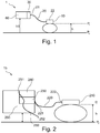
- Fig. 1 shows a schematic block diagram of a sensor apparatus 1 for cardio pulmonary resuscitation according to a first aspect of the invention.
- the sensor apparatus 1 comprises a liquid filled lumen 20, having a first fixed lumen end 21 and a first movable lumen end 22, and a pressure transducer 30.
- the first fixed lumen end 21 is attached to the pressure transducer 30.
- the first movable lumen end 22 comprises fixation means, for fixation to a movable element 10.
- the movable element 10 is a contact pad 10 for performing cardiopulmonary resuscitation (CPR) on a patient.
- the contact pad 10 may be a contact pad of an automated CPR device, or a pad designed for helping a rescuer performing CPR.
- the liquid filled lumen 20 may also be attached directly on a patient's chest on which CPR is performed.
- the first movable lumen end 22 is therefore moving with the chest compressions, between a first position, corresponding to a rest position Pr of the chest, and a second position, corresponding to a compressed position Pc of the chest.
- the compression depth is defined by a height h between the first and second positions.
- the pressure transducer 30 in the embodiment of Fig. 1 is mounted on a patient monitor 60, at a fixed (non-moving) position.
- the pressure transducer 30 is adapted to measure the compression depth by measuring the change in hydrostatic pressure in the lumen during movement of the first movable lumen end 22 of between the first and second positions. With each compression, the pressure transducer 30 is fixed whilst the first movable lumen end 22 moves. The change in hydrostatic liquid pressure is proportional to the height h between the rest position Pr and the compressed position Pc, hence proportional to the compression depth.
- the compression depth is directly related to the measured pressure difference.
- the compression depth is obtained by subtracting the two pressures measured between the rest position and the compressed position of the first movable lumen end.
- the sensor reference pressure is constant and sensor position is not varied, also changes in rest position can be monitored.
- the absolute compression depth can be measured during the course of a resuscitation.
- the pressure transducer 30 in the embodiment of Fig. 1 is mounted on a patient monitor.
- the pressure transducer 30 may be mounted elsewhere, as long as the pressure transducer 30 is positioned at a fixed location.
- the pressure transducer 30 can be any kind of pressure transducer, e.g. a strain gage transducer, a tip pressure transducer, etc.
- Chest molding relates to the fact that a patient's chest might not recoil to its original position during the course of a CPR event. Because of chest molding, the absolute position of the chest changes during CPR, which in its turn affects the compression depth.
- the incomplete recoil can be a short term or a long term effect.
- the short term effect is caused by giving compressions faster than the ability of the chest to recoil.
- the long term effect is caused by the diminishing elasticity of the human chest. When the chest is compressed for a long time, the elasticity is reduced, causing the chest to recoil to a lower position than originally planned. This is comparable to stretching a rubber band (or slow foam mattress). If this is done a few times, the band will not get back to its original state, but will be stretched somewhat in its relaxed position.
- the pressure signal from the pressure transducer 30 has an alternating component and continuous component.
- the continuous component of the pressure transducer 30 can provide information on the chest thickness and also incorporates fixed height difference between the sensor and the patient. In the course of resuscitation, the chest thickness may not recover entirely due to chest molding. The continuous component of the difference therefore drifts, between an initial level to a drift level. If the chest does not recoil completely - or in other words if the rest position changes over the course of the resuscitation, there will be a change in the DC level of the pressure. The change in DC level corresponds with change in rest level when all other components of the signal do not vary. The instantaneous compression depth is measured by the alternating component of the pressure signal. Note that when the height of the bed is changed with respect to the sensor the DC pressure component will also change.
- Fig. 2 shows a schematic block diagram of a sensor apparatus 1b for cardio pulmonary resuscitation according to a first aspect of the invention.
- the sensor apparatus 1b comprises a first liquid filled lumen 220 and a first pressure transducer 230.
- the first liquid filled lumen 220 has a first fixed lumen end 221 and a first movable lumen end 222.
- the first fixed lumen end 221 is attached to the first pressure transducer 230.
- the first movable lumen end 222 comprises fixation means, for fixation to a movable element.
- the first movable lumen end 222 is attached to a contact pad 210 for performing CPR.
- the contact pad 210 may be a contact pad of an automated CPR device, or a pad designed for helping a rescuer performing CPR.
- the first movable lumen end 222 may also be attached directly on a patient's chest on which CPR is performed.
- the first movable lumen end 222 is therefore movable between a first position, corresponding to a rest position Pr of the chest, and a second position, corresponding to a compressed position Pc of the chest, whilst the first fixed lumen end 221 is fixed.
- a height h between the first and second position defines the compression depth, for a given compression.
- the first pressure transducer 230 is adapted to measure the compression depth by measuring the change in liquid pressure in the first lumen 220 during movement of the first movable lumen end 222 between the first position and the second position.
- the first pressure transducer 230 in the embodiment of Fig. 2 is mounted on a patient monitor 260.
- the first pressure transducer 30 may be mounted elsewhere, as long as the pressure transducer 230 is positioned fixedly at an absolute height level.
- the sensor apparatus 1b comprises a second pressure transducer 240 and a second liquid filled lumen 250 having a second fixed lumen end 251 and a second movable lumen end 252.
- the second fixed lumen end 251 in the example of Fig. 2 , is fixed to the second pressure transducer 240 and the second movable lumen end 252 is fixed at a non moving location near the patient.
- the second pressure transducer 240 is adapted to form a reference pressure sensor, in order to measure external deviations such as changes of the atmospheric pressure and level changes of the monitoring apparatus.
- the second pressure transducer 240 in the example of Fig. 2 is mounted on a patient monitor, close to the first pressure transducer 230.
- the second pressure transducer 240 may be mounted elsewhere, as long as the pressure transducer is positioned fixedly at an absolute height level.
- the second movable lumen end can be positioned below the patient's chest, in a similar position as is shown on Fig. 3 .
- the first and second pressure transducers 230, 240 can be one of a strain gage transducer a tip pressure transducer, or any other pressure transducer. Note that by using two different sensors drift in the signals poses a challenge.
- Fig. 3 shows a schematic block diagram of a sensor apparatus 1c for cardio pulmonary resuscitation according to another aspect of the invention.
- the sensor apparatus 1c comprises a first liquid filled lumen 320 and a first pressure transducer 330.
- the first liquid filled lumen 320 has a first fixed lumen end 321 and a first movable lumen end 322.
- the first fixed lumen end 321 is attached to the first pressure transducer 330.
- the first movable lumen end 322 comprises fixation means, for attachment to a movable element 310.
- the first movable lumen end 322 is attached to a contact pad 310, similarly to the embodiments of Figs. 1 and 2 .
- the first movable lumen end 322 is therefore movable between a first position, corresponding to a rest position Pr of the chest, and a second position, corresponding to a compressed position Pc of the chest.
- a height h between the first and second positions defines the compression depth, for a given compression.
- the first pressure transducer 330 is adapted to measure the compression depth by measuring a liquid pressure change in the first liquid filled lumen 320 during movement of the first movable lumen end 322 between the first position and the second position.
- the first pressure transducer 330 in the embodiment of Fig. 3 is mounted on a patient monitor 360.
- the first pressure transducer 330 may be mounted elsewhere, as long as the pressure transducer is positioned fixedly at an absolute height level.
- the sensor apparatus 1c comprises a second pressure transducer 340, and a second liquid filled lumen 350 having a second fixed lumen end 351 and a second movable lumen end 352.
- the second fixed lumen end 351 in the example of Fig. 3 , is fixed to the second pressure transducer 340 and the second movable lumen end 352 is fixed under the patient, below the patient's chest, preferably on the mattress 380 where the patient is lying.
- the second pressure transducer 340 is adapted to form a reference pressure sensor, in order to measure external deviations such as changes of the mattress height in the course of the resuscitation, the mattress being a compliant surface. Because of the chest compressions, both the patient and the compliant surface are compressed on the same time.
- the second movable lumen end 352 is therefore movable between a third position, corresponding to a rest position Prm of the mattress, and a fourth position, corresponding to a compressed position Pcm of the mattress.
- a height hm between the third and fourth positions defines the change in the reference position, for a given compression.
- the second pressure transducer 340 is adapted to measure the mattress compression depth by measuring a change in liquid pressure in the second liquid filled lumen 350 during movement of the second movable lumen end 352 between the third and fourth positions.
- differential pressure measurement can be achieved, using a substractor 390 to derive the resulting pressure as the difference between the pressure measured by the first pressure transducer and the pressure measured by the second pressure transducer.
- both the chest thickness and the real compression depth can be measured, as explained with reference to Figs. 5A to 5C .
- the absolute position of the first movable lumen end, hence of the compression pad, can be obtained.
- Fig. 4 shows a schematic block diagram of a sensor apparatus 1d for cardio pulmonary resuscitation according to another aspect of the invention.
- the sensor apparatus 1d of Fig. 4 mainly differs from the sensor apparatus 1c of Fig. 3 in that the apparatus uses a differential pressure sensor with only one transducer.
- the sensor apparatus 1d comprises a single differential pressure transducer 430, together with two lumens 420, 450.
- the first liquid filled lumen 420 has a first fixed lumen end 421 and a first movable lumen end 422.
- the first fixed lumen end 421 is attached to the pressure transducer 430.
- the first movable lumen end 422 comprises fixation means, for attachment to a movable element 310, and in particular to a contact pad 410, similarly to the embodiments of Figs. 1 and 3 .
- the first movable lumen end 422 is therefore movable between a first position, corresponding to a rest position Pr of the chest, and a second position, corresponding to a compressed position Pc of the chest.
- the second liquid filled lumen 450 has a second fixed lumen end 451 and a second movable lumen end 452.
- the second fixed lumen end 451 is fixed to the single differential pressure transducer 440 and the second movable lumen end 452 is fixed under the patient, below the patient's chest, preferably on the mattress 480 where the patient is lying.
- the second movable lumen end 352 is therefore movable between a third position, corresponding to a rest position Prm of the mattress, and a fourth position, corresponding to a compressed position Pcm of the mattress.
- a height hm between the third and fourth positions defines the change in the reference position, for a given compression.
- a change in liquid pressure in the second liquid filled lumen 350 during movement of the second movable lumen end 352 between the third and fourth positions gives information on the mattress compression depth.
- Differential pressure measurement can be achieved by the single pressure transducer which is adapted to directly obtain the differential pressure resulting from the changes measured in the first lumen and the changes measured in the second lumen.
- both the chest thickness and the real compression depth can be measured, similarly to the system described with reference to Fig. 3 .
- the absolute position of the first movable lumen end, hence of the compression pad can be obtained.
- Fig. 5A is a graphical representation of the pressure signal S1 from the first pressure transducer 330
- Fig. 5B is a graphical representation of the pressure signal S2 from the second pressure transducer 340
- Fig. 5C is a graphical representation of the differential pressure Sd between the pressure measured by the first pressure transducer and the pressure measured by the second pressure transducer measured over time, in a course of a resuscitation, with the sensors of Fig. 3 .
- the differential continuous component 3000 can change between an initial level 3001 to a drift level 3002.
- the initial level 3001 provides information on the chest thickness and the difference between the initial level 3001 and the drift level 3002 of the differential continuous component 3000 between transducer 330 and 340 gives information on the chest molding.
- the alternating component 3500 of the differential pressure Sd provides information on the chest compression depth.
- the information on the chest thickness may be used in order to tune the CPR performance to a specific person, whereby persons of different morphology may require different compression depths for a successful CPR.
- chest thickness measurement is achieved with embodiments wherein two lumens are used, e.g. in the example of Fig. 3 where the sensor apparatus comprises two transducers associated with two lumens or in the example of Fig. 4 wherein the sensor apparatus comprises one transducer associated with two lumens, the second movable end being below the patient. Further, measuring chest molding is achieved with a sensor apparatus comprising one or more transducer together with one or more lumen.
- Fig. 6 shows a method of measuring a compression depth, with reference to Figs. 3 and 4 .
- the first pressure transducer 330 which is attached to the monitor 360, measures a liquid pressure in the first liquid filled lumen 320.
- the first fixed lumen end 321 is attached to the first pressure transducer 330 and the first movable lumen end 322 is attached to the compression pad and is therefore movable between a first position and a second position, wherein a distance between the first and second position corresponds to the first compression depth.
- a second step S2 the first compression depth is derived, by obtaining the pressure corresponding to the measured liquid pressure.
- the second fixed lumen end 351 is attached to the second pressure transducer 340 and the second movable lumen end 352 is attached to the mattress below the patient's chest.
- the second movable lumen end 352 is therefore movable between a third position and a fourth position, during movement of the second movable lumen end between the third and the fourth positions, corresponding to a moving height.
- the second pressure transducer 340 therefore measures a pressure corresponding to a moving mattress height by measuring a liquid pressure in lumen 350.
- a difference between the first compression depth and the moving mattress height is derived.
- the difference is shown on Fig. 5c , with the alternating component 3500.
- This alternating component provides information on the absolute chest compression depth.
- the initial continuous component 3001 provides information on the chest thickness and the drift component 3002 of the difference between transducer 330 and 340 gives information on chest molding.
- the position of the first movable lumen end 321 and/or of the second movable lumen end 351 are calibrated before a first compression.
- the calibration corresponds to the setting of a zero level, at the start of the resuscitation.
- the calibration may be performed once. Alternately, the calibration may be triggered on a signal such as a force sensor signal.
- the compression sensor can be used not only to measure a compression depth but also to derive an absolute position of the first movable lumen end 322 and/or of the second movable lumen end 352. If the first movable lumen end 322 and/or the second movable lumen end 352 is fixed on a compression pad, an absolute position of the compression pad can be obtained.
Landscapes
- Health & Medical Sciences (AREA)
- Heart & Thoracic Surgery (AREA)
- Life Sciences & Earth Sciences (AREA)
- Cardiology (AREA)
- Veterinary Medicine (AREA)
- Public Health (AREA)
- General Health & Medical Sciences (AREA)
- Animal Behavior & Ethology (AREA)
- Pain & Pain Management (AREA)
- Rehabilitation Therapy (AREA)
- Physical Education & Sports Medicine (AREA)
- Epidemiology (AREA)
- Pulmonology (AREA)
- Emergency Medicine (AREA)
- Biophysics (AREA)
- Oral & Maxillofacial Surgery (AREA)
- Physics & Mathematics (AREA)
- Dentistry (AREA)
- Pathology (AREA)
- Engineering & Computer Science (AREA)
- Biomedical Technology (AREA)
- Medical Informatics (AREA)
- Molecular Biology (AREA)
- Surgery (AREA)
- Percussion Or Vibration Massage (AREA)
- Measurement Of The Respiration, Hearing Ability, Form, And Blood Characteristics Of Living Organisms (AREA)
Claims (7)
- Herz-Lungen-Wiederbelebungsvorrichtung mit einem Kompressionstiefe-Sensor (1, 1b, 1c, 1d) zum Messen einer Kompressionstiefe einer Patientenbrust während der Herz-Lungen-Wiederbelebung, wobei der Sensor umfassteinen ersten Druckwandler (30, 230, 330, 430), der an einem festen Element (60, 260, 360, 460) angebracht werden kann;ein erstes flüssigkeitsgefülltes Lumen (20, 220, 320, 420) mit einem ersten festen Lumenende (21, 221, 321, 421), das an dem Druckwandler angebracht werden kann, und einem ersten beweglichen Lumenende (22, 222, 322, 422) das zwischen einer ersten Position (Pr) und einer zweiten Position (Pc) beweglich ist, wobei ein Abstand zwischen der ersten und zweiten Position die Kompressionstiefe (h) definiert,wobei der erste Druckwandler angepasst ist, um die Kompressionstiefe durch Messen einer Änderung des hydrostatischen Flüssigkeitsdrucks im Lumen während der Bewegung des ersten beweglichen Lumenendes zwischen der ersten Position und der zweiten Position zu messen.
- Kardio-Lungen-Wiederbelebungsvorrichtung nach Anspruch 1, wobei das erste bewegliche Lumenende Fixierungsmittel zur Befestigung an einem ersten beweglichen Element (10, 210, 310, 410) umfasst, wobei das erste bewegliche Element ein Kompressionskissen ist.
- Herz-Lungen-Wiederbelebungsvorrichtung nach Anspruch 1, wobei die Vorrichtung zum Ableiten einer Differenz zwischen der Kompressionstiefe (h) und einer Bewegungshöhe (hm) des Patienten während der Herz-Lungen-Wiederbelebung dient, wobei die Vorrichtung umfassteinen zweiten Druckwandler (240, 340), der an dem festen Element anbringbar ist,ein zweites flüssigkeitsgefülltes Lumen (250, 350) mit einem zweiten festen Lumenende (251, 351), das an dem zweiten Druckwandler angebracht werden kann, und einem zweiten beweglichen Lumenende (252, 352) das zwischen einer dritten Position (Prm) und einer vierten Position (Pcm) beweglich ist, wobei ein Abstand zwischen der dritten und vierten Position die Bewegungshöhe definiert,
wobei der zweite Druckwandler angepasst ist, um die Bewegungshöhe zu messen, durch Messung des Flüssigkeitsdrucks in dem zweiten Lumen während der Bewegung des zweiten beweglichen Lumenendes zwischen der dritten und der vierten Position,ein Subtrahierer zum Ableiten einer Differenz zwischen der Kompressionstiefe und der Bewegungshöhe. - Herz-Lungen-Wiederbelebungsvorrichtung nach Anspruch 3, wobei das zweite bewegliche Lumenende zweite Fixierungsmittel zur Fixierung auf einer Oberfläche umfasst, auf der der Patient liegt.
- Herz-Lungen-Wiederbelebungsvorrichtung nach Anspruch 3 oder 4, wobei der erste Druckwandler und der zweite Druckwandler einer eines Dehnungsmesswandlers oder eines Spitzendruckwandlers sind.
- Herz-Lungen-Wiederbelebungsvorrichtung nach Anspruch 1, wobei die Vorrichtung zum Messen einer Bewegungshöhe (hm) des Patienten während der Herz-Lungen-Wiederbelebung dient, wobei die Vorrichtung ferner umfasst:
ein zweites flüssigkeitsgefülltes Lumen (450) mit einem zweiten festen Lumenende (451), das an dem ersten Druckwandler angebracht werden kann, und einem zweiten beweglichen Lumenende (452), das zwischen einer dritten Position (Prm) und einer vierten Position (Pcm) beweglich ist, wobei einen Abstand zwischen der dritten und vierten Position die Bewegungshöhe definiert, wobei der erste Druckwandler ein Differenzdruckwandler ist, der zum Messen der Bewegungshöhe zwischen dem ersten und zweiten beweglichen Ende durch Messen des Differenzflüssigkeitsdrucks zwischen dem ersten und dem zweiten Lumen während der Bewegung des ersten und zweiten beweglichen Lumenendes geeignet ist, wobei der erste Druckwandler angepasst ist, um einen Differenzdruck abzuleiten, der sich aus den gemessenen Flüssigkeitsdrücken im ersten und zweiten Lumen ergibt. - Herz-Lungen-Wiederbelebungsvorrichtung nach Anspruch 2, wobei der Kompressionstiefe-Sensor angepasst ist, um die absolute Positionsdifferenz des Kompressionskissens in Bezug auf die Anfangsposition des Sensors abzuleiten.
Applications Claiming Priority (2)
| Application Number | Priority Date | Filing Date | Title |
|---|---|---|---|
| US201261641351P | 2012-05-02 | 2012-05-02 | |
| PCT/IB2013/053437 WO2013164768A1 (en) | 2012-05-02 | 2013-05-01 | Physiological sensor |
Publications (2)
| Publication Number | Publication Date |
|---|---|
| EP2844211A1 EP2844211A1 (de) | 2015-03-11 |
| EP2844211B1 true EP2844211B1 (de) | 2020-07-08 |
Family
ID=48614087
Family Applications (1)
| Application Number | Title | Priority Date | Filing Date |
|---|---|---|---|
| EP13728533.4A Active EP2844211B1 (de) | 2012-05-02 | 2013-05-01 | Physiologischer sensor |
Country Status (5)
| Country | Link |
|---|---|
| US (1) | US9554730B2 (de) |
| EP (1) | EP2844211B1 (de) |
| JP (1) | JP6401149B2 (de) |
| CN (1) | CN104271103B (de) |
| WO (1) | WO2013164768A1 (de) |
Families Citing this family (4)
| Publication number | Priority date | Publication date | Assignee | Title |
|---|---|---|---|---|
| US11058602B2 (en) | 2015-09-21 | 2021-07-13 | Zoll Medical Corporation | Chest compliance directed chest compressions |
| WO2017162616A1 (en) * | 2016-03-23 | 2017-09-28 | Koninklijke Philips N.V. | Blood pressure monitor |
| GB2593885A (en) * | 2020-04-03 | 2021-10-13 | Heartsine Tech Limited | Defibrillator assessing chest recoil in cardio pulmonary resuscitation |
| CN113768774B (zh) * | 2021-09-26 | 2022-07-29 | 河南科技大学第一附属医院 | 心肺复苏辅助装置 |
Citations (1)
| Publication number | Priority date | Publication date | Assignee | Title |
|---|---|---|---|---|
| US20040002667A1 (en) * | 2001-05-25 | 2004-01-01 | Revivant Corporation | CPR device with pressure bladder feedback |
Family Cites Families (11)
| Publication number | Priority date | Publication date | Assignee | Title |
|---|---|---|---|---|
| US4077400A (en) | 1975-01-17 | 1978-03-07 | Roy Major Harrigan | External cardiac resuscitation aid |
| IL138040A0 (en) | 2000-08-23 | 2001-10-31 | Cpr Devices Ltd | Monitored cardiopulmonary resuscitation device |
| FR2842900A1 (fr) | 2002-07-26 | 2004-01-30 | Ffb | Pige de mesure de hauteur |
| US6827695B2 (en) | 2002-10-25 | 2004-12-07 | Revivant Corporation | Method of determining depth of compressions during cardio-pulmonary resuscitation |
| GB2446605A (en) | 2007-02-15 | 2008-08-20 | Laerdal Medical As | Determining CPR chest compression depth |
| CN102164573B (zh) | 2008-07-23 | 2015-12-02 | 菲希欧控制加拿大销售有限公司 | 用于在心肺复苏期间测量按压参数的cpr辅助装置 |
| US20100040217A1 (en) | 2008-08-18 | 2010-02-18 | Sony Ericsson Mobile Communications Ab | System and method for identifying an active participant in a multiple user communication session |
| CN102341085B (zh) | 2009-03-06 | 2014-02-12 | 阿特雷奥医疗公司 | 对在表面上的cpr的按压参数的测量 |
| WO2011011633A2 (en) | 2009-07-22 | 2011-01-27 | Atreo Medical, Inc. | Optical techniques for the measurement of chest compression depth and other parameters during cpr |
| NO20093315A1 (no) | 2009-11-11 | 2011-05-12 | Laerdal Medical As | Metode og system for a male parametre for brystkasse, spesielt ved hjertelungeredning |
| US9486390B2 (en) * | 2010-09-30 | 2016-11-08 | Physio-Control, Inc. | Reference sensor for CPR feedback device |
-
2013
- 2013-05-01 CN CN201380023048.8A patent/CN104271103B/zh not_active Expired - Fee Related
- 2013-05-01 WO PCT/IB2013/053437 patent/WO2013164768A1/en active Application Filing
- 2013-05-01 US US14/394,937 patent/US9554730B2/en active Active
- 2013-05-01 EP EP13728533.4A patent/EP2844211B1/de active Active
- 2013-05-01 JP JP2015509546A patent/JP6401149B2/ja not_active Expired - Fee Related
Patent Citations (1)
| Publication number | Priority date | Publication date | Assignee | Title |
|---|---|---|---|---|
| US20040002667A1 (en) * | 2001-05-25 | 2004-01-01 | Revivant Corporation | CPR device with pressure bladder feedback |
Also Published As
| Publication number | Publication date |
|---|---|
| EP2844211A1 (de) | 2015-03-11 |
| US20150094617A1 (en) | 2015-04-02 |
| US9554730B2 (en) | 2017-01-31 |
| JP2015523870A (ja) | 2015-08-20 |
| CN104271103A (zh) | 2015-01-07 |
| JP6401149B2 (ja) | 2018-10-03 |
| WO2013164768A1 (en) | 2013-11-07 |
| CN104271103B (zh) | 2017-03-08 |
Similar Documents
| Publication | Publication Date | Title |
|---|---|---|
| EP2844211B1 (de) | Physiologischer sensor | |
| US10952925B2 (en) | System and method for determining depth of chest compressions | |
| US10617599B2 (en) | System for determining depth of chest compressions during CPR | |
| US9649251B2 (en) | Method and system for measuring chest parameters, especially during CPR | |
| US20160338602A1 (en) | Device and method for measuring arterial signals | |
| EP3430980A1 (de) | Vorrichtung zur messung eines physiologischen parameters mit einem am körper tragbaren sensor | |
| EP3003133A1 (de) | Blutdruckmessvorrichtung | |
| KR101347413B1 (ko) | Cpr에서 환자 흉부 압박 깊이 모니터링 시스템 및 방법 | |
| CN104274172A (zh) | 一种胸外按压深度的监测方法、系统和除颤仪 | |
| JP6568236B2 (ja) | コア安定化運動管理システム | |
| WO2007112527A3 (en) | Devices constructive arrangement and methods applied to thoraxic cirtometry | |
| Song et al. | The development of feedback monitoring device for CPR | |
| JP2015523870A5 (de) | ||
| WO2017029398A1 (en) | Ventilation measurements | |
| Gohier et al. | Development of a smart backboard system for real-time feedback during CPR chest compression on a soft back support surface | |
| EP3547903B1 (de) | Kompressionstiefenberechnungsvorrichtung | |
| US20220110827A1 (en) | Systems and Methods for Determining Compression Depth and Providing Feedback During Active Compression Decompressions | |
| US11129769B2 (en) | Method for measuring strokes of CPR and system using the same | |
| AU2016201047A1 (en) | Method of determining depth of compressions during cardio-pulmonary resuscitation | |
| CN117562799A (zh) | Cpr采集设备及应用于cpr采集设备的按压深度测量方法 |
Legal Events
| Date | Code | Title | Description |
|---|---|---|---|
| PUAI | Public reference made under article 153(3) epc to a published international application that has entered the european phase |
Free format text: ORIGINAL CODE: 0009012 |
|
| 17P | Request for examination filed |
Effective date: 20141202 |
|
| AK | Designated contracting states |
Kind code of ref document: A1 Designated state(s): AL AT BE BG CH CY CZ DE DK EE ES FI FR GB GR HR HU IE IS IT LI LT LU LV MC MK MT NL NO PL PT RO RS SE SI SK SM TR |
|
| AX | Request for extension of the european patent |
Extension state: BA ME |
|
| DAX | Request for extension of the european patent (deleted) | ||
| STAA | Information on the status of an ep patent application or granted ep patent |
Free format text: STATUS: EXAMINATION IS IN PROGRESS |
|
| 17Q | First examination report despatched |
Effective date: 20161028 |
|
| GRAP | Despatch of communication of intention to grant a patent |
Free format text: ORIGINAL CODE: EPIDOSNIGR1 |
|
| STAA | Information on the status of an ep patent application or granted ep patent |
Free format text: STATUS: GRANT OF PATENT IS INTENDED |
|
| INTG | Intention to grant announced |
Effective date: 20200108 |
|
| RAP1 | Party data changed (applicant data changed or rights of an application transferred) |
Owner name: KONINKLIJKE PHILIPS N.V. |
|
| GRAS | Grant fee paid |
Free format text: ORIGINAL CODE: EPIDOSNIGR3 |
|
| GRAA | (expected) grant |
Free format text: ORIGINAL CODE: 0009210 |
|
| STAA | Information on the status of an ep patent application or granted ep patent |
Free format text: STATUS: THE PATENT HAS BEEN GRANTED |
|
| AK | Designated contracting states |
Kind code of ref document: B1 Designated state(s): AL AT BE BG CH CY CZ DE DK EE ES FI FR GB GR HR HU IE IS IT LI LT LU LV MC MK MT NL NO PL PT RO RS SE SI SK SM TR |
|
| REG | Reference to a national code |
Ref country code: GB Ref legal event code: FG4D |
|
| REG | Reference to a national code |
Ref country code: AT Ref legal event code: REF Ref document number: 1287674 Country of ref document: AT Kind code of ref document: T Effective date: 20200715 Ref country code: CH Ref legal event code: EP |
|
| REG | Reference to a national code |
Ref country code: DE Ref legal event code: R096 Ref document number: 602013070501 Country of ref document: DE |
|
| REG | Reference to a national code |
Ref country code: IE Ref legal event code: FG4D |
|
| REG | Reference to a national code |
Ref country code: LT Ref legal event code: MG4D |
|
| REG | Reference to a national code |
Ref country code: AT Ref legal event code: MK05 Ref document number: 1287674 Country of ref document: AT Kind code of ref document: T Effective date: 20200708 |
|
| REG | Reference to a national code |
Ref country code: NL Ref legal event code: MP Effective date: 20200708 |
|
| PG25 | Lapsed in a contracting state [announced via postgrant information from national office to epo] |
Ref country code: FI Free format text: LAPSE BECAUSE OF FAILURE TO SUBMIT A TRANSLATION OF THE DESCRIPTION OR TO PAY THE FEE WITHIN THE PRESCRIBED TIME-LIMIT Effective date: 20200708 Ref country code: GR Free format text: LAPSE BECAUSE OF FAILURE TO SUBMIT A TRANSLATION OF THE DESCRIPTION OR TO PAY THE FEE WITHIN THE PRESCRIBED TIME-LIMIT Effective date: 20201009 Ref country code: SE Free format text: LAPSE BECAUSE OF FAILURE TO SUBMIT A TRANSLATION OF THE DESCRIPTION OR TO PAY THE FEE WITHIN THE PRESCRIBED TIME-LIMIT Effective date: 20200708 Ref country code: NO Free format text: LAPSE BECAUSE OF FAILURE TO SUBMIT A TRANSLATION OF THE DESCRIPTION OR TO PAY THE FEE WITHIN THE PRESCRIBED TIME-LIMIT Effective date: 20201008 Ref country code: ES Free format text: LAPSE BECAUSE OF FAILURE TO SUBMIT A TRANSLATION OF THE DESCRIPTION OR TO PAY THE FEE WITHIN THE PRESCRIBED TIME-LIMIT Effective date: 20200708 Ref country code: BG Free format text: LAPSE BECAUSE OF FAILURE TO SUBMIT A TRANSLATION OF THE DESCRIPTION OR TO PAY THE FEE WITHIN THE PRESCRIBED TIME-LIMIT Effective date: 20201008 Ref country code: PT Free format text: LAPSE BECAUSE OF FAILURE TO SUBMIT A TRANSLATION OF THE DESCRIPTION OR TO PAY THE FEE WITHIN THE PRESCRIBED TIME-LIMIT Effective date: 20201109 Ref country code: AT Free format text: LAPSE BECAUSE OF FAILURE TO SUBMIT A TRANSLATION OF THE DESCRIPTION OR TO PAY THE FEE WITHIN THE PRESCRIBED TIME-LIMIT Effective date: 20200708 Ref country code: HR Free format text: LAPSE BECAUSE OF FAILURE TO SUBMIT A TRANSLATION OF THE DESCRIPTION OR TO PAY THE FEE WITHIN THE PRESCRIBED TIME-LIMIT Effective date: 20200708 Ref country code: LT Free format text: LAPSE BECAUSE OF FAILURE TO SUBMIT A TRANSLATION OF THE DESCRIPTION OR TO PAY THE FEE WITHIN THE PRESCRIBED TIME-LIMIT Effective date: 20200708 |
|
| PG25 | Lapsed in a contracting state [announced via postgrant information from national office to epo] |
Ref country code: IS Free format text: LAPSE BECAUSE OF FAILURE TO SUBMIT A TRANSLATION OF THE DESCRIPTION OR TO PAY THE FEE WITHIN THE PRESCRIBED TIME-LIMIT Effective date: 20201108 Ref country code: LV Free format text: LAPSE BECAUSE OF FAILURE TO SUBMIT A TRANSLATION OF THE DESCRIPTION OR TO PAY THE FEE WITHIN THE PRESCRIBED TIME-LIMIT Effective date: 20200708 Ref country code: RS Free format text: LAPSE BECAUSE OF FAILURE TO SUBMIT A TRANSLATION OF THE DESCRIPTION OR TO PAY THE FEE WITHIN THE PRESCRIBED TIME-LIMIT Effective date: 20200708 Ref country code: PL Free format text: LAPSE BECAUSE OF FAILURE TO SUBMIT A TRANSLATION OF THE DESCRIPTION OR TO PAY THE FEE WITHIN THE PRESCRIBED TIME-LIMIT Effective date: 20200708 |
|
| PG25 | Lapsed in a contracting state [announced via postgrant information from national office to epo] |
Ref country code: NL Free format text: LAPSE BECAUSE OF FAILURE TO SUBMIT A TRANSLATION OF THE DESCRIPTION OR TO PAY THE FEE WITHIN THE PRESCRIBED TIME-LIMIT Effective date: 20200708 |
|
| REG | Reference to a national code |
Ref country code: DE Ref legal event code: R097 Ref document number: 602013070501 Country of ref document: DE |
|
| PG25 | Lapsed in a contracting state [announced via postgrant information from national office to epo] |
Ref country code: DK Free format text: LAPSE BECAUSE OF FAILURE TO SUBMIT A TRANSLATION OF THE DESCRIPTION OR TO PAY THE FEE WITHIN THE PRESCRIBED TIME-LIMIT Effective date: 20200708 Ref country code: EE Free format text: LAPSE BECAUSE OF FAILURE TO SUBMIT A TRANSLATION OF THE DESCRIPTION OR TO PAY THE FEE WITHIN THE PRESCRIBED TIME-LIMIT Effective date: 20200708 Ref country code: CZ Free format text: LAPSE BECAUSE OF FAILURE TO SUBMIT A TRANSLATION OF THE DESCRIPTION OR TO PAY THE FEE WITHIN THE PRESCRIBED TIME-LIMIT Effective date: 20200708 Ref country code: IT Free format text: LAPSE BECAUSE OF FAILURE TO SUBMIT A TRANSLATION OF THE DESCRIPTION OR TO PAY THE FEE WITHIN THE PRESCRIBED TIME-LIMIT Effective date: 20200708 Ref country code: SM Free format text: LAPSE BECAUSE OF FAILURE TO SUBMIT A TRANSLATION OF THE DESCRIPTION OR TO PAY THE FEE WITHIN THE PRESCRIBED TIME-LIMIT Effective date: 20200708 Ref country code: RO Free format text: LAPSE BECAUSE OF FAILURE TO SUBMIT A TRANSLATION OF THE DESCRIPTION OR TO PAY THE FEE WITHIN THE PRESCRIBED TIME-LIMIT Effective date: 20200708 |
|
| PLBE | No opposition filed within time limit |
Free format text: ORIGINAL CODE: 0009261 |
|
| STAA | Information on the status of an ep patent application or granted ep patent |
Free format text: STATUS: NO OPPOSITION FILED WITHIN TIME LIMIT |
|
| PG25 | Lapsed in a contracting state [announced via postgrant information from national office to epo] |
Ref country code: AL Free format text: LAPSE BECAUSE OF FAILURE TO SUBMIT A TRANSLATION OF THE DESCRIPTION OR TO PAY THE FEE WITHIN THE PRESCRIBED TIME-LIMIT Effective date: 20200708 |
|
| 26N | No opposition filed |
Effective date: 20210409 |
|
| PG25 | Lapsed in a contracting state [announced via postgrant information from national office to epo] |
Ref country code: SK Free format text: LAPSE BECAUSE OF FAILURE TO SUBMIT A TRANSLATION OF THE DESCRIPTION OR TO PAY THE FEE WITHIN THE PRESCRIBED TIME-LIMIT Effective date: 20200708 |
|
| PGFP | Annual fee paid to national office [announced via postgrant information from national office to epo] |
Ref country code: DE Payment date: 20210527 Year of fee payment: 9 |
|
| PG25 | Lapsed in a contracting state [announced via postgrant information from national office to epo] |
Ref country code: SI Free format text: LAPSE BECAUSE OF FAILURE TO SUBMIT A TRANSLATION OF THE DESCRIPTION OR TO PAY THE FEE WITHIN THE PRESCRIBED TIME-LIMIT Effective date: 20200708 |
|
| REG | Reference to a national code |
Ref country code: CH Ref legal event code: PL |
|
| GBPC | Gb: european patent ceased through non-payment of renewal fee |
Effective date: 20210501 |
|
| PG25 | Lapsed in a contracting state [announced via postgrant information from national office to epo] |
Ref country code: CH Free format text: LAPSE BECAUSE OF NON-PAYMENT OF DUE FEES Effective date: 20210531 Ref country code: LU Free format text: LAPSE BECAUSE OF NON-PAYMENT OF DUE FEES Effective date: 20210501 Ref country code: MC Free format text: LAPSE BECAUSE OF FAILURE TO SUBMIT A TRANSLATION OF THE DESCRIPTION OR TO PAY THE FEE WITHIN THE PRESCRIBED TIME-LIMIT Effective date: 20200708 Ref country code: LI Free format text: LAPSE BECAUSE OF NON-PAYMENT OF DUE FEES Effective date: 20210531 |
|
| REG | Reference to a national code |
Ref country code: BE Ref legal event code: MM Effective date: 20210531 |
|
| PG25 | Lapsed in a contracting state [announced via postgrant information from national office to epo] |
Ref country code: IE Free format text: LAPSE BECAUSE OF NON-PAYMENT OF DUE FEES Effective date: 20210501 Ref country code: GB Free format text: LAPSE BECAUSE OF NON-PAYMENT OF DUE FEES Effective date: 20210501 |
|
| PG25 | Lapsed in a contracting state [announced via postgrant information from national office to epo] |
Ref country code: FR Free format text: LAPSE BECAUSE OF NON-PAYMENT OF DUE FEES Effective date: 20210531 |
|
| PG25 | Lapsed in a contracting state [announced via postgrant information from national office to epo] |
Ref country code: BE Free format text: LAPSE BECAUSE OF NON-PAYMENT OF DUE FEES Effective date: 20210531 |
|
| REG | Reference to a national code |
Ref country code: DE Ref legal event code: R119 Ref document number: 602013070501 Country of ref document: DE |
|
| PG25 | Lapsed in a contracting state [announced via postgrant information from national office to epo] |
Ref country code: HU Free format text: LAPSE BECAUSE OF FAILURE TO SUBMIT A TRANSLATION OF THE DESCRIPTION OR TO PAY THE FEE WITHIN THE PRESCRIBED TIME-LIMIT; INVALID AB INITIO Effective date: 20130501 Ref country code: DE Free format text: LAPSE BECAUSE OF NON-PAYMENT OF DUE FEES Effective date: 20221201 |
|
| PG25 | Lapsed in a contracting state [announced via postgrant information from national office to epo] |
Ref country code: CY Free format text: LAPSE BECAUSE OF FAILURE TO SUBMIT A TRANSLATION OF THE DESCRIPTION OR TO PAY THE FEE WITHIN THE PRESCRIBED TIME-LIMIT Effective date: 20200708 |
|
| PG25 | Lapsed in a contracting state [announced via postgrant information from national office to epo] |
Ref country code: MK Free format text: LAPSE BECAUSE OF FAILURE TO SUBMIT A TRANSLATION OF THE DESCRIPTION OR TO PAY THE FEE WITHIN THE PRESCRIBED TIME-LIMIT Effective date: 20200708 |