EP2844110B1 - Mechanism for collapsible bunk-beds - Google Patents
Mechanism for collapsible bunk-beds Download PDFInfo
- Publication number
- EP2844110B1 EP2844110B1 EP13707871.3A EP13707871A EP2844110B1 EP 2844110 B1 EP2844110 B1 EP 2844110B1 EP 13707871 A EP13707871 A EP 13707871A EP 2844110 B1 EP2844110 B1 EP 2844110B1
- Authority
- EP
- European Patent Office
- Prior art keywords
- bed frame
- upper bed
- base
- frame
- mechanism according
- Prior art date
- Legal status (The legal status is an assumption and is not a legal conclusion. Google has not performed a legal analysis and makes no representation as to the accuracy of the status listed.)
- Active
Links
Images


Classifications
-
- A—HUMAN NECESSITIES
- A47—FURNITURE; DOMESTIC ARTICLES OR APPLIANCES; COFFEE MILLS; SPICE MILLS; SUCTION CLEANERS IN GENERAL
- A47C—CHAIRS; SOFAS; BEDS
- A47C19/00—Bedsteads
- A47C19/20—Multi-stage bedsteads; Bedsteads stackable to multi-stage bedsteads
- A47C19/205—Multi-stage bedsteads; Bedsteads stackable to multi-stage bedsteads convertible, e.g. from single bed or sofa
Definitions
- the present invention relates to a mechanism for collapsible bunk-beds and to a sofa bed comprising such mechanism.
- lever systems there are those which, in order to achieve the closing motion of the bunk-bed, entail the rotation through 180° of the upper bed frame.
- the lever systems comprise pivoting axes that can move on a horizontal plane toward the inside of the mechanism.
- lever systems that can move horizontally toward the inside of the bunk-bed can entail problems of interference with the mattress of the lower bed frame.
- locking systems are provided which prevent the upper bed frame, when it is in the raised position, from returning to the lowered position or in any case from changing its own stable position for use.
- BE 472 181 A discloses a double ottoman with upper and lower ottomans connected into an open-out condition and adapted for a lifting motion to two lateral supporting frames each comprising a pair of arms arranged in scissors fashion and connected to the lower ottoman so that the upper surfaces of the two ottomans will be brought to the same height.
- the aim of the present invention is to overcome the drawbacks of the background art, by devising a mechanism for collapsible bunk-beds that is particularly sturdy and easy to move.
- an object of the invention is to provide a movement mechanism for collapsible bunk-beds that is not interposed between the upper and lower bed frames.
- a further object of the invention is to provide a mechanism for collapsible bunk-beds that does not entail a rotation of the upper bed frame.
- Another object of the invention is to provide a mechanism for collapsible bunk-beds that uses an extremely limited number of levers while maintaining high structural stability.
- a further object of the present invention is to devise a mechanism for collapsible bunk-beds that can be used to obtain a sofa bed.
- a further object of the present invention is to provide a safety mechanism for collapsible bunk-beds which allows the user to lock the upper bed frame in position.
- an object of the invention is to render the safety mechanism activatable compulsorily by the user in order to be able to use the bunk-bed.
- Another object of the invention is to provide a safety mechanism that forces the user to assemble at least one longitudinal safety barrier of the upper bed frame in order to be able to use the bunk-bed.
- Another object of the present invention is to provide a mechanism for collapsible bunk-beds that avoids the need to have a removable ladder.
- Another object of the invention is to provide a mechanism for collapsible bunk-beds that is highly reliable, relatively easy to provide and at competitive costs.
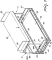
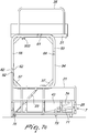
- a mechanism for collapsible bunk-beds comprises a base 2 that is substantially shaped like a parallelepiped and is provided at its opposite sides with lateral sides 21 that connect a front part 22 and a rear part 26, so as to form a containment seat for a lower bed frame 4.
- the lateral sides 21 are such as to protrude vertically with respect to said containment seat and to the surface of the lower bed frame, so that they can be used conveniently both as barriers for the lateral containment of the mattress 43 and as frames in order to obtain the armrests of a sofa bed that uses the mechanism 1.
- the front part 22 comprises at least one pair of resting elements 24, for example brackets that are welded onto the front part 22 and protrude toward the inside of the containment seat formed in the base 2.
- the resting elements 24 are adapted to support the lower bed frame 4 in its raised position and the upper bed frame 3 in its collapsed position.
- the lower bed frame 4 can be constituted by a pair of crossmembers 41 and a pair of longitudinal members 42, so as to define a frame that is adapted to support a mattress 43, for example by means of wood slats of a known type which are connected like a bridge between the longitudinal members 42.
- the mechanism 1 comprises an upper bed frame 3, which is also defined by a pair of crossmembers 31 and a pair of longitudinal members 32 so as to define a frame suitable to support a mattress 33, for example by means of wood slats of a known type which are connected like a bridge between the longitudinal members 32.
- a front safety barrier 34 can be provided on at least one longitudinal member 32 and is preferably fixed detachably to said longitudinal member 32 for example by means of handwheels. Additional safety barriers 35, which are not necessarily removable and are useful to prevent the sliding of the mattress 33 on the surface of the upper bed frame 3, can be present on the crossmembers 31.
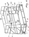
- the lateral sides 21 of the base 2 are connected to the crossmembers 31 of the upper bed frame by way of respective first lever systems 5, which are adapted to allow the movement of the upper bed frame 3 away and toward the base 2.
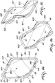
- Each one of the first lever systems 5 defines an articulated quadrilateral that lies on a plane that is substantially perpendicular to the plane of the upper bed frame 3.
- the articulated quadrilateral is preferably an articulated parallelogram 6, shown in broken lines in Figures 6a-6c , and has a hinge, obtained for example by means of a hinged joint 61, the pivoting axis of which coincides with the longitudinal axis of the upper bed frame 3 that passes substantially through the center of the crossmembers 31 of the upper bed frame 3.
- the articulated parallelogram 6 further has two additional hinges that are integral with the base 2 and are also obtained preferably by means of hinged joints 62 and 63.
- the fourth hinge of the articulated parallelogram 6, also preferably obtained by means of a hinged joint 64, is integral with the motion of the upper bed frame 3, and so is the hinged joint 61.
- a short side of the parallelogram 6 is defined between the joints in a fixed position with respect to the base 2, i.e., the joints 62 and 63, and is inclined with respect to the floor resting surface of the base 2 so as to define an acute angle toward the rear part 26 of the base 2, for example of approximately 60°.
- the joint 61 that is arranged on the upper bed frame 3 can approach the fixed joints 62 and 63, allowing the upper bed frame 3, in the collapsed position, to arrange itself substantially above the lower bed frame 4.
- the hinged joints 61, 62, 63 and 64 can be adapted to allow a mutual rotation of no more than approximately 90° between the levers that are connected thereto.
- Such levers are preferably four L-shaped levers 52-53 and 54-55 that are identical in pairs and are adapted to define a substantially rectangular shape and more preferably square shape when the upper bed frame 3 is in the fully raised position with respect to the base 2.
- a first L-shaped lever 52 is fixed rigidly to an inner side of the respective lateral side 21 of the base 2, and a second L-shaped lever 53 is fixed rigidly laterally to the upper bed frame 3, for example by a fixing angled element 533 that is fixed along the respective crossmember 31 so as to prevent relative rotation between the upper bed frame 3 and said second L-shaped lever 53.
- the L-shaped levers 52 and 53 are crossed by a diagonal of the substantially rectangular shape of the lever system 5, while the third L-shaped lever 54 and the fourth L-shaped lever 55 are crossed by the other diagonal of said substantially rectangular shape.
- the first and second L-shaped levers 52 and 53 each comprise two arms that are arranged at right angles to each other and have a substantially identical extension, 521-522 and 531-532 respectively, and are connected by a curved portion.
- the third and fourth L-shaped levers 54 and 55 also each comprise two arms 541-542 and 551-552 respectively, which are oriented at right angles to each other and have a substantially mutually identical extension that is greater than the extension of the arms 521-522 and 531-532 of the first and second L-shaped levers 52 and 53.
- the mutually pivoted arms are substantially perpendicular to each other when the upper bed frame 3 is in the collapsed position, as shown in Figure 6c , in which the first lever system 5 is interposed between the lateral side 21 of the base 2 and the crossmember 31.
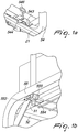
- the third L-shaped lever 54 advantageously comprises a locking element to prevent the movement of the first lever system 5.
- Such locking element can be obtained by means of a lock 543 on the arm 541, which is provided with a bolt 544, which can move between an extended position, in which the bolt of 544 abuts above the lateral side 21 of the base 2, and a retracted position, in which the bolt 544 does not protrude transversely from the third L-shaped lever 54 and allows its rotation with respect to the first L-shaped lever 52.
- the bolt 544 can be moved by means of a removable key 546.
- a further locking element 553 can be provided between the first lever systems 5 and the upper bed frame 3, for example in the form of a bar 554 that can slide in a fork-shaped bracket 555 that is fixed below the arm 551 of the fourth L-shaped lever 55 so as to engage detachably below the respective crossmember 31.
- the arm 541 may further be connected to a gas cylinder actuator 23, for example by means of a plate 545 in a position that is substantially intermediate to the arm 541.
- the gas cylinder actuator 23 is connected, at its other end, to the rear part 26 or to the side 21, preferably in a point that is substantially aligned vertically with the articulation 62 and is close to the resting surface of the base 2, so as to facilitate the opening and closing movements of the upper bed frame 3.
- the first lever systems 5 can be connected rigidly to each other by transverse reinforcement bars, for example by a reinforcement bar 56 that is welded between the fourth L-shaped levers 65 at the arms 552.
- the reinforcement bar 56 if welded proximate to the articulations 62, can constitute advantageously a supporting element for the cushions of the back of the sofa bed that uses the mechanism 1 according to the invention.
- Each one of the L-shaped levers 52, 53, 54, 55 may further have angular reinforcement elements 57 that are arranged in a bridge-like fashion between the respective arms.
- the lower bed frame 4 of the mechanism according to the invention can also be liftable with respect to the base 2 by means of second lever systems 71 and 75.
- first lower lever 71 that has an end that is pivoted on a substantially intermediate point of a crossmember 41 of the lower bed frame 4 and the other end pivoted on the front part 22 of the base 2, for example on a vertical extension 25 of the bracket that constitutes the resting element 24.
- the two first lower levers 71 can have a bracket 73 in a substantially intermediate position, on which a rod 72 for connecting the two first lower levers 71 is fixed and is arranged below the lower bed frame 4.
- the bracket 72 can be connected by means of a spring 74 to the front part 22 of the base 2, preferably at a higher level than the pivoting point of the lever 71 on the vertical extension 25 of the resting element 24, so that the spring 74 arranges itself substantially parallel to the crossmembers 41 of the lower bed frame 4 when said frame is in the raised position, shown in Figures 1 and 7a .
- the corner ends of the crossmembers 41 on the opposite side with respect to the front part 22 are instead connected to second lower levers 75, each pivoted between one of said corner ends or a bracket that is integral therewith and the rear part 26 of the base 2, for example in a point substantially at the same height as the pivoting point of the first lower levers 71 on the front part 22 of the base 2.
- the second lower levers 75 also can be connected rigidly to each other by a connecting rod, which is welded onto the second lower levers 75 proximate to their pivoting point on the rear part 26 of the base 2.
- the lower bed frame 4 when the bunk-bed is to be collapsed, the lower bed frame 4 is raised at the longitudinal member 42 and, with a combined rotary and translational motion, the lower bed frame 4 in a position that is thus tilted is lowered with the rotation of the second lower levers 75 about their pivoting point on the rear part 26 of the base 2. The lower bed frame 4 is then pushed downward so as to make it abut in a substantially horizontal position with respect to the resting surface of the base 2.
- the locks 543 are then opened so that the bolts 544 no longer protrude transversely from the arm 541 of the third L-shaped lever 54, which can thus rotate freely about the hinged joint 63 with respect to the lateral sides 21.
- the bars 554 also can be disengaged, by translating them manually outwardly, so as to no longer abut under the respective crossmembers 31.
- the upper bed frame 3 is lowered manually, remaining substantially parallel to the resting surface of the base 2 and guided by the first lever systems 5 and by the gas cylinder actuator 23, until it abuts against the resting elements 24 provided on the front part 22 of the base 2.
- the opening movement of the bunk-bed instead follows the steps that are the opposite of the ones described above.
- the mechanism described above can be used in a sofa bed, by adding back cushions to the mechanism in the collapsed position shown in Figure 5 in order to obtain a sofa.
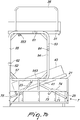
- the base 2 can comprise a supporting frame 600 that can rotate with respect to the base 2, in particular with respect to a longitudinal axis A thereof.
- Such supporting frame 600 can be pivoted to a front longitudinal member of the base 2 by means of two props 610 connected by a crossmember 620, which preferably has a longitudinal extension that is substantially equal to that of the longitudinal members 32 of the upper bed frame 3.
- the props 610 instead have an extension that is substantially equal to or greater than the difference in height, with respect to the plane of the base 2, between the pivoting axis A of the supporting frame 600 and the upper bed frame 3 when the latter is in the fully raised position.
- the corresponding crossmember 620 is at a height, with respect to the plane of the base 2, that is substantially equal to the height of the upper bed frame 3 and the props 610 consequently can be used to support frontally the weight that bears on the upper bed frame 3 and discharge it onto the base 2.
- the supporting frame 600 When instead the supporting frame 600 is in the lowered position, it lies above the lower bed frame 4, more precisely above the mattress 43 arranged on the lower bed frame 4, so as to be visible when the upper bed frame 3 is moved to the raised position.
- a ladder 670 is defined that moves rigidly together with the supporting frame 600.
- One of the stringers of the ladder 670 can be one of the props 610, while the other stringer of the ladder 670 is fixed to the crossmember 620 at one end and is pivoted at the other end along the same pivoting axis A as the supporting frame 600.
- the rungs of the ladder 670 are thus fixed to these two uprights, for example by welding.
- An assembly 640 for locking the movement of the upper bed frame 3 is provided on the crossmember 620 of the supporting frame 600 and is adapted to interact with the front longitudinal member 32 of the upper bed frame 3 when the supporting frame 600 is in the raised position, in order to maintain this position and allow the discharge of the weight onto the base 2.
- This locking assembly 640 can be obtained by means of at least one bolt coupled to the crossmember 620.
- the bolt interacts with suitable abutments 660 that are fixed rigidly to the upper bed frame 3, for example to the longitudinal member 32.
- a safety barrier 630 can be pivoted to the crossmember 620 of the supporting frame 600 and can rotate between an inactive position, in which the safety barrier can rotate freely with respect to the supporting frame 600, and a safety position, in which the barrier 630 is external to the perimeter of the supporting frame 600 and lies in a locked condition on a plane that is substantially perpendicular to the plane of the upper bed frame 3. In the safety position, the rotation of the safety barrier 630 is locked.
- the safety barrier 630 can integrate the locking assembly 640.
- bolts 650 are fixed rigidly to the safety barrier 630 substantially at the pivoting axis of the safety barrier on the cross-member 620 of the supporting frame 600.
- each bolt 650 is oriented substantially parallel to the cross-member 620 of the supporting frame 600.
- each bolt 650 can be fixed to one of the two arms of a fork that is fitted rotatably on the crossmember 620, the other arm of the fork being fixed to the safety barrier 630.
- the safety barrier 630 can further slide along the crossmember 620 so that when the safety barrier 630 slides the bolts 650 engage the corresponding abutments 660, for example tubular elements, that are fixed on the longitudinal member 32 of the upper bed frame 3.
- a safety lock 680 which can be operated by means of a removable key and prevents, once actuated, the sliding of the safety barrier 630 along the crossmember 620.
- the lock 680 for example, can interact with an abutment 690 that protrudes from the cross member 620 of the supporting frame 600.
- said abutment can be provided on the longitudinal member 32 of the upper bed frame 3.
- the spring latch 700 adapted to engage automatically the upper bed frame 3 by means of a spring that is loaded toward said upper bed frame, in order to prevent the supporting frame 600 from falling during the operations for moving the safety barrier 630.
- the spring latch 700 can be deactivated by pulling manually an eyelet that is integral with the spring latch. In order to maximize the safety of the structure, however, it is preferable to avoid the use of the spring latch 700.
- the safety barrier 630 is then made to rotate further so as to move it to the safety position. In this position, the bolts 650 are aligned with respect to the corresponding eyelets 660 of the upper bed frame 3. Finally, the user pushes the safety barrier 630 so as to make it slide with respect to the crossmember 620 of the supporting frame 600 and insert the bolts 650 in the eyelets 660.
- the frame 600 therefore, can support the weight of the upper bed while remaining locked in position. In this position, the user can use the ladder 670 that is integrated in the supporting frame 600.
- the safety barrier 630 is translated along the crossmember 620 so as to move the bolts 650 away from the eyelets 660 and the entire supporting frame 600 is finally accompanied by the user until it lies on the mattress 43 of the lower bed frame 4.
- closure of the bunk-bed is achieved with the upper bed frame which always remains substantially parallel to the floor and by using lever systems that can move exclusively on substantially vertical planes, interposed advantageously between the lateral sides of the base and the crossmembers of the upper and lower bed frames.
- the safety mechanism according to the invention which can be used with the described mechanism for collapsible bunk-beds but also with other mechanisms adapted to collapse bunk-beds, in fact must be considered by the user, since in addition to being clearly visible because it lies on the mattress of the lower bed it prevents the user from accessing the lower bed. Moreover, thanks to the integrated ladder, access to the upper bed is prevented if the safety mechanism is not activated.
- the safety mechanism according to the invention prevents the user from having to remember to assemble such barrier before lying on the upper bed.
- the materials used, as well as the dimensions may be any according to the requirements and to the state of the art.
Landscapes
- Special Chairs (AREA)
- Invalid Beds And Related Equipment (AREA)
Priority Applications (3)
| Application Number | Priority Date | Filing Date | Title |
|---|---|---|---|
| PL13707871T PL2844110T3 (pl) | 2012-03-06 | 2013-03-06 | Mechanizm do składanych łóżek piętrowych |
| RS20190417A RS58598B1 (sr) | 2012-03-06 | 2013-03-06 | Mehanizam za sklopive krevete na sprat |
| HRP20190552TT HRP20190552T1 (hr) | 2012-03-06 | 2013-03-06 | Mehanizam za sklopive krevete na kat |
Applications Claiming Priority (3)
| Application Number | Priority Date | Filing Date | Title |
|---|---|---|---|
| IT000341A ITMI20120341A1 (it) | 2012-03-06 | 2012-03-06 | Meccanismo per letti a castello richiudibili. |
| IT000632A ITMI20120632A1 (it) | 2012-04-17 | 2012-04-17 | Meccanismo di sicurezza per letti a castello richiudibili. |
| PCT/EP2013/054482 WO2013131946A1 (en) | 2012-03-06 | 2013-03-06 | Mechanism for collapsible bunk-beds |
Publications (2)
| Publication Number | Publication Date |
|---|---|
| EP2844110A1 EP2844110A1 (en) | 2015-03-11 |
| EP2844110B1 true EP2844110B1 (en) | 2019-01-02 |
Family
ID=47833074
Family Applications (1)
| Application Number | Title | Priority Date | Filing Date |
|---|---|---|---|
| EP13707871.3A Active EP2844110B1 (en) | 2012-03-06 | 2013-03-06 | Mechanism for collapsible bunk-beds |
Country Status (7)
| Country | Link |
|---|---|
| EP (1) | EP2844110B1 (pl) |
| ES (1) | ES2718176T3 (pl) |
| HR (1) | HRP20190552T1 (pl) |
| PL (1) | PL2844110T3 (pl) |
| PT (1) | PT2844110T (pl) |
| RS (1) | RS58598B1 (pl) |
| WO (1) | WO2013131946A1 (pl) |
Families Citing this family (7)
| Publication number | Priority date | Publication date | Assignee | Title |
|---|---|---|---|---|
| US10086915B2 (en) | 2015-10-30 | 2018-10-02 | Lippert Components, Inc. | Collapsible privacy enclosure |
| US20170143129A1 (en) * | 2015-11-25 | 2017-05-25 | Flexsteel Industries, Inc. | Sofa convertible into bunk bed |
| ITUB20160300A1 (it) * | 2016-01-15 | 2017-07-15 | Cannito Sas Di Cannito Michele | Meccanismo per letti a castello trasformabili |
| PL3403537T3 (pl) * | 2017-05-17 | 2019-09-30 | Daniel Gerhard | Łóżko oszczędzające przestrzeń |
| CN107280319A (zh) * | 2017-08-14 | 2017-10-24 | 安徽理工大学 | 一种自由升降双层床 |
| CN108338578A (zh) * | 2017-11-05 | 2018-07-31 | 无锡德林防务装备股份有限公司 | 沙发式隐藏双层床 |
| JP2022039840A (ja) * | 2020-08-28 | 2022-03-10 | オリジン株式会社 | ベッド |
Family Cites Families (7)
| Publication number | Priority date | Publication date | Assignee | Title |
|---|---|---|---|---|
| GB621095A (en) * | 1944-12-21 | 1949-04-04 | Birger Nordby | Improvements in double ottomans |
| FR981385A (fr) * | 1948-12-31 | 1951-05-25 | Boe Ry & Cie | Lits superposés repliables |
| DE2241842A1 (de) * | 1972-08-25 | 1974-03-07 | Meyer Heinz | Bett |
| US5263210A (en) * | 1993-02-24 | 1993-11-23 | Pollard Trevor S | Space saving bed |
| ITMI20080677A1 (it) * | 2008-04-15 | 2009-10-16 | Stema Srl | Meccanismo per letti a castello e divano letto comprendente questo meccanismo |
| ITMI20120341A1 (it) | 2012-03-06 | 2013-09-07 | Giulio Manzoni | Meccanismo per letti a castello richiudibili. |
| ITMI20120632A1 (it) | 2012-04-17 | 2013-10-18 | Giulio Manzoni | Meccanismo di sicurezza per letti a castello richiudibili. |
-
2013
- 2013-03-06 PL PL13707871T patent/PL2844110T3/pl unknown
- 2013-03-06 RS RS20190417A patent/RS58598B1/sr unknown
- 2013-03-06 EP EP13707871.3A patent/EP2844110B1/en active Active
- 2013-03-06 HR HRP20190552TT patent/HRP20190552T1/hr unknown
- 2013-03-06 PT PT13707871T patent/PT2844110T/pt unknown
- 2013-03-06 ES ES13707871T patent/ES2718176T3/es active Active
- 2013-03-06 WO PCT/EP2013/054482 patent/WO2013131946A1/en not_active Ceased
Non-Patent Citations (1)
| Title |
|---|
| None * |
Also Published As
| Publication number | Publication date |
|---|---|
| PL2844110T3 (pl) | 2019-06-28 |
| ES2718176T3 (es) | 2019-06-28 |
| RS58598B1 (sr) | 2019-05-31 |
| PT2844110T (pt) | 2019-04-29 |
| WO2013131946A1 (en) | 2013-09-12 |
| EP2844110A1 (en) | 2015-03-11 |
| HRP20190552T1 (hr) | 2019-05-03 |
Similar Documents
| Publication | Publication Date | Title |
|---|---|---|
| EP2844110B1 (en) | Mechanism for collapsible bunk-beds | |
| RU2536227C1 (ru) | Защелкивающаяся по углам игровая площадка | |
| EP2661990B1 (en) | Vertically-elevating sliding foldable frame | |
| EP1810650B1 (en) | Patient support apparatus having auto contour | |
| US3101064A (en) | Folding table construction | |
| EP1712151B1 (en) | Nesting and folding table | |
| US2230015A (en) | Knock-down load support | |
| JP3443577B2 (ja) | 折畳み式卓球台 | |
| DK3192942T3 (en) | SCALE COVER comprising two ladder units kept at a distance from a pre-assembled collapsible base | |
| US3112954A (en) | Table and bench assembly | |
| US12043475B2 (en) | Collapsible shipping container | |
| US9738116B1 (en) | Mobile folding restaurant booth style bench | |
| WO2014132281A1 (en) | Folding scaffold with built in ladder | |
| US20080016617A1 (en) | Furniture element forming convertible desk and bed | |
| EP2378052A2 (en) | Folding stepladder | |
| EP3192940B1 (fr) | Echafaudage comportant deux echelles deployables et supportant un garde-corps | |
| CN111619630B (zh) | 拖车 | |
| EP2151223B1 (en) | Bed with interconnectable barrier elements | |
| CN116268872B (zh) | 一种折叠游戏床及操作方法 | |
| EP3981293B1 (en) | Compact folding frame for a folding furniture such as a sofa bed | |
| EP4328150A1 (en) | Folding transport container | |
| WO2007110888A1 (en) | Foldable stepladder with foldable handrail | |
| US795174A (en) | Knockdown chair. | |
| ITMI20120341A1 (it) | Meccanismo per letti a castello richiudibili. | |
| ITMI20120632A1 (it) | Meccanismo di sicurezza per letti a castello richiudibili. |
Legal Events
| Date | Code | Title | Description |
|---|---|---|---|
| PUAI | Public reference made under article 153(3) epc to a published international application that has entered the european phase |
Free format text: ORIGINAL CODE: 0009012 |
|
| 17P | Request for examination filed |
Effective date: 20141125 |
|
| AK | Designated contracting states |
Kind code of ref document: A1 Designated state(s): AL AT BE BG CH CY CZ DE DK EE ES FI FR GB GR HR HU IE IS IT LI LT LU LV MC MK MT NL NO PL PT RO RS SE SI SK SM TR |
|
| AX | Request for extension of the european patent |
Extension state: BA ME |
|
| GRAP | Despatch of communication of intention to grant a patent |
Free format text: ORIGINAL CODE: EPIDOSNIGR1 |
|
| STAA | Information on the status of an ep patent application or granted ep patent |
Free format text: STATUS: GRANT OF PATENT IS INTENDED |
|
| INTG | Intention to grant announced |
Effective date: 20180717 |
|
| GRAS | Grant fee paid |
Free format text: ORIGINAL CODE: EPIDOSNIGR3 |
|
| GRAA | (expected) grant |
Free format text: ORIGINAL CODE: 0009210 |
|
| STAA | Information on the status of an ep patent application or granted ep patent |
Free format text: STATUS: THE PATENT HAS BEEN GRANTED |
|
| AK | Designated contracting states |
Kind code of ref document: B1 Designated state(s): AL AT BE BG CH CY CZ DE DK EE ES FI FR GB GR HR HU IE IS IT LI LT LU LV MC MK MT NL NO PL PT RO RS SE SI SK SM TR |
|
| AX | Request for extension of the european patent |
Extension state: BA ME |
|
| REG | Reference to a national code |
Ref country code: GB Ref legal event code: FG4D |
|
| REG | Reference to a national code |
Ref country code: CH Ref legal event code: EP Ref country code: AT Ref legal event code: REF Ref document number: 1083328 Country of ref document: AT Kind code of ref document: T Effective date: 20190115 |
|
| REG | Reference to a national code |
Ref country code: IE Ref legal event code: FG4D |
|
| REG | Reference to a national code |
Ref country code: DE Ref legal event code: R096 Ref document number: 602013049136 Country of ref document: DE |
|
| REG | Reference to a national code |
Ref country code: HR Ref legal event code: TUEP Ref document number: P20190552 Country of ref document: HR |
|
| REG | Reference to a national code |
Ref country code: RO Ref legal event code: EPE |
|
| REG | Reference to a national code |
Ref country code: NL Ref legal event code: FP |
|
| REG | Reference to a national code |
Ref country code: HR Ref legal event code: ODRP Ref document number: P20190552 Country of ref document: HR Payment date: 20190321 Year of fee payment: 7 |
|
| REG | Reference to a national code |
Ref country code: PT Ref legal event code: SC4A Ref document number: 2844110 Country of ref document: PT Date of ref document: 20190429 Kind code of ref document: T Free format text: AVAILABILITY OF NATIONAL TRANSLATION Effective date: 20190402 |
|
| REG | Reference to a national code |
Ref country code: HR Ref legal event code: T1PR Ref document number: P20190552 Country of ref document: HR |
|
| REG | Reference to a national code |
Ref country code: LT Ref legal event code: MG4D |
|
| REG | Reference to a national code |
Ref country code: NO Ref legal event code: T2 Effective date: 20190102 |
|
| REG | Reference to a national code |
Ref country code: AT Ref legal event code: MK05 Ref document number: 1083328 Country of ref document: AT Kind code of ref document: T Effective date: 20190102 |
|
| REG | Reference to a national code |
Ref country code: ES Ref legal event code: FG2A Ref document number: 2718176 Country of ref document: ES Kind code of ref document: T3 Effective date: 20190628 |
|
| PG25 | Lapsed in a contracting state [announced via postgrant information from national office to epo] |
Ref country code: SE Free format text: LAPSE BECAUSE OF FAILURE TO SUBMIT A TRANSLATION OF THE DESCRIPTION OR TO PAY THE FEE WITHIN THE PRESCRIBED TIME-LIMIT Effective date: 20190102 Ref country code: LT Free format text: LAPSE BECAUSE OF FAILURE TO SUBMIT A TRANSLATION OF THE DESCRIPTION OR TO PAY THE FEE WITHIN THE PRESCRIBED TIME-LIMIT Effective date: 20190102 |
|
| PG25 | Lapsed in a contracting state [announced via postgrant information from national office to epo] |
Ref country code: BG Free format text: LAPSE BECAUSE OF FAILURE TO SUBMIT A TRANSLATION OF THE DESCRIPTION OR TO PAY THE FEE WITHIN THE PRESCRIBED TIME-LIMIT Effective date: 20190402 Ref country code: GR Free format text: LAPSE BECAUSE OF FAILURE TO SUBMIT A TRANSLATION OF THE DESCRIPTION OR TO PAY THE FEE WITHIN THE PRESCRIBED TIME-LIMIT Effective date: 20190403 Ref country code: LV Free format text: LAPSE BECAUSE OF FAILURE TO SUBMIT A TRANSLATION OF THE DESCRIPTION OR TO PAY THE FEE WITHIN THE PRESCRIBED TIME-LIMIT Effective date: 20190102 Ref country code: IS Free format text: LAPSE BECAUSE OF FAILURE TO SUBMIT A TRANSLATION OF THE DESCRIPTION OR TO PAY THE FEE WITHIN THE PRESCRIBED TIME-LIMIT Effective date: 20190502 |
|
| REG | Reference to a national code |
Ref country code: DE Ref legal event code: R097 Ref document number: 602013049136 Country of ref document: DE |
|
| PG25 | Lapsed in a contracting state [announced via postgrant information from national office to epo] |
Ref country code: CZ Free format text: LAPSE BECAUSE OF FAILURE TO SUBMIT A TRANSLATION OF THE DESCRIPTION OR TO PAY THE FEE WITHIN THE PRESCRIBED TIME-LIMIT Effective date: 20190102 Ref country code: AL Free format text: LAPSE BECAUSE OF FAILURE TO SUBMIT A TRANSLATION OF THE DESCRIPTION OR TO PAY THE FEE WITHIN THE PRESCRIBED TIME-LIMIT Effective date: 20190102 Ref country code: SK Free format text: LAPSE BECAUSE OF FAILURE TO SUBMIT A TRANSLATION OF THE DESCRIPTION OR TO PAY THE FEE WITHIN THE PRESCRIBED TIME-LIMIT Effective date: 20190102 Ref country code: MC Free format text: LAPSE BECAUSE OF FAILURE TO SUBMIT A TRANSLATION OF THE DESCRIPTION OR TO PAY THE FEE WITHIN THE PRESCRIBED TIME-LIMIT Effective date: 20190102 Ref country code: AT Free format text: LAPSE BECAUSE OF FAILURE TO SUBMIT A TRANSLATION OF THE DESCRIPTION OR TO PAY THE FEE WITHIN THE PRESCRIBED TIME-LIMIT Effective date: 20190102 Ref country code: EE Free format text: LAPSE BECAUSE OF FAILURE TO SUBMIT A TRANSLATION OF THE DESCRIPTION OR TO PAY THE FEE WITHIN THE PRESCRIBED TIME-LIMIT Effective date: 20190102 Ref country code: DK Free format text: LAPSE BECAUSE OF FAILURE TO SUBMIT A TRANSLATION OF THE DESCRIPTION OR TO PAY THE FEE WITHIN THE PRESCRIBED TIME-LIMIT Effective date: 20190102 |
|
| REG | Reference to a national code |
Ref country code: CH Ref legal event code: PL |
|
| PLBE | No opposition filed within time limit |
Free format text: ORIGINAL CODE: 0009261 |
|
| STAA | Information on the status of an ep patent application or granted ep patent |
Free format text: STATUS: NO OPPOSITION FILED WITHIN TIME LIMIT |
|
| PG25 | Lapsed in a contracting state [announced via postgrant information from national office to epo] |
Ref country code: LU Free format text: LAPSE BECAUSE OF NON-PAYMENT OF DUE FEES Effective date: 20190306 Ref country code: SM Free format text: LAPSE BECAUSE OF FAILURE TO SUBMIT A TRANSLATION OF THE DESCRIPTION OR TO PAY THE FEE WITHIN THE PRESCRIBED TIME-LIMIT Effective date: 20190102 |
|
| REG | Reference to a national code |
Ref country code: BE Ref legal event code: MM Effective date: 20190331 |
|
| 26N | No opposition filed |
Effective date: 20191003 |
|
| PG25 | Lapsed in a contracting state [announced via postgrant information from national office to epo] |
Ref country code: IE Free format text: LAPSE BECAUSE OF NON-PAYMENT OF DUE FEES Effective date: 20190306 Ref country code: LI Free format text: LAPSE BECAUSE OF NON-PAYMENT OF DUE FEES Effective date: 20190331 Ref country code: CH Free format text: LAPSE BECAUSE OF NON-PAYMENT OF DUE FEES Effective date: 20190331 |
|
| PG25 | Lapsed in a contracting state [announced via postgrant information from national office to epo] |
Ref country code: SI Free format text: LAPSE BECAUSE OF FAILURE TO SUBMIT A TRANSLATION OF THE DESCRIPTION OR TO PAY THE FEE WITHIN THE PRESCRIBED TIME-LIMIT Effective date: 20190102 Ref country code: BE Free format text: LAPSE BECAUSE OF NON-PAYMENT OF DUE FEES Effective date: 20190331 |
|
| REG | Reference to a national code |
Ref country code: HR Ref legal event code: ODRP Ref document number: P20190552 Country of ref document: HR Payment date: 20200224 Year of fee payment: 8 |
|
| PG25 | Lapsed in a contracting state [announced via postgrant information from national office to epo] |
Ref country code: MT Free format text: LAPSE BECAUSE OF NON-PAYMENT OF DUE FEES Effective date: 20190306 |
|
| REG | Reference to a national code |
Ref country code: HR Ref legal event code: ODRP Ref document number: P20190552 Country of ref document: HR Payment date: 20210225 Year of fee payment: 9 |
|
| PG25 | Lapsed in a contracting state [announced via postgrant information from national office to epo] |
Ref country code: CY Free format text: LAPSE BECAUSE OF FAILURE TO SUBMIT A TRANSLATION OF THE DESCRIPTION OR TO PAY THE FEE WITHIN THE PRESCRIBED TIME-LIMIT Effective date: 20190102 |
|
| PG25 | Lapsed in a contracting state [announced via postgrant information from national office to epo] |
Ref country code: HU Free format text: LAPSE BECAUSE OF FAILURE TO SUBMIT A TRANSLATION OF THE DESCRIPTION OR TO PAY THE FEE WITHIN THE PRESCRIBED TIME-LIMIT; INVALID AB INITIO Effective date: 20130306 |
|
| REG | Reference to a national code |
Ref country code: HR Ref legal event code: ODRP Ref document number: P20190552 Country of ref document: HR Payment date: 20220225 Year of fee payment: 10 |
|
| PG25 | Lapsed in a contracting state [announced via postgrant information from national office to epo] |
Ref country code: MK Free format text: LAPSE BECAUSE OF FAILURE TO SUBMIT A TRANSLATION OF THE DESCRIPTION OR TO PAY THE FEE WITHIN THE PRESCRIBED TIME-LIMIT Effective date: 20190102 |
|
| REG | Reference to a national code |
Ref country code: HR Ref legal event code: ODRP Ref document number: P20190552 Country of ref document: HR Payment date: 20230228 Year of fee payment: 11 |
|
| PGFP | Annual fee paid to national office [announced via postgrant information from national office to epo] |
Ref country code: RS Payment date: 20230131 Year of fee payment: 11 Ref country code: HR Payment date: 20230228 Year of fee payment: 11 |
|
| P01 | Opt-out of the competence of the unified patent court (upc) registered |
Effective date: 20230528 |
|
| REG | Reference to a national code |
Ref country code: HR Ref legal event code: PBON Ref document number: P20190552 Country of ref document: HR Effective date: 20240306 |
|
| PG25 | Lapsed in a contracting state [announced via postgrant information from national office to epo] |
Ref country code: HR Free format text: LAPSE BECAUSE OF NON-PAYMENT OF DUE FEES Effective date: 20240306 |
|
| PG25 | Lapsed in a contracting state [announced via postgrant information from national office to epo] |
Ref country code: HR Free format text: LAPSE BECAUSE OF NON-PAYMENT OF DUE FEES Effective date: 20240306 Ref country code: RS Free format text: LAPSE BECAUSE OF NON-PAYMENT OF DUE FEES Effective date: 20240306 |
|
| PGFP | Annual fee paid to national office [announced via postgrant information from national office to epo] |
Ref country code: DE Payment date: 20250313 Year of fee payment: 13 Ref country code: PT Payment date: 20250221 Year of fee payment: 13 |
|
| PGFP | Annual fee paid to national office [announced via postgrant information from national office to epo] |
Ref country code: RO Payment date: 20250303 Year of fee payment: 13 Ref country code: FI Payment date: 20250313 Year of fee payment: 13 Ref country code: NL Payment date: 20250313 Year of fee payment: 13 |
|
| PGFP | Annual fee paid to national office [announced via postgrant information from national office to epo] |
Ref country code: NO Payment date: 20250314 Year of fee payment: 13 |
|
| PGFP | Annual fee paid to national office [announced via postgrant information from national office to epo] |
Ref country code: FR Payment date: 20250227 Year of fee payment: 13 Ref country code: PL Payment date: 20250228 Year of fee payment: 13 |
|
| PGFP | Annual fee paid to national office [announced via postgrant information from national office to epo] |
Ref country code: IT Payment date: 20250220 Year of fee payment: 13 Ref country code: GB Payment date: 20250219 Year of fee payment: 13 |
|
| PGFP | Annual fee paid to national office [announced via postgrant information from national office to epo] |
Ref country code: TR Payment date: 20250225 Year of fee payment: 13 |
|
| PGFP | Annual fee paid to national office [announced via postgrant information from national office to epo] |
Ref country code: ES Payment date: 20250401 Year of fee payment: 13 |