EP2843809A2 - Housing for an electric motor having low vibration - Google Patents
Housing for an electric motor having low vibration Download PDFInfo
- Publication number
- EP2843809A2 EP2843809A2 EP14182360.9A EP14182360A EP2843809A2 EP 2843809 A2 EP2843809 A2 EP 2843809A2 EP 14182360 A EP14182360 A EP 14182360A EP 2843809 A2 EP2843809 A2 EP 2843809A2
- Authority
- EP
- European Patent Office
- Prior art keywords
- housing
- inclined surface
- motor
- insulator
- protruding portion
- Prior art date
- Legal status (The legal status is an assumption and is not a legal conclusion. Google has not performed a legal analysis and makes no representation as to the accuracy of the status listed.)
- Granted
Links
Images

Classifications
-
- H—ELECTRICITY
- H02—GENERATION; CONVERSION OR DISTRIBUTION OF ELECTRIC POWER
- H02K—DYNAMO-ELECTRIC MACHINES
- H02K3/00—Details of windings
- H02K3/32—Windings characterised by the shape, form or construction of the insulation
-
- H—ELECTRICITY
- H02—GENERATION; CONVERSION OR DISTRIBUTION OF ELECTRIC POWER
- H02K—DYNAMO-ELECTRIC MACHINES
- H02K5/00—Casings; Enclosures; Supports
- H02K5/24—Casings; Enclosures; Supports specially adapted for suppression or reduction of noise or vibrations
-
- H—ELECTRICITY
- H02—GENERATION; CONVERSION OR DISTRIBUTION OF ELECTRIC POWER
- H02K—DYNAMO-ELECTRIC MACHINES
- H02K3/00—Details of windings
- H02K3/32—Windings characterised by the shape, form or construction of the insulation
- H02K3/38—Windings characterised by the shape, form or construction of the insulation around winding heads, equalising connectors, or connections thereto
-
- H—ELECTRICITY
- H02—GENERATION; CONVERSION OR DISTRIBUTION OF ELECTRIC POWER
- H02K—DYNAMO-ELECTRIC MACHINES
- H02K3/00—Details of windings
- H02K3/32—Windings characterised by the shape, form or construction of the insulation
- H02K3/34—Windings characterised by the shape, form or construction of the insulation between conductors or between conductor and core, e.g. slot insulation
- H02K3/345—Windings characterised by the shape, form or construction of the insulation between conductors or between conductor and core, e.g. slot insulation between conductor and core, e.g. slot insulation
-
- H—ELECTRICITY
- H02—GENERATION; CONVERSION OR DISTRIBUTION OF ELECTRIC POWER
- H02K—DYNAMO-ELECTRIC MACHINES
- H02K3/00—Details of windings
- H02K3/46—Fastening of windings on the stator or rotor structure
-
- H—ELECTRICITY
- H02—GENERATION; CONVERSION OR DISTRIBUTION OF ELECTRIC POWER
- H02K—DYNAMO-ELECTRIC MACHINES
- H02K2203/00—Specific aspects not provided for in the other groups of this subclass relating to the windings
- H02K2203/12—Machines characterised by the bobbins for supporting the windings
-
- H—ELECTRICITY
- H02—GENERATION; CONVERSION OR DISTRIBUTION OF ELECTRIC POWER
- H02K—DYNAMO-ELECTRIC MACHINES
- H02K3/00—Details of windings
- H02K3/32—Windings characterised by the shape, form or construction of the insulation
- H02K3/325—Windings characterised by the shape, form or construction of the insulation for windings on salient poles, such as claw-shaped poles
-
- H—ELECTRICITY
- H02—GENERATION; CONVERSION OR DISTRIBUTION OF ELECTRIC POWER
- H02K—DYNAMO-ELECTRIC MACHINES
- H02K5/00—Casings; Enclosures; Supports
- H02K5/04—Casings or enclosures characterised by the shape, form or construction thereof
- H02K5/16—Means for supporting bearings, e.g. insulating supports or means for fitting bearings in the bearing-shields
- H02K5/173—Means for supporting bearings, e.g. insulating supports or means for fitting bearings in the bearing-shields using bearings with rolling contact, e.g. ball bearings
- H02K5/1732—Means for supporting bearings, e.g. insulating supports or means for fitting bearings in the bearing-shields using bearings with rolling contact, e.g. ball bearings radially supporting the rotary shaft at both ends of the rotor
Definitions
- the present invention relates to a motor.
- an Electronic Power Steering (EPS) System is a device for securing steering stability of a vehicle, and functions to provide a torque in a steering direction of a driver using a motor and thus to allow easy handling.
- EPS Electronic Power Steering
- the EPS system can control an operation of the motor according to driving conditions, and thus can enhance steering performance and steering feeling.
- an electronic control unit drives the motor according to the driving conditions detected by a vehicle speed sensor, a torque angle sensor, a torque sensor, and the like, secures turning stability, provides rapid resilience, and thus enables a driver to safely drive a vehicle.
- the motor used in the EPS system has a cylindrical shape, and an exterior thereof is formed by a housing of which an upper portion is opened and a bracket coupled to the upper portion of the housing, and a stator is disposed in the housing.
- a rotator rotated according to an electromagnetic interaction with the stator is disposed at a center of the stator.
- the rotor is rotatably supported by a rotational shaft.
- a vehicle steering shaft is connected to an upper portion of the rotational shaft to provide power to assist a steering operation.
- the motor generates vibration and noise at a high frequency area, and this phenomenon is associated with a resonant frequency. Therefore, it is necessary to shift or improve the resonant frequency, thereby reducing the vibration and the noise.
- a material of the housing may be changed from iron to aluminum, or a thickness of the housing may be adjusted.
- material costs and manufacturing costs are increased.
- the present invention is directed to a motor capable of reducing vibration and noise generated from a housing without changing a material or a thickness of the housing.
- a motor including: a housing having a protruding portion; a stator including a stator core disposed at an inner circumferential surface of the housing, a coil wound on the stator core, and an insulator disposed between the stator core and the coil; a rotor disposed to be rotatable together with the stator; and a rotational shaft interlocked and rotated with the rotor, wherein the protruding portion includes an inclined surface in contact with the insulator.
- the protruding portion may include a first inclined surface configured to protrude inside the housing to be in contact with the insulator, and a second inclined surface connected with the first inclined surface.
- the second inclined surface may support a bearing configured to support the rotational shaft.
- the motor may further include a bottom surface configured to connect the first inclined surface with the second inclined surface.
- the motor may further include a reinforcing member arranged in a space defined by the first inclined surface, the second inclined surface, and the bottom surface.
- the insulator may include an end bent to be in contact with the inclined surface of the protruding portion.
- the insulator may include an inclined contacting surface configured to be in contact with the inclined surface of the protruding portion.
- a ratio of a height of the end of the insulator and a thickness of the housing may be 1:8 to 1:20.
- a motor including: a housing; a stator including a stator core disposed at an inner circumferential surface of the housing, a coil wound on the stator core, and an insulator disposed between the stator core and the coil; a rotor disposed to be rotatable together with the stator; and a rotational shaft interlocked and rotated with the rotor, wherein an operating noise is 30 dB or less at a frequency band of 2.5 to 3.5 kHz.
- a motor including: a housing having a protruding portion; a stator including a stator core disposed at an inner circumferential surface of the housing, a coil wound on the stator core, and an insulator disposed between the stator core and the coil; a rotor disposed to be rotatable together with the stator; and a rotational shaft interlocked and rotated with the rotor, wherein the protruding portion includes a first inclined surface configured to protrude inside the housing to be in contact with the insulator, and a second inclined surface configured to support a bearing configured to support the rotational shaft.
- first, second, etc. can be used to describe various construction elements, but the construction elements should not be limited by those terms. The terms are used merely for the purpose to distinguish an element from another element. For example, a first element may be named to a second element, and similarly, a second element may be named to a first element without departing from the scope of right of the invention.
- a certain construction element is connected to another construction element
- the expression that "a certain construction element is connected to another construction element” means that the certain construction element is directly connected to another construction element, and also means that a third construction element may be interposed therebetween.
- the expression that "the certain construction element is directly connected to another construction element” means that the third construction element is not interposed therebetween.
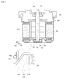
- FIG. 1 is a cross-sectional view illustrating a motor according to one embodiment of the present invention
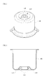
- FIG. 2 is a bottom perspective view illustrating a housing of the motor according to one embodiment of the present invention
- FIG. 3 is a side cross-sectional view illustrating the housing of the motor according to one embodiment of the present invention.
- the motor includes a housing 100, a bracket 200 coupled to an upper portion of the housing 100, a rotational shaft 320 supported by the housing 100 and the bracket 200, a stator 400 coupled to an inner circumferential surface of the housing 100, a rotor 310 coupled to an outer circumferential surface of the rotational shaft 320, and an upper bearing 131 and a lower bearing 132 which support the rotational shaft 320.
- the motor may be used for an Electronic Power Steering (EPS) System.
- EPS Electronic Power Steering
- the housing 100 has a cylindrical shape of which an upper portion is opened.
- a ring-shaped protruding portion 110 is formed at a lower surface 120 of the housing 100, and a lower bearing pocket portion 102 in which the lower bearing 132 is installed is formed by the protruding portion 110.
- the annular protruding portion 110 may be formed by pressing the lower surface of the housing 100 using a pressing member.
- the bracket 200 is coupled to an upper portion of the housing 100, and has an upper bearing pocket portion 201 in which the upper bearing 131 is installed.
- the upper and lower bearings 131 and 132 are installed in the upper and lower bearing pocket portions 201 and 102 in a fitting manner so as to respectively support the rotational shaft 320 at upper and lower sides of the rotational shaft 320.
- the stator 400 includes a stator core 410, a coil 420, and an insulator 430.
- the stator core 410 has a plurality of teeth which protrude toward a center, and the coil 420 is wound on each tooth.
- the insulator 430 is disposed between the stator core 410 and the coil 420 to insulate the coil 420 from the stator core 410.
- the rotor 310 is disposed to be rotatable together with the stator 400, and a plurality of magnets are installed at an outer circumferential surface of the rotor 310.
- the rotational shaft 320 is disposed at a center of the housing 100 and the bracket 200 to be interlocked and rotated with the rotor 310.
- the rotational shaft 320 is rotatably supported by the upper bearing 131 installed at the bracket 200 and the lower bearing 132 installed at the lower surface of the housing 100.
- the insulator 430 is in contact with the protruding portion 110 formed to protrude inside the housing 100.
- the protruding portion 110 includes a first inclined surface 112 which protrudes inside the housing 100 to be in contact with the insulator 430, a second inclined surface 113 which supports the lower bearing 132, and a bottom surface 111 which connects the first inclined surface 112 with the second inclined surface 113.
- the second inclined surface 113 of the protruding portion 110 may be disposed vertically to the lower surface 120 of the housing 100 in order to form the lower bearing pocket portion 102 in which the lower bearing 132 is installed.
- An inclination angle of the first inclined surface 112 may be adjusted to be directly in contact with the second inclined surface 113.
- the bottom surface 111 may be omitted.
- a reinforcing member 500 may be disposed in a space defined at a lower side of the housing 100 by the protruding portion 110.
- the reinforcing member 500 may be formed by filling the space with a rubber material or a resin.
- a kind and a material of the reinforcing member 500 are not specially limited.
- the first inclined surface 112 of the protruding portion 110 may be formed to have a predetermined slope ⁇ with respect to the lower surface 120 of the housing 100.
- a stress applied to the insulator 430 may be dispersed, and thus the insulator 430 may be prevented from being damaged.
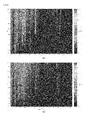
- FIG. 4 is a view illustrating noise measurement results of the motor according to one embodiment of the present invention.
- Table 1 Frequency band Operating noise (dB) Before improvement After improvement High frequency band (2.5 ⁇ 3.5 kHz) 38.3 25.7 Entire band 41.7 40.7
- the noise due to the resonant frequency is generated at a frequency area of 2.5 kHz.
- the resonant frequency is improved, and thus the noise is reduced.
- the noise generated from the housing 100 is reduced at a high frequency band of 2.5 to 3.5 kHz by 10 dB or more.
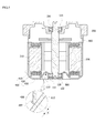
- FIG. 5 is a cross-sectional view illustrating a motor according to another embodiment of the present invention.
- the insulator 430 includes an end 432 which is bent and in contact with the first inclined surface 112 of the protruding portion 110.
- the end 432 may be formed to be bent by pressing a distal end of the insulator 430 to the protruding portion 110.
- a ratio of a height (a contacting length: h) of the bent end 432 and a thickness of the housing 100 may be 1:8 to 1:20.
- the thickness t of the housing 100 is 1.6 mm
- the height h of the bent portion may be 0.08 to 0.2 mm.
- the insulator 430 may support the housing 100 with a more potent force, and thus the vibration and the noise generated from the housing 100 may be further reduced.
- FIG. 6 is a cross-sectional view illustrating a motor according to still another embodiment of the present invention.
- the insulator 430 includes an inclined contacting surface 433 which is in contact with the first inclined surface 112 of the protruding portion 110.
- the inclined contacting surface 433 may have a slope corresponding to the slope ⁇ of the first inclined surface 112.
- a contact area between a lower end of the insulator 430 and an outer circumferential surface of the protruding portion 110 may be increased, and thus the housing 100 may be more stably supported.
- the vibration and the noise generated from the housing can be reduced without changing the material and the thickness of the housing.
- the insulator since the predetermined slope is provided at the lower surface of the housing, which is in contact with the insulator, to disperse the stress applied to the insulator, the insulator can be prevent from being damaged.
Landscapes
- Engineering & Computer Science (AREA)
- Power Engineering (AREA)
- Motor Or Generator Frames (AREA)
Abstract
Description
- This application claims priority to and the benefit of Korean Patent Application No.
2013-0105476, filed on September 3, 2013 - The present invention relates to a motor.
- Generally, an Electronic Power Steering (EPS) System is a device for securing steering stability of a vehicle, and functions to provide a torque in a steering direction of a driver using a motor and thus to allow easy handling.
- Unlike an existing hydraulic power steering (HPS) system, the EPS system can control an operation of the motor according to driving conditions, and thus can enhance steering performance and steering feeling.
- Specifically, in the EPS system, an electronic control unit (ECU) drives the motor according to the driving conditions detected by a vehicle speed sensor, a torque angle sensor, a torque sensor, and the like, secures turning stability, provides rapid resilience, and thus enables a driver to safely drive a vehicle.
- In general, the motor used in the EPS system has a cylindrical shape, and an exterior thereof is formed by a housing of which an upper portion is opened and a bracket coupled to the upper portion of the housing, and a stator is disposed in the housing.
- A rotator rotated according to an electromagnetic interaction with the stator is disposed at a center of the stator. The rotor is rotatably supported by a rotational shaft. A vehicle steering shaft is connected to an upper portion of the rotational shaft to provide power to assist a steering operation.
- Meanwhile, the motor generates vibration and noise at a high frequency area, and this phenomenon is associated with a resonant frequency. Therefore, it is necessary to shift or improve the resonant frequency, thereby reducing the vibration and the noise.
- To this end, a material of the housing may be changed from iron to aluminum, or a thickness of the housing may be adjusted. However, there is a problem in that material costs and manufacturing costs are increased.
- The present invention is directed to a motor capable of reducing vibration and noise generated from a housing without changing a material or a thickness of the housing.
- According to an aspect of the present invention, there is provided a motor including: a housing having a protruding portion; a stator including a stator core disposed at an inner circumferential surface of the housing, a coil wound on the stator core, and an insulator disposed between the stator core and the coil; a rotor disposed to be rotatable together with the stator; and a rotational shaft interlocked and rotated with the rotor, wherein the protruding portion includes an inclined surface in contact with the insulator.
- The protruding portion may include a first inclined surface configured to protrude inside the housing to be in contact with the insulator, and a second inclined surface connected with the first inclined surface.
- The second inclined surface may support a bearing configured to support the rotational shaft.
- The motor may further include a bottom surface configured to connect the first inclined surface with the second inclined surface.
- The motor may further include a reinforcing member arranged in a space defined by the first inclined surface, the second inclined surface, and the bottom surface.
- The insulator may include an end bent to be in contact with the inclined surface of the protruding portion.
- The insulator may include an inclined contacting surface configured to be in contact with the inclined surface of the protruding portion.
- A ratio of a height of the end of the insulator and a thickness of the housing may be 1:8 to 1:20.
- According to another aspect of the present invention, there is provided a motor including: a housing; a stator including a stator core disposed at an inner circumferential surface of the housing, a coil wound on the stator core, and an insulator disposed between the stator core and the coil; a rotor disposed to be rotatable together with the stator; and a rotational shaft interlocked and rotated with the rotor, wherein an operating noise is 30 dB or less at a frequency band of 2.5 to 3.5 kHz.
- According to still another aspect of the present invention, there is provided a motor including: a housing having a protruding portion; a stator including a stator core disposed at an inner circumferential surface of the housing, a coil wound on the stator core, and an insulator disposed between the stator core and the coil; a rotor disposed to be rotatable together with the stator; and a rotational shaft interlocked and rotated with the rotor, wherein the protruding portion includes a first inclined surface configured to protrude inside the housing to be in contact with the insulator, and a second inclined surface configured to support a bearing configured to support the rotational shaft.
- The above and other objects, features, and advantages of the present invention will become more apparent to those of ordinary skill in the art by describing in detail exemplary embodiments thereof with reference to the accompanying drawings, in which:
-
FIG. 1 is a cross-sectional view illustrating a motor according to one embodiment of the present invention; -
FIG. 2 is a bottom perspective view illustrating a housing of the motor according to one embodiment of the present invention; -
FIG. 3 is a side cross-sectional view illustrating the housing of the motor according to one embodiment of the present invention; -
FIG. 4 is a view illustrating noise measurement results of the motor according to one embodiment of the present invention; -
FIG. 5 is a cross-sectional view illustrating a motor according to another embodiment of the present invention; and -
FIG. 6 is a cross-sectional view illustrating a motor according to still another embodiment of the present invention. - Although the present invention can be modified variously and have several embodiments, specific exemplary embodiments are illustrated in the accompanying drawings and will be described in detail in the detailed description. However, the present invention is not limited to the embodiments, and it should be understood that the present invention encompasses all of equivalents and substitutes included in the technical scope and spirit of the invention.
- The terms including an ordinal number such as first, second, etc. can be used to describe various construction elements, but the construction elements should not be limited by those terms. The terms are used merely for the purpose to distinguish an element from another element. For example, a first element may be named to a second element, and similarly, a second element may be named to a first element without departing from the scope of right of the invention. The term of and/or encompasses a combination of plural items or any one of the plural items.
- It is to be noted that, in this specification, the expression that "a certain construction element is connected to another construction element" means that the certain construction element is directly connected to another construction element, and also means that a third construction element may be interposed therebetween. On the other hand, the expression that "the certain construction element is directly connected to another construction element" means that the third construction element is not interposed therebetween.
- The terms used herein are merely to describe a specific embodiment, and thus the present invention is not limited to them. Further, unless singular expression clearly denotes a different meaning in context, it includes plural expression. It is understood that terms "comprises," "comprising," "includes," or "has" intend to indicate the existence of features, numerals, steps, operations, elements, and components described in the specification or the existence of the combination of these, and do not exclude the existence of one or more other features, numerals, steps, operations, elements, and components or the existence of the combination of these or additional possibility beforehand.
- Unless otherwise defined, all terms including technical and scientific terms used herein have the same meaning as commonly understood by one of ordinary skill in the art to which this invention belongs. It will be further understood that terms, such as those defined in commonly used dictionaries, should be interpreted as having a meaning that is consistent with their meaning in the context of the relevant art and will not be interpreted in an idealized or overly formal sense unless expressly so defined here.
- Hereinafter, the exemplary embodiments of the present invention will be described in detail with reference to the accompanying drawings, however, like reference numerals refer to like or corresponding elements regardless of reference numerals and a detailed description thereof will be omitted.
-
FIG. 1 is a cross-sectional view illustrating a motor according to one embodiment of the present invention,FIG. 2 is a bottom perspective view illustrating a housing of the motor according to one embodiment of the present invention, andFIG. 3 is a side cross-sectional view illustrating the housing of the motor according to one embodiment of the present invention. - Referring to
FIGS. 1 to 3 , the motor according to one embodiment of the present invention includes ahousing 100, abracket 200 coupled to an upper portion of thehousing 100, arotational shaft 320 supported by thehousing 100 and thebracket 200, astator 400 coupled to an inner circumferential surface of thehousing 100, arotor 310 coupled to an outer circumferential surface of therotational shaft 320, and anupper bearing 131 and alower bearing 132 which support therotational shaft 320. The motor may be used for an Electronic Power Steering (EPS) System. - The
housing 100 has a cylindrical shape of which an upper portion is opened. A ring-shaped protruding portion 110 is formed at alower surface 120 of thehousing 100, and a lowerbearing pocket portion 102 in which thelower bearing 132 is installed is formed by theprotruding portion 110. Theannular protruding portion 110 may be formed by pressing the lower surface of thehousing 100 using a pressing member. - The
bracket 200 is coupled to an upper portion of thehousing 100, and has an upper bearingpocket portion 201 in which theupper bearing 131 is installed. - The upper and
lower bearings pocket portions rotational shaft 320 at upper and lower sides of therotational shaft 320. - The
stator 400 includes astator core 410, acoil 420, and aninsulator 430. Thestator core 410 has a plurality of teeth which protrude toward a center, and thecoil 420 is wound on each tooth. Theinsulator 430 is disposed between thestator core 410 and thecoil 420 to insulate thecoil 420 from thestator core 410. - The
rotor 310 is disposed to be rotatable together with thestator 400, and a plurality of magnets are installed at an outer circumferential surface of therotor 310. - The
rotational shaft 320 is disposed at a center of thehousing 100 and thebracket 200 to be interlocked and rotated with therotor 310. Therotational shaft 320 is rotatably supported by theupper bearing 131 installed at thebracket 200 and thelower bearing 132 installed at the lower surface of thehousing 100. Theinsulator 430 is in contact with the protrudingportion 110 formed to protrude inside thehousing 100. The protrudingportion 110 includes a firstinclined surface 112 which protrudes inside thehousing 100 to be in contact with theinsulator 430, a secondinclined surface 113 which supports thelower bearing 132, and abottom surface 111 which connects the firstinclined surface 112 with the secondinclined surface 113. - If an
end 431 of theinsulator 430 is supported by the firstinclined surface 112 of the protrudingportion 110, it is possible to shift or improve a resonant frequency of thehousing 100, and thus to reduce vibration and noise generated from thehousing 100. - The second
inclined surface 113 of the protrudingportion 110 may be disposed vertically to thelower surface 120 of thehousing 100 in order to form the lowerbearing pocket portion 102 in which thelower bearing 132 is installed. An inclination angle of the firstinclined surface 112 may be adjusted to be directly in contact with the secondinclined surface 113. At this time, thebottom surface 111 may be omitted. - A reinforcing
member 500 may be disposed in a space defined at a lower side of thehousing 100 by the protrudingportion 110. The reinforcingmember 500 may be formed by filling the space with a rubber material or a resin. However, a kind and a material of the reinforcingmember 500 are not specially limited. - As illustrated in
FIG. 3 , the firstinclined surface 112 of the protrudingportion 110 may be formed to have a predetermined slope θ with respect to thelower surface 120 of thehousing 100. When theinsulator 430 is supported by the firstinclined surface 112 of the protrudingportion 110 in contact with theinsulator 430, a stress applied to theinsulator 430 may be dispersed, and thus theinsulator 430 may be prevented from being damaged. -
FIG. 4 is a view illustrating noise measurement results of the motor according to one embodiment of the present invention. In the following Table 1, the noise measurement results of the motor according to one embodiment of the present invention are compared with those in a conventional manner.[Table 1] Frequency band Operating noise (dB) Before improvement After improvement High frequency band (2.5∼3.5 kHz) 38.3 25.7 Entire band 41.7 40.7 - Before the improvement, as illustrated in
FIG. 4A , it may be understood that the noise due to the resonant frequency is generated at a frequency area of 2.5 kHz. However, after the improvement, as illustrated inFIG. 4B , it may be understood that the resonant frequency is improved, and thus the noise is reduced. - Further, referring to Table 1, it may be also understood that the noise generated from the
housing 100 is reduced at a high frequency band of 2.5 to 3.5 kHz by 10 dB or more. -
FIG. 5 is a cross-sectional view illustrating a motor according to another embodiment of the present invention. - As illustrated in
FIG. 5 , theinsulator 430 includes anend 432 which is bent and in contact with the firstinclined surface 112 of the protrudingportion 110. Theend 432 may be formed to be bent by pressing a distal end of theinsulator 430 to the protrudingportion 110. - At this time, a ratio of a height (a contacting length: h) of the
bent end 432 and a thickness of thehousing 100 may be 1:8 to 1:20. For example, if the thickness t of thehousing 100 is 1.6 mm, the height h of the bent portion may be 0.08 to 0.2 mm. - When the lower end of the
insulator 430 is bent, theinsulator 430 may support thehousing 100 with a more potent force, and thus the vibration and the noise generated from thehousing 100 may be further reduced. -
FIG. 6 is a cross-sectional view illustrating a motor according to still another embodiment of the present invention. - As illustrated in
FIG. 6 , theinsulator 430 includes an inclined contactingsurface 433 which is in contact with the firstinclined surface 112 of the protrudingportion 110. The inclined contactingsurface 433 may have a slope corresponding to the slope θ of the firstinclined surface 112. - According to the embodiment, a contact area between a lower end of the
insulator 430 and an outer circumferential surface of the protrudingportion 110 may be increased, and thus thehousing 100 may be more stably supported. - According to the embodiment of the present invention, since the insulator is in contact with the lower surface of the housing, the vibration and the noise generated from the housing can be reduced without changing the material and the thickness of the housing.
- Further, according to the embodiment of the present invention, since the predetermined slope is provided at the lower surface of the housing, which is in contact with the insulator, to disperse the stress applied to the insulator, the insulator can be prevent from being damaged.
- It will be apparent to those skilled in the art that various modifications can be made to the above-described exemplary embodiments of the present invention without departing from the spirit or scope of the invention. Thus, it is intended that the present invention covers all such modifications provided they come within the scope of the appended claims and their equivalents.
Claims (15)
- A motor comprising:a housing(100) having a protruding portion(110);a stator(400) comprising a stator core(410) disposed at an inner circumferential surface of the housing(100), a coil(420) wound on the stator core(410), and an insulator(430) disposed between the stator core(410) and the coil(420);a rotor(310) disposed in the housing(100); anda rotational shaft(320) rotated with the rotor(310),wherein the protruding portion(110) comprises an inclined surface(112) in contact with the insulator(430).
- The motor claim 1, wherein the protruding portion(110) protrudes inside the housing(100).
- The motor of claim 2, wherein the protruding portion(110) has a ring shape configured to surround the rotational shaft(320).
- The motor of claim 1, wherein the protruding portion(110) comprises:a first inclined surface(112) configured to protrude inside the housing(100) to be in contact with the insulator(430); anda second inclined surface(113) connected with the first inclined surface(112).
- The motor of claim 4, wherein the second inclined surface(113) supports a bearing(132) configured to support the rotational shaft(320).
- The motor of claim 4, further comprising a bottom surface(111) configured to connect the first inclined surface(112) with the second inclined surface(113).
- The motor of claim 6, further comprising a reinforcing member(500) arranged in a space defined by the first inclined surface(112), the second inclined surface(113), and the bottom surface(111).
- The motor of claim 1, wherein the insulator(430) comprises an end bent to be in contact with the inclined surface of the protruding portion(110).
- The motor of claim 1, wherein the insulator(430) comprises an inclined contacting surface(433) configured to be in contact with the inclined surface(112) of the protruding portion(110).
- The motor of claim 8, wherein a ratio of a height of the end of the insulator(430) and a thickness of the housing(100) is 1:8 to 1:20.
- A motor comprising:a housing(100);a stator(400) comprising a stator core(410) disposed at an inner circumferential surface of the housing(100), a coil(420) wound on the stator core(410), and an insulator(430) disposed between the stator core(410) and the coil(420);a rotor(310) disposed in the housing(100); anda rotational shaft(320) rotated with the rotor(310),wherein an operating noise is 30 dB or less at a frequency band of 2.5 to 3.5 kHz.
- The motor of claim 11, wherein the housing(100) comprises a protruding portion(110) configured to be in contact with the insulator(430).
- The motor of claim 12, wherein the protruding portion(110) comprises:a first inclined surface(112) configured to protrude inside the housing(100) to be in contact with the insulator(430); anda second inclined surface(113) connected with the first inclined surface(112).
- The motor of claim 13, further comprising a bottom surface(111) configured to connect the first inclined surface(112) with the second inclined surface(113).
- The motor of claim 14, further comprising a reinforcing member(500) arranged in a space defined by the first inclined surface(112), the second inclined surface(113), and the bottom surface(111).
Applications Claiming Priority (1)
| Application Number | Priority Date | Filing Date | Title |
|---|---|---|---|
| KR1020130105476A KR102087863B1 (en) | 2013-09-03 | 2013-09-03 | Motor |
Publications (3)
| Publication Number | Publication Date |
|---|---|
| EP2843809A2 true EP2843809A2 (en) | 2015-03-04 |
| EP2843809A3 EP2843809A3 (en) | 2016-01-20 |
| EP2843809B1 EP2843809B1 (en) | 2017-05-17 |
Family
ID=51421852
Family Applications (1)
| Application Number | Title | Priority Date | Filing Date |
|---|---|---|---|
| EP14182360.9A Active EP2843809B1 (en) | 2013-09-03 | 2014-08-27 | Housing for an electric motor having low vibration |
Country Status (4)
| Country | Link |
|---|---|
| US (1) | US9559563B2 (en) |
| EP (1) | EP2843809B1 (en) |
| KR (1) | KR102087863B1 (en) |
| CN (1) | CN104426288B (en) |
Families Citing this family (6)
| Publication number | Priority date | Publication date | Assignee | Title |
|---|---|---|---|---|
| KR102355645B1 (en) * | 2015-05-28 | 2022-01-26 | 엘지이노텍 주식회사 | Motor |
| US11190077B2 (en) * | 2017-01-11 | 2021-11-30 | Lg Innotek Co., Ltd. | Motor |
| KR102626477B1 (en) * | 2018-07-31 | 2024-01-18 | 엘지이노텍 주식회사 | Motor |
| CN211701672U (en) * | 2019-04-09 | 2020-10-16 | 博泽沃尔兹堡汽车零部件有限公司 | Electric motor and motor housing for an electric motor |
| TW202517504A (en) * | 2019-12-27 | 2025-05-01 | 日商島野股份有限公司 | Components and gears for human-powered vehicles |
| CN114902533B (en) * | 2020-01-06 | 2026-04-10 | Lg伊诺特有限公司 | Motor and method for manufacturing stator disposed in motor |
Family Cites Families (14)
| Publication number | Priority date | Publication date | Assignee | Title |
|---|---|---|---|---|
| JPH06261528A (en) * | 1993-03-08 | 1994-09-16 | Matsushita Electric Ind Co Ltd | Stepping motor |
| EP0978930A1 (en) * | 1998-08-07 | 2000-02-09 | Hitachi Metals, Ltd. | Permanent magnet generator for use in a diskette, and diskette incorporating such generator |
| JP2000217302A (en) * | 1999-01-19 | 2000-08-04 | Nippon Densan Corp | Motor |
| KR100459144B1 (en) * | 2002-02-08 | 2004-12-03 | 엘지전자 주식회사 | outer rotor type induction motor |
| JP3613262B2 (en) * | 2002-04-26 | 2005-01-26 | 三菱電機株式会社 | Rotating electric machine and manufacturing method thereof |
| JP2006280117A (en) * | 2005-03-29 | 2006-10-12 | Showa Corp | Resolver mounting structure, rotating electric machine, and resolver mounting method |
| DE102005052363A1 (en) * | 2005-11-02 | 2007-05-03 | Siemens Ag | Electric motor for actuation of camshaft in motor vehicle, has cup-shaped outer cover arranged around sleeve that is washed with cooling medium, where cover has cooling medium inlet and cooling medium outlet |
| JP2007306767A (en) * | 2006-05-15 | 2007-11-22 | Nsk Ltd | Motor and electric power steering apparatus provided with the same |
| JP5217117B2 (en) * | 2006-06-05 | 2013-06-19 | 日本電産株式会社 | Brushless motor |
| JP5028869B2 (en) * | 2006-06-05 | 2012-09-19 | 日本電産株式会社 | Brushless motor |
| JP5057204B2 (en) * | 2006-07-19 | 2012-10-24 | 日本精工株式会社 | Electric motor |
| JP5537984B2 (en) * | 2010-02-16 | 2014-07-02 | 日本電産セイミツ株式会社 | Reciprocating vibration generator |
| JP2012055120A (en) * | 2010-09-03 | 2012-03-15 | Mitsubishi Electric Corp | Electric motor and coolant compression apparatus including the same |
| WO2013065577A1 (en) * | 2011-10-31 | 2013-05-10 | 株式会社ミツバ | Brushless motor |
-
2013
- 2013-09-03 KR KR1020130105476A patent/KR102087863B1/en active Active
-
2014
- 2014-08-27 EP EP14182360.9A patent/EP2843809B1/en active Active
- 2014-09-02 CN CN201410443172.6A patent/CN104426288B/en active Active
- 2014-09-03 US US14/475,832 patent/US9559563B2/en active Active
Non-Patent Citations (1)
| Title |
|---|
| None |
Also Published As
| Publication number | Publication date |
|---|---|
| CN104426288B (en) | 2018-02-13 |
| KR20150026511A (en) | 2015-03-11 |
| CN104426288A (en) | 2015-03-18 |
| US9559563B2 (en) | 2017-01-31 |
| EP2843809B1 (en) | 2017-05-17 |
| US20150061420A1 (en) | 2015-03-05 |
| EP2843809A3 (en) | 2016-01-20 |
| KR102087863B1 (en) | 2020-03-12 |
Similar Documents
| Publication | Publication Date | Title |
|---|---|---|
| EP2843809A2 (en) | Housing for an electric motor having low vibration | |
| US9000630B2 (en) | Motor including heat radiating resin | |
| US7862309B2 (en) | Thin fan structure | |
| CN107003153B (en) | Rotation angle detection device and power steering device | |
| US12470100B2 (en) | Rotor, motor, and method for manufacturing rotor | |
| US20160352160A1 (en) | Stator and Motor Using the Same | |
| US10424979B2 (en) | Stator for an electric motor having respective angled slots | |
| EP1855369A2 (en) | Stator core of an electric motor | |
| US10177626B2 (en) | Brushless motor | |
| EP3570414B1 (en) | Motor | |
| JP6957631B2 (en) | Rotating machine | |
| US10418867B2 (en) | Switched reluctance motor | |
| US9812924B2 (en) | Motor assembly for an electric power steering assembly | |
| KR20150051802A (en) | Rotor assembly for steering motor | |
| KR102640810B1 (en) | Motor | |
| KR102181697B1 (en) | Motor | |
| JP6243635B2 (en) | motor | |
| KR102836889B1 (en) | Motor | |
| KR200464575Y1 (en) | Stator for motor | |
| KR20120078914A (en) | Eps motor | |
| JP2007124828A (en) | Rotating electric machine | |
| CN112865345A (en) | Rotating electrical machine | |
| KR20200021371A (en) | Motor | |
| JP2008148492A (en) | Electric motor | |
| JP2015133831A (en) | motor |
Legal Events
| Date | Code | Title | Description |
|---|---|---|---|
| 17P | Request for examination filed |
Effective date: 20140904 |
|
| AK | Designated contracting states |
Kind code of ref document: A2 Designated state(s): AL AT BE BG CH CY CZ DE DK EE ES FI FR GB GR HR HU IE IS IT LI LT LU LV MC MK MT NL NO PL PT RO RS SE SI SK SM TR |
|
| AX | Request for extension of the european patent |
Extension state: BA ME |
|
| PUAI | Public reference made under article 153(3) epc to a published international application that has entered the european phase |
Free format text: ORIGINAL CODE: 0009012 |
|
| PUAL | Search report despatched |
Free format text: ORIGINAL CODE: 0009013 |
|
| AK | Designated contracting states |
Kind code of ref document: A3 Designated state(s): AL AT BE BG CH CY CZ DE DK EE ES FI FR GB GR HR HU IE IS IT LI LT LU LV MC MK MT NL NO PL PT RO RS SE SI SK SM TR |
|
| AX | Request for extension of the european patent |
Extension state: BA ME |
|
| RIC1 | Information provided on ipc code assigned before grant |
Ipc: H02K 3/32 20060101ALI20151211BHEP Ipc: H02K 5/173 20060101AFI20151211BHEP Ipc: H02K 3/38 20060101ALI20151211BHEP Ipc: H02K 3/52 20060101ALI20151211BHEP Ipc: H02K 5/24 20060101ALI20151211BHEP |
|
| RBV | Designated contracting states (corrected) |
Designated state(s): AL AT BE BG CH CY CZ DE DK EE ES FI FR GB GR HR HU IE IS IT LI LT LU LV MC MK MT NL NO PL PT RO RS SE SI SK SM TR |
|
| GRAP | Despatch of communication of intention to grant a patent |
Free format text: ORIGINAL CODE: EPIDOSNIGR1 |
|
| INTG | Intention to grant announced |
Effective date: 20161215 |
|
| GRAS | Grant fee paid |
Free format text: ORIGINAL CODE: EPIDOSNIGR3 |
|
| GRAA | (expected) grant |
Free format text: ORIGINAL CODE: 0009210 |
|
| AK | Designated contracting states |
Kind code of ref document: B1 Designated state(s): AL AT BE BG CH CY CZ DE DK EE ES FI FR GB GR HR HU IE IS IT LI LT LU LV MC MK MT NL NO PL PT RO RS SE SI SK SM TR |
|
| RAP1 | Party data changed (applicant data changed or rights of an application transferred) |
Owner name: LG INNOTEK CO., LTD. |
|
| REG | Reference to a national code |
Ref country code: GB Ref legal event code: FG4D |
|
| REG | Reference to a national code |
Ref country code: CH Ref legal event code: EP |
|
| REG | Reference to a national code |
Ref country code: IE Ref legal event code: FG4D |
|
| REG | Reference to a national code |
Ref country code: AT Ref legal event code: REF Ref document number: 895270 Country of ref document: AT Kind code of ref document: T Effective date: 20170615 |
|
| REG | Reference to a national code |
Ref country code: DE Ref legal event code: R096 Ref document number: 602014009857 Country of ref document: DE |
|
| REG | Reference to a national code |
Ref country code: FR Ref legal event code: PLFP Year of fee payment: 4 |
|
| REG | Reference to a national code |
Ref country code: NL Ref legal event code: FP |
|
| REG | Reference to a national code |
Ref country code: LT Ref legal event code: MG4D |
|
| REG | Reference to a national code |
Ref country code: AT Ref legal event code: MK05 Ref document number: 895270 Country of ref document: AT Kind code of ref document: T Effective date: 20170517 |
|
| PG25 | Lapsed in a contracting state [announced via postgrant information from national office to epo] |
Ref country code: LT Free format text: LAPSE BECAUSE OF FAILURE TO SUBMIT A TRANSLATION OF THE DESCRIPTION OR TO PAY THE FEE WITHIN THE PRESCRIBED TIME-LIMIT Effective date: 20170517 Ref country code: FI Free format text: LAPSE BECAUSE OF FAILURE TO SUBMIT A TRANSLATION OF THE DESCRIPTION OR TO PAY THE FEE WITHIN THE PRESCRIBED TIME-LIMIT Effective date: 20170517 Ref country code: GR Free format text: LAPSE BECAUSE OF FAILURE TO SUBMIT A TRANSLATION OF THE DESCRIPTION OR TO PAY THE FEE WITHIN THE PRESCRIBED TIME-LIMIT Effective date: 20170818 Ref country code: AT Free format text: LAPSE BECAUSE OF FAILURE TO SUBMIT A TRANSLATION OF THE DESCRIPTION OR TO PAY THE FEE WITHIN THE PRESCRIBED TIME-LIMIT Effective date: 20170517 Ref country code: NO Free format text: LAPSE BECAUSE OF FAILURE TO SUBMIT A TRANSLATION OF THE DESCRIPTION OR TO PAY THE FEE WITHIN THE PRESCRIBED TIME-LIMIT Effective date: 20170817 Ref country code: ES Free format text: LAPSE BECAUSE OF FAILURE TO SUBMIT A TRANSLATION OF THE DESCRIPTION OR TO PAY THE FEE WITHIN THE PRESCRIBED TIME-LIMIT Effective date: 20170517 Ref country code: HR Free format text: LAPSE BECAUSE OF FAILURE TO SUBMIT A TRANSLATION OF THE DESCRIPTION OR TO PAY THE FEE WITHIN THE PRESCRIBED TIME-LIMIT Effective date: 20170517 |
|
| PG25 | Lapsed in a contracting state [announced via postgrant information from national office to epo] |
Ref country code: BG Free format text: LAPSE BECAUSE OF FAILURE TO SUBMIT A TRANSLATION OF THE DESCRIPTION OR TO PAY THE FEE WITHIN THE PRESCRIBED TIME-LIMIT Effective date: 20170817 Ref country code: LV Free format text: LAPSE BECAUSE OF FAILURE TO SUBMIT A TRANSLATION OF THE DESCRIPTION OR TO PAY THE FEE WITHIN THE PRESCRIBED TIME-LIMIT Effective date: 20170517 Ref country code: PL Free format text: LAPSE BECAUSE OF FAILURE TO SUBMIT A TRANSLATION OF THE DESCRIPTION OR TO PAY THE FEE WITHIN THE PRESCRIBED TIME-LIMIT Effective date: 20170517 Ref country code: RS Free format text: LAPSE BECAUSE OF FAILURE TO SUBMIT A TRANSLATION OF THE DESCRIPTION OR TO PAY THE FEE WITHIN THE PRESCRIBED TIME-LIMIT Effective date: 20170517 Ref country code: IS Free format text: LAPSE BECAUSE OF FAILURE TO SUBMIT A TRANSLATION OF THE DESCRIPTION OR TO PAY THE FEE WITHIN THE PRESCRIBED TIME-LIMIT Effective date: 20170917 Ref country code: SE Free format text: LAPSE BECAUSE OF FAILURE TO SUBMIT A TRANSLATION OF THE DESCRIPTION OR TO PAY THE FEE WITHIN THE PRESCRIBED TIME-LIMIT Effective date: 20170517 |
|
| PG25 | Lapsed in a contracting state [announced via postgrant information from national office to epo] |
Ref country code: CZ Free format text: LAPSE BECAUSE OF FAILURE TO SUBMIT A TRANSLATION OF THE DESCRIPTION OR TO PAY THE FEE WITHIN THE PRESCRIBED TIME-LIMIT Effective date: 20170517 Ref country code: EE Free format text: LAPSE BECAUSE OF FAILURE TO SUBMIT A TRANSLATION OF THE DESCRIPTION OR TO PAY THE FEE WITHIN THE PRESCRIBED TIME-LIMIT Effective date: 20170517 Ref country code: RO Free format text: LAPSE BECAUSE OF FAILURE TO SUBMIT A TRANSLATION OF THE DESCRIPTION OR TO PAY THE FEE WITHIN THE PRESCRIBED TIME-LIMIT Effective date: 20170517 Ref country code: SK Free format text: LAPSE BECAUSE OF FAILURE TO SUBMIT A TRANSLATION OF THE DESCRIPTION OR TO PAY THE FEE WITHIN THE PRESCRIBED TIME-LIMIT Effective date: 20170517 Ref country code: DK Free format text: LAPSE BECAUSE OF FAILURE TO SUBMIT A TRANSLATION OF THE DESCRIPTION OR TO PAY THE FEE WITHIN THE PRESCRIBED TIME-LIMIT Effective date: 20170517 |
|
| REG | Reference to a national code |
Ref country code: DE Ref legal event code: R097 Ref document number: 602014009857 Country of ref document: DE |
|
| PG25 | Lapsed in a contracting state [announced via postgrant information from national office to epo] |
Ref country code: SM Free format text: LAPSE BECAUSE OF FAILURE TO SUBMIT A TRANSLATION OF THE DESCRIPTION OR TO PAY THE FEE WITHIN THE PRESCRIBED TIME-LIMIT Effective date: 20170517 Ref country code: IT Free format text: LAPSE BECAUSE OF FAILURE TO SUBMIT A TRANSLATION OF THE DESCRIPTION OR TO PAY THE FEE WITHIN THE PRESCRIBED TIME-LIMIT Effective date: 20170517 |
|
| PLBE | No opposition filed within time limit |
Free format text: ORIGINAL CODE: 0009261 |
|
| STAA | Information on the status of an ep patent application or granted ep patent |
Free format text: STATUS: NO OPPOSITION FILED WITHIN TIME LIMIT |
|
| REG | Reference to a national code |
Ref country code: CH Ref legal event code: PL |
|
| PG25 | Lapsed in a contracting state [announced via postgrant information from national office to epo] |
Ref country code: MC Free format text: LAPSE BECAUSE OF FAILURE TO SUBMIT A TRANSLATION OF THE DESCRIPTION OR TO PAY THE FEE WITHIN THE PRESCRIBED TIME-LIMIT Effective date: 20170517 |
|
| 26N | No opposition filed |
Effective date: 20180220 |
|
| PG25 | Lapsed in a contracting state [announced via postgrant information from national office to epo] |
Ref country code: CH Free format text: LAPSE BECAUSE OF NON-PAYMENT OF DUE FEES Effective date: 20170831 Ref country code: LI Free format text: LAPSE BECAUSE OF NON-PAYMENT OF DUE FEES Effective date: 20170831 |
|
| REG | Reference to a national code |
Ref country code: BE Ref legal event code: MM Effective date: 20170831 |
|
| REG | Reference to a national code |
Ref country code: IE Ref legal event code: MM4A |
|
| PG25 | Lapsed in a contracting state [announced via postgrant information from national office to epo] |
Ref country code: SI Free format text: LAPSE BECAUSE OF FAILURE TO SUBMIT A TRANSLATION OF THE DESCRIPTION OR TO PAY THE FEE WITHIN THE PRESCRIBED TIME-LIMIT Effective date: 20170517 |
|
| PG25 | Lapsed in a contracting state [announced via postgrant information from national office to epo] |
Ref country code: LU Free format text: LAPSE BECAUSE OF NON-PAYMENT OF DUE FEES Effective date: 20170827 |
|
| REG | Reference to a national code |
Ref country code: FR Ref legal event code: PLFP Year of fee payment: 5 |
|
| PG25 | Lapsed in a contracting state [announced via postgrant information from national office to epo] |
Ref country code: IE Free format text: LAPSE BECAUSE OF NON-PAYMENT OF DUE FEES Effective date: 20170827 |
|
| PG25 | Lapsed in a contracting state [announced via postgrant information from national office to epo] |
Ref country code: BE Free format text: LAPSE BECAUSE OF NON-PAYMENT OF DUE FEES Effective date: 20170831 |
|
| PG25 | Lapsed in a contracting state [announced via postgrant information from national office to epo] |
Ref country code: MT Free format text: LAPSE BECAUSE OF NON-PAYMENT OF DUE FEES Effective date: 20170827 |
|
| PG25 | Lapsed in a contracting state [announced via postgrant information from national office to epo] |
Ref country code: HU Free format text: LAPSE BECAUSE OF FAILURE TO SUBMIT A TRANSLATION OF THE DESCRIPTION OR TO PAY THE FEE WITHIN THE PRESCRIBED TIME-LIMIT; INVALID AB INITIO Effective date: 20140827 |
|
| PG25 | Lapsed in a contracting state [announced via postgrant information from national office to epo] |
Ref country code: CY Free format text: LAPSE BECAUSE OF FAILURE TO SUBMIT A TRANSLATION OF THE DESCRIPTION OR TO PAY THE FEE WITHIN THE PRESCRIBED TIME-LIMIT Effective date: 20170517 |
|
| PG25 | Lapsed in a contracting state [announced via postgrant information from national office to epo] |
Ref country code: MK Free format text: LAPSE BECAUSE OF FAILURE TO SUBMIT A TRANSLATION OF THE DESCRIPTION OR TO PAY THE FEE WITHIN THE PRESCRIBED TIME-LIMIT Effective date: 20170517 |
|
| PG25 | Lapsed in a contracting state [announced via postgrant information from national office to epo] |
Ref country code: TR Free format text: LAPSE BECAUSE OF FAILURE TO SUBMIT A TRANSLATION OF THE DESCRIPTION OR TO PAY THE FEE WITHIN THE PRESCRIBED TIME-LIMIT Effective date: 20170517 |
|
| PG25 | Lapsed in a contracting state [announced via postgrant information from national office to epo] |
Ref country code: PT Free format text: LAPSE BECAUSE OF FAILURE TO SUBMIT A TRANSLATION OF THE DESCRIPTION OR TO PAY THE FEE WITHIN THE PRESCRIBED TIME-LIMIT Effective date: 20170517 |
|
| PG25 | Lapsed in a contracting state [announced via postgrant information from national office to epo] |
Ref country code: AL Free format text: LAPSE BECAUSE OF FAILURE TO SUBMIT A TRANSLATION OF THE DESCRIPTION OR TO PAY THE FEE WITHIN THE PRESCRIBED TIME-LIMIT Effective date: 20170517 |
|
| PGFP | Annual fee paid to national office [announced via postgrant information from national office to epo] |
Ref country code: NL Payment date: 20250722 Year of fee payment: 12 |
|
| PGFP | Annual fee paid to national office [announced via postgrant information from national office to epo] |
Ref country code: DE Payment date: 20250721 Year of fee payment: 12 |
|
| PGFP | Annual fee paid to national office [announced via postgrant information from national office to epo] |
Ref country code: GB Payment date: 20250722 Year of fee payment: 12 |
|
| PGFP | Annual fee paid to national office [announced via postgrant information from national office to epo] |
Ref country code: FR Payment date: 20250725 Year of fee payment: 12 |